EP2289753B1 - Procédé et dispositif de contrôle pour la détection et/ou la plausibilité d'une situation aéroportée d'un véhicule - Google Patents
Procédé et dispositif de contrôle pour la détection et/ou la plausibilité d'une situation aéroportée d'un véhicule Download PDFInfo
- Publication number
- EP2289753B1 EP2289753B1 EP09169029A EP09169029A EP2289753B1 EP 2289753 B1 EP2289753 B1 EP 2289753B1 EP 09169029 A EP09169029 A EP 09169029A EP 09169029 A EP09169029 A EP 09169029A EP 2289753 B1 EP2289753 B1 EP 2289753B1
- Authority
- EP
- European Patent Office
- Prior art keywords
- vehicle
- max
- threshold value
- rotational speed
- airborne situation
- Prior art date
- Legal status (The legal status is an assumption and is not a legal conclusion. Google has not performed a legal analysis and makes no representation as to the accuracy of the status listed.)
- Active
Links
Images


Classifications
-
- B—PERFORMING OPERATIONS; TRANSPORTING
- B60—VEHICLES IN GENERAL
- B60R—VEHICLES, VEHICLE FITTINGS, OR VEHICLE PARTS, NOT OTHERWISE PROVIDED FOR
- B60R21/00—Arrangements or fittings on vehicles for protecting or preventing injuries to occupants or pedestrians in case of accidents or other traffic risks
- B60R21/01—Electrical circuits for triggering passive safety arrangements, e.g. airbags, safety belt tighteners, in case of vehicle accidents or impending vehicle accidents
- B60R21/013—Electrical circuits for triggering passive safety arrangements, e.g. airbags, safety belt tighteners, in case of vehicle accidents or impending vehicle accidents including means for detecting collisions, impending collisions or roll-over
- B60R21/0132—Electrical circuits for triggering passive safety arrangements, e.g. airbags, safety belt tighteners, in case of vehicle accidents or impending vehicle accidents including means for detecting collisions, impending collisions or roll-over responsive to vehicle motion parameters, e.g. to vehicle longitudinal or transversal deceleration or speed value
-
- B—PERFORMING OPERATIONS; TRANSPORTING
- B60—VEHICLES IN GENERAL
- B60R—VEHICLES, VEHICLE FITTINGS, OR VEHICLE PARTS, NOT OTHERWISE PROVIDED FOR
- B60R21/00—Arrangements or fittings on vehicles for protecting or preventing injuries to occupants or pedestrians in case of accidents or other traffic risks
- B60R21/01—Electrical circuits for triggering passive safety arrangements, e.g. airbags, safety belt tighteners, in case of vehicle accidents or impending vehicle accidents
- B60R2021/0104—Communication circuits for data transmission
- B60R2021/01047—Architecture
- B60R2021/01054—Bus
- B60R2021/01061—Bus between the airbag system and other vehicle electronic systems
-
- B—PERFORMING OPERATIONS; TRANSPORTING
- B60—VEHICLES IN GENERAL
- B60R—VEHICLES, VEHICLE FITTINGS, OR VEHICLE PARTS, NOT OTHERWISE PROVIDED FOR
- B60R21/00—Arrangements or fittings on vehicles for protecting or preventing injuries to occupants or pedestrians in case of accidents or other traffic risks
- B60R21/01—Electrical circuits for triggering passive safety arrangements, e.g. airbags, safety belt tighteners, in case of vehicle accidents or impending vehicle accidents
- B60R21/013—Electrical circuits for triggering passive safety arrangements, e.g. airbags, safety belt tighteners, in case of vehicle accidents or impending vehicle accidents including means for detecting collisions, impending collisions or roll-over
- B60R21/0132—Electrical circuits for triggering passive safety arrangements, e.g. airbags, safety belt tighteners, in case of vehicle accidents or impending vehicle accidents including means for detecting collisions, impending collisions or roll-over responsive to vehicle motion parameters, e.g. to vehicle longitudinal or transversal deceleration or speed value
- B60R2021/01322—Electrical circuits for triggering passive safety arrangements, e.g. airbags, safety belt tighteners, in case of vehicle accidents or impending vehicle accidents including means for detecting collisions, impending collisions or roll-over responsive to vehicle motion parameters, e.g. to vehicle longitudinal or transversal deceleration or speed value comprising variable thresholds, e.g. depending from other collision parameters
-
- B—PERFORMING OPERATIONS; TRANSPORTING
- B60—VEHICLES IN GENERAL
- B60R—VEHICLES, VEHICLE FITTINGS, OR VEHICLE PARTS, NOT OTHERWISE PROVIDED FOR
- B60R21/00—Arrangements or fittings on vehicles for protecting or preventing injuries to occupants or pedestrians in case of accidents or other traffic risks
- B60R21/01—Electrical circuits for triggering passive safety arrangements, e.g. airbags, safety belt tighteners, in case of vehicle accidents or impending vehicle accidents
- B60R21/013—Electrical circuits for triggering passive safety arrangements, e.g. airbags, safety belt tighteners, in case of vehicle accidents or impending vehicle accidents including means for detecting collisions, impending collisions or roll-over
- B60R21/0132—Electrical circuits for triggering passive safety arrangements, e.g. airbags, safety belt tighteners, in case of vehicle accidents or impending vehicle accidents including means for detecting collisions, impending collisions or roll-over responsive to vehicle motion parameters, e.g. to vehicle longitudinal or transversal deceleration or speed value
- B60R2021/01325—Vertical acceleration
Definitions
- the present invention relates to a method according to claim 1, a control device according to claim 7 as well as a computer program product according to claim 8.
- DE 10 2007 017 691 A1 discloses a method and an apparatus for avoiding a tilt tendency of a vehicle.
- a lift-off of a wheel of a vehicle is detected by means of detection means, and the tilt tendency of the vehicle may be reduced and/or prevented as of the very beginning by a subsequent application of force to at least one other wheel.
- DE 197 36 328 A 1 describes means and a method for the control of accident protection trigger means in vehicles, wherein a transverse acceleration of the vehicle may be ascertained by, among other things, an evaluation of ascertained wheel speeds. A bank angle of the vehicle ascertained therefrom may then provide information on whether or not accident protection trigger means of the vehicle are to be actuated.
- DE 1023 5567 discloses an apparatus for detecting a rollover event, which includes at least one acceleration sensor in the vertical direction of the vehicle and one acceleration sensor in the horizontal direction of the vehicle.
- a processor of the apparatus according to the invention will start a rollover algorithm in response to an inertial event, in order, as a function of the signal of the acceleration sensor in the vertical direction to detect the rollover event and as a function of it to trip restraint devices.
- US 2007/0276566 discloses a device for determining a tendency to tilt about the longitudinal axis and a tendency to turn about the vertical axis of a vehicle.
- the detection system is characterized by a lateral acceleration sensor producing a lateral acceleration signal, a yaw rate sensor producing a yaw rate signal, a steering angle sensor producing a steering angle signal, wheel speed sensors producing the rotation signals of the wheels, and which includes a controller which, in response to the steering angle, the steering velocity and the vehicle speed, determines a tendency to tilt about the longitudinal axis of a vehicle and which, in response to the lateral acceleration sensor, the yaw rate sensor, the steering angle sensor and the wheel speed sensors determines the tendency to turn about the vertical axis of the vehicle, and with the controller generating a triggering signal for at least one passenger protection means depending on the extent of these tendencies.
- the present invention serves to present a method for detecting an airborne situation of a vehicle, a further method for detecting an airborne situation of a vehicle, a plausibilization method for plausibilizing the detecting of an airborne situation of a vehicle, furthermore a control device employing these methods as well as finally a respective computer program product according to the independent claims.
- Advantageous embodiments result from the respective dependent claims and the subsequent description.
- the present invention provides a method for detecting an airborne situation of a vehicle, the method comprising: receiving an acceleration signal representing a substantially vertical acceleration of the vehicle; and checking whether the acceleration signal exceeds a predetermined acceleration threshold value and detecting the airborne situation of the vehicle when the acceleration signal exceeds the predetermined acceleration threshold value.
- An airborne situation of a vehicle is interpreted as the vehicle being in a free fall.
- the substantially vertical acceleration of the vehicle denotes an acceleration occurring substantially at right angles relative to the earth's surface.
- control device configured to perform or implement the steps of one of the inventive methods.
- control device may also serve to achieve the object underlying the invention in a fast and efficient manner.
- a control device may be an electric device, which processes sensor signals and, in dependence thereon, outputs control signals.
- the control device may comprise interfaces, which may be configured in hardware and/or in software. In the case of a configuration in hardware, these interfaces may, for example, be part of a so-called system ASIC, which comprises diverse functions of the control device. However, it is also possible that the interfaces be individual, integrated circuits or at least partially consist of discrete components. In the case of a configuration in software, the interfaces may be software modules, which may be provided on a microcontroller next to other software modules, for example.
- What is also advantageous is a computer program product with a program code stored on a machine-readable carrier such as a semiconductor memory, a hard disk or an optical memory and utilized for performing and/or controlling the steps of the method according to any one of the aforementioned embodiments, when the program is executed on a control device or a data processing system.
- a machine-readable carrier such as a semiconductor memory, a hard disk or an optical memory
- the invention is based on the finding that an airborne situation of a vehicle may be ascertained via a vertical acceleration of the vehicle. For example, if same is in a defined tolerance range around 1g (e.g. ranging from 0.8 g to 1.2 g), one may assume that the vehicle is in the air. In this case, this information could be provided to restraint means of the vehicle in order to enable a fast plausibilization of e.g. a trigger decision for a belt pretensioner or to increase the robustness of the airbag triggering in potential off road situations, for example.
- a defined tolerance range around 1g e.g. ranging from 0.8 g to 1.2 g
- this information could be provided to restraint means of the vehicle in order to enable a fast plausibilization of e.g. a trigger decision for a belt pretensioner or to increase the robustness of the airbag triggering in potential off road situations, for example.
- the present invention offers the benefit that a fast detection of the airborne situation is made possible by immediate evaluation of the substantially vertical acceleration.
- a fast detection of the plummeting of the vehicle there is, on the one hand, given the possibility of a fast physically based triggering or a plausibilization of a triggering of the belt pretensioner or the curtain airbag or window airbag and/or the side airbags.
- the wheel speeds of the wheels on the vehicle may be used instead of e.g. a further redundant a z sensor (i.e. an acceleration sensor for the measurement of accelerations in the vertical z direction).
- a z sensor i.e. an acceleration sensor for the measurement of accelerations in the vertical z direction.
- This information may be made available to various units via the CAN bus in the vehicle, for example. The exact functionality of the plausibilization function will be discussed in further detail in the course of this description.
- a predetermined acceleration threshold value may be used, which is within a predefined tolerance range around a value of an acceleration of gravity. This offers the benefit of a certain measuring tolerance in the sense that a free fall of the vehicle may be detected even in the case of a value of the received acceleration signal lying just under or over the acceleration of gravity of 1g. This may be necessary due to a sensor offset or sensor tolerances.
- a degree of an accident severity to be expected or a safety relevant airborne situation may be detected in the above method for detecting an airborne situation, the method further comprising: starting a counter when the acceleration signal exceeds the predetermined acceleration threshold value; and comparing a counter reading of the counter to a predetermined counter reading threshold value in order to detect a degree of an accident severity of the vehicle to be expected or of a safety relevant airborne situation of the vehicle when the counter reading is larger than the predetermined counter reading threshold value.
- the degree of the accident severity to be expected or of the safety relevant airborne situation describes the level of a risk of injury to passengers in the landing of the vehicle after the free fall.
- This further embodiment offers the advantage that the degree of the accident severity to be expected or of the safety relevant airborne situation may be determined in a simple and unambiguous manner even during the time of the free fall. This is given by the fact that the counter reading threshold value determines that point in time during the free fall as of which a subsequent impact of the vehicle may entail a substantial risk of injury to the passengers in the vehicle. Such a counter is easily and cost effectively implemented and is little interference prone in use.
- At least a second predetermined counter reading threshold value may be provided in order to detect at least a second degree of an accident severity of the vehicle to be expected or of a safety relevant airborne situation of the vehicle when the counter reading is larger than the second predetermined counter reading threshold value, the second degree representing a higher accident severity or a more safety relevant airborne situation than the first degree.
- a step of supplying a control signal may advantageously be provided, wherein, in the step of supplying, the control signal is selected based on the detected airborne situation and/or the detected degree and/or the detected second degree of the accident severity of the vehicle to be expected or of the safety relevant airborne situation of the vehicle, in order to control at least one out of a plurality of passenger protection devices of the vehicle.
- This offers the benefit of enabling, in a simple manner, a triggering of various passenger protection devices which are the most appropriate protection devices for the respective degree of severity of the impact to be expected.
- Possible passenger protection devices may be a belt pretensioner or a front airbag, for example.
- the control signal may be selected such that it effects, in a trigger unit, a changing of a trigger threshold for triggering one of the passenger protection devices and/or the control signal may be selected such that it effects a plausibilization of a trigger decision for a passenger protection device.
- this may serve to effect e.g. a raising of a trigger threshold when it was recognized, by means of other vehicle parameters, that an off road situation with non-safety-critical airborne phases is present. In such a situation, this may serve to prevent an unintentional triggering of the front airbag, for example.
- a respective selection of the control signal may bring about the advantage of a specifically rapid plausibilization of a triggering of a passenger protection device so that a protective effect for the passenger(s) may be provided at an early stage prior to the impact, e.g. by means of a belt pretensioner.
- an embodiment comprises an "and/or" operation between a first feature and a second feature, this may be interpreted such that the embodiment may, in one form, comprise both the first feature and the second feature and, in a further form, comprise either the first feature only or the second feature only.
- the so-called airborne situation is an important and comparatively simple crash situation to detect.
- the vehicle In this airborne situation, the vehicle is in a force free state.
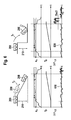
- Fig. 3 shows an airborne situation of the vehicle 200 characterized by a low accident severity.
- the transition from the elevated ground to the ground at the bottom is represented considerably smoother.
- the vehicle 200 is shown in an additional airborne position, represented in dashed lines, between its positions at the beginning and the end of the airborne situation.
- the airborne position of the vehicle 200 in dashed lines shows that, here, the distance of the vehicle 200 from the ground is substantially shorter than in Fig. 2 .
- the vehicle maintains a substantially parallel orientation relative to the ground both in the airborne phase and in the landing, as opposed to Fig. 2 .
- One aspect of the inventive approach consists in the fact that the airborne situation of the vehicle 200 is detected via the vertical acceleration, as it is apparent from Fig. 2 .
- a counter may be started, for example. From the counter reading exceeding one or more threshold values, conclusions regarding the severity of the subsequent impact may be drawn, as this may serve to estimate the airborne time directly or at least indirectly.
- the speed of the vehicle at the impact which provides an indication of the accident severity to be expected, may be determined from this airborne time.
- Fig. 4 shows, in an upper sub diagram, a vertical acceleration of a vehicle and, in a lower sub diagram, an exemplary characteristic curve of a counter according to an embodiment of the present invention, by means of coordinate systems, wherein the quantities stated are plotted against the time.
- a first coordinate system 410 of the upper sub diagram the time t is plotted on the abscissa.
- a vertical acceleration a z of the vehicle 200 along the z axis, which is oriented substantially at right angles to the vehicle 200.
- a signal waveform 411 describes a course of the vertical acceleration a z of the vehicle 200 throughout the duration of a free fall.
- Two lines 412 and 413 running in parallel to the abscissa limit a range of acceleration values around the value of the acceleration of gravity of 1 g, so that is these lines 412 and 413 e.g. denote a tolerance range of 0.8g to 1.2g around the value of the acceleration of gravity of 1 g, for example.
- Fig. 4 shows that an airborne situation of the vehicle 200 is detected at the exact point in time at which the signal waveform 411 exceeds the line 412.
- a second coordinate system 420 of the lower sub diagram of Fig. 4 again the time t is plotted on the abscissa. Values of a counter reading are plotted on the ordinate. At the level of a counter reading representing a threshold value Thd0 for an accident severity or safety relevant airborne situation of the vehicle to be expected, a line 421, which represents this acceleration threshold value Thd0, is illustrated in parallel to the abscissa.
- a graph 422 represents an airborne time T F as a function of the time t and the increments of the counter reading values. An intersection of the line 421 and the graph 422 identifies a point in time, at which a detecting of the accident severity or safety relevant airborne situation of vehicle 200 to be expected is effected.
- the two coordinate systems 410,420 of Fig. 4 are arranged on top of each other such that it is apparent that the gradient of the graph 422 in the coordinate system 420 begins with the signal waveform 411 exceeding the line 412 and ends with the signal waveform 411 falling below the line 412.
- the points of exceeding and falling below and/or of the beginning and the end of the gradient of the graph 422 are characterized by two dashed lines running in parallel to the ordinate.
- the falling of the acceleration signal 411 below the line 412 represents the impact of the vehicle 200 on the ground.
- a rotational speed of the wheels on the vehicle may also be used for a cost effective detection and/or plausibilization of an airborne situation of the vehicle.
- an airborne situation of the vehicle 200 may first be detected in the fact that a difference of the rotational speeds of the front axle and the rear axle of the vehicle 200 is small compared to a threshold.
- a rotational speed of a wheel of the front axle, ⁇ max,1 , and a rotational speed of a wheel of the rear axle, ⁇ max,2 do not exceed a given threshold Thd1.
- ⁇ max,1 may also represent the rotational speed of a wheel of the rear axle
- ⁇ max,2 may also represent the rotational speed of a wheel of the front axle. Defining ⁇ as the variable for the rotational speed, the following applies: ⁇ max , 1 ⁇ Thd ⁇ 1 ⁇ max , 2 ⁇ Thd ⁇ 1 ,
- Such a situation may also serve to detect a beginning of an airborne situation, as driven wheels will start to rotate very fast immediately on losing contact with the ground, and non-driven wheels will, in the airborne situation, have a speed slowly decreasing from the original speed present while the wheels were in contact with the ground, the reason for this being the missing "drive on ground”.
- the detection of the difference of the rotational speeds of the wheels of two different axles may serve to detect the airborne situation.
- Fig. 5 shows a flow chart of an embodiment of a method 500 for detecting an airborne situation of a vehicle according to an embodiment of the present invention, wherein rotational speeds of the wheels of the vehicle 200 are used for the detection of the airborne situation.
- a first rotational speed signal, ⁇ max,1 , ⁇ max,2 which represents a rotational speed of a wheel of a first axle
- a second rotational speed signal, ⁇ max,1 , ⁇ max,2 which represents a rotational speed of a wheel of a second axle
- a second step of comparing 520 the first rotational speed signal ⁇ max,1 , ⁇ max,2 and the second rotational speed signal ⁇ max,1 , ⁇ max,2 are compared to a predetermined rotational speed signal threshold value Thd1, in order to detect an airborne situation of the vehicle 200 when the first ⁇ max,1 , ⁇ max,2 and the second ⁇ max,1 , ⁇ max,2 rotational speed signals are larger than the predetermined rotational speed signal threshold value Thd1.
- a difference ⁇ 1,2 of the first ⁇ max,1 , ⁇ max,2 and second ⁇ max,1 , ⁇ max,2 rotational speed signals is formed, and the difference ⁇ 1,2 is compared to a predetermined difference threshold value Thd2, in order to detect an airborne situation of the vehicle 200 when the difference ⁇ 1,2 is larger than the predetermined difference threshold value Thd2.
- Fig. 6 shows a comparison of the airborne situation of a vehicle according to Fig. 3 , which is characterized by a low accident severity, and the airborne situation of a vehicle according to Fig. 2 , which is characterized by an increased accident severity. In each case, a plausibilization function for the verification of an increased accident severity is added.
- FIG. 6 in a first part of the comparison, the airborne situation characterized by a low accident severity of Fig. 3 is shown together with the coordinate systems of Fig. 4 , which are extended by the component of the rotational speed difference ⁇ 1,2 of the front axle and the rear axle, which was already described above.
- the coordinate systems are represented on top of each other in the illustration so that, in the common representation, the ordinate exhibits three sections for the representation of each one of the components of the vertical acceleration a z , the airborne time T F and the rotational speed difference ⁇ 1,2 , each section being associated to an individual abscissa, on which the time t is plotted.
- a difference signal 620 for the rotational speed difference ⁇ 1,2 which is measured over the time t, exceeds the threshold Thd2 for a certain period of time.
- Fig. 6 shows that, although an airborne situation is detected in both situations, only the situation illustrated on the right will enable the detection of a safety relevant airborne situation or result in an active intervention in the trigger behavior of the total algorithm.
- Fig. 7 shows a functional concept and flow chart of a functional implementation of the above physical approach to the detection and plausibilization of an airborne situation by means of an embodiment of the present invention in the form of a plausibilization method.
- a step 710 after receiving an acceleration value a z for the vertical acceleration, there is effected a check whether or not the received value of a z lies in the defined band (i.e. in the tolerance range) around 1g. If the value lies within the defined band, an airborne time encoder and/or counter is incremented in a further step 720.
- the result value of the incrementing is compared to the threshold value Thd0 for an accident severity or safety relevant airborne situation of the vehicle to be expected. If the comparison shows that the threshold value Thd0 is exceeded, then, in a subsequent step 740, a respective input of e.g. an AND gate for a decision for or against a triggering of one or multiple passenger protection devices is set to logic "1", wherein, for plausibilizing the detected comparison result, the AND gate may e.g. comprise at least one further input.
- steps 750 and 760 are effected (e.g. in parallel to the steps 710, 720, 730), wherein, in the step 750, four wheel speeds ⁇ of wheels of the vehicle are subjected to a variance calculation, and, in the step 760, a maximum rotational speed ⁇ max , 2 for one of the wheels of the rear axle of the vehicle and a maximum rotational speed ⁇ max,1 for one of the wheels of the front axle of the vehicle are compared to a threshold value Thd1 for a maximum rotational speed.
- step 740 is effected, in which a further respective input of the AND gate for the decision for or against a triggering of one or multiple passenger protection devices is set to logic "1".
- step 750 may in addition to the step 760 be followed by a step 770, which represents ascertaining a difference ⁇ 1,2 between the rotational speed of one wheel of the front axle and the rotational speed of one wheel of the rear axle.
- a result of this ascertaining of a difference ⁇ 1,2 is, in a subsequent step 780, subjected to a comparison to a threshold value Thd2 for a maximum rotational speed difference. If the comparison shows that the threshold value Thd2 is exceeded, again a jump back to step 740 is made, in which a further respective input of the AND gate for the decision for or against the triggering of one or multiple passenger protection devices is set to logic "1".
- the embodiment of the inventive method shown in Fig. 7 ends with a triggering of one or multiple passenger protection devices when all inputs of the AND gate are set to 1. Summing up, it may be stated that the steps 710, 720, 730 of Fig. 7 serve for the detection of an accident severity of an airborne situation, while the steps 750 and 760, and alternatively or additionally the steps 770 and 780, serve for the plausibilization of the detection of the accident severity. If at least one of the comparison steps 760, 780 has the result that the respective threshold value Thd1 and/or Thd2 is not exceeded, no triggering of a passenger protection device will be effected as not all of the inputs of the AND gate are set to logic "1 ".
Landscapes
- Engineering & Computer Science (AREA)
- Mechanical Engineering (AREA)
- Automotive Seat Belt Assembly (AREA)
Claims (8)
- Procédé (100) pour détecter qu'un véhicule (200) n'est plus en appui sur le sol, le procédé (100) comportant les étapes qui consistent à :recevoir (110) un signal d'accélération (411) qui représente une accélération essentiellement verticale du véhicule (200) etvérifier (120) si le signal d'accélération (411) dépasse une valeur prédéterminée (412) de seuil d'accélération et détecter que le véhicule (200) n'est plus en appui sur le sol lorsque le signal d'accélération (411) dépasse la valeur prédéterminée (412) de seuil d'accélération,le degré de gravité d'un accident attendu ou la sécurité de la situation de non appui sur le sol étant détectés par les étapes qui consistent à :lancer (720) un compteur lorsque le signal d'accélération (411) dépasse la valeur prédéterminée (412) de seuil d'accélération etcomparer (730) la mesure du compteur à une valeur prédéterminée (Thd0) de seuil de mesure du compteur pour détecter le degré de gravité attendu d'un accident du véhicule (200) ou la sécurité de la situation de non appui sur le sol du véhicule (200) lorsque la mesure du compteur est supérieure à la valeur prédéterminée (Thd0) de seuil de mesure du compteur.
- Procédé (100) selon la revendication 1, caractérisé en ce que dans l'étape de vérification (120), la valeur prédéterminée (412) de seuil d'accélération est située dans une plage de tolérance prédéterminée autour d'une valeur de l'accélération due à la gravité.
- Procédé (100) selon l'une des revendications 1 ou 2, caractérisé en ce que dans l'étape de comparaison (730), au moins une deuxième valeur prédéterminée de seuil de mesure du compteur est délivrée pour détecter au moins un deuxième degré de gravité d'un accident attendu du véhicule (200) ou la sécurité de la situation de non appui sur le sol du véhicule (200) lorsque la mesure du compteur est supérieure à la deuxième valeur prédéterminée de seuil de mesure de compteur, le deuxième degré représentant un accident de gravité plus élevée ou une plus grande sécurité de la situation de non appui sur le sol que le premier degré.
- Procédé de plausibilisation (700) en vue de plausibiliser la détection qu'un véhicule (200) n'est plus en appui sur le sol, caractérisé en ce que la situation de non appui sur le sol du véhicule (200) est détectée en exécutant les étapes du procédé (100) selon l'une quelconque des revendications 1 à 3, la détection d'une situation de non appui sur le sol étant plausibilisée en exécutant les étapes qui consistent à :recevoir (510) un premier signal (σmax,1, σmax,2) de vitesse de rotation représentant la vitesse de rotation d'une roue d'un premier essieu et recevoir (510) un deuxième signal (σmax,1, σmax,2) de vitesse de rotation représentant la vitesse de rotation d'une roue d'un deuxième essieu,comparer (520) le premier signal (σmax,1, σmax,2) de vitesse de rotation à une valeur prédéterminée (Thd1) de seuil de signal de vitesse de rotation et le deuxième signal (σmax,1, σmax,2) de vitesse de rotation à la valeur prédéterminée (Thd1) de seuil du signal de vitesse de rotation pour détecter que le véhicule (200) n'est plus en appui sur le sol lorsque le premier signal (σmax,1, σmax,2) de vitesse de rotation et le deuxième signal (σmax,1, σmax,2) de vitesse de rotation sont inférieurs à la valeur prédéterminée (Thd1) de seuil de signal de vitesse de rotation et/ouformer (530a) la différence (Δσ1,2) entre le premier signal (σmax,1, σmax,2) de vitesse de rotation et le deuxième signal (σmax,1, σmax,2) de vitesse de rotation et comparer (530b) la différence (Δσ1,2) à une valeur prédéterminée (Thd2) de seuil de différence pour détecter que le véhicule (200) n'est plus en appui que le sol lorsque la différence (Δσ1,2) est supérieure à la valeur prédéterminée (Thd2) de seuil de différence.
- Procédé selon l'une quelconque des revendications 1 à 4, caractérisé en ce qu'il est prévu en outre une étape de fourniture d'un signal de contrôle et en ce qu'au cours de cette étape de fourniture, le signal de contrôle est sélectionné sur la base de la détection d'une situation de non appui sur le sol, du degré détecté et/ou du deuxième degré détecté de gravité attendue de l'accident du véhicule (200) ou de la sécurité de la situation de non appui sur le sol du véhicule (200) pour contrôler au moins l'un des différents dispositifs de protection des occupants du véhicule (200).
- Procédé selon la revendication 5, caractérisé en ce que dans l'étape de fourniture, le signal de contrôle est sélectionné de telle sorte qu'il entraîne dans une unité de déclenchement la modification du seuil de déclenchement d'un des dispositifs de protection des occupants et/ou en ce que le signal de contrôle est sélectionné de telle sorte qu'il entraîne la plausibilisation d'une décision de déclenchement d'un dispositif de protection des occupants.
- Dispositif de contrôle présentant des unités configurées pour exécuter les étapes d'un procédé (100) selon l'une quelconque des revendications 1 à 6.
- Produit de programme informatique doté d'un code de programme conservé sur un support lisible par machine en vue d'exécuter les étapes du procédé (100) selon l'une quelconque des revendications 1 à 6 lorsque le programme est exécuté sur un dispositif de contrôle.
Priority Applications (1)
| Application Number | Priority Date | Filing Date | Title |
|---|---|---|---|
| EP09169029A EP2289753B1 (fr) | 2009-08-31 | 2009-08-31 | Procédé et dispositif de contrôle pour la détection et/ou la plausibilité d'une situation aéroportée d'un véhicule |
Applications Claiming Priority (1)
| Application Number | Priority Date | Filing Date | Title |
|---|---|---|---|
| EP09169029A EP2289753B1 (fr) | 2009-08-31 | 2009-08-31 | Procédé et dispositif de contrôle pour la détection et/ou la plausibilité d'une situation aéroportée d'un véhicule |
Publications (2)
| Publication Number | Publication Date |
|---|---|
| EP2289753A1 EP2289753A1 (fr) | 2011-03-02 |
| EP2289753B1 true EP2289753B1 (fr) | 2013-02-13 |
Family
ID=41321267
Family Applications (1)
| Application Number | Title | Priority Date | Filing Date |
|---|---|---|---|
| EP09169029A Active EP2289753B1 (fr) | 2009-08-31 | 2009-08-31 | Procédé et dispositif de contrôle pour la détection et/ou la plausibilité d'une situation aéroportée d'un véhicule |
Country Status (1)
| Country | Link |
|---|---|
| EP (1) | EP2289753B1 (fr) |
Cited By (5)
| Publication number | Priority date | Publication date | Assignee | Title |
|---|---|---|---|---|
| US12025632B2 (en) | 2021-09-30 | 2024-07-02 | Geotab Inc. | Low-power acceleration detection in a telematics device |
| US12375876B2 (en) | 2018-06-29 | 2025-07-29 | Geotab Inc. | Characterizing a vehicle collision |
| US12397785B1 (en) | 2024-02-09 | 2025-08-26 | Geotab Inc. | Systems and methods for detecting vehicle collisions |
| US12444306B2 (en) | 2021-02-03 | 2025-10-14 | Geotab Inc. | Methods for characterizing a vehicle collision |
| US12568348B2 (en) | 2024-03-18 | 2026-03-03 | Geotab Inc. | Systems, devices, and methods for communicating vehicle-related image data |
Families Citing this family (17)
| Publication number | Priority date | Publication date | Assignee | Title |
|---|---|---|---|---|
| EP2543552B1 (fr) * | 2011-07-04 | 2020-05-06 | Veoneer Sweden AB | Système de sécurité de véhicule |
| DE102011084842B4 (de) | 2011-10-20 | 2017-12-14 | Robert Bosch Gmbh | Verfahren zur Erzeugung einer Freiflughinweisinformation für ein Fahrzeug und Verfahren zur Erkennung eines Freiflugzustandes eines Fahrzeugs |
| DE102011084880B4 (de) | 2011-10-20 | 2016-12-15 | Robert Bosch Gmbh | Verfahren zur Erzeugung einer Freiflughinweisinformation für ein Fahrzeug und Verfahren zur Erkennung eines Freiflugzustandes eines Fahrzeugs |
| DE102011084877B3 (de) * | 2011-10-20 | 2012-12-27 | Robert Bosch Gmbh | Verfahren zur Erzeugung einer Freiflughinweisinformation für ein Fahrzeug und Verfahren zur Erkennung eines Freiflugzustandes eines Fahrzeugs |
| DE102012101273A1 (de) | 2012-02-17 | 2013-08-22 | Continental Automotive Gmbh | Verfahren zum Erkennen einer Flugphase des Fahrzeugs |
| DE102012101283A1 (de) | 2012-02-17 | 2013-08-22 | Continental Automotive Gmbh | Verfahren zum Erkennen einer Gefahrensituation aufgrund einer Flugphase des Fahrzeugs |
| DE102012101278A1 (de) | 2012-02-17 | 2013-08-22 | Continental Automotive Gmbh | Verfahren zur Steuerung eines Fahrzeugs während der Flugphase |
| DE102012101282A1 (de) | 2012-02-17 | 2013-08-22 | Continental Automotive Gmbh | Verfahren zum Erkennen einer drohenden Flugphase des Fahrzeugs mittels zumindest eines Umgebungserfassungssensors |
| DE102012101274A1 (de) | 2012-02-17 | 2013-08-22 | Continental Automotive Gmbh | Verfahren zur Steuerung eines Kraftfahrzeugs während und unmittelbar nach einer Flugphase |
| DE102012101279A1 (de) | 2012-02-17 | 2013-08-22 | Continental Automotive Gmbh | Verfahren zur Steuerung eines Fahrzeugs während der Flugphase |
| DE102012101277A1 (de) | 2012-02-17 | 2013-08-22 | Continental Automotive Gmbh | Verfahren zur Steuerung eines Fahrzeugs während einer Flugphase sowie daran anschließenden Landephase |
| DE102012101281A1 (de) | 2012-02-17 | 2013-08-22 | Continental Automotive Gmbh | Verfahren zur Steuerung der Lenkung eines Fahrzeugs |
| EP2657089A1 (fr) * | 2012-04-24 | 2013-10-30 | Autoliv Development AB | Système de sécurité de véhicule |
| DE102012104422A1 (de) | 2012-05-23 | 2013-11-28 | Continental Automotive Gmbh | Verfahren zum Erkennen einer Gefahrensituation aufgrund einer Flugphase des Fahrzeugs |
| DE102013221212A1 (de) * | 2013-10-18 | 2015-04-23 | Continental Teves Ag & Co. Ohg | Verfahren zum Erkennen eines Kontaktverlustes zwischen einem Fahrzeug und einer Straße |
| DE102017202534B4 (de) | 2017-02-16 | 2025-06-18 | Robert Bosch Gmbh | Verfahren zur Aktivierung von mindestens einer Sekundärfunktion eines Insassenschutzsystems eines Fahrzeugs |
| EP4274765A1 (fr) * | 2021-01-07 | 2023-11-15 | ZF Friedrichshafen AG | Procédé et appareil pour commander un dispositif de protection actionnable moyennant une détection de terrain accidenté et aérienne |
Family Cites Families (6)
| Publication number | Priority date | Publication date | Assignee | Title |
|---|---|---|---|---|
| DE19736328A1 (de) | 1997-08-21 | 1999-02-25 | Bayerische Motoren Werke Ag | Einrichtung und Verfahren zur Steuerung von Unfallschutz-Auslöseeinrichtungen in Kraftfahrzeugen |
| US6292759B1 (en) * | 1998-11-19 | 2001-09-18 | Delphi Technologies, Inc. | Vehicle attitude angle estimation using sensed signal blending |
| DE10232567A1 (de) | 2002-07-18 | 2004-02-05 | Cambiz Seyed-Asgari | Befestigbares Behältnis |
| DE10235567A1 (de) * | 2002-08-03 | 2004-02-19 | Robert Bosch Gmbh | Vorrichtung zur Erkennung eines Überrollvorgangs |
| JP4073856B2 (ja) * | 2003-10-08 | 2008-04-09 | 三菱電機株式会社 | 車両のロールオーバ判定装置 |
| WO2005082680A1 (fr) | 2004-03-01 | 2005-09-09 | Continental Teves Ag & Co.Ohg | Dispositif pour determiner une tendance au basculement |
-
2009
- 2009-08-31 EP EP09169029A patent/EP2289753B1/fr active Active
Cited By (6)
| Publication number | Priority date | Publication date | Assignee | Title |
|---|---|---|---|---|
| US12375876B2 (en) | 2018-06-29 | 2025-07-29 | Geotab Inc. | Characterizing a vehicle collision |
| US12444306B2 (en) | 2021-02-03 | 2025-10-14 | Geotab Inc. | Methods for characterizing a vehicle collision |
| US12025632B2 (en) | 2021-09-30 | 2024-07-02 | Geotab Inc. | Low-power acceleration detection in a telematics device |
| US12222363B2 (en) | 2021-09-30 | 2025-02-11 | Geotab Inc. | Device for low-power acceleration detection in a telematics device |
| US12397785B1 (en) | 2024-02-09 | 2025-08-26 | Geotab Inc. | Systems and methods for detecting vehicle collisions |
| US12568348B2 (en) | 2024-03-18 | 2026-03-03 | Geotab Inc. | Systems, devices, and methods for communicating vehicle-related image data |
Also Published As
| Publication number | Publication date |
|---|---|
| EP2289753A1 (fr) | 2011-03-02 |
Similar Documents
| Publication | Publication Date | Title |
|---|---|---|
| EP2289753B1 (fr) | Procédé et dispositif de contrôle pour la détection et/ou la plausibilité d'une situation aéroportée d'un véhicule | |
| EP1236620B1 (fr) | Système de détection de tonneau pour véhicule | |
| US7206680B2 (en) | Method for determining a decision for the triggering of restraint means in a vehicle | |
| EP1552989B1 (fr) | Dispositif de détection de retournement de véhicule et procédé pour anticiper un retournement de véhicule | |
| EP2261089B1 (fr) | Procédé de contrôle pour la reconnaissance de collision d'un véhicule | |
| EP2261087B1 (fr) | Procédé et dispositif de contrôle pour détecter l'emplacement d'impact d'un objet sur un véhicule | |
| US6796397B2 (en) | Method of activating a passenger safety application in a motor vehicle | |
| US20030182042A1 (en) | Vehicle rollover detection system | |
| US8244437B2 (en) | Method and system for restraint deployment using lateral kinetic energy | |
| US20130124035A1 (en) | Method and device for determining a type of an impact of an object on a vehicle | |
| EP1619083B1 (fr) | Méthode et système pour la détection du retournement d'un véhicule | |
| JP4448846B2 (ja) | 乗員拘束システムのためのトリガ決定の形成のための方法 | |
| US9308876B2 (en) | Methods for generating an item of information for indicating an airborne state for a vehicle and method for detecting an airborne state of a vehicle | |
| JP2006525917A (ja) | 車両の乗員保護システム | |
| US20130090814A1 (en) | Method and device for the determination of at least one triggering parameter of personal protection means of a vehicle | |
| US7664587B2 (en) | Device for recognizing a vehicle overturn | |
| CN102448778A (zh) | 汽车侧翻的识别方法 | |
| US20130332032A1 (en) | Method and control unit for activating a safety device for a vehicle in a rollover situation | |
| US8116949B2 (en) | Method and device for determining an initial float angle for skid detection in rollover sensing | |
| EP2289740B1 (fr) | Procédé et dispositif de contrôle pour la détection d'un embardement de fossé d'un véhicule | |
| EP2394864B1 (fr) | Procédé et dispositif de contrôle pour l'activation de supports de sécurité du passager dans un véhicule | |
| EP2261088B1 (fr) | Procédé et dispositif de contrôle pour la classification de collision d'un véhicule | |
| KR20180116867A (ko) | 자동차 에어백 제어 시스템 및 방법 | |
| JP2008528377A (ja) | セーフティシステム | |
| KR102869078B1 (ko) | 차량의 회전거동 제어 장치 및 그 방법 |
Legal Events
| Date | Code | Title | Description |
|---|---|---|---|
| PUAI | Public reference made under article 153(3) epc to a published international application that has entered the european phase |
Free format text: ORIGINAL CODE: 0009012 |
|
| AK | Designated contracting states |
Kind code of ref document: A1 Designated state(s): AT BE BG CH CY CZ DE DK EE ES FI FR GB GR HR HU IE IS IT LI LT LU LV MC MK MT NL NO PL PT RO SE SI SK SM TR |
|
| RAP1 | Party data changed (applicant data changed or rights of an application transferred) |
Owner name: VOLVO CAR CORPORATION Owner name: ROBERT BOSCH GMBH |
|
| 17P | Request for examination filed |
Effective date: 20110902 |
|
| GRAP | Despatch of communication of intention to grant a patent |
Free format text: ORIGINAL CODE: EPIDOSNIGR1 |
|
| GRAS | Grant fee paid |
Free format text: ORIGINAL CODE: EPIDOSNIGR3 |
|
| GRAA | (expected) grant |
Free format text: ORIGINAL CODE: 0009210 |
|
| AK | Designated contracting states |
Kind code of ref document: B1 Designated state(s): AT BE BG CH CY CZ DE DK EE ES FI FR GB GR HR HU IE IS IT LI LT LU LV MC MK MT NL NO PL PT RO SE SI SK SM TR |
|
| REG | Reference to a national code |
Ref country code: GB Ref legal event code: FG4D |
|
| REG | Reference to a national code |
Ref country code: AT Ref legal event code: REF Ref document number: 596298 Country of ref document: AT Kind code of ref document: T Effective date: 20130215 |
|
| REG | Reference to a national code |
Ref country code: IE Ref legal event code: FG4D |
|
| REG | Reference to a national code |
Ref country code: DE Ref legal event code: R096 Ref document number: 602009013210 Country of ref document: DE Effective date: 20130411 |
|
| REG | Reference to a national code |
Ref country code: SE Ref legal event code: TRGR |
|
| REG | Reference to a national code |
Ref country code: AT Ref legal event code: MK05 Ref document number: 596298 Country of ref document: AT Kind code of ref document: T Effective date: 20130213 |
|
| REG | Reference to a national code |
Ref country code: NL Ref legal event code: VDEP Effective date: 20130213 |
|
| REG | Reference to a national code |
Ref country code: LT Ref legal event code: MG4D |
|
| PG25 | Lapsed in a contracting state [announced via postgrant information from national office to epo] |
Ref country code: ES Free format text: LAPSE BECAUSE OF FAILURE TO SUBMIT A TRANSLATION OF THE DESCRIPTION OR TO PAY THE FEE WITHIN THE PRESCRIBED TIME-LIMIT Effective date: 20130524 Ref country code: AT Free format text: LAPSE BECAUSE OF FAILURE TO SUBMIT A TRANSLATION OF THE DESCRIPTION OR TO PAY THE FEE WITHIN THE PRESCRIBED TIME-LIMIT Effective date: 20130213 Ref country code: NO Free format text: LAPSE BECAUSE OF FAILURE TO SUBMIT A TRANSLATION OF THE DESCRIPTION OR TO PAY THE FEE WITHIN THE PRESCRIBED TIME-LIMIT Effective date: 20130513 Ref country code: IS Free format text: LAPSE BECAUSE OF FAILURE TO SUBMIT A TRANSLATION OF THE DESCRIPTION OR TO PAY THE FEE WITHIN THE PRESCRIBED TIME-LIMIT Effective date: 20130613 Ref country code: LT Free format text: LAPSE BECAUSE OF FAILURE TO SUBMIT A TRANSLATION OF THE DESCRIPTION OR TO PAY THE FEE WITHIN THE PRESCRIBED TIME-LIMIT Effective date: 20130213 Ref country code: BG Free format text: LAPSE BECAUSE OF FAILURE TO SUBMIT A TRANSLATION OF THE DESCRIPTION OR TO PAY THE FEE WITHIN THE PRESCRIBED TIME-LIMIT Effective date: 20130513 |
|
| PG25 | Lapsed in a contracting state [announced via postgrant information from national office to epo] |
Ref country code: PL Free format text: LAPSE BECAUSE OF FAILURE TO SUBMIT A TRANSLATION OF THE DESCRIPTION OR TO PAY THE FEE WITHIN THE PRESCRIBED TIME-LIMIT Effective date: 20130213 Ref country code: LV Free format text: LAPSE BECAUSE OF FAILURE TO SUBMIT A TRANSLATION OF THE DESCRIPTION OR TO PAY THE FEE WITHIN THE PRESCRIBED TIME-LIMIT Effective date: 20130213 Ref country code: PT Free format text: LAPSE BECAUSE OF FAILURE TO SUBMIT A TRANSLATION OF THE DESCRIPTION OR TO PAY THE FEE WITHIN THE PRESCRIBED TIME-LIMIT Effective date: 20130613 Ref country code: FI Free format text: LAPSE BECAUSE OF FAILURE TO SUBMIT A TRANSLATION OF THE DESCRIPTION OR TO PAY THE FEE WITHIN THE PRESCRIBED TIME-LIMIT Effective date: 20130213 Ref country code: GR Free format text: LAPSE BECAUSE OF FAILURE TO SUBMIT A TRANSLATION OF THE DESCRIPTION OR TO PAY THE FEE WITHIN THE PRESCRIBED TIME-LIMIT Effective date: 20130514 Ref country code: SI Free format text: LAPSE BECAUSE OF FAILURE TO SUBMIT A TRANSLATION OF THE DESCRIPTION OR TO PAY THE FEE WITHIN THE PRESCRIBED TIME-LIMIT Effective date: 20130213 Ref country code: BE Free format text: LAPSE BECAUSE OF FAILURE TO SUBMIT A TRANSLATION OF THE DESCRIPTION OR TO PAY THE FEE WITHIN THE PRESCRIBED TIME-LIMIT Effective date: 20130213 |
|
| PG25 | Lapsed in a contracting state [announced via postgrant information from national office to epo] |
Ref country code: HR Free format text: LAPSE BECAUSE OF FAILURE TO SUBMIT A TRANSLATION OF THE DESCRIPTION OR TO PAY THE FEE WITHIN THE PRESCRIBED TIME-LIMIT Effective date: 20130213 |
|
| PG25 | Lapsed in a contracting state [announced via postgrant information from national office to epo] |
Ref country code: SK Free format text: LAPSE BECAUSE OF FAILURE TO SUBMIT A TRANSLATION OF THE DESCRIPTION OR TO PAY THE FEE WITHIN THE PRESCRIBED TIME-LIMIT Effective date: 20130213 Ref country code: CZ Free format text: LAPSE BECAUSE OF FAILURE TO SUBMIT A TRANSLATION OF THE DESCRIPTION OR TO PAY THE FEE WITHIN THE PRESCRIBED TIME-LIMIT Effective date: 20130213 Ref country code: RO Free format text: LAPSE BECAUSE OF FAILURE TO SUBMIT A TRANSLATION OF THE DESCRIPTION OR TO PAY THE FEE WITHIN THE PRESCRIBED TIME-LIMIT Effective date: 20130213 Ref country code: DK Free format text: LAPSE BECAUSE OF FAILURE TO SUBMIT A TRANSLATION OF THE DESCRIPTION OR TO PAY THE FEE WITHIN THE PRESCRIBED TIME-LIMIT Effective date: 20130213 Ref country code: EE Free format text: LAPSE BECAUSE OF FAILURE TO SUBMIT A TRANSLATION OF THE DESCRIPTION OR TO PAY THE FEE WITHIN THE PRESCRIBED TIME-LIMIT Effective date: 20130213 Ref country code: NL Free format text: LAPSE BECAUSE OF FAILURE TO SUBMIT A TRANSLATION OF THE DESCRIPTION OR TO PAY THE FEE WITHIN THE PRESCRIBED TIME-LIMIT Effective date: 20130213 |
|
| PLBE | No opposition filed within time limit |
Free format text: ORIGINAL CODE: 0009261 |
|
| STAA | Information on the status of an ep patent application or granted ep patent |
Free format text: STATUS: NO OPPOSITION FILED WITHIN TIME LIMIT |
|
| PG25 | Lapsed in a contracting state [announced via postgrant information from national office to epo] |
Ref country code: IT Free format text: LAPSE BECAUSE OF FAILURE TO SUBMIT A TRANSLATION OF THE DESCRIPTION OR TO PAY THE FEE WITHIN THE PRESCRIBED TIME-LIMIT Effective date: 20130213 |
|
| 26N | No opposition filed |
Effective date: 20131114 |
|
| REG | Reference to a national code |
Ref country code: DE Ref legal event code: R097 Ref document number: 602009013210 Country of ref document: DE Effective date: 20131114 |
|
| REG | Reference to a national code |
Ref country code: CH Ref legal event code: PL |
|
| GBPC | Gb: european patent ceased through non-payment of renewal fee |
Effective date: 20130831 |
|
| PG25 | Lapsed in a contracting state [announced via postgrant information from national office to epo] |
Ref country code: LI Free format text: LAPSE BECAUSE OF NON-PAYMENT OF DUE FEES Effective date: 20130831 Ref country code: MC Free format text: LAPSE BECAUSE OF FAILURE TO SUBMIT A TRANSLATION OF THE DESCRIPTION OR TO PAY THE FEE WITHIN THE PRESCRIBED TIME-LIMIT Effective date: 20130213 Ref country code: CH Free format text: LAPSE BECAUSE OF NON-PAYMENT OF DUE FEES Effective date: 20130831 |
|
| REG | Reference to a national code |
Ref country code: IE Ref legal event code: MM4A |
|
| REG | Reference to a national code |
Ref country code: FR Ref legal event code: ST Effective date: 20140430 |
|
| PG25 | Lapsed in a contracting state [announced via postgrant information from national office to epo] |
Ref country code: IE Free format text: LAPSE BECAUSE OF NON-PAYMENT OF DUE FEES Effective date: 20130831 Ref country code: GB Free format text: LAPSE BECAUSE OF NON-PAYMENT OF DUE FEES Effective date: 20130831 |
|
| PG25 | Lapsed in a contracting state [announced via postgrant information from national office to epo] |
Ref country code: FR Free format text: LAPSE BECAUSE OF NON-PAYMENT OF DUE FEES Effective date: 20130902 |
|
| PG25 | Lapsed in a contracting state [announced via postgrant information from national office to epo] |
Ref country code: SM Free format text: LAPSE BECAUSE OF FAILURE TO SUBMIT A TRANSLATION OF THE DESCRIPTION OR TO PAY THE FEE WITHIN THE PRESCRIBED TIME-LIMIT Effective date: 20130213 |
|
| PG25 | Lapsed in a contracting state [announced via postgrant information from national office to epo] |
Ref country code: TR Free format text: LAPSE BECAUSE OF FAILURE TO SUBMIT A TRANSLATION OF THE DESCRIPTION OR TO PAY THE FEE WITHIN THE PRESCRIBED TIME-LIMIT Effective date: 20130213 Ref country code: CY Free format text: LAPSE BECAUSE OF FAILURE TO SUBMIT A TRANSLATION OF THE DESCRIPTION OR TO PAY THE FEE WITHIN THE PRESCRIBED TIME-LIMIT Effective date: 20130213 Ref country code: MT Free format text: LAPSE BECAUSE OF FAILURE TO SUBMIT A TRANSLATION OF THE DESCRIPTION OR TO PAY THE FEE WITHIN THE PRESCRIBED TIME-LIMIT Effective date: 20130213 |
|
| PG25 | Lapsed in a contracting state [announced via postgrant information from national office to epo] |
Ref country code: LU Free format text: LAPSE BECAUSE OF NON-PAYMENT OF DUE FEES Effective date: 20130831 Ref country code: HU Free format text: LAPSE BECAUSE OF FAILURE TO SUBMIT A TRANSLATION OF THE DESCRIPTION OR TO PAY THE FEE WITHIN THE PRESCRIBED TIME-LIMIT; INVALID AB INITIO Effective date: 20090831 Ref country code: MK Free format text: LAPSE BECAUSE OF FAILURE TO SUBMIT A TRANSLATION OF THE DESCRIPTION OR TO PAY THE FEE WITHIN THE PRESCRIBED TIME-LIMIT Effective date: 20130213 |
|
| PGFP | Annual fee paid to national office [announced via postgrant information from national office to epo] |
Ref country code: SE Payment date: 20250821 Year of fee payment: 17 |
|
| PGFP | Annual fee paid to national office [announced via postgrant information from national office to epo] |
Ref country code: DE Payment date: 20251021 Year of fee payment: 17 |