EP2289728B1 - Device for recovering brake energy - Google Patents
Device for recovering brake energy Download PDFInfo
- Publication number
- EP2289728B1 EP2289728B1 EP10172830.1A EP10172830A EP2289728B1 EP 2289728 B1 EP2289728 B1 EP 2289728B1 EP 10172830 A EP10172830 A EP 10172830A EP 2289728 B1 EP2289728 B1 EP 2289728B1
- Authority
- EP
- European Patent Office
- Prior art keywords
- energy
- flywheel
- converter device
- transmission
- gear mechanism
- Prior art date
- Legal status (The legal status is an assumption and is not a legal conclusion. Google has not performed a legal analysis and makes no representation as to the accuracy of the status listed.)
- Not-in-force
Links
- 230000008859 change Effects 0.000 claims description 14
- 238000006243 chemical reaction Methods 0.000 claims description 10
- 230000007246 mechanism Effects 0.000 claims 9
- 230000005540 biological transmission Effects 0.000 description 56
- 230000035939 shock Effects 0.000 description 12
- 238000011084 recovery Methods 0.000 description 7
- 238000000034 method Methods 0.000 description 6
- 230000008878 coupling Effects 0.000 description 5
- 238000010168 coupling process Methods 0.000 description 5
- 238000005859 coupling reaction Methods 0.000 description 5
- 230000002093 peripheral effect Effects 0.000 description 5
- 230000008569 process Effects 0.000 description 4
- 230000009467 reduction Effects 0.000 description 4
- 238000012546 transfer Methods 0.000 description 4
- 230000001133 acceleration Effects 0.000 description 3
- 230000001419 dependent effect Effects 0.000 description 3
- 238000013461 design Methods 0.000 description 3
- 238000004146 energy storage Methods 0.000 description 2
- 238000013519 translation Methods 0.000 description 2
- 230000009471 action Effects 0.000 description 1
- 230000003213 activating effect Effects 0.000 description 1
- 230000006978 adaptation Effects 0.000 description 1
- 230000003247 decreasing effect Effects 0.000 description 1
- 239000000446 fuel Substances 0.000 description 1
- 238000011835 investigation Methods 0.000 description 1
- 238000004519 manufacturing process Methods 0.000 description 1
- 238000005457 optimization Methods 0.000 description 1
- 230000001105 regulatory effect Effects 0.000 description 1
Images


Classifications
-
- B—PERFORMING OPERATIONS; TRANSPORTING
- B60—VEHICLES IN GENERAL
- B60K—ARRANGEMENT OR MOUNTING OF PROPULSION UNITS OR OF TRANSMISSIONS IN VEHICLES; ARRANGEMENT OR MOUNTING OF PLURAL DIVERSE PRIME-MOVERS IN VEHICLES; AUXILIARY DRIVES FOR VEHICLES; INSTRUMENTATION OR DASHBOARDS FOR VEHICLES; ARRANGEMENTS IN CONNECTION WITH COOLING, AIR INTAKE, GAS EXHAUST OR FUEL SUPPLY OF PROPULSION UNITS IN VEHICLES
- B60K6/00—Arrangement or mounting of plural diverse prime-movers for mutual or common propulsion, e.g. hybrid propulsion systems comprising electric motors and internal combustion engines ; Control systems therefor, i.e. systems controlling two or more prime movers, or controlling one of these prime movers and any of the transmission, drive or drive units Informative references: mechanical gearings with secondary electric drive F16H3/72; arrangements for handling mechanical energy structurally associated with the dynamo-electric machine H02K7/00; machines comprising structurally interrelated motor and generator parts H02K51/00; dynamo-electric machines not otherwise provided for in H02K see H02K99/00
- B60K6/08—Prime-movers comprising combustion engines and mechanical or fluid energy storing means
- B60K6/10—Prime-movers comprising combustion engines and mechanical or fluid energy storing means by means of a chargeable mechanical accumulator, e.g. flywheel
- B60K6/105—Prime-movers comprising combustion engines and mechanical or fluid energy storing means by means of a chargeable mechanical accumulator, e.g. flywheel the accumulator being a flywheel
-
- F—MECHANICAL ENGINEERING; LIGHTING; HEATING; WEAPONS; BLASTING
- F16—ENGINEERING ELEMENTS AND UNITS; GENERAL MEASURES FOR PRODUCING AND MAINTAINING EFFECTIVE FUNCTIONING OF MACHINES OR INSTALLATIONS; THERMAL INSULATION IN GENERAL
- F16D—COUPLINGS FOR TRANSMITTING ROTATION; CLUTCHES; BRAKES
- F16D5/00—Impulse couplings, i.e. couplings that alternately accelerate and decelerate the driven member
-
- F—MECHANICAL ENGINEERING; LIGHTING; HEATING; WEAPONS; BLASTING
- F16—ENGINEERING ELEMENTS AND UNITS; GENERAL MEASURES FOR PRODUCING AND MAINTAINING EFFECTIVE FUNCTIONING OF MACHINES OR INSTALLATIONS; THERMAL INSULATION IN GENERAL
- F16H—GEARING
- F16H33/00—Gearings based on repeated accumulation and delivery of energy
- F16H33/02—Rotary transmissions with mechanical accumulators, e.g. weights, springs, intermittently-connected flywheels
-
- B—PERFORMING OPERATIONS; TRANSPORTING
- B60—VEHICLES IN GENERAL
- B60W—CONJOINT CONTROL OF VEHICLE SUB-UNITS OF DIFFERENT TYPE OR DIFFERENT FUNCTION; CONTROL SYSTEMS SPECIALLY ADAPTED FOR HYBRID VEHICLES; ROAD VEHICLE DRIVE CONTROL SYSTEMS FOR PURPOSES NOT RELATED TO THE CONTROL OF A PARTICULAR SUB-UNIT
- B60W30/00—Purposes of road vehicle drive control systems not related to the control of a particular sub-unit, e.g. of systems using conjoint control of vehicle sub-units
- B60W30/18—Propelling the vehicle
- B60W30/18009—Propelling the vehicle related to particular drive situations
- B60W30/18109—Braking
- B60W30/18127—Regenerative braking
-
- Y—GENERAL TAGGING OF NEW TECHNOLOGICAL DEVELOPMENTS; GENERAL TAGGING OF CROSS-SECTIONAL TECHNOLOGIES SPANNING OVER SEVERAL SECTIONS OF THE IPC; TECHNICAL SUBJECTS COVERED BY FORMER USPC CROSS-REFERENCE ART COLLECTIONS [XRACs] AND DIGESTS
- Y02—TECHNOLOGIES OR APPLICATIONS FOR MITIGATION OR ADAPTATION AGAINST CLIMATE CHANGE
- Y02T—CLIMATE CHANGE MITIGATION TECHNOLOGIES RELATED TO TRANSPORTATION
- Y02T10/00—Road transport of goods or passengers
- Y02T10/60—Other road transportation technologies with climate change mitigation effect
- Y02T10/62—Hybrid vehicles
Definitions
- the invention relates to a device for recovering braking energy during deceleration of a moving inertial mass to convert the braking energy at least partially into mechanical energy and store, with a flywheel, which is connected via a gear with the inertial mass in operative connection.
- Such a device is for example in DE 30 11 833 A been described.
- braking energy can be at least partially converted into electrical energy and stored, which in turn can support an acceleration process during a subsequent startup of the motor vehicle.
- Suitable converter devices and electrical energy stores are already suitable in terms of their properties and cost-benefit efficiency for mass use in motor vehicles, but often associated with a considerable manufacturing effort.
- the known electrical systems for recovering braking energy in terms of maximum power consumption by the electrical components used, such as the generators, limited and can only convert the braking energy into usable energy within narrow limits.
- energy recovery from elevators or load lifting devices or other systems with frequently moving inertial masses there are usually similar limitations in practice that make efficient conversion and use of braking energy difficult.
- braking energy basically any kinetic energy is considered, which is usually converted into non-usable energy such as heat energy at a deceleration of an inertial mass, such as a vehicle.
- non-usable energy such as heat energy at a deceleration of an inertial mass, such as a vehicle.
- inertial mass such as a vehicle.
- frequent braking and restart must already take place, could already cause a recovery of a small proportion of otherwise unusable braking energy that the fuel consumption of motor vehicles could be lowered and their energy balance could be significantly improved.
- a difficulty in converting braking energy to mechanical energy, particularly rotational energy is that the conversion of braking energy is dependent on both the magnitude and difference of the kinetic energy involved or, in particular, the rotational speed of a wheel axle of the vehicle, as well as on the used mechanical energy storage such as the flywheel and its current speed is dependent.
- a device for recovering braking energy therefore requires a suitable gear, by means of which the braking energy converted into mechanical energy can be supplied in a suitable manner to the mechanical energy store.
- the known from practice converter devices and gears are either connected to a high design and costly effort or limited to a predetermined range of speeds or ranges of kinetic and mechanical energy.
- a device of the type mentioned has a gearbox with two planetary gears having non-rotatably interconnected sun gears and ring gears and a different circumference of the respective planet gears, and that the device is one between the inertial mass and the transmission arranged converter device for converting the braking energy into a torque sequence
- the transducer device comprises a non-rotationally symmetrical rotary body, which is engageable with a perpendicular to a rotational axis of the rotary body deflectable torque change body in operative connection
- the transducer device with the transmission in Active connection is and can change its rotational energy to at least partially transmit the change in the rotational energy of the transmission to the flywheel and cause a change in the stored rotational energy in the flywheel.
- a torque impulse is referred to as a torque momentarily acting on a rotating system such as, for example, the transmission or the flywheel.
- the duration of the torque shock is to be sufficiently low depending on the speeds and the rotational energies of the rotating systems, which acts on the torque shock to allow adjustment of the respective speed and an associated change in rotational energy before a subsequent torque shock on the rotating system or acting on the transmission.
- the chronological sequence of torque pulses acting in succession on the transmission can be predetermined such that a quasi-continuous torque is generated and causes an increase of the rotational energy stored in the flywheel via the transmission.
- the drive train of the transmission is connected to a planetary land of a planetary gear and the output train of the transmission with a planetary land of the other planetary gear.
- sun gears and ring gears same speeds of the sun gears and the ring gears of the two planetary gears are given.
- the sun gears and the ring gears are freely rotatably supported, so that the rotational speeds of the sun gears and ring gears depending on the rotational speeds of the drive and output line and in dependence on the torque acting on the transmission torque can set freely.
- a structurally simple embodiment of the transmission can be achieved in that the two planetary gear have a common ring gear.
- the two sun gears which have a respective adapted to the associated planetary gears, diverging perimeter, are connected to each other via a rigid central axis rotationally fixed.
- Each planetary gear has at least two, but preferably three or more planetary gears in an axially symmetrical arrangement.
- any rotational speed of the drive train is made possible in that the sun gears formed with a reduction rotate at an increased speed in the same direction with the drive train, while the interconnected ring gears rotate in the opposite direction.
- the speeds of the rotating systems can be significantly greater than the speed of the drive train. For design reasons, therefore, to avoid excessively high speeds an optimization of the translation or reduction ratios and the involved rotating systems and their adaptation to the usually to be transmitted energies are made.
- the caused by the sequence of torque surges change or increase the rotational energy of the transmission is transmitted to both the drive train and the drive train, so that a part of the transmitted to the transmission rotational energy is transferred back to the transducer device, but at least one further part of the rotational energy can be transferred to the flywheel and stored there.
- the interconnected sun gears and / or the interconnected ring gears of the two planetary gear are each rotatably connected to an additional mass.
- the additional masses can be used to make the energy transfer as efficient as possible.
- Large moments of inertia of the rotating elements allow a large energy transfer per torque shock, but extend the time required for a compensation of the impact and an adjustment of the short-term significantly changed speeds to the resulting speeds of the output and the drive shaft.
- Such a device is advantageously used and used for the recovery of braking energy in the braking of the loads.
- a constructively simple and based solely on mechanical principles of embodiment of the converter device can be achieved in that the converter device has a perpendicular to a drive train of the transmission arranged turntable with a non-rotationally symmetrical circumferential contour, which engages with a deflectable against a spring force cams can be brought.
- the turntable forms the non-rotationally symmetrical rotary body and the cam which can be deflected against a spring force forms the torque change body which can act on the turntable or the non-rotationally symmetrical rotary body.
- the peripheral contour of the turntable whose speed is initially proportional to a speed of the wheel axle of the vehicle and coincides with the speed of the drive train of the transmission is suitably designed so that the deflectable against a spring force cam during a complete revolution of the turntable at least once and preferably several times quasi-instantaneously deflected against the spring force and then relocated relatively slowly back to its original starting position.
- the duration of the torque shock may be affected by the circumferential contour of the turntable
- the amount of torque shock applied to the turntable via the cam depends substantially on the spring force acting on the cam.
- the spring force can be given or varied in an advantageous manner or changed regulated during operation.
- the transducer device has two rotationally interconnected rotary disks.
- the transducer device has two rotationally interconnected rotary disks.
- decoupling of the rotational speeds of the rotationally elastic interconnected hubs and thus the two areas of the drive train, which are associated with the converter device or the transmission can be achieved.
- Different speeds cause a relative rotation of the two rotors to each other, whereby mechanical energy can be stored in the example produced by a torsion spring torsionally elastic connection of the two hubs.
- the rotational speeds are due to the torsionally flexible coupling of the hubs again align, the stored in the torsionally flexible coupling mechanical energy is converted into rotational energy, in part is again transferred back to the transducer device, but is also partly transmitted to the gear connected to a turntable and causes a change in the rotational energy of the transmission.
- the device has a second converter device for converting the Has rotational energy of the flywheel in drive power for the vehicle, which is arranged between the transmission and the flywheel.
- the rotational energy stored in the flywheel can be transmitted via the second converter device to the transmission and thus also to the vehicle operatively connected to the drive train of the transmission and converted back into kinetic energy of the vehicle.
- By selectively activating the first or the second converter device can be specified whether kinetic energy of the vehicle to be converted into mechanical energy and stored in the flywheel or whether in the flywheel stored rotational energy via the second transducer device back to the vehicle and to be used for acceleration of the vehicle or for conversion into kinetic energy.
- both converter devices each have two rotationally interconnected rotary disks, an advantageous decoupling of the respective rotational speeds during the action of the successive torque pulses can be achieved by the two converter devices.
- the proportional shares of the desired conversion of kinetic energy or of braking energy into rotational energy of the flywheel or the opposite energy conversion are dependent inter alia on the moments of inertia of the rotating systems and the spring properties of the spring devices used. Another dependence is the transmission ratio of the power transmission paths of Geretes, as dictated for example by the respective circumference of the planetary gears and the sun gears.
- the respective parameters, which have an influence on the desired energy conversion and energy transfer, should expediently be coordinated with one another in a meaningful way.
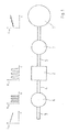
- a device for recovering braking energy which has a flywheel 1 as a mechanical energy storage.
- the flywheel 1 is connected via a gear 2 with a drive shaft 3 or with a wheel axle of a vehicle, not shown.
- a drive shaft 4 of the transmission 2 is connected to the drive shaft 3 of the vehicle, while an output shaft 5 of the transmission is connected to the flywheel 1.
- any suitable operative connection is considered, so that not necessarily a restriction to rigid connections and equal speeds of the drive shaft 4 of the transmission 2 and the drive shaft 3 of the vehicle and the output shaft 5 of the transmission 2 and the flywheel 1 must be assumed or specified ,
- a first converter device 6 is arranged between the drive shaft 3 of the vehicle and the transmission 2.
- a second converter device 7 is arranged between the gear 2 and the flywheel 1.
- a proportion of a decreasing kinetic energy E kin of the vehicle is converted into a series of torque pulses Mdt having substantially constant characteristics.
- the torque pulses Mdt act on the transmission 2 and cause a change in the rotational energy E red and a concomitant change in the rotational speeds of the rotating transmission elements. Since the transmission 2 is in operative connection both with the drive shaft 3 of the vehicle and with the flywheel 1, the rotational speeds of the rotating transmission elements will adapt or adjust as a function of the rotational speeds of the drive shaft 3 and the flywheel 1 and at least part of the the transmission 2 transmitted rotational energy E transmitted red via the transducer device 7 to the flywheel 1, the rotational energy E increases red and its speed increases accordingly.
- a first converter device 6 is shown.
- the second converter device 7 is usually configured identically.
- the transducer device 6 has a first hub 8 and a second hub 9, each having a non-rotationally symmetric peripheral contour 10.
- the two turntables 8, 9 are arranged at an angle relative to each other twisted. Between the two Turntables 8, 9 is an approximately circular arc-shaped curved torsion spring 11 is arranged, which causes a torsionally flexible coupling of the two turntables 8, 9.
- the circumferential contours 10 of the two turntables 8, 9 are scanned by a roller-shaped cam 12 bearing against both rotary disks 8, 9.
- the cam 12 is periodically against a spring force of a spring means 13, which is shown for illustrative purposes as a helical spring, depending on the simultaneously tapped circumferential contours 10 of the two turntables 8, 9 deflected.
- the cam 12 is sufficiently wide in order to simultaneously scan both turntables 8, 9, so that the deflection of the cam 12 is in each case predetermined by the radially further outward contour of the two turntables 8, 9.
- the leading first turntable 8 has the task to press the cam 12 against the spring force of the spring means 13 to the outside. This happens during a complete revolution of the turntable 8 three times. Shortly after the cam 12 is no longer abutting a projecting portion of the peripheral contour 10 of the first hub 8, but on the peripheral contour 10 of the second hub 9, the cam 12 due to a steep slope of the peripheral contour of the second hub caused by the spring force Apply rotational shock to the second hub 9, whereby a rotation of the second hub 9 is effected relative to the first hub 8. This will cause a rotation shock the transmission 2 exercised. In this way, the torsion spring 11 is rotated against its restoring force and stored mechanical energy in the torsionally elastic connection of the two turntables 8, 9.
- the torsion spring 11 causes an opposite acceleration of the second rotary disk 9 relative to the rotary disk 8 and an adjustment of the rotational speeds of the two rotary disks 8, 9 and a return of the second rotary disk 9 to a starting position relative to the first rotary disk 8.
- the torque pulses generated in this way are transmitted from the first converter device 6 to the transmission 2.
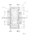
- the transmission 2, as it is in the Fig. 4-6 is shown as an example, has two interconnected planetary gear 14, 15.
- the two planetary gears 14, 15 have a common ring gear 16.
- the two sun gears 17, 18 of the planetary gear 14, 15 are rotatably connected to each other via a common center axis 19.
- the drive shaft 4 is connected via a planetary ridge 20 with the planetary gears 21 of the planetary gear 14, which is associated with the drive shaft 4.
- the output shaft 5 of the transmission 2 is connected via a planet web 22 with the planetary gears 23 of the planetary gear 15, which is associated with the output shaft 5.
- the planet gears 21 and the planet gears 23 and the respective associated sun gears 17 and 18 have a different circumference.
- the schematically indicated by the two arrows 24 and 25 power transmission paths in the transmission 2 thus have a different gear ratio. This leads to a substantial decoupling of the speeds of the vehicle in conjunction with the drive shaft 4 and the flywheel 1 in operative connection with the output shaft 5 of the transmission 2 and at the same time efficient transmission of the braking energy in rotational energy of the flywheel 1 and vice versa is possible.
Landscapes
- Engineering & Computer Science (AREA)
- General Engineering & Computer Science (AREA)
- Mechanical Engineering (AREA)
- Chemical & Material Sciences (AREA)
- Combustion & Propulsion (AREA)
- Transportation (AREA)
- Braking Arrangements (AREA)
- Arrangement Or Mounting Of Propulsion Units For Vehicles (AREA)
- Retarders (AREA)
- Transmission Devices (AREA)
Description
Die Erfindung betrifft eine Vorrichtung zur Rückgewinnung von Bremsenergie während des Abbremsens einer in Bewegung befindlichen trägen Masse, um die Bremsenergie mindestens teilweise in mechanische Energie umzuwandeln und zu speichern, mit einem Schwungrad, welches über ein Getriebe mit der trägen Masse in Wirkverbindung steht.The invention relates to a device for recovering braking energy during deceleration of a moving inertial mass to convert the braking energy at least partially into mechanical energy and store, with a flywheel, which is connected via a gear with the inertial mass in operative connection.
Eine derartige Vorrichtung ist beispielsweise in
Aus der Praxis sind verschiedene Verfahren und Vorrichtungen bekannt, die jeweils dazu verwendet werden können, während eines Bremsvorgangs beispielsweise eines Kraftfahrzeugs zumindest einen Anteil der üblicherweise in nichtnutzbare Energie umgewandelten kinetischen Energie in eine speicherbare und erneut nutzbringend verwendbar Energieform umzuwandeln. Bereits seit vielen Jahren wird versucht, Bremsenergie mindestens teilweise in Drehenergie eines auf dem Fahrzeug mitgeführten Schwungrads umzuwandeln und über einen längeren Zeitraum zu speichern, so dass beispielsweise ein anschließendes erneutes Anfahren des Fahrzeugs von dem Schwungrad unterstützt werden kann.Various methods and devices are known in practice which can each be used to convert at least a portion of the kinetic energy usually converted into unusable energy into a storable and again usefully usable form of energy during a braking process, for example of a motor vehicle. For many years attempts have been made to convert braking energy at least partially into rotational energy of a flywheel carried along on the vehicle and to store it over a relatively long period of time so that, for example, a subsequent restart of the vehicle can be assisted by the flywheel.
Obwohl bereits seit vielen Jahren erfolgversprechende Prototypen existieren und auch Erfahrungen aus praxisnahen Versuchen und umfangreichen Einsätzen beispielsweise im öffentlichen Nahverkehr gewonnen werden konnten, sind derzeit wohl aus Sicherheitsgründen und auf Grund einer als ungenügend empfundenen Effizienz der Energierückgewinnung keine serienreifen Vorrichtungen zur Umwandlung und Speicherung von Bremsenergie in mechanische Drehenergie bekannt.Although promising prototypes have existed for many years, and experience gained from practical trials and extensive missions, for example, in public transport, are currently probably due to security reasons and due to a perceived as insufficient efficiency of energy recovery no serial devices known for converting and storing braking energy into mechanical rotating energy.
Als eine erfolgversprechende Alternative werden derzeit bereits Verfahren und Vorrichtungen zum Einsatz gebracht, bei denen Bremsenergie mindestens teilweise in elektrische Energie umgewandelt und gespeichert werden kann, die ihrerseits einen Beschleunigungsvorgang während eines anschließenden Anfahrens des Kraftfahrzeugs unterstützen kann. Geeignete Wandler-Einrichtungen und elektrische Energiespeicher sind so hinsichtlich ihrer Eigenschaften und Kosten-Nutzen-Effizienz bereits geeignet für eine massenhafte Verwendung bei Kraftfahrzeugen, jedoch oftmals mit einem erheblichen Herstellungsaufwand verbunden. Zudem sind die bekannten elektrischen Systeme zur Rückgewinnung von Bremsenergie hinsichtlich der maximalen Leistungsaufnahme durch die verwendeten elektrischen Komponenten, beispielsweise die Generatoren, beschränkt und können nur innerhalb enger Grenzen die Bremsenergie in nutzbare Energie umwandeln. Auch bei der EnergieRückgewinnung bei Aufzügen oder Lasten-Hubvorrichtungen oder anderen Systemen mit häufig bewegten trägen Massen existieren in der Praxis üblicherweise vergleichbare Beschränkungen, welche eine effiziente Umwandlung und Nutzung der Bremsenergie erschweren.As a promising alternative, methods and devices are already being used in which braking energy can be at least partially converted into electrical energy and stored, which in turn can support an acceleration process during a subsequent startup of the motor vehicle. Suitable converter devices and electrical energy stores are already suitable in terms of their properties and cost-benefit efficiency for mass use in motor vehicles, but often associated with a considerable manufacturing effort. In addition, the known electrical systems for recovering braking energy in terms of maximum power consumption by the electrical components used, such as the generators, limited and can only convert the braking energy into usable energy within narrow limits. Similarly, in energy recovery from elevators or load lifting devices or other systems with frequently moving inertial masses, there are usually similar limitations in practice that make efficient conversion and use of braking energy difficult.
Als Bremsenergie wird dabei grundsätzlich jedwede kinetische Energie angesehen, die bei einer Abbremsung einer trägen Masse, beispielsweise eines Fahrzeugs, üblicherweise in nicht nutzbare Energie wie beispielsweise Wärmeenergie umgewandelt wird. Da insbesondere im innerstädtischen Verkehr ein häufiges Abbremsen und erneutes Anfahren erfolgen muss, könnte bereits eine Rückgewinnung eines kleinen Anteils der ansonsten nicht nutzbaren Bremsenergie bewirken, dass der Kraftstoffverbrauch von Kraftfahrzeugen gesenkt und deren Energiebilanz erheblich verbessert werden könnte.As braking energy basically any kinetic energy is considered, which is usually converted into non-usable energy such as heat energy at a deceleration of an inertial mass, such as a vehicle. Especially in the urban traffic frequent braking and restart must already take place, could already cause a recovery of a small proportion of otherwise unusable braking energy that the fuel consumption of motor vehicles could be lowered and their energy balance could be significantly improved.
Eine Schwierigkeit bei der Umwandlung von Bremsenergie in mechanische Energie, insbesondere in Drehenergie, bzw. Rotationsenergie, besteht darin, dass die Umwandlung der Bremsenergie sowohl von dem Betrag und der Differenz der dabei involvierten, bzw. umgesetzten kinetischen Energie und insbesondere von der Drehzahl einer Radachse des Fahrzeugs, als auch von dem verwendeten mechanischen Energiespeicher wie beispielsweise dem Schwungrad und dessen aktueller Drehzahl abhängig ist. Eine Vorrichtung zur Rückgewinnung von Bremsenergie benötigt demzufolge ein geeignetes Getriebe, mittels dessen die in mechanische Energie umgewandelte Bremsenergie in geeigneter Weise dem mechanischen Energiespeicher zugeführt werden kann. Die aus der Praxis bekannten Wandler-Einrichtungen und Getriebe sind entweder mit einem hohen konstruktiven und kostenintensiven Aufwand verbunden oder aber auf einen vorgegebenen Bereich von Drehzahlen bzw. Bereichen von kinetischer und mechanischer Energie beschränkt.One difficulty in converting braking energy to mechanical energy, particularly rotational energy, is that the conversion of braking energy is dependent on both the magnitude and difference of the kinetic energy involved or, in particular, the rotational speed of a wheel axle of the vehicle, as well as on the used mechanical energy storage such as the flywheel and its current speed is dependent. A device for recovering braking energy therefore requires a suitable gear, by means of which the braking energy converted into mechanical energy can be supplied in a suitable manner to the mechanical energy store. The known from practice converter devices and gears are either connected to a high design and costly effort or limited to a predetermined range of speeds or ranges of kinetic and mechanical energy.
Es wird deshalb als eine Aufgabe der vorliegenden Erfindung angesehen, eine Vorrichtung der eingangs genannten Gattung zur Rückgewinnung von Bremsenergie so auszugestalten, dass mit möglichst einfachen Mitteln Bremsenergie zuverlässig und effizient in Drehenergie eines Schwungrads umgewandelt bzw. übertragen werden kann, wobei die aktuelle Drehzahl des Schwungrads einen möglichst geringen Einfluss auf die Rückgewinnung der Bremsenergie haben soll.It is therefore regarded as an object of the present invention to design a device of the type mentioned for the recovery of braking energy so that with the simplest possible means braking energy can be reliably and efficiently converted into rotational energy of a flywheel or transmitted, the current speed the flywheel should have the least possible impact on the recovery of braking energy.
Diese Aufgabe wird erfindungsgemäß dadurch gelöst, dass eine Vorrichtung der eingangs genannten Gattung ein Getriebe mit zwei Planetengetrieben aufweist, die drehfest miteinander verbundene Sonnenräder und Hohlräder und einen voneinander abweichenden Umfang der jeweiligen Planetenräder aufweisen, und dass die Vorrichtung eine zwischen der trägen Masse und dem Getriebe angeordnete Wandler-Einrichtung zur Umwandlung der Bremsenergie in eine Drehmomentfolge aufweist, wobei die Wandler-Einrichtung einen nicht rotationssymmetrischen Drehkörper aufweist, der mit einem senkrecht zu einer Drehachse des Drehkörpers auslenkbaren Drehmomentänderungskörper in Wirkverbindung bringbar ist, und wobei die Wandler-Einrichtung mit dem Getriebe in Wirkverbindung steht und dessen Drehenergie verändern kann, um die Änderung der Drehenergie des Getriebes mindestens teilweise auf das Schwungrad zu übertragen und eine Änderung der in dem Schwungrad gespeicherten Drehenergie zu bewirken.This object is achieved in that a device of the type mentioned has a gearbox with two planetary gears having non-rotatably interconnected sun gears and ring gears and a different circumference of the respective planet gears, and that the device is one between the inertial mass and the transmission arranged converter device for converting the braking energy into a torque sequence, wherein the transducer device comprises a non-rotationally symmetrical rotary body, which is engageable with a perpendicular to a rotational axis of the rotary body deflectable torque change body in operative connection, and wherein the transducer device with the transmission in Active connection is and can change its rotational energy to at least partially transmit the change in the rotational energy of the transmission to the flywheel and cause a change in the stored rotational energy in the flywheel.
Während eines Bremsvorgangs wird die kinetische Energie des Fahrzeugs üblicherweise kontinuierlich reduziert. Untersuchungen haben ergeben, dass eine effiziente und zuverlässige Umwandlung und Übertragung der Bremsenergie auf ein Schwungrad dadurch ermöglicht bzw. begünstigt wird, dass die während eines Bremsvorgangs üblicherweise kontinuierlich in Wärmeenergie umgewandelte Bremsenergie zunächst in eine Folge von mehreren, in kurzen zeitlichen Abständen aufeinander folgenden Drehmomentstöße umgewandelt wird, die ihrerseits auf das mit dem Schwungrad in Wirkverbindung stehende Getriebe einwirken und über das Getriebe die in dem Schwungrad gespeicherte Drehenergie erhöhen können.During a braking process, the kinetic energy of the vehicle is usually continuously reduced. Investigations have shown that an efficient and reliable conversion and transmission of the braking energy to a flywheel is facilitated by the fact that the braking energy, which is usually converted continuously into thermal energy during a braking process, is first converted into a series of several torque impulses successive at short time intervals which, in turn, turns that on with the flywheel Actively acting gear acting and can increase the stored in the flywheel rotational energy through the transmission.
Als Drehmomentstoß wird dabei im Folgenden ein kurzzeitig auf ein rotierendes System wie beispielsweise das Getriebe oder das Schwungrad einwirkendes Drehmoment bezeichnet. Die Dauer des Drehmomentstoßes soll dabei in Abhängigkeit von den Drehzahlen und den Drehenergien der rotierenden Systeme, auf welche der Drehmomentstoß einwirkt, ausreichend gering sein, um eine Anpassung der jeweiligen Drehzahl und eine damit einhergehende Änderung der Drehenergie zu ermöglichen, bevor ein nachfolgender Drehmomentstoß auf das rotierende System bzw. auf das Getriebe einwirkt. Die zeitliche Abfolge von nacheinander auf das Getriebe einwirkenden Drehmomentstößen kann so vorgegeben werden, dass ein quasi-kontinuierliches Drehmoment erzeugt wird und über das Getriebe eine Erhöhung der in dem Schwungrad gespeicherten Drehenergie bewirkt. Es hat sich jedoch gezeigt, dass die Erzeugung einzelner Drehmomentstöße außerordentlich wichtig für die Energieübertragung ist und die Zeitdauer zwischen einzelnen Drehmomentstößen, bzw. die stoßfreie Zeit zwischen aufeinanderfolgenden Drehmomentstößen ausreichend groß sein sollte, um eine trägheitsbedingte Verzögerung der Stoßwirkung auf das Getriebe ausgleichen und die Drehzahlen der rotierenden Getriebeelemente wieder anpassen zu können, bevor der nächste Drehmomentstoß auf das Getriebe einwirkt,In the following, a torque impulse is referred to as a torque momentarily acting on a rotating system such as, for example, the transmission or the flywheel. The duration of the torque shock is to be sufficiently low depending on the speeds and the rotational energies of the rotating systems, which acts on the torque shock to allow adjustment of the respective speed and an associated change in rotational energy before a subsequent torque shock on the rotating system or acting on the transmission. The chronological sequence of torque pulses acting in succession on the transmission can be predetermined such that a quasi-continuous torque is generated and causes an increase of the rotational energy stored in the flywheel via the transmission. However, it has been found that the generation of individual torque surges is extremely important for energy transfer and the time between individual torque surges, or the bumpless time between successive torque surges should be sufficiently large to compensate for inertia delay of the impact on the transmission and the speeds to be able to readjust the rotating gear elements before the next torque shock acts on the gearbox,
Durch die Verwendung eines Drehkörpers, der mit einer drehmomentübertragenden Antriebs- oder Abtriebswelle des Getriebes oder mit der zugeordneten Welle des Schwungrads drehfest verbunden ist und mit einem Drehmomentänderungskörper in Wirkverbindungs gebracht werden kann, kann bei Bedarf in einfacher Weise und ausschließlich mechanisch eine Rotationsbewegung in eine Folge von Drehmomentstößen umgewandelt werden. Diese Drehmomentstöße können wiederum auf das Getriebe einwirken und dabei mit jedem Drehmomentstoß ein Drehmoment auf das Getriebe übertragen. Durch die Erzeugung diskreter Drehmomentstöße wird eine weitreichende und für die praktische Anwendung ausreichende Entkopplung der Drehzahlen des Getriebes und des Schwungrads ermöglicht und gleichzeitig eine effektive Übertragung eines Drehmoments als Summe vieler einzelner Drehmomentstöße gewährleistet.By using a rotary body, with a torque transmitting input or output shaft of the transmission or with the associated shaft of the flywheel rotatably connected and can be brought into operative connection with a torque-changing body, if necessary in a simple manner and only mechanically a rotational movement can be converted into a series of torque surges. These torque surges can in turn act on the transmission, transmitting torque to the transmission with each torque pulse. By generating discrete torque shocks a far-reaching and sufficient for practical application decoupling the speeds of the transmission and the flywheel and at the same time ensures effective transmission of torque as the sum of many individual torque shocks.
Der Antriebsstrang des Getriebes ist mit einem Planetensteg des einen Planetengetriebes und der Abtriebsstrang des Getriebes mit einem Planetensteg des anderen Planetengetriebes verbunden. Durch die drehfest miteinander verbundenen Sonnenräder und Hohlräder werden gleiche Drehzahlen der Sonnenräder bzw. der Hohlräder der beiden Planetengetriebe vorgegeben. Die Sonnenräder und die Hohlräder sind dabei frei drehbeweglich gelagert, so dass sich die Drehzahlen der Sonnenräder und Hohlräder in Abhängigkeit von den Drehzahlen des Antriebs- und Abtriebsstrangs sowie in Abhängigkeit von dem auf das Getriebe einwirkenden Drehmomentstößen frei einstellen können.The drive train of the transmission is connected to a planetary land of a planetary gear and the output train of the transmission with a planetary land of the other planetary gear. By rotatably interconnected sun gears and ring gears same speeds of the sun gears and the ring gears of the two planetary gears are given. The sun gears and the ring gears are freely rotatably supported, so that the rotational speeds of the sun gears and ring gears depending on the rotational speeds of the drive and output line and in dependence on the torque acting on the transmission torque can set freely.
Durch den unterschiedlichen Umfang der jeweiligen Planetenräder und damit einhergehend auch der jeweiligen Sonnenräder wird ein von 1 deutlich abweichendes Übersetzungsverhältnis vorgegeben, so dass eine Kraftübertragung durch das Getriebe auf zwei unterschiedlichen Wegen mit unterschiedlichem Übersetzungsverhältnis erfolgen kann, um eine Entkoppelung der an dem Abtriebsstrang und an dem Antriebsstrang des Getriebes vorherrschenden Drehzahlen zu ermöglichen. Mit Übersetzung wird dabei jede Änderung der Drehzahl bezeichnet, so dass auch eine tatsächlich bewirkte Verminderung der Drehzahl, bzw. eine Untersetzung denkbar ist.Due to the different circumference of the respective planet gears and, concomitantly, the respective sun gears, a gear ratio significantly different from 1 is specified, so that a Power transmission through the transmission can be done in two different ways with different gear ratio to allow decoupling of prevailing at the output line and the drive train of the transmission speeds. With translation, any change in the speed is referred to, so that an actually caused reduction in the speed, or a reduction is conceivable.
Eine konstruktiv einfache Ausgestaltung des Getriebes kann dadurch erreicht werden, dass die beiden Planetengetriebe ein gemeinsames Hohlrad aufweisen. Die beiden Sonnenräder, die einen jeweils an die zugeordneten Planetenräder angepassten, voneinander abweichenden Umfang aufweisen, sind über eine starre Mittelachse miteinander drehfest verbunden. Jedes Planetengetriebe weist mindestens zwei, vorzugsweise jedoch drei oder mehr Planetenräder in einer axialsymmetrischen Anordnung auf.A structurally simple embodiment of the transmission can be achieved in that the two planetary gear have a common ring gear. The two sun gears, which have a respective adapted to the associated planetary gears, diverging perimeter, are connected to each other via a rigid central axis rotationally fixed. Each planetary gear has at least two, but preferably three or more planetary gears in an axially symmetrical arrangement.
Bei einer Abbremsung des Abtriebsstrangs auf eine kleine Drehzahl wird eine beliebige Drehzahl des Antriebsstrangs dadurch ermöglicht, dass die mit einer Untersetzung ausgebildeten Sonnenräder mit vergrößerter Drehzahl in gleicher Richtung mit dem Antriebsstrang rotieren, während die miteinander verbundenen Hohlräder in entgegengesetzter Richtung rotieren. Die Drehzahlen der rotierenden Systeme können dabei deutlich größer als die Drehzahl des Antriebsstrangs sein. Aus konstruktiven Gründen sollte deshalb zur Vermeidung übermäßig großer Drehzahlen eine Optimierung der Übersetzungs- bzw. Untersetzungsverhältnisse und der beteiligten rotierenden Systeme und deren Anpassung an die üblicherweise zu übertragenden Energien vorgenommen werden.In a deceleration of the output train to a low speed any rotational speed of the drive train is made possible in that the sun gears formed with a reduction rotate at an increased speed in the same direction with the drive train, while the interconnected ring gears rotate in the opposite direction. The speeds of the rotating systems can be significantly greater than the speed of the drive train. For design reasons, therefore, to avoid excessively high speeds an optimization of the translation or reduction ratios and the involved rotating systems and their adaptation to the usually to be transmitted energies are made.
Die durch die Folge von Drehmomentstößen bewirkte Änderung bzw. Erhöhung der Drehenergie des Getriebes wird dabei sowohl auf den Abtriebsstrang als auch auf den Antriebsstrang übertragen, so dass ein Teil der auf das Getriebe übertragenen Drehenergie wieder auf die Wandler-Einrichtung zurückübertragen wird, jedoch zumindest ein weiterer Teil der Drehenergie auf das Schwungrad übertragen und dort gespeichert werden kann.The caused by the sequence of torque surges change or increase the rotational energy of the transmission is transmitted to both the drive train and the drive train, so that a part of the transmitted to the transmission rotational energy is transferred back to the transducer device, but at least one further part of the rotational energy can be transferred to the flywheel and stored there.
In besonders vorteilhafter Weise ist vorgesehen, dass die miteinander verbundenen Sonnenräder und/oder die miteinander verbundenen Hohlräder der beiden Planetengetriebe jeweils drehfest mit einer Zusatzmasse verbunden sind. Durch eine geeignete Vorgabe der Zusatzmasse oder der Zusatzmassen kann die Trägheit der rotierenden Elemente mit geringem Aufwand beeinflusst und an die jeweiligen Anforderungen angepasst werden.In a particularly advantageous manner, it is provided that the interconnected sun gears and / or the interconnected ring gears of the two planetary gear are each rotatably connected to an additional mass. By a suitable specification of the additional mass or additional masses, the inertia of the rotating elements can be influenced with little effort and adapted to the respective requirements.
Die Zusatzmassen können dazu verwendet werden, die Energieübertragung möglichst effizient zu gestalten. Große Trägheitsmomente der rotierenden Elemente ermöglichen einen großen Energieübertrag pro Drehmomentstoß, verlängern aber die Zeitdauer, die für einen Ausgleich der Stoßwirkung und eine Anpassung der kurzzeitig deutlich veränderten Drehzahlen an die resultierenden Drehzahlen der Abtriebs- und der Antriebswelle erforderlich ist.The additional masses can be used to make the energy transfer as efficient as possible. Large moments of inertia of the rotating elements allow a large energy transfer per torque shock, but extend the time required for a compensation of the impact and an adjustment of the short-term significantly changed speeds to the resulting speeds of the output and the drive shaft.
Nicht nur bei Fahrzeugen, sondern beispielsweise auch bei dem Betrieb eines Fahrstuhls oder eines Lastenkrans kann eine derartige Vorrichtung vorteilhaft verwendet und zur Zurückgewinnung von Bremsenergie bei dem Abbremsen der Lasten genutzt werden.Not only in vehicles, but also, for example, in the operation of an elevator or a crane can Such a device is advantageously used and used for the recovery of braking energy in the braking of the loads.
Eine konstruktiv einfache und ausschließlich auf mechanischen Wirkprinzipien beruhende Ausgestaltung der Wandler-Einrichtung kann dadurch erreicht werden, dass die Wandler-Einrichtung eine senkrecht zu einem Antriebsstrang des Getriebes angeordnete Drehscheibe mit einer nicht rotationssymmetrischen Umfangskontur aufweist, die mit einem gegen eine Federkraft auslenkbaren Nocken in Eingriff bringbar ist. Die Drehscheibe bildet den nicht rotationssymmetrischen Drehkörper und der gegen eine Federkraft auslenkbare Nocken bildet den Drehmomentänderungskörper, der auf die Drehscheibe, bzw. den nicht rotationssymmetrischen Drehkörper einwirken kann. Die Umfangskontur der Drehscheibe, deren Drehzahl zunächst proportional zu einer Drehzahl der Radachse des Fahrzeugs ist und mit der Drehzahl des Antriebsstrangs des Getriebes übereinstimmt, ist zweckmäßigerweise so ausgestaltet, dass der gegen eine Federkraft auslenkbare Nocken während einer vollständigen Umdrehung der Drehscheibe mindestens einmal und vorzugsweise mehrfach quasi-instantan gegen die Federkraft ausgelenkt und anschließend vergleichsweise langsam wieder in die ursprüngliche Ausgangsposition zurückverlagert wird.A constructively simple and based solely on mechanical principles of embodiment of the converter device can be achieved in that the converter device has a perpendicular to a drive train of the transmission arranged turntable with a non-rotationally symmetrical circumferential contour, which engages with a deflectable against a spring force cams can be brought. The turntable forms the non-rotationally symmetrical rotary body and the cam which can be deflected against a spring force forms the torque change body which can act on the turntable or the non-rotationally symmetrical rotary body. The peripheral contour of the turntable, whose speed is initially proportional to a speed of the wheel axle of the vehicle and coincides with the speed of the drive train of the transmission is suitably designed so that the deflectable against a spring force cam during a complete revolution of the turntable at least once and preferably several times quasi-instantaneously deflected against the spring force and then relocated relatively slowly back to its original starting position.
Während die Dauer des Drehmomentstoßes durch die Umfangskontur der Drehscheibe beeinflusst werden kann, hängt der Betrag des über den Nocken auf die Drehscheibe ausgeübten Drehmomentstoßes im Wesentlichen von der Federkraft ab, die auf den Nocken einwirkt. Die Federkraft kann in vorteilhafter Weise vorgegeben bzw. variiert oder während des Betriebs geregelt verändert werden.While the duration of the torque shock may be affected by the circumferential contour of the turntable, the amount of torque shock applied to the turntable via the cam depends substantially on the spring force acting on the cam. The spring force can be given or varied in an advantageous manner or changed regulated during operation.
Gemäß einer vorteilhaften Ausgestaltung des Erfindungsgedankens ist vorgesehen, dass die Wandler-Einrichtung zwei drehelastisch miteinander verbundene Drehscheiben aufweist. Auf diese Weise kann für die Dauer der von der Wandler-Einrichtung erzeugten Drehmomentstöße eine Entkopplung der Drehzahlen der drehelastisch miteinander verbundenen Drehscheiben und damit der beiden Bereiche des Antriebsstrangs, die der Wandler-Einrichtung bzw. dem Getriebe zugeordnet sind, erreicht werden. Unterschiedliche Drehzahlen bewirken eine relative Verdrehung der beiden Drehscheiben zueinander, wodurch mechanische Energie in der beispielsweise mittels einer Drehfeder erzeugten drehelastischen Verbindung der beiden Drehscheiben gespeichert werden kann. Im Rahmen einer im Anschluss an einen Drehmomentstoß und eine dadurch hervorgerufene kurzzeitige Änderung der Drehzahlen der beiden Drehscheiben werden sich die Drehzahlen auf Grund der drehelastischen Kopplung der Drehscheiben wieder angleichen, wobei die in der drehelastischen Kopplung gespeicherte mechanische Energie in Drehenergie umgewandelt wird, die zum Teil wieder auf die Wandler-Einrichtung zurückübertragen wird, jedoch zum Teil auch auf das mit einer Drehscheibe in Verbindung stehende Getriebe übertragen wird und eine Änderung der Drehenergie des Getriebes bewirkt.According to an advantageous embodiment of the inventive concept it is provided that the transducer device has two rotationally interconnected rotary disks. In this way, for the duration of the torque pulses generated by the converter device decoupling of the rotational speeds of the rotationally elastic interconnected hubs and thus the two areas of the drive train, which are associated with the converter device or the transmission can be achieved. Different speeds cause a relative rotation of the two rotors to each other, whereby mechanical energy can be stored in the example produced by a torsion spring torsionally elastic connection of the two hubs. As part of a subsequent torque shock and thereby caused a short-term change in the rotational speeds of the two hubs, the rotational speeds are due to the torsionally flexible coupling of the hubs again align, the stored in the torsionally flexible coupling mechanical energy is converted into rotational energy, in part is again transferred back to the transducer device, but is also partly transmitted to the gear connected to a turntable and causes a change in the rotational energy of the transmission.
Gemäß einer vorteilhaften Ausgestaltung des Erfindungsgedankens ist vorgesehen, dass die Vorrichtung eine zweite Wandler-Einrichtung zur Umwandlung der Drehenergie des Schwungrads in Antriebsenergie für das Fahrzeug aufweist, die zwischen dem Getriebe und dem Schwungrad angeordnet ist. Die in dem Schwungrad gespeicherte Drehenergie kann über die zweite Wandler-Einrichtung auf das Getriebe und damit auch auf das mit dem Abtriebsstrang des Getriebes in Wirkverbindung stehende Fahrzeug übertragen und in kinetische Energie des Fahrzeugs zurückgewandelt werden. Durch eine wahlweise Aktivierung der ersten oder der zweiten Wandler-Einrichtung kann vorgegeben werden, ob kinetische Energie des Fahrzeugs in mechanische Energie umgewandelt und in dem Schwungrad gespeichert werden soll oder ob in dem Schwungrad gespeicherte Drehenergie über die zweite Wandler-Einrichtung auf das Fahrzeug zurückübertragen und zur Beschleunigung des Fahrzeugs bzw. zur Umwandlung in kinetische Energie verwendet werden soll.According to an advantageous embodiment of the inventive concept it is provided that the device has a second converter device for converting the Has rotational energy of the flywheel in drive power for the vehicle, which is arranged between the transmission and the flywheel. The rotational energy stored in the flywheel can be transmitted via the second converter device to the transmission and thus also to the vehicle operatively connected to the drive train of the transmission and converted back into kinetic energy of the vehicle. By selectively activating the first or the second converter device can be specified whether kinetic energy of the vehicle to be converted into mechanical energy and stored in the flywheel or whether in the flywheel stored rotational energy via the second transducer device back to the vehicle and to be used for acceleration of the vehicle or for conversion into kinetic energy.
Sofern beide Wandler-Einrichtungen jeweils zwei drehelastisch miteinander verbundene Drehscheiben aufweisen, kann durch die beiden Wandler-Einrichtungen eine vorteilhafte Entkopplung der jeweiligen Drehzahlen während der Einwirkung der aufeinanderfolgenden Drehmomentstöße erreicht werden.If both converter devices each have two rotationally interconnected rotary disks, an advantageous decoupling of the respective rotational speeds during the action of the successive torque pulses can be achieved by the two converter devices.
Die betragsmäßigen Anteile der angestrebten Umwandlung von kinetischer Energie bzw. von Bremsenergie in Drehenergie des Schwungrads bzw. der entgegengesetzten Energieumwandlung sind unter anderem von den Trägheitsmomenten der rotierenden Systeme und den Federeigenschaften der verwendeten Federeinrichtungen abhängig. Eine weitere Abhängigkeit besteht in dem Übersetzungsverhältnis der Kraftübertragungswege des Getriebes, wie es beispielsweise durch den jeweiligen Umfang der Planetenräder und der Sonnenräder vorgegeben wird. Die jeweiligen Parameter, die einen Einfluss auf die angestrebte Energieumwandlung und Energieübertragung haben, sollten zweckmäßigerweise sinnvoll aufeinander abgestimmt sein.The proportional shares of the desired conversion of kinetic energy or of braking energy into rotational energy of the flywheel or the opposite energy conversion are dependent inter alia on the moments of inertia of the rotating systems and the spring properties of the spring devices used. Another dependence is the transmission ratio of the power transmission paths of Getriebes, as dictated for example by the respective circumference of the planetary gears and the sun gears. The respective parameters, which have an influence on the desired energy conversion and energy transfer, should expediently be coordinated with one another in a meaningful way.
Ausgehend von vereinfachenden Annahmen und Näherungen haben Untersuchungen ergeben, dass große Trägheitsmomente der rotierenden Systeme in Verbindung mit eine großen Federsteifigkeit der einzelnen Federeinrichtungen eine vergleichsweise steife Kopplung bewirken, wohingegen kleine Trägheitsmomente in Verbindung mit einer geringen Steifigkeit der verwendeten Federeinrichtungen eine vergleichsweise weiche Kopplung bewirken. Das minimal, bzw. maximal mögliche Übersetzungsverhältnis der verschiedenen Kraftübertragungswege des Getriebes, das nicht unterschritten werden sollte, wird durch die Reibungsverhältnisse zwischen den Zahnrädern der Planetenräder, Sonnenräder und Hohlräder sowie durch die jeweiligen Drehzahlen während des Betriebs maßgeblich bestimmt und vorgegeben.Based on simplifying assumptions and approximations, studies have shown that large moments of inertia of the rotating systems in conjunction with high spring stiffness of the individual spring devices cause a relatively stiff coupling, whereas small moments of inertia in conjunction with low stiffness of the spring devices used cause a relatively soft coupling. The minimum, or maximum possible transmission ratio of the various power transmission paths of the transmission, which should not be exceeded, is determined and specified by the friction ratios between the gears of the planetary gears, sun gears and ring gears and by the respective speeds during operation significantly.
Nachfolgend werden Ausführungsbeispiele des Erfindungsgedankens näher erläutert, die in der Zeichnung dargestellt sind. Es zeigt:
-
Fig. 1 eine schematische Darstellung einer erfindungsgemäßen Vorrichtung zur Rückgewinnung von Bremsenergie, -
Fig. 2 eine schematische Darstellung einer Seitenansicht einer Wandler-Einrichtung mit zwei drehelastisch miteinander verbundenen Drehscheiben, -
Fig. 3 eine Schnittansicht der inFig. 2 dargestellten Wandler-Einrichtung längs einer Linie III-III, -
Fig. 4 eine schematische Schnittansicht eines Getriebes mit zwei miteinander verbundenen Planetengetrieben, -
Fig. 5 eine Schnittansicht des inFig. 4 dargestellten Getriebes längs der Linie V-V und -
Fig. 6 eine Schnittansicht des inFig. 4 abgebildeten Getriebes längs einer Linie VI-VI.
-
Fig. 1 a schematic representation of a device according to the invention for the recovery of braking energy, -
Fig. 2 a schematic representation of a side view of a transducer device with two rotationally elastic interconnected hubs, -
Fig. 3 a sectional view of inFig. 2 illustrated transducer device along a line III-III, -
Fig. 4 a schematic sectional view of a transmission with two interconnected planetary gears, -
Fig. 5 a sectional view of the inFig. 4 shown gear along the line VV and -
Fig. 6 a sectional view of the inFig. 4 illustrated gear along a line VI-VI.
In
Zwischen der Antriebswelle 3 des Fahrzeugs und dem Getriebe 2 ist eine erste Wandler-Einrichtung 6 angeordnet. Zwischen dem Getriebe 2 und dem Schwungrad 1 ist eine zweite Wandler-Einrichtung 7 angeordnet.Between the
Durch die erste Wandler-Einrichtung 6 wird ein Anteil einer abnehmenden kinetischen Energie Ekin des Fahrzeugs in eine Folge von Drehmomentstößen Mdt mit im Wesentlichen gleichbleibenden Eigenschaften umgewandelt. Die Drehmomentstöße Mdt wirken auf das Getriebe 2 und bewirken eine Änderung der Drehenergie Erot und eine damit einhergehende Änderung der Drehzahlen der rotierenden Getriebeelemente. Da das Getriebe 2 sowohl mit der Antriebswelle 3 des Fahrzeugs als auch mit dem Schwungrad 1 in Wirkverbindung steht, werden sich die Drehzahlen der rotierenden Getriebeelemente in Abhängigkeit von den Drehzahlen der Antriebswelle 3 und des Schwungrads 1 anpassen bzw. angleichen und zumindest ein Teil der auf das Getriebe 2 übertragenen Drehenergie Erot über die Wandler-Einrichtung 7 auf das Schwungrad 1 übertragen, dessen Drehenergie Erot zunimmt und dessen Drehzahl sich entsprechend erhöht.By means of the
In
Wird die Wandler-Einrichtung 6 aktiviert, so werden die Umfangskonturen 10 der beiden Drehscheiben 8, 9 von einem walzenförmigen, an beiden Drehscheiben 8, 9 anliegenden Nocken 12 abgetastet. Der Nocken 12 wird dabei periodisch entgegen einer Federkraft einer Federeinrichtung 13, die zur Veranschaulichung als Schraubenfeder dargestellt ist, in Abhängigkeit von den gleichzeitig abgegriffenen Umfangskonturen 10 der beiden Drehscheiben 8, 9 ausgelenkt. Der Nocken 12 ist dabei ausreichend breit, um gleichzeitig beide Drehscheiben 8, 9 abzutasten, so dass die Auslenkung des Nockens 12 jeweils durch die radial weiter außenliegende Kontur der beiden Drehscheiben 8, 9 vorgegeben wird.If the
Bei dem lediglich exemplarisch dargestellten Ausführungsbeispiel hat die vorauseilende erste Drehscheibe 8 die Aufgabe, den Nocken 12 gegen die Federkraft der Federeinrichtung 13 nach außen zu drücken. Das geschieht während einer vollständigen Umdrehung der Drehscheibe 8 dreimal. Kurz nachdem der Nocken 12 nicht mehr an einem vorspringenden Bereich der Umfangskontur 10 der ersten Drehscheibe 8, sondern an der Umfangskontur 10 der zweiten Drehscheibe 9 anliegt, kann der Nocken 12 auf Grund einer steil abfallenden Flanke der Umfangskontur der zweiten Drehscheibe einen durch die Federkraft verursachten Drehstoß auf die zweite Drehscheibe 9 ausüben, wodurch eine Verdrehung der zweiten Drehscheibe 9 relativ zu der ersten Drehscheibe 8 bewirkt wird. Dadurch wird ein Drehstoß auf das Getriebe 2 ausgeübt. Auf diese Weise wird auch die Drehfeder 11 entgegen ihrer Rückstellkraft verdreht und mechanische Energie in der drehelastischen Verbindung der beiden Drehscheiben 8, 9 gespeichert. Anschließend bewirkt die Drehfeder 11 eine entgegengesetzte Beschleunigung der zweiten Drehscheibe 9 relativ zu der Drehscheibe 8 und eine Angleichung der Drehzahlen der beiden Drehscheiben 8, 9 bzw. eine Rückkehr der zweiten Drehscheibe 9 in eine Ausgangsposition relativ zu der ersten Drehscheibe 8.In the embodiment shown only as an example, the leading first turntable 8 has the task to press the
Die auf diese Weise erzeugten Drehmomentstöße werden von der ersten Wandler-Einrichtung 6 auf das Getriebe 2 übertragen. Das Getriebe 2, wie es in den
Durch zusätzliche Massen 26 und 27, die im Inneren des gemeinsamen Hohlrads 16 drehfest mit den Sonnenrädern 17, 18 sowie außerhalb des gemeinsamen Hohlrads 16 mit dieser drehfest verbunden sind, können in geeigneter Weise die Trägheitsmomente der rotierenden Elemente der Planetengetriebe 14 und 15 verändert und damit ebenso wie mit einer Vorgabe der Federkräfte letztendlich Einfluss auf die Energieumwandlung und Übertragung auf das Schwungrad 1 genommen werden.By
Claims (6)
- Apparatus for recovering braking energy during the braking of an inert mass which is in motion, in order to convert the braking energy at least partially into mechanical energy and to store it, having a flywheel which is operatively connected via a gear mechanism to the inert mass, characterized in that the gear mechanism (2) has two planetary gear mechanisms (14, 15) which have sun gears (17, 18) which are connected fixedly to one another so as to rotate together and internal gears (16) which are connected fixedly to one another so as to rotate together and a circumference of the respective planetary gears (21, 23) which differs from one another, and in that the apparatus has a converter device (6) which is arranged between the inert mass and the gear mechanism (2) for the conversion of braking energy into a torque sequence, the converter device (6) having a non-rotationally symmetrical rotary body which can be brought into an operative connection with a torque changing body which can be deflected perpendicularly with respect to a rotational axis of the rotary body, and the converter device (6) being operatively connected to the gear mechanism (2) and being capable of changing its rotational energy, in order to transmit the change in the rotational energy of the gear mechanism (2) at least partially to the flywheel (1) and to bring about a change in the rotational energy which is stored in the flywheel (1).
- Apparatus according to Claim 1, characterized in that the two planetary gear mechanisms (14, 15) have a common internal gear (16).
- Apparatus according to Claim 1 or 2, characterized in that the sun gears (17, 18) which are connected to one another and/or the internal gears (16) which are connected to one another are connected in each case fixedly to an additional mass so as to rotate with it.
- Apparatus according to one of the preceding claims, characterized in that the converter device (6) has a rotary disc (8) which is arranged perpendicularly with respect to a drive train (4) of the gear mechanism (2) and has a non-rotationally symmetrical circumferential contour (10) which can be brought into engagement with a cam (12) which can be deflected counter to a spring force.
- Apparatus according to Claim 3, characterized in that the converter device (6) has two rotary discs (8, 9) which are connected to one another in a rotationally elastic manner.
- Apparatus according to one of the preceding claims, characterized in that the apparatus has a second converter device (7) for the conversion of the rotational energy of the flywheel (1) into drive energy for the vehicle, which second converter device (7) is arranged between the gear mechanism (2) and the flywheel (1).
Applications Claiming Priority (1)
| Application Number | Priority Date | Filing Date | Title |
|---|---|---|---|
| DE102009026381A DE102009026381A1 (en) | 2009-08-14 | 2009-08-14 | Device for recovering braking energy |
Publications (3)
| Publication Number | Publication Date |
|---|---|
| EP2289728A2 EP2289728A2 (en) | 2011-03-02 |
| EP2289728A3 EP2289728A3 (en) | 2012-09-05 |
| EP2289728B1 true EP2289728B1 (en) | 2015-09-09 |
Family
ID=42988310
Family Applications (1)
| Application Number | Title | Priority Date | Filing Date |
|---|---|---|---|
| EP10172830.1A Not-in-force EP2289728B1 (en) | 2009-08-14 | 2010-08-13 | Device for recovering brake energy |
Country Status (2)
| Country | Link |
|---|---|
| EP (1) | EP2289728B1 (en) |
| DE (1) | DE102009026381A1 (en) |
Family Cites Families (8)
| Publication number | Priority date | Publication date | Assignee | Title |
|---|---|---|---|---|
| GB780200A (en) * | 1954-08-12 | 1957-07-31 | British Thomson Houston Co Ltd | Improvements in and relating to mechanical rotary motion coupling means |
| FR2461121A1 (en) * | 1979-04-13 | 1981-01-30 | Pompes Essa Mico | DEVICE FOR THE ACCUMULATION AND RETURN OF ENERGY COMPRISING A SPRING BLADE |
| DE3011833A1 (en) * | 1980-03-27 | 1981-10-08 | Tuttaß, Edmond, 4650 Gelsenkirchen-Horst | Automatic transmission with regenerative braking - has bob weights with adjustable radii for torque transfer |
| DE3224982C2 (en) * | 1982-07-03 | 1986-09-11 | Daimler-Benz Ag, 7000 Stuttgart | Drive arrangement for motor vehicles with a drive machine and a flywheel as energy storage |
| DE3602544A1 (en) * | 1986-01-29 | 1987-07-30 | Walter Schopf | Hybrid electric motor/gyro drive for motor vehicles |
| DD268031A1 (en) * | 1987-12-14 | 1989-05-17 | Schwermasch Nobas Veb | CIRCUIT ARRANGEMENT OF AN ENERGY-ECONOMIC HYDRAULIC DRIVE SYSTEM FOR CYCLICALLY WORKING MACHINES |
| US5052987A (en) * | 1989-04-14 | 1991-10-01 | Man Nutzfahrzeuge Ag | Stepless hydrostatic-mechanical transmission |
| DE9010321U1 (en) * | 1990-07-07 | 1991-11-07 | Schopf, Walter, 6370 Oberursel | Multiple continuously variable transmission combination for vehicle drive |
-
2009
- 2009-08-14 DE DE102009026381A patent/DE102009026381A1/en not_active Withdrawn
-
2010
- 2010-08-13 EP EP10172830.1A patent/EP2289728B1/en not_active Not-in-force
Also Published As
| Publication number | Publication date |
|---|---|
| DE102009026381A1 (en) | 2011-02-17 |
| EP2289728A3 (en) | 2012-09-05 |
| EP2289728A2 (en) | 2011-03-02 |
Similar Documents
| Publication | Publication Date | Title |
|---|---|---|
| DE112015002682T5 (en) | ELECTRIC BRAKE OPERATING DEVICE FOR VEHICLES | |
| DE102011009608A1 (en) | Electric damper | |
| DE3230121A1 (en) | Hybrid drive system for vehicles | |
| DE102010034281A1 (en) | Switching device for a transmission | |
| DE2610197A1 (en) | TORQUE CONVERTER | |
| WO2017202413A1 (en) | Hybrid drive module with an integrated transmission means in an axial arrangement | |
| DE102015208424A1 (en) | Coupling device for hybrid drives and method for operating a drive device of a motor vehicle | |
| DE102011084092A1 (en) | Electric machine i.e. prime mover, for transforming excess kinetic energy into electric energy in battery of motor car, has stator and rotor mounted independently to one another, where stator is connected or detached with housing | |
| DE102019214583A1 (en) | Bottom bracket drive | |
| DE102014221197B4 (en) | Clutch for a motor vehicle drive train with a two-stage planetary gear | |
| DE102018209451A1 (en) | planetary gear | |
| EP2558717A2 (en) | Wind energy installation azimuth or pitch drive | |
| DE102015121347B4 (en) | Radbremsrekuperationssystem | |
| DE102014223472A1 (en) | Swivel motor gearbox for a roll stabilization system | |
| EP2289728B1 (en) | Device for recovering brake energy | |
| DE102007005148A1 (en) | Angle superimposition gear unit for active guidance of vehicle, has input shaft connected with steering wheel of vehicle and output shaft connected with steering wheel of vehicle and gear | |
| EP3321116A1 (en) | Drive device for a motor vehicle and method for operating same | |
| DE102021114641A1 (en) | Drive unit and drive arrangement | |
| EP3892889A1 (en) | Wave gear drive | |
| DE102020210180A1 (en) | Drive train for a vehicle, in particular for an electric vehicle, or method for controlling a drive train of a vehicle | |
| DE102018127920A1 (en) | Wheel-selective vehicle steering | |
| WO2012175524A2 (en) | Device for the storage and conversion of energy | |
| EP3810447B1 (en) | Drive unit, drive assembly and hybrid motor vehicle | |
| EP3715624B1 (en) | Method for operating a wind turbine | |
| DE102012202308B4 (en) | Control unit for controlling a transmission, device with transmission and control unit, method for operating a transmission and computer program |
Legal Events
| Date | Code | Title | Description |
|---|---|---|---|
| PUAI | Public reference made under article 153(3) epc to a published international application that has entered the european phase |
Free format text: ORIGINAL CODE: 0009012 |
|
| AK | Designated contracting states |
Kind code of ref document: A2 Designated state(s): AL AT BE BG CH CY CZ DE DK EE ES FI FR GB GR HR HU IE IS IT LI LT LU LV MC MK MT NL NO PL PT RO SE SI SK SM TR |
|
| AX | Request for extension of the european patent |
Extension state: BA ME RS |
|
| PUAL | Search report despatched |
Free format text: ORIGINAL CODE: 0009013 |
|
| AK | Designated contracting states |
Kind code of ref document: A3 Designated state(s): AL AT BE BG CH CY CZ DE DK EE ES FI FR GB GR HR HU IE IS IT LI LT LU LV MC MK MT NL NO PL PT RO SE SI SK SM TR |
|
| AX | Request for extension of the european patent |
Extension state: BA ME RS |
|
| RIC1 | Information provided on ipc code assigned before grant |
Ipc: F16D 5/00 20060101ALI20120731BHEP Ipc: F16H 33/14 20060101ALI20120731BHEP Ipc: B60K 6/10 20060101AFI20120731BHEP |
|
| 17P | Request for examination filed |
Effective date: 20130220 |
|
| GRAP | Despatch of communication of intention to grant a patent |
Free format text: ORIGINAL CODE: EPIDOSNIGR1 |
|
| RIC1 | Information provided on ipc code assigned before grant |
Ipc: F16H 33/14 20060101ALI20150311BHEP Ipc: F16D 5/00 20060101ALI20150311BHEP Ipc: B60K 6/10 20060101AFI20150311BHEP |
|
| INTG | Intention to grant announced |
Effective date: 20150330 |
|
| GRAS | Grant fee paid |
Free format text: ORIGINAL CODE: EPIDOSNIGR3 |
|
| GRAA | (expected) grant |
Free format text: ORIGINAL CODE: 0009210 |
|
| AK | Designated contracting states |
Kind code of ref document: B1 Designated state(s): AL AT BE BG CH CY CZ DE DK EE ES FI FR GB GR HR HU IE IS IT LI LT LU LV MC MK MT NL NO PL PT RO SE SI SK SM TR |
|
| REG | Reference to a national code |
Ref country code: GB Ref legal event code: FG4D Free format text: NOT ENGLISH |
|
| REG | Reference to a national code |
Ref country code: AT Ref legal event code: REF Ref document number: 747823 Country of ref document: AT Kind code of ref document: T Effective date: 20150915 Ref country code: CH Ref legal event code: EP |
|
| REG | Reference to a national code |
Ref country code: IE Ref legal event code: FG4D Free format text: LANGUAGE OF EP DOCUMENT: GERMAN |
|
| REG | Reference to a national code |
Ref country code: DE Ref legal event code: R096 Ref document number: 502010010236 Country of ref document: DE |
|
| REG | Reference to a national code |
Ref country code: NL Ref legal event code: MP Effective date: 20150909 |
|
| PG25 | Lapsed in a contracting state [announced via postgrant information from national office to epo] |
Ref country code: LT Free format text: LAPSE BECAUSE OF FAILURE TO SUBMIT A TRANSLATION OF THE DESCRIPTION OR TO PAY THE FEE WITHIN THE PRESCRIBED TIME-LIMIT Effective date: 20150909 Ref country code: FI Free format text: LAPSE BECAUSE OF FAILURE TO SUBMIT A TRANSLATION OF THE DESCRIPTION OR TO PAY THE FEE WITHIN THE PRESCRIBED TIME-LIMIT Effective date: 20150909 Ref country code: LV Free format text: LAPSE BECAUSE OF FAILURE TO SUBMIT A TRANSLATION OF THE DESCRIPTION OR TO PAY THE FEE WITHIN THE PRESCRIBED TIME-LIMIT Effective date: 20150909 Ref country code: GR Free format text: LAPSE BECAUSE OF FAILURE TO SUBMIT A TRANSLATION OF THE DESCRIPTION OR TO PAY THE FEE WITHIN THE PRESCRIBED TIME-LIMIT Effective date: 20151210 Ref country code: NO Free format text: LAPSE BECAUSE OF FAILURE TO SUBMIT A TRANSLATION OF THE DESCRIPTION OR TO PAY THE FEE WITHIN THE PRESCRIBED TIME-LIMIT Effective date: 20151209 |
|
| REG | Reference to a national code |
Ref country code: LT Ref legal event code: MG4D |
|
| PG25 | Lapsed in a contracting state [announced via postgrant information from national office to epo] |
Ref country code: ES Free format text: LAPSE BECAUSE OF FAILURE TO SUBMIT A TRANSLATION OF THE DESCRIPTION OR TO PAY THE FEE WITHIN THE PRESCRIBED TIME-LIMIT Effective date: 20150909 Ref country code: SE Free format text: LAPSE BECAUSE OF FAILURE TO SUBMIT A TRANSLATION OF THE DESCRIPTION OR TO PAY THE FEE WITHIN THE PRESCRIBED TIME-LIMIT Effective date: 20150909 Ref country code: HR Free format text: LAPSE BECAUSE OF FAILURE TO SUBMIT A TRANSLATION OF THE DESCRIPTION OR TO PAY THE FEE WITHIN THE PRESCRIBED TIME-LIMIT Effective date: 20150909 |
|
| PG25 | Lapsed in a contracting state [announced via postgrant information from national office to epo] |
Ref country code: NL Free format text: LAPSE BECAUSE OF FAILURE TO SUBMIT A TRANSLATION OF THE DESCRIPTION OR TO PAY THE FEE WITHIN THE PRESCRIBED TIME-LIMIT Effective date: 20150909 |
|
| PG25 | Lapsed in a contracting state [announced via postgrant information from national office to epo] |
Ref country code: IT Free format text: LAPSE BECAUSE OF FAILURE TO SUBMIT A TRANSLATION OF THE DESCRIPTION OR TO PAY THE FEE WITHIN THE PRESCRIBED TIME-LIMIT Effective date: 20150909 Ref country code: EE Free format text: LAPSE BECAUSE OF FAILURE TO SUBMIT A TRANSLATION OF THE DESCRIPTION OR TO PAY THE FEE WITHIN THE PRESCRIBED TIME-LIMIT Effective date: 20150909 Ref country code: IS Free format text: LAPSE BECAUSE OF FAILURE TO SUBMIT A TRANSLATION OF THE DESCRIPTION OR TO PAY THE FEE WITHIN THE PRESCRIBED TIME-LIMIT Effective date: 20160109 Ref country code: CZ Free format text: LAPSE BECAUSE OF FAILURE TO SUBMIT A TRANSLATION OF THE DESCRIPTION OR TO PAY THE FEE WITHIN THE PRESCRIBED TIME-LIMIT Effective date: 20150909 Ref country code: SK Free format text: LAPSE BECAUSE OF FAILURE TO SUBMIT A TRANSLATION OF THE DESCRIPTION OR TO PAY THE FEE WITHIN THE PRESCRIBED TIME-LIMIT Effective date: 20150909 |
|
| PG25 | Lapsed in a contracting state [announced via postgrant information from national office to epo] |
Ref country code: PT Free format text: LAPSE BECAUSE OF FAILURE TO SUBMIT A TRANSLATION OF THE DESCRIPTION OR TO PAY THE FEE WITHIN THE PRESCRIBED TIME-LIMIT Effective date: 20160111 Ref country code: PL Free format text: LAPSE BECAUSE OF FAILURE TO SUBMIT A TRANSLATION OF THE DESCRIPTION OR TO PAY THE FEE WITHIN THE PRESCRIBED TIME-LIMIT Effective date: 20150909 Ref country code: RO Free format text: LAPSE BECAUSE OF FAILURE TO SUBMIT A TRANSLATION OF THE DESCRIPTION OR TO PAY THE FEE WITHIN THE PRESCRIBED TIME-LIMIT Effective date: 20150909 |
|
| REG | Reference to a national code |
Ref country code: DE Ref legal event code: R097 Ref document number: 502010010236 Country of ref document: DE |
|
| PLBE | No opposition filed within time limit |
Free format text: ORIGINAL CODE: 0009261 |
|
| STAA | Information on the status of an ep patent application or granted ep patent |
Free format text: STATUS: NO OPPOSITION FILED WITHIN TIME LIMIT |
|
| 26N | No opposition filed |
Effective date: 20160610 |
|
| REG | Reference to a national code |
Ref country code: FR Ref legal event code: PLFP Year of fee payment: 7 |
|
| PG25 | Lapsed in a contracting state [announced via postgrant information from national office to epo] |
Ref country code: DK Free format text: LAPSE BECAUSE OF FAILURE TO SUBMIT A TRANSLATION OF THE DESCRIPTION OR TO PAY THE FEE WITHIN THE PRESCRIBED TIME-LIMIT Effective date: 20150909 Ref country code: SI Free format text: LAPSE BECAUSE OF FAILURE TO SUBMIT A TRANSLATION OF THE DESCRIPTION OR TO PAY THE FEE WITHIN THE PRESCRIBED TIME-LIMIT Effective date: 20150909 |
|
| PG25 | Lapsed in a contracting state [announced via postgrant information from national office to epo] |
Ref country code: BE Free format text: LAPSE BECAUSE OF NON-PAYMENT OF DUE FEES Effective date: 20160831 |
|
| PG25 | Lapsed in a contracting state [announced via postgrant information from national office to epo] |
Ref country code: MC Free format text: LAPSE BECAUSE OF FAILURE TO SUBMIT A TRANSLATION OF THE DESCRIPTION OR TO PAY THE FEE WITHIN THE PRESCRIBED TIME-LIMIT Effective date: 20150909 |
|
| REG | Reference to a national code |
Ref country code: CH Ref legal event code: PL |
|
| PG25 | Lapsed in a contracting state [announced via postgrant information from national office to epo] |
Ref country code: LI Free format text: LAPSE BECAUSE OF NON-PAYMENT OF DUE FEES Effective date: 20160831 Ref country code: CH Free format text: LAPSE BECAUSE OF NON-PAYMENT OF DUE FEES Effective date: 20160831 |
|
| REG | Reference to a national code |
Ref country code: IE Ref legal event code: MM4A |
|
| PG25 | Lapsed in a contracting state [announced via postgrant information from national office to epo] |
Ref country code: IE Free format text: LAPSE BECAUSE OF NON-PAYMENT OF DUE FEES Effective date: 20160813 |
|
| REG | Reference to a national code |
Ref country code: FR Ref legal event code: PLFP Year of fee payment: 8 |
|
| PG25 | Lapsed in a contracting state [announced via postgrant information from national office to epo] |
Ref country code: LU Free format text: LAPSE BECAUSE OF NON-PAYMENT OF DUE FEES Effective date: 20160813 |
|
| REG | Reference to a national code |
Ref country code: AT Ref legal event code: MM01 Ref document number: 747823 Country of ref document: AT Kind code of ref document: T Effective date: 20160813 |
|
| PG25 | Lapsed in a contracting state [announced via postgrant information from national office to epo] |
Ref country code: AT Free format text: LAPSE BECAUSE OF NON-PAYMENT OF DUE FEES Effective date: 20160813 |
|
| PG25 | Lapsed in a contracting state [announced via postgrant information from national office to epo] |
Ref country code: SM Free format text: LAPSE BECAUSE OF FAILURE TO SUBMIT A TRANSLATION OF THE DESCRIPTION OR TO PAY THE FEE WITHIN THE PRESCRIBED TIME-LIMIT Effective date: 20150909 Ref country code: CY Free format text: LAPSE BECAUSE OF FAILURE TO SUBMIT A TRANSLATION OF THE DESCRIPTION OR TO PAY THE FEE WITHIN THE PRESCRIBED TIME-LIMIT Effective date: 20150909 Ref country code: HU Free format text: LAPSE BECAUSE OF FAILURE TO SUBMIT A TRANSLATION OF THE DESCRIPTION OR TO PAY THE FEE WITHIN THE PRESCRIBED TIME-LIMIT; INVALID AB INITIO Effective date: 20100813 |
|
| PG25 | Lapsed in a contracting state [announced via postgrant information from national office to epo] |
Ref country code: MT Free format text: LAPSE BECAUSE OF FAILURE TO SUBMIT A TRANSLATION OF THE DESCRIPTION OR TO PAY THE FEE WITHIN THE PRESCRIBED TIME-LIMIT Effective date: 20150909 Ref country code: TR Free format text: LAPSE BECAUSE OF FAILURE TO SUBMIT A TRANSLATION OF THE DESCRIPTION OR TO PAY THE FEE WITHIN THE PRESCRIBED TIME-LIMIT Effective date: 20150909 Ref country code: MK Free format text: LAPSE BECAUSE OF FAILURE TO SUBMIT A TRANSLATION OF THE DESCRIPTION OR TO PAY THE FEE WITHIN THE PRESCRIBED TIME-LIMIT Effective date: 20150909 |
|
| PG25 | Lapsed in a contracting state [announced via postgrant information from national office to epo] |
Ref country code: BG Free format text: LAPSE BECAUSE OF FAILURE TO SUBMIT A TRANSLATION OF THE DESCRIPTION OR TO PAY THE FEE WITHIN THE PRESCRIBED TIME-LIMIT Effective date: 20150909 |
|
| REG | Reference to a national code |
Ref country code: FR Ref legal event code: PLFP Year of fee payment: 9 |
|
| PG25 | Lapsed in a contracting state [announced via postgrant information from national office to epo] |
Ref country code: AL Free format text: LAPSE BECAUSE OF FAILURE TO SUBMIT A TRANSLATION OF THE DESCRIPTION OR TO PAY THE FEE WITHIN THE PRESCRIBED TIME-LIMIT Effective date: 20150909 |
|
| PGFP | Annual fee paid to national office [announced via postgrant information from national office to epo] |
Ref country code: FR Payment date: 20180824 Year of fee payment: 9 Ref country code: DE Payment date: 20180813 Year of fee payment: 9 |
|
| PGFP | Annual fee paid to national office [announced via postgrant information from national office to epo] |
Ref country code: GB Payment date: 20180828 Year of fee payment: 9 |
|
| REG | Reference to a national code |
Ref country code: DE Ref legal event code: R119 Ref document number: 502010010236 Country of ref document: DE |
|
| GBPC | Gb: european patent ceased through non-payment of renewal fee |
Effective date: 20190813 |
|
| PG25 | Lapsed in a contracting state [announced via postgrant information from national office to epo] |
Ref country code: DE Free format text: LAPSE BECAUSE OF NON-PAYMENT OF DUE FEES Effective date: 20200303 Ref country code: FR Free format text: LAPSE BECAUSE OF NON-PAYMENT OF DUE FEES Effective date: 20190831 |
|
| PG25 | Lapsed in a contracting state [announced via postgrant information from national office to epo] |
Ref country code: GB Free format text: LAPSE BECAUSE OF NON-PAYMENT OF DUE FEES Effective date: 20190813 |