EP2289659A1 - Vorrichtung zum Reibschweissverbinden von mindestens zwei Platten durch ein Verbindungselement mit einer Einrichtung zum Messen der ausgeübten Kraft und der Vorschublänge während des Verbindens - Google Patents
Vorrichtung zum Reibschweissverbinden von mindestens zwei Platten durch ein Verbindungselement mit einer Einrichtung zum Messen der ausgeübten Kraft und der Vorschublänge während des Verbindens Download PDFInfo
- Publication number
- EP2289659A1 EP2289659A1 EP10172958A EP10172958A EP2289659A1 EP 2289659 A1 EP2289659 A1 EP 2289659A1 EP 10172958 A EP10172958 A EP 10172958A EP 10172958 A EP10172958 A EP 10172958A EP 2289659 A1 EP2289659 A1 EP 2289659A1
- Authority
- EP
- European Patent Office
- Prior art keywords
- connecting element
- feed unit
- plate
- plates
- carrying plate
- Prior art date
- Legal status (The legal status is an assumption and is not a legal conclusion. Google has not performed a legal analysis and makes no representation as to the accuracy of the status listed.)
- Granted
Links
- 238000003466 welding Methods 0.000 claims abstract description 23
- 239000000463 material Substances 0.000 claims abstract description 15
- 229910052751 metal Inorganic materials 0.000 claims abstract description 11
- 239000002184 metal Substances 0.000 claims abstract description 11
- 229910000831 Steel Inorganic materials 0.000 claims abstract description 7
- 239000010959 steel Substances 0.000 claims abstract description 7
- 229910052782 aluminium Inorganic materials 0.000 claims abstract description 3
- XAGFODPZIPBFFR-UHFFFAOYSA-N aluminium Chemical compound [Al] XAGFODPZIPBFFR-UHFFFAOYSA-N 0.000 claims abstract description 3
- 230000035515 penetration Effects 0.000 claims abstract description 3
- 230000006835 compression Effects 0.000 claims description 2
- 238000007906 compression Methods 0.000 claims description 2
- 238000000034 method Methods 0.000 abstract description 13
- 238000013461 design Methods 0.000 description 7
- 239000010410 layer Substances 0.000 description 4
- 238000010438 heat treatment Methods 0.000 description 3
- 239000011241 protective layer Substances 0.000 description 3
- 239000000853 adhesive Substances 0.000 description 2
- 230000001070 adhesive effect Effects 0.000 description 2
- 238000000576 coating method Methods 0.000 description 2
- 238000004519 manufacturing process Methods 0.000 description 2
- 238000013459 approach Methods 0.000 description 1
- 238000004140 cleaning Methods 0.000 description 1
- 239000011248 coating agent Substances 0.000 description 1
- 238000004891 communication Methods 0.000 description 1
- 239000002131 composite material Substances 0.000 description 1
- 150000001875 compounds Chemical class 0.000 description 1
- 238000011109 contamination Methods 0.000 description 1
- 238000001816 cooling Methods 0.000 description 1
- 238000001514 detection method Methods 0.000 description 1
- 238000006073 displacement reaction Methods 0.000 description 1
- 239000012535 impurity Substances 0.000 description 1
- 238000005259 measurement Methods 0.000 description 1
- 239000000155 melt Substances 0.000 description 1
- 238000002844 melting Methods 0.000 description 1
- 230000008018 melting Effects 0.000 description 1
- 230000000149 penetrating effect Effects 0.000 description 1
- 230000002250 progressing effect Effects 0.000 description 1
- 230000000284 resting effect Effects 0.000 description 1
- 230000011664 signaling Effects 0.000 description 1
- 238000007711 solidification Methods 0.000 description 1
- 230000008023 solidification Effects 0.000 description 1
- 238000012360 testing method Methods 0.000 description 1
Images


Classifications
-
- B—PERFORMING OPERATIONS; TRANSPORTING
- B23—MACHINE TOOLS; METAL-WORKING NOT OTHERWISE PROVIDED FOR
- B23K—SOLDERING OR UNSOLDERING; WELDING; CLADDING OR PLATING BY SOLDERING OR WELDING; CUTTING BY APPLYING HEAT LOCALLY, e.g. FLAME CUTTING; WORKING BY LASER BEAM
- B23K20/00—Non-electric welding by applying impact or other pressure, with or without the application of heat, e.g. cladding or plating
- B23K20/12—Non-electric welding by applying impact or other pressure, with or without the application of heat, e.g. cladding or plating the heat being generated by friction; Friction welding
- B23K20/129—Non-electric welding by applying impact or other pressure, with or without the application of heat, e.g. cladding or plating the heat being generated by friction; Friction welding specially adapted for particular articles or workpieces
-
- B—PERFORMING OPERATIONS; TRANSPORTING
- B21—MECHANICAL METAL-WORKING WITHOUT ESSENTIALLY REMOVING MATERIAL; PUNCHING METAL
- B21J—FORGING; HAMMERING; PRESSING METAL; RIVETING; FORGE FURNACES
- B21J15/00—Riveting
- B21J15/02—Riveting procedures
- B21J15/027—Setting rivets by friction heating
-
- B—PERFORMING OPERATIONS; TRANSPORTING
- B23—MACHINE TOOLS; METAL-WORKING NOT OTHERWISE PROVIDED FOR
- B23K—SOLDERING OR UNSOLDERING; WELDING; CLADDING OR PLATING BY SOLDERING OR WELDING; CUTTING BY APPLYING HEAT LOCALLY, e.g. FLAME CUTTING; WORKING BY LASER BEAM
- B23K20/00—Non-electric welding by applying impact or other pressure, with or without the application of heat, e.g. cladding or plating
- B23K20/12—Non-electric welding by applying impact or other pressure, with or without the application of heat, e.g. cladding or plating the heat being generated by friction; Friction welding
- B23K20/121—Control circuits therefor
-
- B—PERFORMING OPERATIONS; TRANSPORTING
- B23—MACHINE TOOLS; METAL-WORKING NOT OTHERWISE PROVIDED FOR
- B23K—SOLDERING OR UNSOLDERING; WELDING; CLADDING OR PLATING BY SOLDERING OR WELDING; CUTTING BY APPLYING HEAT LOCALLY, e.g. FLAME CUTTING; WORKING BY LASER BEAM
- B23K20/00—Non-electric welding by applying impact or other pressure, with or without the application of heat, e.g. cladding or plating
- B23K20/12—Non-electric welding by applying impact or other pressure, with or without the application of heat, e.g. cladding or plating the heat being generated by friction; Friction welding
- B23K20/129—Non-electric welding by applying impact or other pressure, with or without the application of heat, e.g. cladding or plating the heat being generated by friction; Friction welding specially adapted for particular articles or workpieces
- B23K20/1295—Welding studs
-
- F—MECHANICAL ENGINEERING; LIGHTING; HEATING; WEAPONS; BLASTING
- F16—ENGINEERING ELEMENTS AND UNITS; GENERAL MEASURES FOR PRODUCING AND MAINTAINING EFFECTIVE FUNCTIONING OF MACHINES OR INSTALLATIONS; THERMAL INSULATION IN GENERAL
- F16B—DEVICES FOR FASTENING OR SECURING CONSTRUCTIONAL ELEMENTS OR MACHINE PARTS TOGETHER, e.g. NAILS, BOLTS, CIRCLIPS, CLAMPS, CLIPS OR WEDGES; JOINTS OR JOINTING
- F16B5/00—Joining sheets or plates, e.g. panels, to one another or to strips or bars parallel to them
- F16B5/08—Joining sheets or plates, e.g. panels, to one another or to strips or bars parallel to them by means of welds or the like
-
- B—PERFORMING OPERATIONS; TRANSPORTING
- B23—MACHINE TOOLS; METAL-WORKING NOT OTHERWISE PROVIDED FOR
- B23K—SOLDERING OR UNSOLDERING; WELDING; CLADDING OR PLATING BY SOLDERING OR WELDING; CUTTING BY APPLYING HEAT LOCALLY, e.g. FLAME CUTTING; WORKING BY LASER BEAM
- B23K2101/00—Articles made by soldering, welding or cutting
- B23K2101/18—Sheet panels
-
- B—PERFORMING OPERATIONS; TRANSPORTING
- B23—MACHINE TOOLS; METAL-WORKING NOT OTHERWISE PROVIDED FOR
- B23K—SOLDERING OR UNSOLDERING; WELDING; CLADDING OR PLATING BY SOLDERING OR WELDING; CUTTING BY APPLYING HEAT LOCALLY, e.g. FLAME CUTTING; WORKING BY LASER BEAM
- B23K2103/00—Materials to be soldered, welded or cut
- B23K2103/02—Iron or ferrous alloys
- B23K2103/04—Steel or steel alloys
-
- B—PERFORMING OPERATIONS; TRANSPORTING
- B23—MACHINE TOOLS; METAL-WORKING NOT OTHERWISE PROVIDED FOR
- B23K—SOLDERING OR UNSOLDERING; WELDING; CLADDING OR PLATING BY SOLDERING OR WELDING; CUTTING BY APPLYING HEAT LOCALLY, e.g. FLAME CUTTING; WORKING BY LASER BEAM
- B23K2103/00—Materials to be soldered, welded or cut
- B23K2103/08—Non-ferrous metals or alloys
- B23K2103/10—Aluminium or alloys thereof
-
- B—PERFORMING OPERATIONS; TRANSPORTING
- B23—MACHINE TOOLS; METAL-WORKING NOT OTHERWISE PROVIDED FOR
- B23K—SOLDERING OR UNSOLDERING; WELDING; CLADDING OR PLATING BY SOLDERING OR WELDING; CUTTING BY APPLYING HEAT LOCALLY, e.g. FLAME CUTTING; WORKING BY LASER BEAM
- B23K2103/00—Materials to be soldered, welded or cut
- B23K2103/18—Dissimilar materials
- B23K2103/20—Ferrous alloys and aluminium or alloys thereof
-
- B—PERFORMING OPERATIONS; TRANSPORTING
- B29—WORKING OF PLASTICS; WORKING OF SUBSTANCES IN A PLASTIC STATE IN GENERAL
- B29C—SHAPING OR JOINING OF PLASTICS; SHAPING OF MATERIAL IN A PLASTIC STATE, NOT OTHERWISE PROVIDED FOR; AFTER-TREATMENT OF THE SHAPED PRODUCTS, e.g. REPAIRING
- B29C65/00—Joining or sealing of preformed parts, e.g. welding of plastics materials; Apparatus therefor
- B29C65/02—Joining or sealing of preformed parts, e.g. welding of plastics materials; Apparatus therefor by heating, with or without pressure
- B29C65/06—Joining or sealing of preformed parts, e.g. welding of plastics materials; Apparatus therefor by heating, with or without pressure using friction, e.g. spin welding
- B29C65/0672—Spin welding
-
- B—PERFORMING OPERATIONS; TRANSPORTING
- B29—WORKING OF PLASTICS; WORKING OF SUBSTANCES IN A PLASTIC STATE IN GENERAL
- B29C—SHAPING OR JOINING OF PLASTICS; SHAPING OF MATERIAL IN A PLASTIC STATE, NOT OTHERWISE PROVIDED FOR; AFTER-TREATMENT OF THE SHAPED PRODUCTS, e.g. REPAIRING
- B29C65/00—Joining or sealing of preformed parts, e.g. welding of plastics materials; Apparatus therefor
- B29C65/56—Joining or sealing of preformed parts, e.g. welding of plastics materials; Apparatus therefor using mechanical means or mechanical connections, e.g. form-fits
- B29C65/60—Riveting or staking
- B29C65/601—Riveting or staking using extra riveting elements, i.e. the rivets being non-integral with the parts to be joined
- B29C65/603—Riveting or staking using extra riveting elements, i.e. the rivets being non-integral with the parts to be joined the rivets being pushed in blind holes
-
- B—PERFORMING OPERATIONS; TRANSPORTING
- B29—WORKING OF PLASTICS; WORKING OF SUBSTANCES IN A PLASTIC STATE IN GENERAL
- B29C—SHAPING OR JOINING OF PLASTICS; SHAPING OF MATERIAL IN A PLASTIC STATE, NOT OTHERWISE PROVIDED FOR; AFTER-TREATMENT OF THE SHAPED PRODUCTS, e.g. REPAIRING
- B29C66/00—General aspects of processes or apparatus for joining preformed parts
- B29C66/40—General aspects of joining substantially flat articles, e.g. plates, sheets or web-like materials; Making flat seams in tubular or hollow articles; Joining single elements to substantially flat surfaces
- B29C66/41—Joining substantially flat articles ; Making flat seams in tubular or hollow articles
-
- B—PERFORMING OPERATIONS; TRANSPORTING
- B29—WORKING OF PLASTICS; WORKING OF SUBSTANCES IN A PLASTIC STATE IN GENERAL
- B29C—SHAPING OR JOINING OF PLASTICS; SHAPING OF MATERIAL IN A PLASTIC STATE, NOT OTHERWISE PROVIDED FOR; AFTER-TREATMENT OF THE SHAPED PRODUCTS, e.g. REPAIRING
- B29C66/00—General aspects of processes or apparatus for joining preformed parts
- B29C66/80—General aspects of machine operations or constructions and parts thereof
- B29C66/83—General aspects of machine operations or constructions and parts thereof characterised by the movement of the joining or pressing tools
- B29C66/832—Reciprocating joining or pressing tools
- B29C66/8322—Joining or pressing tools reciprocating along one axis
-
- B—PERFORMING OPERATIONS; TRANSPORTING
- B29—WORKING OF PLASTICS; WORKING OF SUBSTANCES IN A PLASTIC STATE IN GENERAL
- B29C—SHAPING OR JOINING OF PLASTICS; SHAPING OF MATERIAL IN A PLASTIC STATE, NOT OTHERWISE PROVIDED FOR; AFTER-TREATMENT OF THE SHAPED PRODUCTS, e.g. REPAIRING
- B29C66/00—General aspects of processes or apparatus for joining preformed parts
- B29C66/80—General aspects of machine operations or constructions and parts thereof
- B29C66/84—Specific machine types or machines suitable for specific applications
- B29C66/845—C-clamp type or sewing machine type
-
- F—MECHANICAL ENGINEERING; LIGHTING; HEATING; WEAPONS; BLASTING
- F16—ENGINEERING ELEMENTS AND UNITS; GENERAL MEASURES FOR PRODUCING AND MAINTAINING EFFECTIVE FUNCTIONING OF MACHINES OR INSTALLATIONS; THERMAL INSULATION IN GENERAL
- F16B—DEVICES FOR FASTENING OR SECURING CONSTRUCTIONAL ELEMENTS OR MACHINE PARTS TOGETHER, e.g. NAILS, BOLTS, CIRCLIPS, CLAMPS, CLIPS OR WEDGES; JOINTS OR JOINTING
- F16B37/00—Nuts or like thread-engaging members
- F16B37/04—Devices for fastening nuts to surfaces, e.g. sheets, plates
- F16B37/06—Devices for fastening nuts to surfaces, e.g. sheets, plates by means of welding or riveting
- F16B37/061—Devices for fastening nuts to surfaces, e.g. sheets, plates by means of welding or riveting by means of welding
Definitions
- the invention relates to a device for connecting at least two plates, of which a supporting plate has a higher strength than a supported plate lying thereon, by means of a rotatably driven by a rotary feed connection element, with a collar the supported plate to the supporting plate and makes a friction welded connection to the supporting plate with a shaft.
- a device for the production of a friction-welded connection between a bolt and a plate has already been in accordance with the DE 10 2004 034 498 A1 a device is used, by means of which a pin rotated by a rotary feed unit is pressed onto a plate at a speed and pressure such that the friction heating between the pin and the plate causes the pin to melt in the area of contact with the plate and also occurs at this point melting of the plate surface occurs, whereby the process of friction welding is initiated, which signals by a sudden reduction in friction between the bolt and plate and thereby given torque drop that while maintaining the pressure of the bolt on the plate and cooling the Friction point of the friction welding process is done.
- the device is provided for this purpose with a displacement sensor, a torque sensor and a pressure force sensor to feed with these data control, which then controls the rotation feed device due to the detection of these measurement data and brings to a standstill to allow the resulting melt, the solidification and thus finally produce the friction-welded joint.
- Reibsch waittell is in the DE 196 20 814 A1 described and illustrated.
- Reibsch donetell is a three-body composite, consisting of a flat metal part and a metallic pad, which are connected to each other via a connecting body, that the connecting body below Rotation is pressed onto the flat metal part, this brings in the region of the connecting body to melt and penetrates to the metallic surface, with which the connecting body then connects by friction welding.
- About a collar or collar of the connecting body presses this on the flat metal part, wherein its shaft, which has penetrated the sheet metal part, is connected to the metallic pad by friction welding, whereby the MehrConsequentlyverbund is firmly held together via the connecting body.
- the invention has for its object to provide a device for connecting at least two plates via a connecting element, with which either the respective operating parameters, in particular speed, feed travel and feed pressure can be adjusted, in which case consideration must also be given to different materials since Both metal plates and plastic plates can be firmly connected to one another via a friction welding process.
- the supporting plate In the case of connecting two plates, the supporting plate must have a higher strength than a supported plate lying thereon.
- the rotary feed unit is provided with a measuring device which measures both an axial force exerted by the rotary feed unit and a respective feed length and the placement of the shank of the connecting element on the supported plate the pressure increase occurring thereby signaling the rotational advancing unit whose feed is adjustable to at least three successive stages of connection progressing, the first stage being set to penetrate the supported plate, the second stage to the friction welding of the stem to the supporting plate and the third stage ends the friction welding operation by increasing the axial force of the connecting element on the supporting plate.
- the process of the compound is inventively divided into three stages, which are traversed by a starting position of the rotary feed, in each of which a different treatment of the material of the plates via the connecting element.
- the initial position is that the rotational feed is first brought to an initial position in that upon placement of the connecting element on the supported plate at the rotational feed pressure increase is formed, which forms the initial signal for the following three stages of the feed of the connecting element.
- the length of the first stage is set to correspond to the length of penetration of the supported plate, followed by friction welding of the shaft to the supporting plate in the following second stage, followed by friction welding in the third stage under pressure of the rotary feed unit is terminated, that the connecting element is compressed on the supporting plate.
- the rotary feed unit so as to control the connecting element with respect the first stage changed speed and changed axial force rotates, so that in this intermediate stage the Surface of the supporting plate is effectively cleaned, whereby the friction welding in the second stage is prepared accordingly.
- the changes depend on the strength of the coatings of the supporting plate.
- the device is particularly suitable for frictionally welding a supporting steel plate to a light metal plate supported by it.
- the light metal supported plate is penetrated by the connecting member which softens the supported plate in its area, to thereafter fuse the surface of the supporting plate to prepare the friction welding between the connecting member and the supporting plate.
- the connecting element also made of steel. But it is also possible to manufacture both the plates and the connecting element made of plastic.
- the connecting element is actuated by the rotary feed unit in the first stage such that an advance of the connecting element in the first stage over the thickness of the supported plate, wherein a speed is set at which due to frictional heating caused the material of the supported plate in the Connecting element flows.
- the rotary feed device then rotates in the second stage, the connecting element with respect to the first stage reduced speed and increased axial force, so that thereby melts the supported plate.
- the rotation of the rotary feed is adjusted in the third stage to zero, the rotary feed unit under pressure on the connecting element causes its compression against the supporting plate, whereby the Connecting element and the melted surface of the supporting plate firmly together under the applied axial pressure.
- FIG. 1 is shown in a basic representation of the inventive device, the design of a device for friction welding of components according to DE 10 2004 034 498 A1 follows.
- the device according to the invention has the control 13, starting from which the mechanical parts of the device, ie in particular the rotary feed unit 11, are controlled, which is arranged displaceable relative to a fixed frame 12 in its longitudinal direction.
- the rotary feed unit 11 has the plunger 7, which detects at its lower end in each case a connecting element 5 and is rotated under axial pressure in rotation.
- the hold-down 4 ensures that the plates to be joined, namely the supporting plate 1 and the supported plate 2 are firmly against each other, while the connecting element 5 is placed under rotation and pressure on the supported plate 2.
- the respective position of the plunger 7 and thus of the connecting element 5 indicates the measuring device 14.
- a supporting plate 1 and a supported plate 2 lying thereon are shown to be connected to each other.
- the plate 1 consists for example of steel, the plate 2 made of a light metal, for example aluminum.
- a layer 3 is located, a protective layer or a layer of impurities and / or adhesive applied to the supporting plate 1 is shown.
- the device for connecting the two plates 1 and 2 is placed, by the hold-down 4, which presses on the supported plate 2 and thus presses against the supporting plate 1, which, not shown, in resting on a surface in any way.
- the connecting element 5 is guided, which has at its end remote from the plate 2 a collar 6, whose importance is discussed in more detail below.
- the plunger 7 shown only schematically a device for connecting two plates by means of friction welding (see, for example Fig. 1 ), wherein by the Torxaus Principleung 8 and a corresponding protruding from the plunger 7 engagement torque from the rotating plunger 7 can be exerted on the connecting element 5.
- the connecting element 5 is in Fig. 2 shown in a situation in which its tip 9 just sits on the supported plate 2. This seating is done by a cooperating with the device, in Fig. 1 Detected measuring device 14 detected, by sudden holding the connecting element 5 in its approach to the supported plate 2, which is exploited as a signal to drive in the device automatically a rotary feed unit 11, which sets the punch 7 in rotation and now under pressure the connecting element 5 presses this into the supported plate 2.
- the supporting plate is provided with either a protective layer, with a dirt layer and / or adhesive, which can often not be avoided, results after the process of penetrating the supported plate 2, a cleaning of the supporting plate 1 in so far as this of their Protective layer or dirt layer is freed, so that the materials of the worn Plate 2 and the supporting plate 1 in the area in front of the tip 9 of the connecting element 5 can connect to each other and thus a Reibsch waitharm can be created.
- FIG. 4 illustrated design as an intermediate stage shows the connecting element 5 with abraded by the rotation of the connecting element 5 tip 9, resulting in that the connecting element 5 can sit with its shaft 10 on the supporting plate 1.
Abstract
Description
- Die Erfindung bezieht sich auf eine Vorrichtung zum Verbinden von mindestens zwei Platten, von denen eine tragende Platte eine höhere Festigkeit als eine darauf liegende, getragene Platte aufweist, mittels eines von einem Rotationsvorschub in Drehung versetzten Verbindungselementes, das mit einem Bund die getragene Platte an die tragende Platte drückt und mit einem Schaft eine Reibschweißverbindung zu der tragenden Platte herstellt.
- Für die Herstellung einer Reibschweißverbindung zwischen einem Bolzen und einer Platte hat man bereits gemäß der
DE 10 2004 034 498 A1 eine Vorrichtung verwendet, durch die ein von einer Rotationsvorschubeinheit in Drehung versetzter Bolzen auf eine Platte mit einer derartigen Drehzahl und einem derartigen Druck gedrückt wird, dass durch die dabei auftretende Reibungserwärmung zwischen dem Bolzen und der Platte ein Aufschmelzen des Bolzens im Berührungsbereich mit der Platte und auch ein an dieser Stelle auftretendes Anschmelzen der Plattenoberfläche eintritt, womit der Vorgang des Reibschweißens eingeleitet ist, der durch eine schlagartige Verringerung der Reibung zwischen Bolzen und Platte und einen dadurch gegebenen Drehmomentabfall signalisiert, dass unter Aufrechterhaltung des Drucks des Bolzens auf die Platte und Abkühlung der Reibungsstelle der Reibschweißvorgang erfolgt ist. Die Vorrichtung ist hierzu mit einem Wegsensor, einem Drehmomentsensor und einem Presskraftsensor versehen, um mit diesen Daten eine Steuerung zu speisen, die dann aufgrund der Feststellung dieser Messdaten die Rotationsvorschubeinrichtung entsprechend steuert und zum Stillstand bringt, um der entstandenen Schmelze das Erstarren zu ermöglichen und damit die Reibschweißverbindung endgültig herzustellen. - Eine besondere derartige Reibschweißverbindung ist in der
DE 196 20 814 A1 beschrieben und dargestellt. Bei der in dieser Druckschrift offenbarten Reibschweißverbindung handelt es sich um einen Dreikörperverbund, bestehend aus einem flächigen Metallteil und einer metallischen Unterlage, die über einen Verbindungskörper dadurch miteinander verbunden sind, dass der Verbindungskörper unter Rotation auf das flächige Metallteil gedrückt wird, dieses im Bereich des Verbindungskörpers zum Schmelzen bringt und zu der metallischen Unterlage vordringt, mit der sich der Verbindungskörper dann durch Reibschweißen verbindet. Über einen Kragen bzw. Bund des Verbindungskörpers drückt dieser auf das flächige Metallteil, wobei sein Schaft, der das flächige Metallteil durchdrungen hat, mit der metallischen Unterlage durch Reibschweißen verbunden ist, womit der Mehrkörperverbund über den Verbindungskörper fest zusammengehalten wird. - Um einen solchen Mehrkörperverbund herzustellen und dabei ein praktikables Verfahren anwenden zu können, ist es notwendig, in Abhängigkeit von den Materialien der zu verbindenden Platten den Verbindungskörper mit einem bestimmten Druck auf das flächige Metallteil aufzusetzen, um dessen Material zum Schmelzen zu bringen und dann auch in die metallische Unterlage einzudringen, wo eine Reibschweißverbindung entsteht. Die dabei jeweils einzuhaltenden Drehzahlen und Drücke werden normalerweise durch Versuche ermittelt, die dabei als optimal aufgefundenen Werte von Drehzahlverlauf und Druckverlauf während des eigentlichen Verbindungsvorganges werden dann im Betrieb eingehalten, damit eine ausreichend feste Reibschweißverbindung hergestellt werden kann.
- Der Erfindung liegt die Aufgabe zugrunde, eine Vorrichtung zum Verbinden von mindestens zwei Platten über ein Verbindungselement zu schaffen, mit der wahlweise die jeweiligen Betriebsparameter, insbesondere Drehzahl, Vorschubweg und Vorschubdruck sich einstellen lassen, wobei dann auch auf unterschiedliche Materialen Rücksicht zu nehmen ist, da sich sowohl Metallplatten als auch Kunststoffplatten über einen Reibschweißvorgang fest miteinander verbinden lassen. In dem hier behandelten Fall der Verbindung von zwei Platten muss die tragende Platte eine höhere Festigkeit aufweisen als eine darauf liegende getragene Platte.
- Gelöst wird das Problem mit der eingangs angegebenen Vorrichtung, die dadurch gekennzeichnet ist, dass die Rotationsvorschubeinheit mit einer Messeinrichtung versehen ist, die sowohl eine von der Rotationsvorschubeinheit ausgeübte Axialkraft als auch eine jeweilige Vorschublänge misst und die bei Aufsetzen des Schaftes des Verbindungselementes auf die getragene Platte den dabei auftretenden Druckanstieg signalisiert, der damit die Rotationsvorschubeinheit, deren Vorschub auf mindestens drei aufeinander folgende Verbindungsstufen einstellbar ist, fortschaltet, wobei die erste Stufe auf das Durchdringen der getragenen Platte, die zweite Stufe auf das Reibschweißen des Schaftes mit der tragenden Platte eingestellt ist und die dritte Stufe den Reibschweißvorgang durch eine Erhöhung der Axialkraft des Verbindungselementes auf die tragende Platte beendet.
- Mit der vorstehend gekennzeichneten Vorrichtung ist es möglich, einen für den Vorgang des Reibschweißens notwendigen Rotationsvorschub individuell hinsichtlich der jeweiligen Vorschublänge und unter Berücksichtigung des Materials der zu verbindenden Platten einzustellen, das heißt je nach Materialstärke der zu verbindenden Platten den Rotationsvorschub mit einer Schrittlänge wirken zu lassen, die sowohl an die Dicke der zu verbindenden Platten als auch deren Material angepasst ist. Auf diese Weise wird ausgehend von der bekannten Dicke der zu verbindenden Platten unter Berücksichtigung von deren Material die Länge des von dem Rotationsvorschub stufenweise überbrückten Weges bestimmt, den die Vorrichtung abarbeitet und automatisch die gewünschte Verbindung zwischen den Platten über das Verbindungselement herstellt. Der Vorgang der Verbindung wird dabei erfindungsgemäß in drei Stufen eingeteilt, die von einer Ausgangsposition von dem Rotationsvorschub durchlaufen werden, in denen jeweils eine unterschiedliche Behandlung des Materials der Platten über das Verbindungselement erfolgt. Bei der Ausgangsposition handelt es sich darum, dass der Rotationsvorschub zunächst in eine Anfangsstellung dadurch gebracht wird, dass bei Aufsetzen des Verbindungselementes auf die getragene Platte am Rotationsvorschub ein Druckanstieg entsteht, der das Anfangssignal für die folgenden drei Stufen des Vorschubs des Verbindungselementes bildet. Durch die Fähigkeit der Vorrichtung, mit der der Rotationsvorschubeinheit zugeordneten Messeinrichtung die jeweilige Lage des Verbindungselementes anzugeben, kann dann durch Messung des zurückgelegten Vorschubs in den drei aufeinanderfolgenden Stufen das Verbindungselement entsprechend tätig werden, das dann zwangsläufig die von ihm zu durchlaufenden Stufen abarbeitet und damit schließlich einen Reibschweißvorgang zur Verbindung mit der tragenden Platte herbeiführt. Dabei wird die Länge der ersten Stufe so eingestellt, dass diese der Länge des Durchdringens der getragenen Platte entspricht, wonach in der folgenden zweiten Stufe das Reibschweißen des Schaftes mit der tragenden Platte erfolgt, wonach in der dritten Stufe dann unter Druck der Rotationsvorschubeinheit der Reibschweißvorgang dadurch beendet wird, dass das Verbindungselement auf die tragende Platte gestaucht wird.
- Damit ist dann der Vorgang des Verbindens der beiden Platten durch Reibschweißens in kontrollierter Gestaltung vollzogen.
- Um bei dem vorstehend beschriebenen Vorgang der Einwirkung des Verbindungselementes auf die Platten eine gegebenenfalls auf der tragenden Platte vorhandene Verschmutzung oder Beschichtung zu beseitigen, kann man vorteilhaft zwischen der ersten und der zweiten Stufe in einer Zwischenstufe die Rotationsvorschubeinheit so steuern, dass diese das Verbindungselement mit gegenüber der ersten Stufe veränderter Drehzahl und veränderter Axialkraft dreht, so dass in dieser Zwischenstufe die Oberfläche der tragenden Platte gewissermaßen gereinigt wird, womit das Reibschweißen in der zweiten Stufe entsprechend vorbereitet ist. Die Veränderungen hängen von der Festigkeit der Beschichtungen der tragenden Platte ab.
- Die Vorrichtung eignet sich besonders dazu, eine aus Stahl bestehende tragende Platte mit einer von ihr getragenen Platte aus Leichtmetall durch Reibschweißen zu verbinden. Dabei wird in der ersten Stufe die aus Leichtmetall bestehende getragene Platte von dem Verbindungselement, das die getragene Platte in ihrem Bereich erweicht, durchdrungen, um danach die Oberfläche der tragenden Platte anzuschmelzen und damit den Reibschweißvorgang zwischen dem Verbindungselement und der tragenden Platte vorzubereiten.
- Zweckmäßig gestaltet man in diesem Falle das Verbindungselement ebenfalls aus Stahl. Es ist aber auch möglich, sowohl die Platten als auch das Verbindungselement aus Kunststoff zu fertigen. Das Verbindungselement wird von der Rotationsvorschubeinheit in der ersten Stufe derart betätigt, dass ein Vorschub des Verbindungselementes in der ersten Stufe über die Dicke der getragenen Platte erfolgt, wobei eine Drehzahl eingestellt ist, bei der aufgrund von entstehender Reibungserwärmung das Material der getragenen Platte im Bereich des Verbindungselementes fließt.
- Die Rotationsvorschubeinrichtung dreht dann in der zweiten Stufe das Verbindungselement mit gegenüber der ersten Stufe verringerter Drehzahl und erhöhter Axialkraft, so dass dabei die getragene Platte anschmilzt.
- Um dann in der dritten Stufe die Reibschweißverbindung zwischen dem Verbindungselement und der tragenden Platte zu vollenden, wird zweckmäßig in der dritten Stufe die Rotation des Rotationsvorschubs auf Null eingestellt, wobei die Rotationsvorschubeinheit unter Druck auf das Verbindungselement dessen Stauchung gegen die tragende Platte bewirkt, womit das Verbindungselement und die angeschmolzene Oberfläche der tragenden Platte sich unter dem ausgeübten Axialdruck fest miteinander verbinden.
- In den Figuren ist ein Ausführungsbeispiel der Erfindung dargestellt. Es zeigen:
- Fig. 1
- die Gesamtvorrichtung mit Rotationsvorschubeinheit und Messeinrichtung,
- Fig. 2
- die Vorrichtung mit zwei miteinander zu verbindenden Platten und einem auf die tragende Platte aufgesetzten Verbindungselement,
- Fig. 3
- die gleiche Gestaltung, wie in
Figur 2 dargestellt, jedoch mit in die tragende Platte eingedrungenem Verbindungselement (Stufe 1), - Fig 4
- die Gestaltung ähnlich der
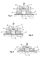
Figur 3 , jedoch mit abgeriebenem Konus an der vorderen Seite des Verbindungselementes (Zwischenstufe), - Fig. 5
- die gleiche Gestaltung, wie in
Figur 4 dargestellt, jedoch mit einer Reibschweißverbindung zwischen dem Verbindungselement und der tragenden Platte (Stufe 2), - Fig. 6
- die gleiche Gestaltung, wie in den vorherigen Figuren dargestellt, als fertiger Mehrkörperverbund.
- In der
Figur 1 ist in prinzipieller Darstellungsweise die erfindungsgemäße Vorrichtung wiedergegeben, die der Gestaltung einer Vorrichtung zum Reibschweißen von Bauteilen gemäßDE 10 2004 034 498 A1 folgt. Die erfindungsgemäße Vorrichtung weist die Steuerung 13 auf, von der ausgehend die mechanischen Teile der Vorrichtung, also insbesondere die Rotationsvorschubeinheit 11, gesteuert werden, die gegenüber einem feststehenden Rahmen 12 in ihrer Längsrichtung verschiebbar angeordnet ist. Die Rotationsvorschubeinheit 11 weist den Stößel 7 auf, der an seinem unteren Ende jeweils ein Verbindungselement 5 erfasst und unter axialem Druck in Drehung versetzt wird. Der Niederhalter 4 sorgt dafür, dass die miteinander zu verbindenden Platten, nämlich die tragende Platte 1 und die getragene Platte 2 fest aneinander liegen, während das Verbindungselement 5 unter Drehung und Druck auf die getragene Platte 2 aufgesetzt ist. Die jeweilige Lage des Stößels 7 und damit des Verbindungselementes 5 gibt die Messeinrichtung 14 an. - In der
Figur 2 sind eine tragende Platte 1 und eine darauf liegende getragenen Platte 2 dargestellt, die miteinander zu verbinden sind. Die Platte 1 besteht zum Beispiel aus Stahl, die Platte 2 aus einem Leichtmetall, zum Beispiel Aluminium. Zwischen den Platten 1 und 2 ist eine Schicht 3 eingezeichnet, durch die eine auf die tragende Platte 1 aufgebrachte Schutzschicht bzw. eine Schicht aus Verunreinigungen und/oder Klebstoff dargestellt ist. Auf die getragene Platte 2 ist die Vorrichtung zum Verbinden der beiden Platten 1 und 2 aufgesetzt, und zwar durch den Niederhalter 4, der auf die getragene Platte 2 drückt und damit diese gegen die tragende Platte 1 presst, die, was nicht dargestellt ist, in irgendeiner Weise auf einer Unterlage ruht. In dem Niederhalter 4 wird das Verbindungselement 5 geführt, das an seinem der Platte 2 abgewandten Ende einen Bund 6 aufweist, auf dessen Bedeutung weiter unten näher eingegangen wird. Auf den Bund 6 drückt der nur schematisch dargestellte Stößel 7 einer Vorrichtung zum Verbinden von zwei Platten mittels Reibschweißen (siehe zum BeispielFig. 1 ), wobei durch die Torxausnehmung 8 und einem entsprechenden aus dem Stößel 7 herausragenden Eingriff ein Drehmoment von dem sich drehenden Stößel 7 auf das Verbindungselement 5 ausgeübt werden kann. - Insoweit handelt es um eine bekannte Anordnung.
- Das Verbindungselement 5 ist in
Fig. 2 in einer Lage dargestellt, in der seine Spitze 9 gerade auf der getragenen Platte 2 aufsitzt. Dieses Aufsitzen wird von einer mit der Vorrichtung zusammenarbeitenden, inFig. 1 dargestellten Messeinrichtung 14 erkannt, und zwar durch plötzliches Festhalten des Verbindungselementes 5 bei seinem Heranbringen an die getragene Platte 2, was als Signal ausgenutzt wird, damit in der Vorrichtung automatisch eine Rotationsvorschubeinheit 11 anzutreiben, die den Stempel 7 in Drehung versetzt und nunmehr unter Druck auf das Verbindungselement 5 dieses in die getragene Platte 2 eindrückt. Bei diesem Vorgang entsteht aufgrund der Rotation des Stempels 2 und dem mitgenommenen Verbindungselement 5 eine starke Reibung an der Spitze des Verbindungselementes 5, die zu einer schnellen erheblichen Erhitzung des Materials des Verbindungselementes 5 im Bereich von dessen Spitze führt, so dass dadurch das Material der getragenen Platte 2 erweicht wird und damit die Spitze 9 des Verbindungselementes 5 in das weich gewordene Material der getragenen Platte 2 eindringt (sieheFig. 3 ). Damit wird ein nunmehr folgender Reibschweißvorgang zwischen dem Verbindungselement 5 und der tragenden Platte 1 eingeleitet. - Wenn die tragende Platte entweder mit einer Schutzschicht, mit einer Schmutzschicht und/oder Klebstoff versehen ist, was häufig nicht vermieden werden kann, so ergibt sich nach dem Vorgang des Durchdringens der getragenen Platte 2 eine Reinigung der tragenden Platte 1 insofern, als diese von ihrer Schutzschicht bzw. Schmutzschicht befreit wird, so dass sich die Materialien von der getragenen Platte 2 und der tragenden Platte 1 in dem Bereich vor der Spitze 9 des Verbindungselementes 5 miteinander verbinden können und somit eine Reibschweißverbindung erstellt werden kann.
- Die in der
Figur 4 dargestellte Gestaltung als Zwischenstufe zeigt das Verbindungselement 5 mit durch die Rotation des Verbindungselementes 5 abgetragener Spitze 9, was dazu führt, dass das Verbindungselement 5 mit seinem Schaft 10 auf die tragende Platte 1 aufsitzen kann. - Von der Messeinrichtung 14 (siehe
Fig. 1 ), die mit der Rotationsvorschubeinheit 11 in Verbindung steht, wird mit Erreichen der Stufen des Verbindungselementes 5, wie diese in denFig. 2 bis 6 dargestellt sind, signalisiert, dass nunmehr zur Herstellung einer festen Reibschweißverbindung auf das Verbindungselement bei dessen Stillstand ein erheblicher Druck ausgeübt werden kann, womit sich dessen Stirnseite mit der tragenden Platte 1 materialmäßig verbindet und somit durch Reibschweißen das Verbindungselement 5 mit der tragenden Platte 1 verbunden ist, wie dies inFig. 5 dargestellt ist. - Es kann nunmehr die Vorrichtung zum Verbinden der betreffenden Teile von der Platte 2 weggezogen werden, wobei der Bund 6 am Verbindungselement 5 dafür sorgt, dass die getragene Platte 2 weiterhin gegen die tragende Platte 1 gedrückt wird. Die endgültige Position ist in
Fig. 6 dargestellt.
Claims (10)
- Vorrichtung zum Verbinden von mindestens zwei Platten (1, 2), von denen eine tragende Platte (1) eine höhere Festigkeit als eine darauf liegende, getragene Platte (2) aufweist, mittels eines von einer Rotationsvorschubeinheit (11) in Drehung versetzten Verbindungselementes (5), das mit einem Bund (6) die getragene Platte (2) an die tragende Platte (1) drückt und mit einem Schaft (10) eine Reibschweißverbindung zu der tragenden Platte (1) herstellt, dadurch gekennzeichnet dass die Rotationsvorschubeinheit (11) mit einer Messeinrichtung (14) versehen ist, die sowohl eine von der Rotationsvorschubeinheit (11) ausgeübte Axialkraft als auch eine jeweilige Vorschublänge misst und die bei Aufsetzen des Schaftes des Verbindungselementes (5) auf die getragene Platte (2) den dabei auftretenden Druckanstieg signalisiert, der damit die Rotationsvorschubeinheit (11), deren Vorschub auf mindestens drei aufeinander folgende Verbindungsstufen einstellbar ist, fortschaltet, wobei die erste Stufe auf das Durchdringen der getragenen Platte (2), die zweite Stufe auf das Reibschweißen des Schaftes (10) mit der tragenden Platte (1) eingestellt ist und die dritte Stufe den Reibschweißvorgang durch eine Erhöhung der Axialkraft des Verbindungselementes (5) auf die tragende Platte (1) beendet.
- Vorrichtung nach Patentanspruch 1, dadurch gekennzeichnet dass zwischen der ersten und zweiten Stufe in einer Zwischenstufe die Rotationsvorschubeinheit (11) mit gegenüber der ersten Stufe veränderter Drehzahl und veränderter Axialkraft dreht.
- Vorrichtung zum Verbinden von mindestens zwei Platten (1, 2) nach Anspruch 1, dadurch gekennzeichnet, dass die tragende Platte (1) aus Stahl besteht.
- Vorrichtung zum Verbinden von mindestens zwei Platten (1, 2) nach Anspruch 1, dadurch gekennzeichnet, dass die getragene Platte (2) aus einem Leichtmetall besteht.
- Vorrichtung zum Verbinden von mindestens zwei Platten (1, 2) nach Anspruch 1, dadurch gekennzeichnet, dass das Verbindungselement (5) aus Stahl besteht.
- Vorrichtung zum Verbinden von mindestens zwei Platten (1, 2) nach Anspruch 1, dadurch gekennzeichnet, dass das Verbindungselement (5) aus Aluminium besteht.
- Vorrichtung zum Verbinden von mindestens zwei Platten (1, 2) nach Anspruch 1, dadurch gekennzeichnet, dass die Platten und das Verbindungselement aus Kunststoff bestehen.
- Vorrichtung nach einem der vorangehenden Ansprüche, dadurch gekennzeichnet, dass die Rotationsvorschubeinheit (11) in der ersten Stufe auf die Dicke der getragenen Platte (2) mit einer Drehzahl und Axialkraft eingestellt ist, bei der das Material der getragenen Platte (2) im Bereich des Verbindungselementes (5) fließt.
- Vorrichtung nach einem der vorangehenden Ansprüche, dadurch gekennzeichnet, dass die Rotationsvorschubeinheit (11) in der zweiten Stufe mit gegenüber der ersten Stufe verringerter Drehzahl und erhöhter Axialkraft dreht.
- Vorrichtung nach einem der vorangehenden Ansprüche, dadurch gekennzeichnet, dass in der dritten Stufe die Rotation des Rotationsvorschubs auf 0 eingestellt ist und die Rotationsvorschubeinheit (11) unter Druck auf das Verbindungselement (5) dessen Stauchung gegen die tragende Platte (1)bewirkt.
Applications Claiming Priority (1)
| Application Number | Priority Date | Filing Date | Title |
|---|---|---|---|
| DE102009038697A DE102009038697A1 (de) | 2009-08-24 | 2009-08-24 | Vorrichtung zum Verbinden von mindestens zwei Platten |
Publications (2)
| Publication Number | Publication Date |
|---|---|
| EP2289659A1 true EP2289659A1 (de) | 2011-03-02 |
| EP2289659B1 EP2289659B1 (de) | 2013-07-17 |
Family
ID=43086707
Family Applications (1)
| Application Number | Title | Priority Date | Filing Date |
|---|---|---|---|
| EP10172958.0A Active EP2289659B1 (de) | 2009-08-24 | 2010-08-16 | Vorrichtung zum Reibschweissverbinden von mindestens zwei Platten durch ein Verbindungselement mit einer Einrichtung zum Messen der ausgeübten Kraft und der Vorschublänge während des Verbindens |
Country Status (8)
| Country | Link |
|---|---|
| US (1) | US8752603B2 (de) |
| EP (1) | EP2289659B1 (de) |
| JP (1) | JP5757701B2 (de) |
| CN (1) | CN101992349B (de) |
| BR (1) | BRPI1003208B1 (de) |
| DE (1) | DE102009038697A1 (de) |
| ES (1) | ES2431587T3 (de) |
| MX (1) | MX2010009267A (de) |
Cited By (2)
| Publication number | Priority date | Publication date | Assignee | Title |
|---|---|---|---|---|
| DE102015202074A1 (de) | 2015-02-05 | 2016-08-11 | Ejot Gmbh & Co. Kg | Verbindungselement zur Herstellung einer Bauteilverbindung |
| EP3348347A1 (de) * | 2017-01-17 | 2018-07-18 | Weber Schraubautomaten GmbH | Verfahren und vorrichtung zum setzen einer schraube |
Families Citing this family (19)
| Publication number | Priority date | Publication date | Assignee | Title |
|---|---|---|---|---|
| JP5688568B2 (ja) * | 2008-07-15 | 2015-03-25 | 山野井精機株式会社 | 被加工金属部材に突起を形成する突起形成方法 |
| ES2435734B1 (es) * | 2012-05-16 | 2014-10-03 | Loxin 2002, S.L. | Electromandrino con control de fuerza axial para soldadura por fricción y otras aplicaciones |
| DE202012011021U1 (de) | 2012-11-16 | 2014-02-17 | Ejot Gmbh & Co. Kg | Setzwerkzeugsytem |
| DE102014101627A1 (de) * | 2014-02-10 | 2015-08-13 | Ms Spaichingen Gmbh | Gestell für eine Maschine |
| DE102014105702A1 (de) * | 2014-04-23 | 2015-10-29 | Weber Schraubautomaten Gmbh | Vorrichtung zum Setzen eines Setzelements in einem Bauteil |
| DE102014218975A1 (de) * | 2014-09-22 | 2016-03-24 | Bayerische Motoren Werke Aktiengesellschaft | Reibelementschweißverfahren |
| DE102014220673A1 (de) * | 2014-10-13 | 2016-04-14 | Zf Friedrichshafen Ag | Achsgehäuse mit reibverschweißtem Bolzen |
| US10628894B1 (en) | 2015-01-28 | 2020-04-21 | Intuit Inc. | Method and system for providing personalized responses to questions received from a user of an electronic tax return preparation system |
| US10937109B1 (en) | 2016-01-08 | 2021-03-02 | Intuit Inc. | Method and technique to calculate and provide confidence score for predicted tax due/refund |
| DE102016205924A1 (de) * | 2016-04-08 | 2017-10-12 | Ford Global Technologies, Llc | Verfahren zum Herstellen einer Hybridverbindung sowie Vorrichtung dazu |
| DE102016107961A1 (de) * | 2016-04-28 | 2017-11-02 | Ejot Gmbh & Co. Kg | Verfahren und Vorrichtung zum Verbinden zweier plattenartiger Bauteile |
| DE102016112297A1 (de) * | 2016-07-05 | 2018-01-11 | Ejot Gmbh & Co. Kg | Vorrichtung zur Verbindung von zwei Bauteillagen |
| US10478916B2 (en) * | 2017-11-02 | 2019-11-19 | GM Global Technology Operations LLC | Method and apparatus for joining components with friction pins |
| US11697173B2 (en) | 2018-05-09 | 2023-07-11 | Brigham Young University | Systems and methods for friction bit joining |
| CN112739486B (zh) * | 2018-09-26 | 2022-08-19 | 日本制铁株式会社 | 接合结构、接合方法以及汽车用构件 |
| EP3984684A4 (de) * | 2019-06-17 | 2022-11-02 | Nippon Steel Corporation | Geklebte verbindung und element für ein kraftfahrzeug |
| WO2020256030A1 (ja) | 2019-06-17 | 2020-12-24 | 日本製鉄株式会社 | 接合継手および接合継手の製造方法 |
| US20220324051A1 (en) * | 2021-04-08 | 2022-10-13 | Ford Global Technologies, Llc | Adaptive friction element weld process and control |
| CN113714600B (zh) * | 2021-11-01 | 2021-12-31 | 龙口市龙兴达电器有限公司 | 一种工业风扇网罩自动焊接设备 |
Citations (3)
| Publication number | Priority date | Publication date | Assignee | Title |
|---|---|---|---|---|
| US3477115A (en) * | 1967-03-17 | 1969-11-11 | Caterpillar Tractor Co | Method of fastening parts by friction welding |
| DE19620814A1 (de) | 1996-05-23 | 1997-11-27 | Emhart Inc | Mehrkörperverbund und Reibschweißverfahren zu seiner Herstellung |
| DE102004034498A1 (de) | 2004-07-16 | 2006-02-16 | Ejot Gmbh & Co. Kg | Verfahren zum Reibschweißen von Bauteilen |
Family Cites Families (9)
| Publication number | Priority date | Publication date | Assignee | Title |
|---|---|---|---|---|
| US3993519A (en) * | 1975-11-07 | 1976-11-23 | Olsen Manufacturing Company, Inc. | Spin welding apparatus and method |
| US5108539A (en) * | 1990-04-23 | 1992-04-28 | Shell Oil Company | Apparatus for the resilient spinwelding of thermoplastic articles |
| US6050475A (en) | 1998-05-29 | 2000-04-18 | Mcdonnell Douglas Corporation | Method and apparatus for controlling downforce during friction stir welding |
| AU733140B2 (en) | 1998-09-29 | 2001-05-10 | Hitachi Limited | A friction stir welding method |
| US6296726B1 (en) * | 2000-06-13 | 2001-10-02 | Silgan Containers Corporation | Method and apparatus for spin welding container closures |
| DE10330188A1 (de) * | 2003-07-03 | 2005-02-03 | Kuka Schweissanlagen Gmbh | Verfahren und Vorrichtung zum Pressschweißen |
| US20060213954A1 (en) * | 2005-03-23 | 2006-09-28 | Michael Ruther | Method and joining element for joining workpieces |
| JP5060984B2 (ja) | 2008-02-07 | 2012-10-31 | 株式会社豊田自動織機 | 摩擦圧接装置 |
| US20100072261A1 (en) * | 2008-09-25 | 2010-03-25 | Marcio Fernando Cruz | Friction stir welding spindle downforce and other control techniques, systems and methods |
-
2009
- 2009-08-24 DE DE102009038697A patent/DE102009038697A1/de active Pending
-
2010
- 2010-08-04 JP JP2010175515A patent/JP5757701B2/ja active Active
- 2010-08-12 US US12/854,958 patent/US8752603B2/en active Active
- 2010-08-16 EP EP10172958.0A patent/EP2289659B1/de active Active
- 2010-08-16 ES ES10172958T patent/ES2431587T3/es active Active
- 2010-08-20 CN CN201010265058.0A patent/CN101992349B/zh active Active
- 2010-08-23 MX MX2010009267A patent/MX2010009267A/es active IP Right Grant
- 2010-08-23 BR BRPI1003208-8A patent/BRPI1003208B1/pt active IP Right Grant
Patent Citations (3)
| Publication number | Priority date | Publication date | Assignee | Title |
|---|---|---|---|---|
| US3477115A (en) * | 1967-03-17 | 1969-11-11 | Caterpillar Tractor Co | Method of fastening parts by friction welding |
| DE19620814A1 (de) | 1996-05-23 | 1997-11-27 | Emhart Inc | Mehrkörperverbund und Reibschweißverfahren zu seiner Herstellung |
| DE102004034498A1 (de) | 2004-07-16 | 2006-02-16 | Ejot Gmbh & Co. Kg | Verfahren zum Reibschweißen von Bauteilen |
Non-Patent Citations (1)
| Title |
|---|
| A. W. E. NENTWIG ET AL: "UNTERSUCHUNG ZUR ANWENDBARKEIT DES REIBBOLZENSCHWEISSENS", SCHWEISSEN UND SCHNEIDEN, DVS VERLAG, DUSSELDORF, DE, vol. 46, no. 7, 1 July 1994 (1994-07-01), pages 319 - 324, XP000457270, ISSN: 0036-7184 * |
Cited By (4)
| Publication number | Priority date | Publication date | Assignee | Title |
|---|---|---|---|---|
| DE102015202074A1 (de) | 2015-02-05 | 2016-08-11 | Ejot Gmbh & Co. Kg | Verbindungselement zur Herstellung einer Bauteilverbindung |
| US10710193B2 (en) | 2015-02-05 | 2020-07-14 | Ejot Gmbh & Co. Kg | Connecting element for producing a friction-welding connection |
| EP3348347A1 (de) * | 2017-01-17 | 2018-07-18 | Weber Schraubautomaten GmbH | Verfahren und vorrichtung zum setzen einer schraube |
| US10981213B2 (en) | 2017-01-17 | 2021-04-20 | Weber Schraubautomaten Gmbh | Method and apparatus for setting a screw |
Also Published As
| Publication number | Publication date |
|---|---|
| BRPI1003208B1 (pt) | 2018-02-06 |
| US20110073258A1 (en) | 2011-03-31 |
| US8752603B2 (en) | 2014-06-17 |
| JP5757701B2 (ja) | 2015-07-29 |
| JP2011062748A (ja) | 2011-03-31 |
| ES2431587T3 (es) | 2013-11-27 |
| MX2010009267A (es) | 2011-08-05 |
| CN101992349A (zh) | 2011-03-30 |
| CN101992349B (zh) | 2015-05-20 |
| DE102009038697A1 (de) | 2011-03-17 |
| BRPI1003208A2 (pt) | 2012-05-02 |
| EP2289659B1 (de) | 2013-07-17 |
Similar Documents
| Publication | Publication Date | Title |
|---|---|---|
| EP2289659B1 (de) | Vorrichtung zum Reibschweissverbinden von mindestens zwei Platten durch ein Verbindungselement mit einer Einrichtung zum Messen der ausgeübten Kraft und der Vorschublänge während des Verbindens | |
| DE102008044451B4 (de) | Konduktives Bolzenschweißen | |
| EP1776205B1 (de) | Verfahren zum reibschweissen von bauteilen | |
| AT518154B1 (de) | Verfahren und Vorrichtung zum Trennen eines Werkstückes | |
| DE102010020569A1 (de) | Verfahren zum thermischen Fügen von zwei Bauelementen | |
| WO2017063761A1 (de) | Folie zur reibungserhöhung zwischen zwei kraftschlüssig verbundenen bauteilen | |
| WO1998004381A1 (de) | Verfahren zum verbinden eines plastifizierbaren werkstücks mit einem anderen werkstück | |
| WO2005063421A1 (de) | Verfahren und vorrichtung zum herstellen eines zylindrischen hohlkörpers aus einem rohling | |
| DE102014001690B4 (de) | Verfahren zum Fügen eines Metallbauteils mit einem Kunststoffbauteil | |
| DE102015213633B3 (de) | Verfahren zum Fügen von mindestens zwei Bauteilen mittels Reibpunktschweißen und einem als Fügeelement ausgebildeten Reibelement sowie Fügevorrichtung | |
| DE102011051301A1 (de) | Verfahren und Vorrichtung zur Herstellung einer Metall-Kunststoff-Verbindung | |
| DE102010053119A1 (de) | Verfahren zur Herstellung einer Gewindespindel mit großem Lagersitz | |
| EP2837536B1 (de) | Vorrichtung zum Entmanteln eines Rohrendes einer mit einer Kunststoffbeschichtung beschichteten Brems- oder Kraftstoffleitung | |
| DE102007036972A1 (de) | Verfahren zum Fügen sowie Fügeverbindung von zwei Bauteilen aus Metallwerkstoff | |
| DE102011102288B4 (de) | Vorrichtung und Verfahren zur Herstellung eines Stirnrads mit einer Schrägverzahnung | |
| EP3055117B1 (de) | Vorrichtung zum fixieren von extrudiertem kunststoffprofil | |
| DE102011109805B3 (de) | Verbindung zumindest zweier aneinander anliegender Bauteile | |
| DE2157874B2 (de) | Vorrichtung zur Kaltherstellung schrägverzahnter Zahnradrohlinge | |
| WO2014166481A1 (de) | Verfahren und vorrichtung zur presssitz-montage eines ringförmigen bauteils | |
| DE19724657C2 (de) | Verfahren und Vorrichtung zum Herstellen eines rotationssymmetrischen Körpers | |
| EP3884254B1 (de) | Verfahren zur herstellung einer hochdruck-hydraulikleitung sowie radialpresse zur durchführung des verfahrens | |
| DE102017213233A1 (de) | Stanznietvorrichtung und Verfahren zum Verbinden von Bauteilen | |
| EP0765729B1 (de) | Teil-Schneckenwelle für eine Schneckenmaschine und Verfahren zu ihrer Herstellung | |
| DE102018112193B4 (de) | Verfahren zur Herstellung einer Nietverbindung | |
| EP3446807B1 (de) | Verfahren zur herstellung eines sacklochs |
Legal Events
| Date | Code | Title | Description |
|---|---|---|---|
| PUAI | Public reference made under article 153(3) epc to a published international application that has entered the european phase |
Free format text: ORIGINAL CODE: 0009012 |
|
| AK | Designated contracting states |
Kind code of ref document: A1 Designated state(s): AL AT BE BG CH CY CZ DE DK EE ES FI FR GB GR HR HU IE IS IT LI LT LU LV MC MK MT NL NO PL PT RO SE SI SK SM TR |
|
| AX | Request for extension of the european patent |
Extension state: BA ME RS |
|
| 17P | Request for examination filed |
Effective date: 20110902 |
|
| GRAP | Despatch of communication of intention to grant a patent |
Free format text: ORIGINAL CODE: EPIDOSNIGR1 |
|
| GRAS | Grant fee paid |
Free format text: ORIGINAL CODE: EPIDOSNIGR3 |
|
| GRAA | (expected) grant |
Free format text: ORIGINAL CODE: 0009210 |
|
| AK | Designated contracting states |
Kind code of ref document: B1 Designated state(s): AL AT BE BG CH CY CZ DE DK EE ES FI FR GB GR HR HU IE IS IT LI LT LU LV MC MK MT NL NO PL PT RO SE SI SK SM TR |
|
| AX | Request for extension of the european patent |
Extension state: BA ME RS |
|
| REG | Reference to a national code |
Ref country code: GB Ref legal event code: FG4D Free format text: NOT ENGLISH |
|
| REG | Reference to a national code |
Ref country code: CH Ref legal event code: EP |
|
| REG | Reference to a national code |
Ref country code: IE Ref legal event code: FG4D Free format text: LANGUAGE OF EP DOCUMENT: GERMAN |
|
| REG | Reference to a national code |
Ref country code: AT Ref legal event code: REF Ref document number: 621866 Country of ref document: AT Kind code of ref document: T Effective date: 20130815 |
|
| REG | Reference to a national code |
Ref country code: DE Ref legal event code: R096 Ref document number: 502010004024 Country of ref document: DE Effective date: 20130912 |
|
| REG | Reference to a national code |
Ref country code: ES Ref legal event code: FG2A Ref document number: 2431587 Country of ref document: ES Kind code of ref document: T3 Effective date: 20131127 |
|
| REG | Reference to a national code |
Ref country code: NL Ref legal event code: VDEP Effective date: 20130717 |
|
| REG | Reference to a national code |
Ref country code: LT Ref legal event code: MG4D |
|
| REG | Reference to a national code |
Ref country code: SK Ref legal event code: T3 Ref document number: E 15015 Country of ref document: SK |
|
| PG25 | Lapsed in a contracting state [announced via postgrant information from national office to epo] |
Ref country code: SE Free format text: LAPSE BECAUSE OF FAILURE TO SUBMIT A TRANSLATION OF THE DESCRIPTION OR TO PAY THE FEE WITHIN THE PRESCRIBED TIME-LIMIT Effective date: 20130717 Ref country code: IS Free format text: LAPSE BECAUSE OF FAILURE TO SUBMIT A TRANSLATION OF THE DESCRIPTION OR TO PAY THE FEE WITHIN THE PRESCRIBED TIME-LIMIT Effective date: 20131117 Ref country code: LT Free format text: LAPSE BECAUSE OF FAILURE TO SUBMIT A TRANSLATION OF THE DESCRIPTION OR TO PAY THE FEE WITHIN THE PRESCRIBED TIME-LIMIT Effective date: 20130717 Ref country code: PT Free format text: LAPSE BECAUSE OF FAILURE TO SUBMIT A TRANSLATION OF THE DESCRIPTION OR TO PAY THE FEE WITHIN THE PRESCRIBED TIME-LIMIT Effective date: 20131118 Ref country code: NO Free format text: LAPSE BECAUSE OF FAILURE TO SUBMIT A TRANSLATION OF THE DESCRIPTION OR TO PAY THE FEE WITHIN THE PRESCRIBED TIME-LIMIT Effective date: 20131017 Ref country code: HR Free format text: LAPSE BECAUSE OF FAILURE TO SUBMIT A TRANSLATION OF THE DESCRIPTION OR TO PAY THE FEE WITHIN THE PRESCRIBED TIME-LIMIT Effective date: 20130717 Ref country code: CY Free format text: LAPSE BECAUSE OF FAILURE TO SUBMIT A TRANSLATION OF THE DESCRIPTION OR TO PAY THE FEE WITHIN THE PRESCRIBED TIME-LIMIT Effective date: 20130710 |
|
| BERE | Be: lapsed |
Owner name: EJOT G.M.B.H. & CO. KG Effective date: 20130831 |
|
| PG25 | Lapsed in a contracting state [announced via postgrant information from national office to epo] |
Ref country code: LV Free format text: LAPSE BECAUSE OF FAILURE TO SUBMIT A TRANSLATION OF THE DESCRIPTION OR TO PAY THE FEE WITHIN THE PRESCRIBED TIME-LIMIT Effective date: 20130717 Ref country code: SI Free format text: LAPSE BECAUSE OF FAILURE TO SUBMIT A TRANSLATION OF THE DESCRIPTION OR TO PAY THE FEE WITHIN THE PRESCRIBED TIME-LIMIT Effective date: 20130717 Ref country code: GR Free format text: LAPSE BECAUSE OF FAILURE TO SUBMIT A TRANSLATION OF THE DESCRIPTION OR TO PAY THE FEE WITHIN THE PRESCRIBED TIME-LIMIT Effective date: 20131018 Ref country code: NL Free format text: LAPSE BECAUSE OF FAILURE TO SUBMIT A TRANSLATION OF THE DESCRIPTION OR TO PAY THE FEE WITHIN THE PRESCRIBED TIME-LIMIT Effective date: 20130717 Ref country code: FI Free format text: LAPSE BECAUSE OF FAILURE TO SUBMIT A TRANSLATION OF THE DESCRIPTION OR TO PAY THE FEE WITHIN THE PRESCRIBED TIME-LIMIT Effective date: 20130717 Ref country code: PL Free format text: LAPSE BECAUSE OF FAILURE TO SUBMIT A TRANSLATION OF THE DESCRIPTION OR TO PAY THE FEE WITHIN THE PRESCRIBED TIME-LIMIT Effective date: 20130717 |
|
| PG25 | Lapsed in a contracting state [announced via postgrant information from national office to epo] |
Ref country code: CY Free format text: LAPSE BECAUSE OF FAILURE TO SUBMIT A TRANSLATION OF THE DESCRIPTION OR TO PAY THE FEE WITHIN THE PRESCRIBED TIME-LIMIT Effective date: 20130717 |
|
| PG25 | Lapsed in a contracting state [announced via postgrant information from national office to epo] |
Ref country code: DK Free format text: LAPSE BECAUSE OF FAILURE TO SUBMIT A TRANSLATION OF THE DESCRIPTION OR TO PAY THE FEE WITHIN THE PRESCRIBED TIME-LIMIT Effective date: 20130717 Ref country code: MC Free format text: LAPSE BECAUSE OF FAILURE TO SUBMIT A TRANSLATION OF THE DESCRIPTION OR TO PAY THE FEE WITHIN THE PRESCRIBED TIME-LIMIT Effective date: 20130717 Ref country code: EE Free format text: LAPSE BECAUSE OF FAILURE TO SUBMIT A TRANSLATION OF THE DESCRIPTION OR TO PAY THE FEE WITHIN THE PRESCRIBED TIME-LIMIT Effective date: 20130717 Ref country code: RO Free format text: LAPSE BECAUSE OF FAILURE TO SUBMIT A TRANSLATION OF THE DESCRIPTION OR TO PAY THE FEE WITHIN THE PRESCRIBED TIME-LIMIT Effective date: 20130717 |
|
| REG | Reference to a national code |
Ref country code: IE Ref legal event code: MM4A |
|
| PLBE | No opposition filed within time limit |
Free format text: ORIGINAL CODE: 0009261 |
|
| STAA | Information on the status of an ep patent application or granted ep patent |
Free format text: STATUS: NO OPPOSITION FILED WITHIN TIME LIMIT |
|
| PG25 | Lapsed in a contracting state [announced via postgrant information from national office to epo] |
Ref country code: BE Free format text: LAPSE BECAUSE OF NON-PAYMENT OF DUE FEES Effective date: 20130831 |
|
| 26N | No opposition filed |
Effective date: 20140422 |
|
| PG25 | Lapsed in a contracting state [announced via postgrant information from national office to epo] |
Ref country code: IE Free format text: LAPSE BECAUSE OF NON-PAYMENT OF DUE FEES Effective date: 20130816 |
|
| REG | Reference to a national code |
Ref country code: DE Ref legal event code: R097 Ref document number: 502010004024 Country of ref document: DE Effective date: 20140422 |
|
| REG | Reference to a national code |
Ref country code: CH Ref legal event code: PL |
|
| PG25 | Lapsed in a contracting state [announced via postgrant information from national office to epo] |
Ref country code: LI Free format text: LAPSE BECAUSE OF NON-PAYMENT OF DUE FEES Effective date: 20140831 Ref country code: CH Free format text: LAPSE BECAUSE OF NON-PAYMENT OF DUE FEES Effective date: 20140831 |
|
| PG25 | Lapsed in a contracting state [announced via postgrant information from national office to epo] |
Ref country code: SM Free format text: LAPSE BECAUSE OF FAILURE TO SUBMIT A TRANSLATION OF THE DESCRIPTION OR TO PAY THE FEE WITHIN THE PRESCRIBED TIME-LIMIT Effective date: 20130717 |
|
| PG25 | Lapsed in a contracting state [announced via postgrant information from national office to epo] |
Ref country code: MT Free format text: LAPSE BECAUSE OF FAILURE TO SUBMIT A TRANSLATION OF THE DESCRIPTION OR TO PAY THE FEE WITHIN THE PRESCRIBED TIME-LIMIT Effective date: 20130717 Ref country code: TR Free format text: LAPSE BECAUSE OF FAILURE TO SUBMIT A TRANSLATION OF THE DESCRIPTION OR TO PAY THE FEE WITHIN THE PRESCRIBED TIME-LIMIT Effective date: 20130717 |
|
| PG25 | Lapsed in a contracting state [announced via postgrant information from national office to epo] |
Ref country code: HU Free format text: LAPSE BECAUSE OF FAILURE TO SUBMIT A TRANSLATION OF THE DESCRIPTION OR TO PAY THE FEE WITHIN THE PRESCRIBED TIME-LIMIT; INVALID AB INITIO Effective date: 20100816 Ref country code: BG Free format text: LAPSE BECAUSE OF FAILURE TO SUBMIT A TRANSLATION OF THE DESCRIPTION OR TO PAY THE FEE WITHIN THE PRESCRIBED TIME-LIMIT Effective date: 20130717 Ref country code: LU Free format text: LAPSE BECAUSE OF NON-PAYMENT OF DUE FEES Effective date: 20130816 Ref country code: MK Free format text: LAPSE BECAUSE OF FAILURE TO SUBMIT A TRANSLATION OF THE DESCRIPTION OR TO PAY THE FEE WITHIN THE PRESCRIBED TIME-LIMIT Effective date: 20130717 |
|
| REG | Reference to a national code |
Ref country code: FR Ref legal event code: PLFP Year of fee payment: 6 |
|
| REG | Reference to a national code |
Ref country code: FR Ref legal event code: PLFP Year of fee payment: 7 |
|
| REG | Reference to a national code |
Ref country code: FR Ref legal event code: PLFP Year of fee payment: 8 |
|
| REG | Reference to a national code |
Ref country code: FR Ref legal event code: PLFP Year of fee payment: 9 |
|
| PG25 | Lapsed in a contracting state [announced via postgrant information from national office to epo] |
Ref country code: AL Free format text: LAPSE BECAUSE OF FAILURE TO SUBMIT A TRANSLATION OF THE DESCRIPTION OR TO PAY THE FEE WITHIN THE PRESCRIBED TIME-LIMIT Effective date: 20130717 |
|
| PGFP | Annual fee paid to national office [announced via postgrant information from national office to epo] |
Ref country code: IT Payment date: 20230831 Year of fee payment: 14 Ref country code: GB Payment date: 20230824 Year of fee payment: 14 Ref country code: ES Payment date: 20230918 Year of fee payment: 14 Ref country code: CZ Payment date: 20230803 Year of fee payment: 14 Ref country code: AT Payment date: 20230818 Year of fee payment: 14 |
|
| PGFP | Annual fee paid to national office [announced via postgrant information from national office to epo] |
Ref country code: SK Payment date: 20230807 Year of fee payment: 14 Ref country code: FR Payment date: 20230821 Year of fee payment: 14 Ref country code: DE Payment date: 20230830 Year of fee payment: 14 |