EP2289386B1 - Geschirrspülmaschine, insbesondere Haushaltsgeschirrspülmaschine - Google Patents
Geschirrspülmaschine, insbesondere Haushaltsgeschirrspülmaschine Download PDFInfo
- Publication number
- EP2289386B1 EP2289386B1 EP10172898.8A EP10172898A EP2289386B1 EP 2289386 B1 EP2289386 B1 EP 2289386B1 EP 10172898 A EP10172898 A EP 10172898A EP 2289386 B1 EP2289386 B1 EP 2289386B1
- Authority
- EP
- European Patent Office
- Prior art keywords
- door
- closing
- closing piston
- closing plunger
- dishwasher
- Prior art date
- Legal status (The legal status is an assumption and is not a legal conclusion. Google has not performed a legal analysis and makes no representation as to the accuracy of the status listed.)
- Active
Links
Images


Classifications
-
- A—HUMAN NECESSITIES
- A47—FURNITURE; DOMESTIC ARTICLES OR APPLIANCES; COFFEE MILLS; SPICE MILLS; SUCTION CLEANERS IN GENERAL
- A47L—DOMESTIC WASHING OR CLEANING; SUCTION CLEANERS IN GENERAL
- A47L15/00—Washing or rinsing machines for crockery or tableware
- A47L15/42—Details
- A47L15/4251—Details of the casing
- A47L15/4257—Details of the loading door
- A47L15/4259—Arrangements of locking or security/safety devices for doors, e.g. door latches, switch to stop operation when door is open
Definitions
- the present invention relates to a dishwasher, in particular domestic dishwasher, with a washing container whose feed opening can be closed by a door, wherein the door can be locked in its Sch formatdposition by means of a door lock.
- Dishwashers in particular domestic dishwashers, generally have a bottom assembly, also referred to as a base support, and a washing container mounted on the bottom assembly.
- the rinsing container may comprise, in addition to an inner housing, an outer housing, also referred to as a rinsing container frame element.
- the bottom module is arranged below the washing container and makes contact with a supporting element or ground, in particular to the ground forth.
- the washing compartment has on one side a charging opening for charging the one or more dish racks provided in the washing compartment of the washing compartment.
- the loading opening is opened for loading the one or more dish racks by a door attached to the dishwasher and closed for operation of the dishwasher by the door attached to the dishwasher.
- the feed opening is usually arranged at the front, so that the door is usually fastened in the lower region of the washing container, in particular on the base assembly of the domestic dishwasher, pivotably or optionally also extendable, similar to a drawer.
- From the DE 38 42 639 A1 is a device for locking a door on a dishwasher, with a bordering the edge of the door frame known, in which on the edge of the door a recess is mounted and a closing part resiliently biased held on the frame and when closing the door in the recess of the edge is inserted.
- the object of the invention is to provide a dishwasher, in particular a household dishwasher, which is designed and manufactured as simply as possible.
- the door lock of the dishwasher should be simple, easy to manufacture and easy to mount on the dishwasher.
- one or more door locks each comprise a linearly displaceable closing piston and a recess for receiving at least one locking end of the closing piston, that the closing piston by means of an actuating force against one on the Closing piston acting clamping force is linearly displaceable, wherein the actuating force is generated on the closing piston by cooperation of the closing piston and the recess by means of at least one actuating portion on the closing piston and / or at least one operating portion of the recess, and that in the closing end position of the door at least the locking of the Closing piston engages due to the force acting on the closing piston clamping force to lock the door in the recess.
- a dishwasher in particular domestic dishwasher, with a washing container whose feed opening is closed by a door, wherein the door is locked in its Sch detaildposition by means of a door lock, wherein one or more door locks each have a linearly displaceable closing piston and a respective recess for receiving at least one Arretierendes Include closing piston, wherein the closing piston by means of an actuating force against a force acting on the closing piston clamping force is linearly displaceable, wherein the actuating force on the closing piston by cooperation of the closing piston and the recess by means of at least one actuating portion on the closing piston and / or at least one actuating portion of the recess is generated, and at least in the closing end position of the door at least the locking end of the closing piston due to the force acting on the closing piston clamping force m locking the door engages in the recess, can be particularly easily formed and manufactured.
- that Door lock the dishwasher can be easily formed, easy to produce and easy to be mounted on the dishwasher.
- the door lock comprises only one linearly or longitudinally displaceable closing piston and a recess.
- the door lock can be structurally simple. In the closing end position of the closing piston, this is held by the force acting on the closing piston clamping force and the walls of the recesses, which exert a frictional resistance to the closing piston upon contact of the closing piston.
- the closing piston is only linearly or longitudinally displaced. For this purpose, it is displaced linearly or longitudinally against a clamping force acting on the closing piston. The required for opening the door operating force is generated by the interaction of the closing piston and the recess.
- an actuating region is provided on the closing piston and / or on the depression, via which the closing piston and the depression can come into contact and via which an actuating force can be generated.
- a tightening force is exerted, through which the closing piston and the depression touch.
- an actuating region of the closing piston contacts the depression or the wall of the depression and / or an actuating region of the depression, in particular a region of the wall of the depression, the closing piston, in particular the locking end of the closing piston.
- the depression may in particular be a recess, for example a depression or an impression, or a hole.
- the recess is designed so that it can accommodate at least the locking end of the closing piston. That is, at least the locking end of the closing piston dips into the recess to lock the closing piston in the recess.
- the closing piston is in particular a locking element.
- the closing piston may also be referred to as a closing cam.
- An actuating region is in particular a region of the closing piston or depression, which by virtue of its design or shape in interaction with a counterpart, ie either the closing piston or the recess, can exert an actuating force such that the closing piston counteracts the locking piston acting clamping force can be moved linearly.
- the at least one actuating region is arranged on the closing piston and / or the at least one actuating region on the depression in such a way that, when the closing piston and the depression interact, the actuating force of the clamping force acting on the closing piston is directed counter to.
- An actuating region is characterized in particular by the fact that it comprises a surface which extends neither parallel nor perpendicular to the direction of the clamping force on the closing piston.
- the actuating region preferably extends inclined to the longitudinal axis of the linear guide of the closing piston, wherein the actuating region is arranged in particular at an angle that is greater than 0 ° and less than 90 ° to the longitudinal axis of the linear guide of the closing piston. If the actuating region is curved, the tangent at the point of contact between the closing piston and the recess is inclined, in particular at an angle which is greater than 0 ° and less than 90 °, to the longitudinal axis of the linear guidance of the closing piston, ie the direction of the clamping force , which acts on the closing piston.
- the actuating force required for the displacement of the closing piston can be generated by the cooperation of the closing piston and the recess by means of at least one actuating region on the closing piston and / or at least one actuating region on the depression, there are no additional components, in particular a device such as a lever or pulling means required, via which a force can be applied such that the closing piston is displaced against the clamping force acting on it. That is, an operator of the dishwasher can only by pulling on the door, ie by applying a tightening force on the door, they open.
- a portion of the tightening force exerted by the operator on the door is converted by the cooperation of the closing piston and the recess by means of at least one actuating portion on the closing piston and / or recess in an actuating force by which the closing piston against the clamping force acting on it can be moved.
- a second part of the tightening force serves to overcome the friction which acts on the contact surface between the closing piston and the recess when the closing piston and the recess cooperate. Due to the interaction of the closing piston and the depression, frictional resistance occurs at the contact surface between the closing piston and the depression. The friction on the contact surface inhibits the relative movement between the closing piston and the recess.
- the frictional force acts parallel to the contact surface between the closing piston and the recess and is opposite to the movement and thus also the force causing the movement.
- the closing piston is securely held in the recess by the clamping force and the frictional force to be overcome when the closing piston contacts the recess.
- the door lock and thus the dishwasher are structurally lightweight.
- a "Hommer Profy” is provided that manages with very simple components.
- the closing piston is arranged in or on the washing container, in particular a Spül relieerrahmenelement, and that the recess in or on the frame of the door, in particular in or on the frame of an inner door the door; is provided.
- the door of the dishwasher may have an interior door facing the washing compartment interior and an exterior door facing away from the washing compartment interior.
- the closing piston can be arranged, for example, in a recess in the washing container, in particular a washing container frame element.
- the closing piston may be arranged, for example, at least partially in a recess in a side wall, in a cover wall and / or in a bottom wall, in particular a bottom trough, of the washing compartment.
- the closing piston can be arranged on the rinsing container, in particular a rinsing container frame element. That is, the closing piston can be arranged for example on a side wall, a top wall and / or a bottom wall, in particular a bottom trough, of the washing compartment.
- the closing piston is arranged in particular in or on the inside of the washing container, in particular of the washing container frame element, so that it can be displaced in the direction of the loading opening.
- the closing piston is arranged exclusively linearly or longitudinally displaceable.
- the closing piston is preferably held displaceably along a linear guide.
- the closing piston is preferably in the recess in the front edge region of the washing container, in particular its front edge element or its front Spül disposerrahmenelement, arranged that at least the locking of the closing piston can protrude due to the force acting on it clamping force from the recess to engage for locking the door of the dishwasher in a corresponding recess.
- the front edge region of the washing container can in particular be stiffened. For this purpose, if appropriate, in addition, in particular, a front edge element or Spül relieerrahmenelement be provided.
- the edge element or Spül relierrahmenelement encloses in particular at least partially the feed opening of the dishwasher.
- the closing piston is arranged in or on the front edge region of the washing container, in particular the front edge element or Spül relierrahmenelement, the recess in or on the frame of the door, in particular in or on the frame of an inner door of the door is provided.
- the depression is arranged in the frame of the door, in particular in the frame of the inner door, that in the closing end position of the door, the closing piston can engage in the recess.
- the recess is arranged in the frame of the door or in the frame of the inner door of the door such that the opening of the recess lies in the plane of the frame surface.
- the recess is arranged in particular spaced from the inner edge of the frame of the door or the inner door in this, wherein the inner edge is the edge of the frame, which faces the Spül responsibleerinneren.
- the depression may be provided centrally in the frame of the door or inner door.
- the closing piston is arranged in or on the door, in particular in or on a frame of the door, or in or on an inner door of the door, in particular in or on a frame of the inner door is, and that the recess in or on the washing compartment, in particular in or on a Spül hereerrahmenelement, is provided.
- the closing piston can be arranged for example in the door, in particular in a frame of the door. If an inner door is present, the closing piston can be arranged in the inner door, in particular in the frame of the inner door.
- the closing piston is preferably arranged in a recess in the door, in particular in the frame of the door, or in the inner door of the door, in particular in the frame of the inner door.
- the closing piston is Preferably arranged in the recess in the door or in the inner door, in particular in the frame of the door or inner door, that at least the locking of the locking piston can protrude from the recess due to the clamping force acting on it to lock the door in a corresponding Deepening intervention.
- the depression is provided in or on the rinsing container, in particular in or on a rinsing container frame element.
- the depression is arranged, in particular, on the inside of the rinsing container, in particular of the rinsing container frame element, which faces the loading opening of the rinsing container.
- the closing piston is arranged in this embodiment of the dishwasher in the frame of the door, in particular in the frame of the inner door, that in the final closing position of the door, the closing piston can engage in the recess.
- the closing piston is preferably arranged in or on the door or inner door, that the direction of its linear guide extends in a plane which parallel to or in the plane forming the feed opening extends.
- the closing piston is arranged in or on the washing container or Spül disposerrahmenelement.
- the direction of its linear guide preferably extends in a plane parallel to or in the plane forming the feed opening.
- the closing piston of at least one door lock can be arranged in or on the washing container or washing container frame element and the closing piston of at least one other door lock can be provided in or on the door or the inner door of the door.
- the corresponding recesses of the individual door locks are then arranged correspondingly times in the washing container or Spül alternerrahmenelement and sometimes provided in the frame of the door or the frame of the inner door of the door.
- the actuating force on the closing piston by cooperation of the closing piston and an inner edge of the door facing the washing, in particular an inner edge of an inner door of the door, by means of at least one actuating portion on the inner edge of the door , in particular on the inner edge of the inner door of the door, and / or by means of at least one second Operating range is generated at the closing piston. If the closing piston is arranged on the washing container or the washing container frame element, then the closing piston can be displaced linearly or longitudinally by the interaction of the closing piston with an inner edge of the door facing the washing container, in particular an inner edge of an inner door of the door.
- the operating force on the closing piston is at the meeting of the closing piston and the inner edge of the door facing the washing, in particular the inner edge of an inner door of the door, by means of an actuating portion on the inner edge of the door, in particular the inner edge of an inner door of the door, and / or by means of a second Operating range generated on the closing piston.
- a closing force is exerted on the door by an operator.
- a part of the closing force applied by the operator is converted by the operating area on the inner edge of the door, in particular the inner edge of an inner door of the door, and / or by a second actuating portion on the closing piston in an actuating force, which counteracts the clamping force acting on the closing piston is.
- the actuating region on the inner edge of the door, in particular the inner edge of an inner door of the door, and / or the second actuating region on the closing piston can by their design or in interaction with a counterpart, ie either the closing piston or the inner edge of the door, In particular, the inner edge of an inner door of the door, an actuating force can exert such that the closing piston can be moved linearly against the force acting on the closing piston clamping force.
- the at least one second actuation region is arranged on the closing piston and / or the at least one actuation region on the inner edge of the door, in particular the inner edge of an inner door of the door, such that upon interaction of the closing piston and the inner edge of the door, in particular the inner edge an inner door of the door, the actuating force of the closing piston acting clamping force is directed against.
- the actuating region of the inner edge of the door, in particular the inner edge of an inner door of the door, or the second operating region of the closing piston are also characterized in particular by the fact that they each comprise a surface which is neither parallel nor perpendicular to the direction of the clamping force on the closing piston runs.
- the operating portions are inclined to the longitudinal axis of the linear guide of the closing piston, wherein the actuating portions are arranged in particular at an angle which is greater than 0 ° and smaller than 90 ° to the longitudinal axis of the linear guide of the closing piston. If one of the actuating regions is curved, the tangent at the point of contact between the closing piston and the inner edge of the door, in particular the inner edge of an inner door of the door, is inclined, in particular at an angle greater than 0 ° and less than 90 °, to the Longitudinal axis of the linear guide of the closing piston, ie the direction of the clamping force acting on the closing piston.
- An operator of the dishwasher can close it only by pressing the door, ie by applying a closing force on the door.
- a part of the closing force which the operator exerts on the door is achieved by the cooperation of the closing piston and the inner edge of the door, in particular the inner edge of an inner door of the door, by means of at least one second actuating area on the closing piston and / or on the inner edge of the door, in particular, the inner edge of an inner door of the door, converted into an actuating force by which the closing piston against the clamping force acting on it can be moved.
- a second part of the closing force serves to overcome the friction which, during the interaction of the closing piston and the inner edge of the door, in particular the inner edge of an inner door of the door, on the contact surface between the closing piston and the inner edge of the door, in particular the inner edge of an inner door of the door, acts. Due to the interaction of the closing piston and the inner edge of the door or the inner door of the door, a frictional resistance occurs at the contact surface between the closing piston and the door or the inner door of the door. The friction on the contact surface inhibits the relative movement between the closing piston and the door or the inner door of the door. The friction force acts parallel to the contact surface between the closing piston and the door or the inner door of the door and is opposite to the movement and thus also the force causing the movement.
- the actuating force acts on the closing piston through cooperation of the closing piston and an edge of the washing container facing the outside of the door, in particular a washing container frame element, by means of at least one actuating region on the edge of the washing container, in particular the Spül actuallyerrahmeniatas, and / or is generated by means of at least a second actuating portion on the closing piston.
- the closing piston is arranged on the door or the inner door of the door, in particular on a frame of the door or the inner door, then the closing piston can interact with the closing piston with an edge of the washing container facing the outside of the door, in particular the edge of a washing container frame element, be moved linearly.
- the actuation force on the closing piston is produced when the closing piston and the edge of the washing container facing the outside of the washing container, in particular a washing container frame element, by means of an actuating region on the edge of the washing container, in particular the Spül actuallyerrahmenidess, and / or by means of a second actuating portion of the closing piston. Also, to close the door of such a dishwasher no additional elements are required, except the door lock and the eh existing rinsing container or the Spül relieerrahmenelement. During the closing process, a closing force is exerted on the door by an operator.
- a part of the closing force applied by the operator is converted by the operating region at the edge of the washing container, in particular the edge of the Spül relieerrahmen institutes, and / or by a second actuating portion on the closing piston in an actuating force which is directed against the force acting on the closing piston clamping force.
- the operating area at the edge of the washing container, in particular the edge of the Spül relieerrahmenianos, and / or the second operating portion of the closing piston can / by their training or design in conjunction with a counterpart, ie either the closing piston or the edge of the washing container, in particular the edge of the Spül relieerrahmen emulates, exert an actuating force such that the Closing piston against the force acting on the closing piston clamping force can be moved linearly.
- the at least one second actuation region is arranged on the closing piston and / or the at least one actuation region on the edge of the washing container, in particular the edge of the washing container frame element, such that upon interaction of the closing piston and the edge of the washing container, in particular the edge of the washing container frame element , the actuating force of the force acting on the closing piston clamping force is directed against.
- the actuating region of the edge of the washing container, in particular the edge of the washing container frame element, and the second actuating region of the closing piston are also characterized in particular by the fact that they each comprise a surface which extends neither parallel nor perpendicular to the direction of the clamping force on the closing piston.
- the operating portions are inclined to the longitudinal axis of the linear guide of the closing piston, wherein the actuating portions are arranged in particular at an angle which is greater than 0 ° and smaller than 90 ° to the longitudinal axis of the linear guide of the closing piston. If one of the actuating regions is curved, the tangent at the point of contact between the closing piston and the edge of the washing container, in particular the edge of the washing container frame element, is inclined, in particular at an angle greater than 0 ° and less than 90 °, to the longitudinal axis of the linear guide of the closing piston, ie the direction of the clamping force acting on the closing piston.
- An operator of the dishwasher can close it only by pressing the door, ie by applying a closing force on the door.
- the second part of the closing force serves to overcome the friction that acts on the contact surface between the closing piston and the edge of the washing container, in particular the edge of the washing container frame element, during the interaction of the closing piston and the edge of the washing container, in particular the edge of the washing container frame element. Due to the interaction of the closing piston and the edge of the washing container or the edge of the washing-tub frame element, a frictional resistance occurs at the contact surface between the closing piston and edge of the washing container or the edge of the washing-tub frame element. The friction on the contact surface inhibits the relative movement between the closing piston and the edge of the washing container or the edge of the Spül disposerrahmen institutes. The frictional force acts parallel to the contact surface between the closing piston and the edge of the washing container or the edge of the Spül employerrahmen institutes and is directed against the movement and thus also the force causing the movement.
- the closing piston or at least the locking end of the closing piston comprises a material with a low coefficient of friction.
- At least one or more operating areas of the closing piston preferably comprise such a material.
- the closing piston slides well on the recess, the inner edge of the door and / or on the edge of the washing container, in particular on their operating areas, or on the frame of the door along.
- the closing piston or at least the locking end of the closing piston made of polyoxymethylene, also referred to as polyacetal or polyformaldehyde be formed.
- polyoxymethylene also referred to as polyacetal or polyformaldehyde
- a material is advantageous that is characterized by a high abrasion resistance and low water absorption.
- a material for the guidance of the closing piston can also be a material having a high strength and rigidity and good friction and wear properties, such as polybutylene terephthalate, may be provided.
- the closing piston for applying the clamping force comprises a resilient material.
- the closing piston may comprise an elastomer spring, for example a resilient foam or a resilient rubber.
- a closing piston which comprises a resilient material
- a resilient element in particular a spring
- the resilient element may be, for example, a resilient foam or a resilient rubber.
- the resilient element may be a spring, in particular a compression spring.
- the spring may be formed, for example, as a helical compression spring, a plate spring, or air spring.
- the closing piston is arranged linearly or longitudinally displaceable in a housing, in or on the washing compartment, in particular in or on the Spül disposerrahmenelement, or in or on the door, in particular in or on a frame of the door or a frame of an inner door of the door, is arranged.
- the closing piston is held linearly displaceable in the housing along a linear guide.
- the closing piston can be fixed, for example, to a spring-elastic element fixed in the housing.
- one end of the resilient element may be secured to the housing and the other end of the resilient element to the closing piston. It is not absolutely necessary that the closing piston is fixed to the spring-elastic element.
- the resilient element is preferably arranged in the housing so that it can exert a clamping force on the closing piston.
- the movement of the closing piston is limited in this case by an additional limiting element, which is preferably arranged in the housing or is formed by the housing itself, so that the closing piston can be displaced linearly or longitudinally along a certain distance is, but this can not fall out of the housing in the open position of the door. If the closing piston abuts against the limiting element, it is in an equilibrium of forces, ie in a rest position.
- the one or more actuation areas on the closing piston and / or the at least one actuation area on the recess which is provided for the interaction of the closing piston and the recess, and / or the at least an actuating region on the inner edge of the door or on the inner door of the door and / or the actuating region on the edge of the washing container, in particular the Spül disposerrahmenimplantations, each having a flat surface which is inclined to the linear or longitudinal guidance of the closing piston, and / or have a curved surface.
- the actuating areas are preferably by a flat surface which is inclined to the linear guide of the closing piston, and / or formed by a curved surface.
- the at least one operating region of the closing piston is provided on the locking end of the closing piston.
- At least one first and at least one second operating area are provided on the closing piston, in particular on the locking end of the closing piston, which are directed towards the recess in the closing end position of the door and converge towards each other in the direction of the recess.
- a trained locking block allows the locking pin both when opening, as well as when closing the door can be moved linearly against the force acting on the closing clamp clamping force.
- Such a trained locking pin allows both the recess, and the inner edge of the door, in particular the inner door, or the outer edge of the washing, in particular the Spül disposerrahmenettis, can be easily formed.
- the recess, the inner edge of the door, in particular the inner door, or the outer edge of the washing, in particular the Spül employerrahmenimplantations even have actuation areas which extend parallel to the linear guide of the closing piston. Due to the special arrangement of the at least one first and the at least one second actuating region, which are directed towards the depression in the closing end position of the door and which converge towards the depression, one of the elements, i. the door, the washing or recess, due to an applied closing force or tightening force an actuating force on the closing piston are generated so that it is linearly displaced against the clamping force acting on it.
- the at least one operating region of a recess provided in or on the frame of the door, in particular the inner door of the door, in the closing end position of the door at the direction to Spül successiveerinneren facing side of the recess is provided and / or that the at least one actuation region of a provided in or on the washing compartment, in particular the Spül relieerrahmenelement, recess provided in the Sch formatdposition the door on the door outer side facing the recess.
- the outer contour of the locking end of the closing piston corresponds to the inner contour of the depression or approximately corresponds.
- a particularly secure locking of the closing piston can be achieved in or on the recess.
- the locking end of the locking bolt engages in the closing end position of the door in a form-fitting or approximately form-fitting manner into the recess and thereby establishes a secure locking.
- the flat surface of the second actuating portion of the closing piston is steeper to the longitudinal axis of the closing piston than the flat surface of the first actuating portion of the closing piston and / or that the curved surface of the second actuating portion of the closing piston is less curved, as the curved surface of the first operating region of the closing piston.
- the second operating region of the closing piston comes when closing the door either with the inner edge of the door or the inner door or with the outer edge of the washing, in particular the Spül deviserahmens, in contact.
- the first operating region of the closing piston comes into contact with the depression when the door is opened.
- the flat surface of the second operating region of the closing piston is steeper to the longitudinal axis of the closing piston than the flat surface of the first operating region. The same applies to curved surfaces.
- the curved surface of the second operating region of the closing piston is therefore less curved than the curved surface of the first operating region.
- the inner edge of the door in particular the inner edge of an inner door, facing the rinsing container in the final closing position of the door the door, in the area in front of a recess provided in or on the door is curved and / or bevelled.
- the closing piston can easily slide into the final position due to the curvature and / or bevel. In this way it can be achieved that the closing force for closing the door can be kept low.
- This also facilitates the closing of the door.
- the closing piston can easily slide into the final position due to the curvature and / or bevel. This also makes it possible to ensure that the closing force for closing the door can be kept low.
- the recess in one piece, in particular as an integral part, with the frame of the door, in particular the frame of the inner door of the door, and / or the recess in one piece, in particular as an integral part , the rinsing container, in particular the Spül relieerrahmen shames, is formed.
- the locking end of a closing piston protrudes at an open door due to acting on the closing piston clamping force into the charging port of the washing and / or that the locking end of a closing piston at an open door due to on the closing piston acting clamping force protrudes beyond the frame of the door.
- This will be the Closing piston by the inner edge of the door or the inner door or by the outer edge of the washing or Spül employerrahmenianos from its rest position, against the clamping force acting on it, linearly pushed back, so that then due to the increased clamping force at least the locking can engage in the depression.
- An advantage of such a positioning of the closing piston in its rest position is the simple arrangement of the depression on the frame of the door or inner door or the inside of the washing container or of the washing container frame element made possible thereby.
- the front Spül soerrandelement or Spül relierrahmenelement advantageously limits the feed opening of the washing compartment. That is, the rinse tank frame member preferably forms the front door-facing end of the rinse tank.
- the door is arranged pivotably or displaceably on the dishwasher.
- the pivotally mounted door is pivotally mounted in particular in the lower region of the door.
- a slidably mounted on the dishwasher door is similar to a drawer and extendable. When retracted, such a door shoots the feed opening of the dishwasher, in particular a domestic dishwasher.
- a door lock on the upper, front edge region of the washing compartment is arranged and designed such that its closing piston can be moved in a liftable manner to open the door in a vertical direction counter to a spring preload, and vertically to lock the door in its closed end position down to a closing recess under application of a clamping force can be pressed.
- a simply constructed "Aufr diarysch” is provided. Due to its location, in particular with respect to the axis of rotation of the door, it works flawlessly. In particular, when opening and closing the door deformations of the door lock housing, the washing and / or its parts are largely avoided.
- FIGS. 1 each provided with 8 the same reference numerals.
- Fig. 1 schematically shows in a perspective view of an advantageous embodiment of a household dishwasher 1, which is designed according to the inventive design principle. It is intended in particular for fully integrated installation in an installation niche.
- the domestic dishwasher 1 has a washing container 20 and a base assembly 10.
- the rinsing container 20 has a rinsing container rear wall 23, two rinsing container side walls 22 connecting the rinsing container rear wall 23 and a rinsing container end wall 24 and a bottom tray 25.
- the washing container 20 is placed on the bottom assembly 10. That is, in the height direction or in the z-direction of the illustrated x, y, z coordinate system, the bottom assembly 10 is arranged below the washing container 20.
- the floor assembly 10 makes contact with a substrate, in particular a floor, a worktop or a built-in fish floor.
- the front-side charging opening 21 of the washing container 20 can be closed by the door 30.
- the door 30 is pivotally mounted on bearing bolts, which are provided on holding devices stored.
- Fig. 2 shows schematically in a side cross-section of an advantageous embodiment of a dishwashing machine 1 according to Fig. 1 arranged door lock 2 in a Sch detaildposition.
- the lock 2 comprises a linearly or longitudinally displaceable in a linear guide 8 locking pin 3.
- the locking pin 3 is acted upon by a resilient element 6, here in the form of a spring, with a clamping force F S , the locking pin 3 in the direction of a Interior door 32 of a door 30 of the dishwasher 1 provided depression 5 presses.
- the recess 5 is here formed as a trough in the frame 33 of the inner door 32.
- the locking pin 3 and the locking 4 of the locking pin 3 engages in the recess 5 and thereby locks the door 30 to the washing container 20 of the dishwasher 1.
- the locking pin 3 has two operating areas 3a, 3b, depending on the position of the locking pin 3 and can come into contact with the recess 5 or the inner edge 34 of the inner door 32 depending on the force.
- the locking bolt 3 can be arranged on a front edge region of the washing container 20, in particular on its front edge element or its washing container frame element 26.
- the tightening force F A counteracts the clamping force F S , which exerts the resilient element 6 on the closing piston 3, as well as the frictional force F R , which acts on the contact surface between the closing piston 3 and the recess 5.
- the closing piston 3 by means of an actuating force F B against the force acting on the closing piston 3 clamping force F S linearly displaceable.
- the actuation force F B on the closing piston 3 is generated by the interaction of the closing piston 3 and the recess 5 by means of the first actuating portion 3a on the closing piston 3 and the actuating portion 5a on the recess 5.
- the two actuating portions 3a, 5a act in such a way that the tightening force F A , which exerts an operator on the door 30 and thus on the inner door 32, both the frictional force F R and the clamping force F S counteracts.
- a part of the tightening force F A the so-called actuating force F B , counteracts the clamping force F S
- another part of the tightening force F A the force F H , counteracts the frictional force F R.
- the first operating portion 3a of the closing piston 3 is formed steeper than the second operating portion 3b of the closing piston 3, it is more difficult to open the door 30 than to close. That is, the first operating portion 3a of the closing piston 3 is inclined at a smaller angle to the longitudinal axis L of the linear guide 8, as the second operating portion 3b of the closing piston.
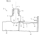
- Fig. 3 schematically shows in a side cross-section of the advantageous embodiment of a dishwasher 1 according to Fig. 1 arranged door lock 2 according to Fig. 2 in an open position of the door 30.
- the Locking bolt 3 In the open position is the Locking bolt 3 in a rest position, ie in an equilibrium of forces.
- the locking end 4 of the locking bolt 3 preferably projects into the charging opening 21 of the washing compartment 20 of the dishwasher 1, that upon closing the door 30, due to a force applied to the door closing force F G , the inner edge 34 of the inner door 32 with its operating range 34a abuts against the second, flatter operating region 3b of the closing piston 3.
- the actuation region 34a of the inner edge 34 of the inner door 32 and the second actuation region 3b of the closing piston 3 come into operative contact due to the closing force F G in such a way that an actuating force F B is generated by which the closing piston 3 counteracts the clamping force F S acting on it Direction of the elastic element 6 is linearly shifted.
- the closing force F G also overcomes the frictional force which counteracts the contact surface between the actuating region 3b of the closing piston 3 and the actuating region 34a of the inner edge 34 of the inner door 32. Characterized in that the actuating portion 3b of the locking piston 3 is formed flat, less force is required to close the door 30, as to open.
- the locking end 4 of the closing piston 3 first slides along the inner edge 34 of the inner door 32 of the door 30. After pushing back the closing piston 3 by the inner edge 34 of the inner door 32, the closing piston 3 slides along the frame 33 of the inner door 32 until it engages in the recess 5 in the frame 33 of the inner door 32 and acting on the basis of acting on him clamping force F S Closing position reached.
- the door lock is structurally very simple.
- the recess may be formed, for example, as an impression in the frame of the door or the frame of the inner door. Such a depression can be produced very easily.
- Such a door lock also allows the dishwasher, in particular a domestic dishwasher, is easy to produce.
- one or more door locksmiths can be provided on the dishwasher, in particular the domestic dishwasher.
- the closing piston of the door lock can be arranged in or on the door or the inner door of the door, in particular in the frame of the door or the inner door.
- the depression is provided in the rinsing container or the rinsing container frame element, in particular in its inner side facing the charging opening.
- the closing piston in or on the rinsing container in particular its front edge element or Spül reliereverenelement be arranged.
- the recess is then provided in the frame of the door or the inner door of the door. It is possible that both variants are provided on a dishwasher.
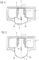
- FIG. 4 and 5 is schematically shown in each case a side cross section of a arranged in a housing 7 closing piston 3 of an advantageous embodiment of a dishwasher according to Fig. 1 shown.
- the closing piston 3 is held linearly displaceable in the linear guide 8.
- the spring-elastic element 6 exerts a clamping force F S on the closing piston 3.
- the displaceability of the closing plunger 3 may be limited by a limiting element, not shown.
- the closing piston 3 may be attached to one end of the resilient element 6.
- the resilient element 6 may be attached to the housing 7.
- the linear guide 8 is held on the inside of the housing 7.
- the Arretierende 4 of the closing piston 3 has two operating areas 3a, 3b, due to their design or form in cooperation with a mating contour of the recess 5 or the door or the Spül employers and a closing force F G or tightening force F A an operating force F B on the Transfer piston 3.
- the locking 4 of the locking piston 3 is formed angular.
- the first and the second operating region 3a, 3b are formed as flat surfaces which extend differently inclined to the longitudinal axis L of the linear guide 8.
- the locking 4 of the locking piston 3 is semicircular.
- the first and second operating portions 3a, 3b are formed as curved surfaces.
- Fig. 6 schematically shows a perspective view of the feed opening 21 of a washing container 20 and a pivotally mounted on the washing container 20 door 30 of an advantageous other embodiment of a dishwasher according to Fig. 1 .
- the housing 7 of the door lock 2 is arranged on the upper, front Spül matterserrand 26, in particular edge element or Spül employerrahmenelement, the washing container 20. It is there in particular centrally mounted.
- the housing 7 is arranged in particular such that the closing piston 3 protrudes in its rest position with its locking 4 in the vertical direction in the feed opening 21 and in the vertical direction upwards in the form of a linear lifting movement against a spring bias is gurdgurbar.
- the recess 5 of the door lock 2 is provided in the frame 31 of the door 30.
- the recess 5 of the door lock 2 is arranged in the frame 31 of the door, that in a final position, ie with the door closed 30, at least the locking 4 of the locking piston 3 due to acting on him clamping force in the recess, in particular form-fitting, can intervene ,
- the door 30 can also be arranged so as to be movable on the dishwasher 1.
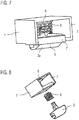
- FIGS. 7 and 8 schematically is a perspective view of a arranged in a housing 7 closing piston 3, which is acted upon by a resilient element 6 with a clamping force shown.
- the closing piston 3 and the resilient element 6 are arranged in the housing 7.
- the closing piston 3 is guided on the linear guide 8 linearly displaceable.
- Fig. 8 shows an exploded view of a part of the door lock 2 of a closing piston, a spring-elastic element and a housing for receiving the resilient element and the closing piston,
Landscapes
- Washing And Drying Of Tableware (AREA)
Priority Applications (2)
| Application Number | Priority Date | Filing Date | Title |
|---|---|---|---|
| PL10172898T PL2289386T3 (pl) | 2009-08-25 | 2010-08-16 | Zmywarka do naczyń, zwłaszcza zmywarka do naczyń gospodarstwa domowego |
| EP10172898.8A EP2289386B1 (de) | 2009-08-25 | 2010-08-16 | Geschirrspülmaschine, insbesondere Haushaltsgeschirrspülmaschine |
Applications Claiming Priority (2)
| Application Number | Priority Date | Filing Date | Title |
|---|---|---|---|
| EP09382156 | 2009-08-25 | ||
| EP10172898.8A EP2289386B1 (de) | 2009-08-25 | 2010-08-16 | Geschirrspülmaschine, insbesondere Haushaltsgeschirrspülmaschine |
Publications (2)
| Publication Number | Publication Date |
|---|---|
| EP2289386A1 EP2289386A1 (de) | 2011-03-02 |
| EP2289386B1 true EP2289386B1 (de) | 2019-10-16 |
Family
ID=43032976
Family Applications (1)
| Application Number | Title | Priority Date | Filing Date |
|---|---|---|---|
| EP10172898.8A Active EP2289386B1 (de) | 2009-08-25 | 2010-08-16 | Geschirrspülmaschine, insbesondere Haushaltsgeschirrspülmaschine |
Country Status (4)
| Country | Link |
|---|---|
| EP (1) | EP2289386B1 (pl) |
| CN (1) | CN101991395A (pl) |
| ES (1) | ES2386266A1 (pl) |
| PL (1) | PL2289386T3 (pl) |
Citations (1)
| Publication number | Priority date | Publication date | Assignee | Title |
|---|---|---|---|---|
| DE3842639A1 (de) * | 1988-12-18 | 1990-06-21 | Hobart Ag | Vorrichtung zum arretieren einer tuer |
Family Cites Families (10)
| Publication number | Priority date | Publication date | Assignee | Title |
|---|---|---|---|---|
| JP2504714B2 (ja) * | 1993-04-07 | 1996-06-05 | タキゲン製造株式会社 | 引出し回転型扉用ロックハンドル装置 |
| IT238838Y1 (it) * | 1995-02-22 | 2000-11-15 | Dihr Internat | Dispositivo di chiusura della porta di macchine lavatrici |
| DE10236777A1 (de) * | 2002-08-10 | 2004-03-04 | Ellenberger & Poensgen Gmbh | Elektrothermisch gesteuerte Verriegelungsvorrichtung für eine Gerätetür |
| KR100457580B1 (ko) * | 2002-11-28 | 2004-11-18 | 엘지전자 주식회사 | 도어 잠금 장치 |
| KR100457586B1 (ko) * | 2002-11-28 | 2004-11-17 | 엘지전자 주식회사 | 식기세척기의 도어 개폐장치 |
| US7306266B2 (en) * | 2004-03-05 | 2007-12-11 | Illinois Tool Works, Inc. | Appliance latch having a rotating latch hook mounted on a linear slide |
| ITTO20040534A1 (it) * | 2004-07-30 | 2004-10-30 | Itw Ind Components Srl | Dispositivo di incaglio per una porta di un elettrodomestico, in particolare una lavastoviglie |
| CN2737887Y (zh) * | 2004-11-05 | 2005-11-02 | 陆小强 | 锁的离合装置 |
| CN1778263A (zh) * | 2004-11-26 | 2006-05-31 | 乐金电子(天津)电器有限公司 | 洗碗机门开闭结构 |
| KR20080002784A (ko) * | 2005-04-19 | 2008-01-04 | 베에스하 보쉬 운트 지멘스 하우스게랫테 게엠베하 | 가전제품용 로크 |
-
2009
- 2009-09-28 ES ES200930748A patent/ES2386266A1/es not_active Withdrawn
-
2010
- 2010-08-16 EP EP10172898.8A patent/EP2289386B1/de active Active
- 2010-08-16 PL PL10172898T patent/PL2289386T3/pl unknown
- 2010-08-25 CN CN2010102637798A patent/CN101991395A/zh active Pending
Patent Citations (1)
| Publication number | Priority date | Publication date | Assignee | Title |
|---|---|---|---|---|
| DE3842639A1 (de) * | 1988-12-18 | 1990-06-21 | Hobart Ag | Vorrichtung zum arretieren einer tuer |
Also Published As
| Publication number | Publication date |
|---|---|
| ES2386266A1 (es) | 2012-08-14 |
| CN101991395A (zh) | 2011-03-30 |
| EP2289386A1 (de) | 2011-03-02 |
| PL2289386T3 (pl) | 2020-04-30 |
Similar Documents
| Publication | Publication Date | Title |
|---|---|---|
| EP2796650B1 (de) | Möbelscharnier | |
| EP2470056B1 (de) | Geschirrspülmaschine, insbesondere haushaltsgeschirrspülmaschine, mit einem türschloss | |
| AT511091B1 (de) | Schubladenzarge mit neigungsverstellung | |
| EP3266347B1 (de) | Antriebsvorrichtung für ein bewegbares möbelteil | |
| DE19811783C1 (de) | Abdeckbarer Behälter | |
| AT511081A4 (de) | Anordnung mit einer schublade und mit einer schubladenausziehführung | |
| EP3153064B1 (de) | Vorrichtung zur lösbaren verbindung eines in einem möbelkorpus eines möbelteils über eine führungseinheit beweglich geführten möbelauszugs mit der führungseinheit | |
| AT15239U1 (de) | Möbelscharnier | |
| WO2016177706A1 (de) | Möbelscharnier mit einem dämpfer und einer feder | |
| EP3153066B1 (de) | Vorrichtung zur lösbaren verbindung eines in einem möbelkorpus eines möbelteils über eine führungseinheit beweglich geführten möbelauszugs mit der führungseinheit | |
| AT413630B (de) | Ausziehsperreinrichtung | |
| EP2932003B1 (de) | Verfahren zum herstellen von kraftfahrzeugschlössern mit schräg angestellter sperrklinke | |
| WO2016177559A1 (de) | Moebelscharnier mit einem dämpfer | |
| DE20114654U1 (de) | Kühl- und Gefriergerät | |
| DE3446916A1 (de) | Fahrzeugdach | |
| WO2010112522A1 (de) | Einzugvorrichtung | |
| DE102012104997B4 (de) | Elektronischer Schalthebel zur Verbesserung der Bedienbarkeit eines Automatikgetriebes | |
| DE102005004098B4 (de) | Vorrichtung zur Ausgabe von Reinigungsmittel, insbesondere für eine Geschirrspülmaschine | |
| WO2009007090A4 (de) | Mitnehmervorrichtung für eine schiebetür | |
| EP2289387B1 (de) | Geschirrspülmaschine, insbesondere Haushaltsgeschirrspülmaschine | |
| EP2670452B1 (de) | Medizinisches gerät | |
| EP3356629B1 (de) | Beschlag für eine schiebetür und verfahren zur montage einer schiebetür | |
| EP3385177A1 (de) | Verpackungsmaschine mit neigbarer werkzeugschublade | |
| EP2843164B1 (de) | Beschlag für ein Schubladenmodul eines mobilen Fahrzeuges | |
| EP2045405B1 (de) | Betätigungsplatte für eine Betätigungsvorrichtung einer Spüleinrichtung |
Legal Events
| Date | Code | Title | Description |
|---|---|---|---|
| PUAI | Public reference made under article 153(3) epc to a published international application that has entered the european phase |
Free format text: ORIGINAL CODE: 0009012 |
|
| AK | Designated contracting states |
Kind code of ref document: A1 Designated state(s): AL AT BE BG CH CY CZ DE DK EE ES FI FR GB GR HR HU IE IS IT LI LT LU LV MC MK MT NL NO PL PT RO SE SI SK SM TR |
|
| AX | Request for extension of the european patent |
Extension state: BA ME RS |
|
| 17P | Request for examination filed |
Effective date: 20110902 |
|
| RAP1 | Party data changed (applicant data changed or rights of an application transferred) |
Owner name: BSH HAUSGERAETE GMBH |
|
| STAA | Information on the status of an ep patent application or granted ep patent |
Free format text: STATUS: EXAMINATION IS IN PROGRESS |
|
| 17Q | First examination report despatched |
Effective date: 20180119 |
|
| GRAP | Despatch of communication of intention to grant a patent |
Free format text: ORIGINAL CODE: EPIDOSNIGR1 |
|
| STAA | Information on the status of an ep patent application or granted ep patent |
Free format text: STATUS: GRANT OF PATENT IS INTENDED |
|
| INTG | Intention to grant announced |
Effective date: 20190719 |
|
| RIN1 | Information on inventor provided before grant (corrected) |
Inventor name: MESAROSCH, CHRISTIAN Inventor name: PASCUAL ITURBE, MARIA ITZIAR Inventor name: ASTIZ MONTOYA, CESAR Inventor name: HARTMANN, MICHAEL Inventor name: JERG, HELMUT |
|
| GRAS | Grant fee paid |
Free format text: ORIGINAL CODE: EPIDOSNIGR3 |
|
| GRAA | (expected) grant |
Free format text: ORIGINAL CODE: 0009210 |
|
| STAA | Information on the status of an ep patent application or granted ep patent |
Free format text: STATUS: THE PATENT HAS BEEN GRANTED |
|
| AK | Designated contracting states |
Kind code of ref document: B1 Designated state(s): AL AT BE BG CH CY CZ DE DK EE ES FI FR GB GR HR HU IE IS IT LI LT LU LV MC MK MT NL NO PL PT RO SE SI SK SM TR |
|
| REG | Reference to a national code |
Ref country code: GB Ref legal event code: FG4D Free format text: NOT ENGLISH |
|
| REG | Reference to a national code |
Ref country code: CH Ref legal event code: EP |
|
| REG | Reference to a national code |
Ref country code: DE Ref legal event code: R096 Ref document number: 502010016310 Country of ref document: DE |
|
| REG | Reference to a national code |
Ref country code: IE Ref legal event code: FG4D Free format text: LANGUAGE OF EP DOCUMENT: GERMAN |
|
| REG | Reference to a national code |
Ref country code: AT Ref legal event code: REF Ref document number: 1190480 Country of ref document: AT Kind code of ref document: T Effective date: 20191115 |
|
| REG | Reference to a national code |
Ref country code: NL Ref legal event code: MP Effective date: 20191016 |
|
| REG | Reference to a national code |
Ref country code: LT Ref legal event code: MG4D |
|
| PG25 | Lapsed in a contracting state [announced via postgrant information from national office to epo] |
Ref country code: PT Free format text: LAPSE BECAUSE OF FAILURE TO SUBMIT A TRANSLATION OF THE DESCRIPTION OR TO PAY THE FEE WITHIN THE PRESCRIBED TIME-LIMIT Effective date: 20200217 Ref country code: NO Free format text: LAPSE BECAUSE OF FAILURE TO SUBMIT A TRANSLATION OF THE DESCRIPTION OR TO PAY THE FEE WITHIN THE PRESCRIBED TIME-LIMIT Effective date: 20200116 Ref country code: BG Free format text: LAPSE BECAUSE OF FAILURE TO SUBMIT A TRANSLATION OF THE DESCRIPTION OR TO PAY THE FEE WITHIN THE PRESCRIBED TIME-LIMIT Effective date: 20200116 Ref country code: FI Free format text: LAPSE BECAUSE OF FAILURE TO SUBMIT A TRANSLATION OF THE DESCRIPTION OR TO PAY THE FEE WITHIN THE PRESCRIBED TIME-LIMIT Effective date: 20191016 Ref country code: LV Free format text: LAPSE BECAUSE OF FAILURE TO SUBMIT A TRANSLATION OF THE DESCRIPTION OR TO PAY THE FEE WITHIN THE PRESCRIBED TIME-LIMIT Effective date: 20191016 Ref country code: SE Free format text: LAPSE BECAUSE OF FAILURE TO SUBMIT A TRANSLATION OF THE DESCRIPTION OR TO PAY THE FEE WITHIN THE PRESCRIBED TIME-LIMIT Effective date: 20191016 Ref country code: LT Free format text: LAPSE BECAUSE OF FAILURE TO SUBMIT A TRANSLATION OF THE DESCRIPTION OR TO PAY THE FEE WITHIN THE PRESCRIBED TIME-LIMIT Effective date: 20191016 Ref country code: ES Free format text: LAPSE BECAUSE OF FAILURE TO SUBMIT A TRANSLATION OF THE DESCRIPTION OR TO PAY THE FEE WITHIN THE PRESCRIBED TIME-LIMIT Effective date: 20191016 Ref country code: NL Free format text: LAPSE BECAUSE OF FAILURE TO SUBMIT A TRANSLATION OF THE DESCRIPTION OR TO PAY THE FEE WITHIN THE PRESCRIBED TIME-LIMIT Effective date: 20191016 |
|
| PG25 | Lapsed in a contracting state [announced via postgrant information from national office to epo] |
Ref country code: HR Free format text: LAPSE BECAUSE OF FAILURE TO SUBMIT A TRANSLATION OF THE DESCRIPTION OR TO PAY THE FEE WITHIN THE PRESCRIBED TIME-LIMIT Effective date: 20191016 Ref country code: IS Free format text: LAPSE BECAUSE OF FAILURE TO SUBMIT A TRANSLATION OF THE DESCRIPTION OR TO PAY THE FEE WITHIN THE PRESCRIBED TIME-LIMIT Effective date: 20200224 |
|
| PG25 | Lapsed in a contracting state [announced via postgrant information from national office to epo] |
Ref country code: AL Free format text: LAPSE BECAUSE OF FAILURE TO SUBMIT A TRANSLATION OF THE DESCRIPTION OR TO PAY THE FEE WITHIN THE PRESCRIBED TIME-LIMIT Effective date: 20191016 |
|
| REG | Reference to a national code |
Ref country code: DE Ref legal event code: R097 Ref document number: 502010016310 Country of ref document: DE |
|
| PG2D | Information on lapse in contracting state deleted |
Ref country code: IS |
|
| PG25 | Lapsed in a contracting state [announced via postgrant information from national office to epo] |
Ref country code: DK Free format text: LAPSE BECAUSE OF FAILURE TO SUBMIT A TRANSLATION OF THE DESCRIPTION OR TO PAY THE FEE WITHIN THE PRESCRIBED TIME-LIMIT Effective date: 20191016 Ref country code: EE Free format text: LAPSE BECAUSE OF FAILURE TO SUBMIT A TRANSLATION OF THE DESCRIPTION OR TO PAY THE FEE WITHIN THE PRESCRIBED TIME-LIMIT Effective date: 20191016 Ref country code: RO Free format text: LAPSE BECAUSE OF FAILURE TO SUBMIT A TRANSLATION OF THE DESCRIPTION OR TO PAY THE FEE WITHIN THE PRESCRIBED TIME-LIMIT Effective date: 20191016 Ref country code: CZ Free format text: LAPSE BECAUSE OF FAILURE TO SUBMIT A TRANSLATION OF THE DESCRIPTION OR TO PAY THE FEE WITHIN THE PRESCRIBED TIME-LIMIT Effective date: 20191016 Ref country code: IS Free format text: LAPSE BECAUSE OF FAILURE TO SUBMIT A TRANSLATION OF THE DESCRIPTION OR TO PAY THE FEE WITHIN THE PRESCRIBED TIME-LIMIT Effective date: 20200216 |
|
| PLBE | No opposition filed within time limit |
Free format text: ORIGINAL CODE: 0009261 |
|
| STAA | Information on the status of an ep patent application or granted ep patent |
Free format text: STATUS: NO OPPOSITION FILED WITHIN TIME LIMIT |
|
| PG25 | Lapsed in a contracting state [announced via postgrant information from national office to epo] |
Ref country code: SM Free format text: LAPSE BECAUSE OF FAILURE TO SUBMIT A TRANSLATION OF THE DESCRIPTION OR TO PAY THE FEE WITHIN THE PRESCRIBED TIME-LIMIT Effective date: 20191016 Ref country code: SK Free format text: LAPSE BECAUSE OF FAILURE TO SUBMIT A TRANSLATION OF THE DESCRIPTION OR TO PAY THE FEE WITHIN THE PRESCRIBED TIME-LIMIT Effective date: 20191016 Ref country code: IT Free format text: LAPSE BECAUSE OF FAILURE TO SUBMIT A TRANSLATION OF THE DESCRIPTION OR TO PAY THE FEE WITHIN THE PRESCRIBED TIME-LIMIT Effective date: 20191016 |
|
| 26N | No opposition filed |
Effective date: 20200717 |
|
| PG25 | Lapsed in a contracting state [announced via postgrant information from national office to epo] |
Ref country code: SI Free format text: LAPSE BECAUSE OF FAILURE TO SUBMIT A TRANSLATION OF THE DESCRIPTION OR TO PAY THE FEE WITHIN THE PRESCRIBED TIME-LIMIT Effective date: 20191016 |
|
| PG25 | Lapsed in a contracting state [announced via postgrant information from national office to epo] |
Ref country code: MC Free format text: LAPSE BECAUSE OF FAILURE TO SUBMIT A TRANSLATION OF THE DESCRIPTION OR TO PAY THE FEE WITHIN THE PRESCRIBED TIME-LIMIT Effective date: 20191016 |
|
| REG | Reference to a national code |
Ref country code: CH Ref legal event code: PL |
|
| GBPC | Gb: european patent ceased through non-payment of renewal fee |
Effective date: 20200816 |
|
| PG25 | Lapsed in a contracting state [announced via postgrant information from national office to epo] |
Ref country code: LI Free format text: LAPSE BECAUSE OF NON-PAYMENT OF DUE FEES Effective date: 20200831 Ref country code: CH Free format text: LAPSE BECAUSE OF NON-PAYMENT OF DUE FEES Effective date: 20200831 Ref country code: LU Free format text: LAPSE BECAUSE OF NON-PAYMENT OF DUE FEES Effective date: 20200816 |
|
| REG | Reference to a national code |
Ref country code: BE Ref legal event code: MM Effective date: 20200831 |
|
| PG25 | Lapsed in a contracting state [announced via postgrant information from national office to epo] |
Ref country code: FR Free format text: LAPSE BECAUSE OF NON-PAYMENT OF DUE FEES Effective date: 20200831 |
|
| PG25 | Lapsed in a contracting state [announced via postgrant information from national office to epo] |
Ref country code: BE Free format text: LAPSE BECAUSE OF NON-PAYMENT OF DUE FEES Effective date: 20200831 Ref country code: GB Free format text: LAPSE BECAUSE OF NON-PAYMENT OF DUE FEES Effective date: 20200816 Ref country code: IE Free format text: LAPSE BECAUSE OF NON-PAYMENT OF DUE FEES Effective date: 20200816 |
|
| REG | Reference to a national code |
Ref country code: AT Ref legal event code: MM01 Ref document number: 1190480 Country of ref document: AT Kind code of ref document: T Effective date: 20200816 |
|
| PG25 | Lapsed in a contracting state [announced via postgrant information from national office to epo] |
Ref country code: AT Free format text: LAPSE BECAUSE OF NON-PAYMENT OF DUE FEES Effective date: 20200816 |
|
| PG25 | Lapsed in a contracting state [announced via postgrant information from national office to epo] |
Ref country code: MT Free format text: LAPSE BECAUSE OF FAILURE TO SUBMIT A TRANSLATION OF THE DESCRIPTION OR TO PAY THE FEE WITHIN THE PRESCRIBED TIME-LIMIT Effective date: 20191016 Ref country code: CY Free format text: LAPSE BECAUSE OF FAILURE TO SUBMIT A TRANSLATION OF THE DESCRIPTION OR TO PAY THE FEE WITHIN THE PRESCRIBED TIME-LIMIT Effective date: 20191016 |
|
| PG25 | Lapsed in a contracting state [announced via postgrant information from national office to epo] |
Ref country code: MK Free format text: LAPSE BECAUSE OF FAILURE TO SUBMIT A TRANSLATION OF THE DESCRIPTION OR TO PAY THE FEE WITHIN THE PRESCRIBED TIME-LIMIT Effective date: 20191016 |
|
| PG25 | Lapsed in a contracting state [announced via postgrant information from national office to epo] |
Ref country code: GR Free format text: LAPSE BECAUSE OF FAILURE TO SUBMIT A TRANSLATION OF THE DESCRIPTION OR TO PAY THE FEE WITHIN THE PRESCRIBED TIME-LIMIT Effective date: 20191016 |
|
| PGFP | Annual fee paid to national office [announced via postgrant information from national office to epo] |
Ref country code: DE Payment date: 20250831 Year of fee payment: 16 |
|
| PGFP | Annual fee paid to national office [announced via postgrant information from national office to epo] |
Ref country code: TR Payment date: 20250808 Year of fee payment: 16 Ref country code: PL Payment date: 20250801 Year of fee payment: 16 |