EP2288910B1 - Sonde zur überprüfung der oberfläche einer in einer scheibe eines strahltriebwerks umlaufenden nut mittels wirbelströmen - Google Patents
Sonde zur überprüfung der oberfläche einer in einer scheibe eines strahltriebwerks umlaufenden nut mittels wirbelströmen Download PDFInfo
- Publication number
- EP2288910B1 EP2288910B1 EP09757727.4A EP09757727A EP2288910B1 EP 2288910 B1 EP2288910 B1 EP 2288910B1 EP 09757727 A EP09757727 A EP 09757727A EP 2288910 B1 EP2288910 B1 EP 2288910B1
- Authority
- EP
- European Patent Office
- Prior art keywords
- probe
- sensors
- slot
- stem
- inspection
- Prior art date
- Legal status (The legal status is an assumption and is not a legal conclusion. Google has not performed a legal analysis and makes no representation as to the accuracy of the status listed.)
- Active
Links
Images

Classifications
-
- G—PHYSICS
- G01—MEASURING; TESTING
- G01N—INVESTIGATING OR ANALYSING MATERIALS BY DETERMINING THEIR CHEMICAL OR PHYSICAL PROPERTIES
- G01N27/00—Investigating or analysing materials by the use of electric, electrochemical, or magnetic means
- G01N27/72—Investigating or analysing materials by the use of electric, electrochemical, or magnetic means by investigating magnetic variables
- G01N27/82—Investigating or analysing materials by the use of electric, electrochemical, or magnetic means by investigating magnetic variables for investigating the presence of flaws
- G01N27/90—Investigating or analysing materials by the use of electric, electrochemical, or magnetic means by investigating magnetic variables for investigating the presence of flaws using eddy currents
- G01N27/904—Investigating or analysing materials by the use of electric, electrochemical, or magnetic means by investigating magnetic variables for investigating the presence of flaws using eddy currents with two or more sensors
-
- G—PHYSICS
- G01—MEASURING; TESTING
- G01N—INVESTIGATING OR ANALYSING MATERIALS BY DETERMINING THEIR CHEMICAL OR PHYSICAL PROPERTIES
- G01N27/00—Investigating or analysing materials by the use of electric, electrochemical, or magnetic means
- G01N27/72—Investigating or analysing materials by the use of electric, electrochemical, or magnetic means by investigating magnetic variables
- G01N27/82—Investigating or analysing materials by the use of electric, electrochemical, or magnetic means by investigating magnetic variables for investigating the presence of flaws
- G01N27/90—Investigating or analysing materials by the use of electric, electrochemical, or magnetic means by investigating magnetic variables for investigating the presence of flaws using eddy currents
- G01N27/9006—Details, e.g. in the structure or functioning of sensors
Definitions
- the present invention relates to a probe for eddy current monitoring of surface irregularities and irregularities of a circumferential cavity of a turbojet disk.
- lateral faces concave annular-shaped faces
- This type of cells therefore requires a very regular control.
- eddy current control is commonly used for the verification of their surface condition.
- This type of control consists in scanning the surface to be examined using a probe equipped with a sensor, which, by creating an electromagnetic field, produces eddy currents in the part to be controlled. In practice, the piece is most often rotated while the probe remains in place on its support.
- the flow of eddy currents is altered, and the sensor generates an electrical signal corresponding to this alteration.
- the amplitude of this signal is proportional to the importance of the detected surface anomaly. For this proportionality to be respected, however, the contact between the surface to be tested and the eddy current probe must be maintained permanently.
- Hoof probes composed of a single-element sensor fixed at the end of a rod that can be displaced via its support in the axial and radial directions of the turbojet disk are already known.
- This type of probe requires a stepwise displacement of the probe along the profile to be examined, each displacement of the probe in the axial direction being followed by a rotation of the disk or the probe, in order to scan the whole of the surface of the cell.
- the single-element sensor is introduced into the cell, brought into contact with the surface to be controlled, then the part undergoes a complete revolution so that a complete circumferential band of the cell is examined. This operation is repeated several times by changing the position each time from the single-element sensor to the surface to be inspected, until the entire surface of the cell is scanned.
- the single-element sensor being asymmetrical, after controlling a side face of the cell, it is necessary to turn it to examine the opposite side.
- the result to evaluate the surface condition of the cell is obtained by incrementing the results of the various measurements made using the single-element sensor.
- the present invention relates in particular to an improvement of a multi-element sensor.
- the invention proposes to limit the number of operations necessary for the eddy current control of the surface of the circumferential cells of the turbojet disk. It also aims to allow optimum positioning of the probe in the cell. It thus makes it possible to considerably reduce the duration of the control and to increase the precision of the results.
- the invention relates to a probe for eddy current monitoring of the surface of a circumferential cavity formed in a turbojet disk, as defined in claim 3.
- Each multielement sensor is respectively intended to come into contact with a lateral face of the cell.
- These multielement sensors comprise a plurality of elements delivering high frequency signals corresponding to the level of deterioration of the controlled surface. The acquisition of these signals is performed in real time, a digital generator of eddy currents ensuring their transmission, reception and demodulation. These signals are then transformed into images by a processing software, so that they can be interpreted by the operator.
- the set of two multi-element sensors positioned back-to-back has a width necessarily greater than the input width of the cell.
- the rod is pivotally mounted on its support, for example by a system of ball slide and springs.
- At least one spring is interposed between the two multi-element sensors.
- each multi-element sensor has a shape corresponding to the profile of a face of the cell to be controlled.
- the two multi-element sensors are held back-to-back and are connected to the rod by a sliding arrangement.
- step d) of the method described above the probe remains fixed and the disc rotates at an angle of 360 °
- the probe according to the invention decreases the influence of the human factor on the measurement results and thus limits the risks of error.
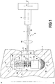
- the figure 1 represents a disk portion 1 of a turbojet, in which has been machined a circumferential cavity 2 for welcome a series of blades.
- the cell consists of a substantially cylindrical central face 4 of axis AA, and two lateral faces 3 of concave annular shape.
- the cell 2 opens by an annular opening 5 of width L 1 taken in the axial direction.
- the width L 1 of the opening 5 is smaller than the largest width L 2 of the cell 2 taken in the axial direction, that is to say between the lateral faces 3.
- the probe 6 consists of a rod 7, a support 8 and two multielement sensors 9.
- the arrows f 1 , f 2 , f 3 represent the degrees of freedom of the rod 7, provided by ball rails and springs not shown. These degrees of freedom are defined below with reference to the mark of the turbojet disk.
- the arrow f 1 corresponds to an axial displacement of the rod
- the arrow f 2 corresponds to a radial displacement
- f 3 denotes a pivoting of the rod about its axis yy 'extending in the radial direction of the rod. disk 1.
- Each sensor 9 consists of a contact portion 10 and a fastening portion 11.
- the contact portion 10 has a profile substantially corresponding to the profile of the side face 3 intended to be scanned. As illustrated on the figure 1 , the contact portion 10 has a plurality of elements 12 delivering high frequency signals corresponding to the level of alteration of the surface with which they come into contact.
- the attachment portion 11 is intended to accommodate the mounting means of the sensor 9 relative to the rod 7.
- the sensors 9 are connected to the rod 7 by means of two return springs 13.
- a sliding guide 14 is furthermore provided for holding the two sensors 9 back-to-back and in a plane perpendicular to the 'axis yy' of the rod 7.
- This guide 14 consists of two rods sliding in a bore 15 formed in the attachment portion 11 of a corresponding sensor 9, the bores 15 of the two sensors 9 being arranged facing the one of the other.
- the figure 2a represents the turbojet disk 1, in which is formed the cell 2 which is desired to control the surface condition.
- the probe 6 is moved in the direction f 1 until its axis is located in the median plane of the circumferential cavity 2.
- the probe is then rotated along f 3 so that the two sensors 9 arranged back-to-back back are both placed opposite the opening of the cell 2, their common axis xx 'being perpendicular to the axis AA of the disk.
- the two sensors 9 of the probe 6 are then inserted into the cell 2 by a displacement of the rod 7 in the radial direction f 2 .
- the Figure 2c represents the positioning of the sensors 9 against the lateral faces 3 of the cell 2.
- the rod 7 is rotated by an angle of 90 ° about its axis y-y ', so that the common axis of the two sensors xx 'is parallel to the axis AA of the turbojet disk 1.
- the sensors 9 come into abutment against the lateral faces 3 of the cell 2 before being correctly positioned in the AA axis of the disc 1.
- the return springs 13 are compressed, forcing the contact of the sensors 9 against the side faces 3 of the cell 2.
- the spring of reminder contributes to the maintenance of an optimal contact between the sensors 9 and the surface 3 of the cell 2, and, consequently, to obtain an electrical signal precisely proportional to the level of deterioration of the surface.
- the arrow B shown on the Figure 2c illustrates the scanning operation of the cell 2.
- the probe 6 remains in place, while the turbojet disk 1 rotates about its axis AA.
- the two sensors 9 deliver high frequency signals proportional to the level of alteration of the side faces 3 of the cell 2. These signals are then filtered and displayed on screen in the form of representative images results obtained, exploitable by an operator.
Landscapes
- Chemical & Material Sciences (AREA)
- General Health & Medical Sciences (AREA)
- Life Sciences & Earth Sciences (AREA)
- General Physics & Mathematics (AREA)
- Health & Medical Sciences (AREA)
- Immunology (AREA)
- Analytical Chemistry (AREA)
- Biochemistry (AREA)
- Pathology (AREA)
- Physics & Mathematics (AREA)
- Electrochemistry (AREA)
- Chemical Kinetics & Catalysis (AREA)
- Investigating Or Analyzing Materials By The Use Of Magnetic Means (AREA)
- Measurement Of Length, Angles, Or The Like Using Electric Or Magnetic Means (AREA)
- Length Measuring Devices With Unspecified Measuring Means (AREA)
- Testing Of Devices, Machine Parts, Or Other Structures Thereof (AREA)
- Structures Of Non-Positive Displacement Pumps (AREA)
- Testing Of Engines (AREA)
Claims (6)
- Verfahren zur Überprüfung einer in einer Scheibe (1) eines Strahltriebwerks gebildeten umlaufenden Nut mittels Wirbelströmen unter Verwendung einer Sonde (6), wobei die Sonde einen Schaft (7), der an einem Träger (8) befestigt ist, einen ersten Mehrfachelement-Sensor (9) und einen zweiten Mehrfachelement-Sensor (9) zur Durchführung der Überprüfung aufweist, die mit den Bewegungen des Schafts (7) verbunden und geeignet sind, in die umlaufende Nut (2) eingeführt zu werden, wobei die beiden Mehrfachelement-Sensoren (9) Rücken-an-Rücken angeordnet und gegenläufig derart elastisch vorgespannt sind, dass ein optimaler Kontakt dieser Mehrfachelement-Sensoren (9) mit den zu überprüfenden gegenüberliegenden Flächen (3) gewährleistet wird, wobei der Schaft (7) schwenkbar um seine Achse (y-y') gelagert ist, um die beiden Mehrfachelement-Sensoren (9) in die Nut (2) einzuführen, wobei das Verfahren dadurch gekennzeichnet ist, dass es die Schritte umfasst, die bestehen aus:a) Positionieren der beiden Sensoren (9) gegenüber der Öffnung (5) der Nut derart, dass eine gemeinsame Achse (x-x') von diesen senkrecht zur Achse (A-A) der Scheibe (1) steht,b) Verlagern der Sonde (6) in einer radialen Richtung (f2) der Scheibe zur Innenseite der Nut (2) gerichtet, um die beiden Mehrfachelement-Sensoren (9) in die Nut (2) einzuführen, und dannc) Schwenken des Schafts (7) um 90°derart, dass die Mehrfachelement-Sensoren (9) mit den zu überprüfenden Seitenflächen (3) der Nut (2) in Berührung kommen, und schließlichd) Abtasten der gesamten Oberfläche der umlaufenden Nut (2).
- Verfahren nach Anspruch 2, dadurch gekennzeichnet, dass während des Schritts d) die Sonde (6) fixiert bleibt und die Scheibe (1) um einen Winkel von 360° dreht.
- Wirbelstromsonde (6) zur Überprüfung der Oberfläche einer umlaufenden Nut (2), die in einer Scheibe (1) eines Strahltriebwerks ausgebildet ist, umfassend einen Schaft (7), der an einem Träger (8) befestigt ist, einen ersten Mehrfachelement-Sensor (9) und einen zweiten Mehrfachelement-Sensor (9) zur Durchführung der Überprüfung, die mit den Bewegungen des Schafts (7) verbunden und geeignet sind, in die umlaufende Nut (2) eingeführt zu werden, wobei die beiden Mehrfachelement-Sensoren (9) Rücken-an-Rücken angeordnet und gegenläufig derart elastisch vorgespannt sind, dass ein optimaler Kontakt dieser Mehrfachelement-Sensoren (9) mit den zu überprüfenden gegenüberliegenden Flächen (3) gewährleistet wird, wobei der Schaft (7) schwenkbar um seine Achse (y-y') gelagert ist, um die beiden Mehrfachelement-Sensoren (9) in die Nut (2) einzuführen, wobei die Sonde (6) dadurch gekennzeichnet ist, dass sie zur Umsetzung des Verfahrens nach Anspruch 1 geeignet ist.
- Sonde nach Anspruch 3, dadurch gekennzeichnet, dass zwischen den beiden Mehrfachelement-Sensoren (9) mindestens eine Feder (13) eingefügt ist.
- Sonde nach einem der Ansprüche 3 bis 4, dadurch gekennzeichnet, dass jeder Mehrfachelement-Sensor (9) eine dem Profil einer zu überprüfenden Seite (3) der Nut (2) entsprechende Form aufweist.
- Sonde nach einem der Ansprüche 3 bis 5, dadurch gekennzeichnet, dass die beiden Mehrfachelement-Sensoren (9) Rücken-an-Rücken gehalten werden und durch eine Gleitanordnung (14) mit dem Schaft (7) verbunden sind.
Applications Claiming Priority (2)
| Application Number | Priority Date | Filing Date | Title |
|---|---|---|---|
| FR0853109A FR2931242B1 (fr) | 2008-05-14 | 2008-05-14 | Sonde destinee au controle par courants de foucault de la surface d'une alveole circonferentielle d'un disque de turboreacteur |
| PCT/FR2009/050877 WO2009147351A2 (fr) | 2008-05-14 | 2009-05-13 | Sonde destinee au controle par courants de foucault de la surface d'une alveole circonferentielle d'un disque de turboreacteur |
Publications (2)
| Publication Number | Publication Date |
|---|---|
| EP2288910A2 EP2288910A2 (de) | 2011-03-02 |
| EP2288910B1 true EP2288910B1 (de) | 2018-01-10 |
Family
ID=40039759
Family Applications (1)
| Application Number | Title | Priority Date | Filing Date |
|---|---|---|---|
| EP09757727.4A Active EP2288910B1 (de) | 2008-05-14 | 2009-05-13 | Sonde zur überprüfung der oberfläche einer in einer scheibe eines strahltriebwerks umlaufenden nut mittels wirbelströmen |
Country Status (9)
| Country | Link |
|---|---|
| US (1) | US8866471B2 (de) |
| EP (1) | EP2288910B1 (de) |
| JP (1) | JP5562942B2 (de) |
| CN (1) | CN102027363B (de) |
| BR (1) | BRPI0912627B1 (de) |
| CA (1) | CA2725797C (de) |
| FR (1) | FR2931242B1 (de) |
| RU (1) | RU2494387C2 (de) |
| WO (1) | WO2009147351A2 (de) |
Families Citing this family (5)
| Publication number | Priority date | Publication date | Assignee | Title |
|---|---|---|---|---|
| US9110036B2 (en) * | 2012-08-02 | 2015-08-18 | Olympus Ndt, Inc. | Assembly with a universal manipulator for inspecting dovetail of different sizes |
| JP6121711B2 (ja) * | 2012-12-28 | 2017-04-26 | 三菱日立パワーシステムズ株式会社 | 渦電流探傷装置および渦電流探傷方法 |
| CN104181227B (zh) * | 2013-05-21 | 2017-02-08 | 核动力运行研究所 | 一种外穿式弹性线圈涡流探头 |
| US9484209B1 (en) | 2015-11-20 | 2016-11-01 | International Business Machines Corporation | Flexible and stretchable sensors formed by patterned spalling |
| CN107991382B (zh) * | 2017-10-16 | 2024-04-05 | 中广核检测技术有限公司 | 一种涡流检查装置 |
Citations (1)
| Publication number | Priority date | Publication date | Assignee | Title |
|---|---|---|---|---|
| US20070120559A1 (en) * | 2005-11-30 | 2007-05-31 | Yuri Plotnikov | Pulsed eddy current pipeline inspection system and method |
Family Cites Families (15)
| Publication number | Priority date | Publication date | Assignee | Title |
|---|---|---|---|---|
| DE2530816C3 (de) | 1975-07-10 | 1980-07-31 | Institut Dr. Friedrich Foerster Pruefgeraetebau, 7410 Reutlingen | Wirbelstromprüfgerät zum Abtasten der Oberfläche eines Prüfteils |
| JPH0577760U (ja) * | 1991-05-28 | 1993-10-22 | 原子燃料工業株式会社 | 金属細管の検査装置 |
| US5315234A (en) * | 1992-04-03 | 1994-05-24 | General Electric Company | Eddy current device for inspecting a component having a flexible support with a plural sensor array |
| US5442286A (en) * | 1993-09-22 | 1995-08-15 | General Electric Company | Eddy current array inspection device |
| US5781007A (en) * | 1995-10-24 | 1998-07-14 | General Electric Company | Portable three axis scanner to inspect a gas turbine engine spool by eddy current or ultrasonic inspection |
| IL126315A0 (en) * | 1997-09-25 | 1999-05-09 | Siemens Power Corp | Turbine blade inspection apparatus |
| US6152698A (en) * | 1999-08-02 | 2000-11-28 | General Electric Company | Kit of articles and method for assembling articles along a holder distance |
| US6545467B1 (en) * | 2000-10-27 | 2003-04-08 | General Electric Company | Contoured surface eddy current inspection system |
| US6469503B2 (en) * | 2001-03-26 | 2002-10-22 | General Electric Company | Eddy current inspection probe and method of use |
| US6972561B2 (en) * | 2003-02-28 | 2005-12-06 | General Electric Company | Internal eddy current inspection |
| US7466126B2 (en) * | 2004-07-12 | 2008-12-16 | General Electric Company | Universal sensor probe with adjustable members configured to fit between a plurality of slot openings of varying widths |
| US7518359B2 (en) * | 2005-03-09 | 2009-04-14 | General Electric Company | Inspection of non-planar parts using multifrequency eddy current with phase analysis |
| FR2915581B1 (fr) * | 2007-04-27 | 2010-09-03 | Snecma | Dispositif de controle par courants de foucault d'une cavite rectiligne |
| FR2916851B1 (fr) * | 2007-05-29 | 2010-08-13 | Snecma | Dispositif de controle non destructif, par courants de foucault d'un trou pratique dans une piece conductrice |
| FR2921158B1 (fr) * | 2007-09-19 | 2011-05-06 | Snecma | Dispositif de controle des alveoles tangentielles d'un disque de rotor |
-
2008
- 2008-05-14 FR FR0853109A patent/FR2931242B1/fr active Active
-
2009
- 2009-05-13 EP EP09757727.4A patent/EP2288910B1/de active Active
- 2009-05-13 JP JP2011508983A patent/JP5562942B2/ja active Active
- 2009-05-13 CN CN200980116932XA patent/CN102027363B/zh active Active
- 2009-05-13 BR BRPI0912627-9A patent/BRPI0912627B1/pt active IP Right Grant
- 2009-05-13 US US12/992,514 patent/US8866471B2/en active Active
- 2009-05-13 WO PCT/FR2009/050877 patent/WO2009147351A2/fr active Application Filing
- 2009-05-13 RU RU2010150900/28A patent/RU2494387C2/ru active
- 2009-05-13 CA CA2725797A patent/CA2725797C/fr active Active
Patent Citations (1)
| Publication number | Priority date | Publication date | Assignee | Title |
|---|---|---|---|---|
| US20070120559A1 (en) * | 2005-11-30 | 2007-05-31 | Yuri Plotnikov | Pulsed eddy current pipeline inspection system and method |
Also Published As
| Publication number | Publication date |
|---|---|
| WO2009147351A3 (fr) | 2010-03-11 |
| US8866471B2 (en) | 2014-10-21 |
| CA2725797A1 (fr) | 2009-12-10 |
| RU2494387C2 (ru) | 2013-09-27 |
| FR2931242A1 (fr) | 2009-11-20 |
| BRPI0912627A2 (pt) | 2016-01-26 |
| EP2288910A2 (de) | 2011-03-02 |
| WO2009147351A2 (fr) | 2009-12-10 |
| FR2931242B1 (fr) | 2010-06-11 |
| JP2011521219A (ja) | 2011-07-21 |
| US20110062954A1 (en) | 2011-03-17 |
| CN102027363B (zh) | 2012-09-26 |
| CA2725797C (fr) | 2016-03-08 |
| BRPI0912627B1 (pt) | 2019-06-25 |
| JP5562942B2 (ja) | 2014-07-30 |
| CN102027363A (zh) | 2011-04-20 |
| RU2010150900A (ru) | 2012-06-20 |
Similar Documents
| Publication | Publication Date | Title |
|---|---|---|
| EP2288910B1 (de) | Sonde zur überprüfung der oberfläche einer in einer scheibe eines strahltriebwerks umlaufenden nut mittels wirbelströmen | |
| EP1733181B1 (de) | Gemischer optischer und mechanischer sensor und dazugehöriges rücksetzverfahren | |
| CA2639589C (fr) | Dispositif de controle des alveoles tangentielles d'un disque de rotor | |
| WO2011148094A1 (fr) | Dispositif d'acquisition/distribution multipoints de fluide, en particulier sonde de prise de pression dans une entrée d'air de turbomachine | |
| EP1605259A1 (de) | Einrichtung zur zerstörungsfreien Kontrolle eines Werkstücks. | |
| EP1986003B1 (de) | Verfahren und Anlage zur nicht-destruktiven Kontrolle mit Hilfe von Wirbelströmen mit automatischer Eichung | |
| CA2396038C (fr) | Dispositif de positionnement angulaire d'une sonde d'incidence a girouette sur une paroi d'aeronef | |
| CA2629799C (fr) | Dispositif de controle par courants de foucault d'une cavite rectiligne | |
| EP3301428A1 (de) | Messkamm zum messen der parameter von austretenden gasen aus einem kanal einer strömungsmaschine | |
| WO2009103702A2 (fr) | Dispositif et procede pour la determination d'au moins une grandeur associee au rayonnement electromagnetique d'un objet sous test | |
| CA2122067C (fr) | Procede et dispositif d'etalonnage pour un ensemble de mesure du profil transversal d'epaisseur d'un produit plat | |
| FR2730058A1 (fr) | Procede de controle non destructif d'une surface, en particulier en milieu hostile | |
| WO2010037869A1 (fr) | Perfectionnements à la détection de dépôts comportant au moins un matériau ferromagnétique sur ou à proximité de la paroi externe d'un tube | |
| EP1998173B1 (de) | Nicht-destruktive Kontrollvorrichtung durch Wirbelströme eines in einem leitenden Werkstück ausgeführten Lochs | |
| EP2795302B1 (de) | Verfahren zur herstellung eines überwachungskopfes eines zerstörungsfreien überwachungssensors auf der basis von wirbelströmen | |
| EP2440817B1 (de) | Zerstörungsfreier test eines dichtungselements | |
| FR3116902A1 (fr) | Procede pour detecter d’eventuels enfoncements sur une surface apte a reflechir la lumiere | |
| FR2777817A1 (fr) | Procede et appareil de palpage de montures de lunettes, et machine de meulage correspondante | |
| FR2878951A1 (fr) | Procede et dispositif de centrage d'un rotor dans son stator au sein d'une turbine de production industrielle d'electricite | |
| EP3580555B1 (de) | Rohrinspektionseinheit mit wirbelstromsonde und entsprechendes verfahren | |
| WO2011036193A1 (fr) | Perfectionnements à la détection de dépôts comportant au moins un matériau ferromagnétique sur ou à proximité de la paroi externe d'un tube | |
| FR2949262A1 (fr) | Dispositif d'etalonnage de moyens de controle non destructif d'une piece de turbomachine | |
| EP0928409A1 (de) | Vorrichtung zum prüfen der lage von punkten eines werkstücks, insbesondere der lage von lochzentren in einer blechplatte | |
| FR2871568A1 (fr) | Installation de controle non destructif d'un rotor | |
| FR2956877A1 (fr) | Dispositif de mesure de la section de passage entre deux aubes adjacentes. |
Legal Events
| Date | Code | Title | Description |
|---|---|---|---|
| PUAI | Public reference made under article 153(3) epc to a published international application that has entered the european phase |
Free format text: ORIGINAL CODE: 0009012 |
|
| 17P | Request for examination filed |
Effective date: 20101210 |
|
| AK | Designated contracting states |
Kind code of ref document: A2 Designated state(s): AT BE BG CH CY CZ DE DK EE ES FI FR GB GR HR HU IE IS IT LI LT LU LV MC MK MT NL NO PL PT RO SE SI SK TR |
|
| AX | Request for extension of the european patent |
Extension state: AL BA RS |
|
| DAX | Request for extension of the european patent (deleted) | ||
| 17Q | First examination report despatched |
Effective date: 20170124 |
|
| GRAP | Despatch of communication of intention to grant a patent |
Free format text: ORIGINAL CODE: EPIDOSNIGR1 |
|
| INTG | Intention to grant announced |
Effective date: 20170704 |
|
| GRAS | Grant fee paid |
Free format text: ORIGINAL CODE: EPIDOSNIGR3 |
|
| GRAA | (expected) grant |
Free format text: ORIGINAL CODE: 0009210 |
|
| AK | Designated contracting states |
Kind code of ref document: B1 Designated state(s): AT BE BG CH CY CZ DE DK EE ES FI FR GB GR HR HU IE IS IT LI LT LU LV MC MK MT NL NO PL PT RO SE SI SK TR |
|
| REG | Reference to a national code |
Ref country code: GB Ref legal event code: FG4D Free format text: NOT ENGLISH |
|
| REG | Reference to a national code |
Ref country code: CH Ref legal event code: EP Ref country code: AT Ref legal event code: REF Ref document number: 962955 Country of ref document: AT Kind code of ref document: T Effective date: 20180115 |
|
| REG | Reference to a national code |
Ref country code: IE Ref legal event code: FG4D Free format text: LANGUAGE OF EP DOCUMENT: FRENCH |
|
| REG | Reference to a national code |
Ref country code: DE Ref legal event code: R096 Ref document number: 602009050338 Country of ref document: DE |
|
| REG | Reference to a national code |
Ref country code: SE Ref legal event code: TRGR |
|
| REG | Reference to a national code |
Ref country code: FR Ref legal event code: PLFP Year of fee payment: 10 |
|
| REG | Reference to a national code |
Ref country code: NL Ref legal event code: MP Effective date: 20180110 |
|
| REG | Reference to a national code |
Ref country code: AT Ref legal event code: MK05 Ref document number: 962955 Country of ref document: AT Kind code of ref document: T Effective date: 20180110 Ref country code: CH Ref legal event code: PFA Owner name: SAFRAN AIRCRAFT ENGINES, FR Free format text: FORMER OWNER: SNECMA, FR |
|
| PG25 | Lapsed in a contracting state [announced via postgrant information from national office to epo] |
Ref country code: NL Free format text: LAPSE BECAUSE OF FAILURE TO SUBMIT A TRANSLATION OF THE DESCRIPTION OR TO PAY THE FEE WITHIN THE PRESCRIBED TIME-LIMIT Effective date: 20180110 |
|
| RAP2 | Party data changed (patent owner data changed or rights of a patent transferred) |
Owner name: SAFRAN AIRCRAFT ENGINES |
|
| PG25 | Lapsed in a contracting state [announced via postgrant information from national office to epo] |
Ref country code: ES Free format text: LAPSE BECAUSE OF FAILURE TO SUBMIT A TRANSLATION OF THE DESCRIPTION OR TO PAY THE FEE WITHIN THE PRESCRIBED TIME-LIMIT Effective date: 20180110 Ref country code: CY Free format text: LAPSE BECAUSE OF FAILURE TO SUBMIT A TRANSLATION OF THE DESCRIPTION OR TO PAY THE FEE WITHIN THE PRESCRIBED TIME-LIMIT Effective date: 20180110 Ref country code: FI Free format text: LAPSE BECAUSE OF FAILURE TO SUBMIT A TRANSLATION OF THE DESCRIPTION OR TO PAY THE FEE WITHIN THE PRESCRIBED TIME-LIMIT Effective date: 20180110 Ref country code: LT Free format text: LAPSE BECAUSE OF FAILURE TO SUBMIT A TRANSLATION OF THE DESCRIPTION OR TO PAY THE FEE WITHIN THE PRESCRIBED TIME-LIMIT Effective date: 20180110 Ref country code: HR Free format text: LAPSE BECAUSE OF FAILURE TO SUBMIT A TRANSLATION OF THE DESCRIPTION OR TO PAY THE FEE WITHIN THE PRESCRIBED TIME-LIMIT Effective date: 20180110 Ref country code: NO Free format text: LAPSE BECAUSE OF FAILURE TO SUBMIT A TRANSLATION OF THE DESCRIPTION OR TO PAY THE FEE WITHIN THE PRESCRIBED TIME-LIMIT Effective date: 20180410 |
|
| PG25 | Lapsed in a contracting state [announced via postgrant information from national office to epo] |
Ref country code: BG Free format text: LAPSE BECAUSE OF FAILURE TO SUBMIT A TRANSLATION OF THE DESCRIPTION OR TO PAY THE FEE WITHIN THE PRESCRIBED TIME-LIMIT Effective date: 20180410 Ref country code: AT Free format text: LAPSE BECAUSE OF FAILURE TO SUBMIT A TRANSLATION OF THE DESCRIPTION OR TO PAY THE FEE WITHIN THE PRESCRIBED TIME-LIMIT Effective date: 20180110 Ref country code: PL Free format text: LAPSE BECAUSE OF FAILURE TO SUBMIT A TRANSLATION OF THE DESCRIPTION OR TO PAY THE FEE WITHIN THE PRESCRIBED TIME-LIMIT Effective date: 20180110 Ref country code: IS Free format text: LAPSE BECAUSE OF FAILURE TO SUBMIT A TRANSLATION OF THE DESCRIPTION OR TO PAY THE FEE WITHIN THE PRESCRIBED TIME-LIMIT Effective date: 20180510 Ref country code: GR Free format text: LAPSE BECAUSE OF FAILURE TO SUBMIT A TRANSLATION OF THE DESCRIPTION OR TO PAY THE FEE WITHIN THE PRESCRIBED TIME-LIMIT Effective date: 20180411 Ref country code: LV Free format text: LAPSE BECAUSE OF FAILURE TO SUBMIT A TRANSLATION OF THE DESCRIPTION OR TO PAY THE FEE WITHIN THE PRESCRIBED TIME-LIMIT Effective date: 20180110 |
|
| PG25 | Lapsed in a contracting state [announced via postgrant information from national office to epo] |
Ref country code: MT Free format text: LAPSE BECAUSE OF FAILURE TO SUBMIT A TRANSLATION OF THE DESCRIPTION OR TO PAY THE FEE WITHIN THE PRESCRIBED TIME-LIMIT Effective date: 20180110 |
|
| REG | Reference to a national code |
Ref country code: DE Ref legal event code: R097 Ref document number: 602009050338 Country of ref document: DE |
|
| PG25 | Lapsed in a contracting state [announced via postgrant information from national office to epo] |
Ref country code: RO Free format text: LAPSE BECAUSE OF FAILURE TO SUBMIT A TRANSLATION OF THE DESCRIPTION OR TO PAY THE FEE WITHIN THE PRESCRIBED TIME-LIMIT Effective date: 20180110 Ref country code: EE Free format text: LAPSE BECAUSE OF FAILURE TO SUBMIT A TRANSLATION OF THE DESCRIPTION OR TO PAY THE FEE WITHIN THE PRESCRIBED TIME-LIMIT Effective date: 20180110 |
|
| PLBE | No opposition filed within time limit |
Free format text: ORIGINAL CODE: 0009261 |
|
| STAA | Information on the status of an ep patent application or granted ep patent |
Free format text: STATUS: NO OPPOSITION FILED WITHIN TIME LIMIT |
|
| PG25 | Lapsed in a contracting state [announced via postgrant information from national office to epo] |
Ref country code: DK Free format text: LAPSE BECAUSE OF FAILURE TO SUBMIT A TRANSLATION OF THE DESCRIPTION OR TO PAY THE FEE WITHIN THE PRESCRIBED TIME-LIMIT Effective date: 20180110 Ref country code: CZ Free format text: LAPSE BECAUSE OF FAILURE TO SUBMIT A TRANSLATION OF THE DESCRIPTION OR TO PAY THE FEE WITHIN THE PRESCRIBED TIME-LIMIT Effective date: 20180110 Ref country code: SK Free format text: LAPSE BECAUSE OF FAILURE TO SUBMIT A TRANSLATION OF THE DESCRIPTION OR TO PAY THE FEE WITHIN THE PRESCRIBED TIME-LIMIT Effective date: 20180110 |
|
| REG | Reference to a national code |
Ref country code: CH Ref legal event code: PL |
|
| 26N | No opposition filed |
Effective date: 20181011 |
|
| REG | Reference to a national code |
Ref country code: BE Ref legal event code: MM Effective date: 20180531 |
|
| PG25 | Lapsed in a contracting state [announced via postgrant information from national office to epo] |
Ref country code: MC Free format text: LAPSE BECAUSE OF FAILURE TO SUBMIT A TRANSLATION OF THE DESCRIPTION OR TO PAY THE FEE WITHIN THE PRESCRIBED TIME-LIMIT Effective date: 20180110 |
|
| REG | Reference to a national code |
Ref country code: IE Ref legal event code: MM4A |
|
| PG25 | Lapsed in a contracting state [announced via postgrant information from national office to epo] |
Ref country code: LI Free format text: LAPSE BECAUSE OF NON-PAYMENT OF DUE FEES Effective date: 20180531 Ref country code: SI Free format text: LAPSE BECAUSE OF FAILURE TO SUBMIT A TRANSLATION OF THE DESCRIPTION OR TO PAY THE FEE WITHIN THE PRESCRIBED TIME-LIMIT Effective date: 20180110 Ref country code: CH Free format text: LAPSE BECAUSE OF NON-PAYMENT OF DUE FEES Effective date: 20180531 |
|
| PG25 | Lapsed in a contracting state [announced via postgrant information from national office to epo] |
Ref country code: LU Free format text: LAPSE BECAUSE OF NON-PAYMENT OF DUE FEES Effective date: 20180513 |
|
| PG25 | Lapsed in a contracting state [announced via postgrant information from national office to epo] |
Ref country code: IE Free format text: LAPSE BECAUSE OF NON-PAYMENT OF DUE FEES Effective date: 20180513 |
|
| PG25 | Lapsed in a contracting state [announced via postgrant information from national office to epo] |
Ref country code: BE Free format text: LAPSE BECAUSE OF NON-PAYMENT OF DUE FEES Effective date: 20180531 |
|
| PG25 | Lapsed in a contracting state [announced via postgrant information from national office to epo] |
Ref country code: TR Free format text: LAPSE BECAUSE OF FAILURE TO SUBMIT A TRANSLATION OF THE DESCRIPTION OR TO PAY THE FEE WITHIN THE PRESCRIBED TIME-LIMIT Effective date: 20180110 |
|
| PG25 | Lapsed in a contracting state [announced via postgrant information from national office to epo] |
Ref country code: PT Free format text: LAPSE BECAUSE OF FAILURE TO SUBMIT A TRANSLATION OF THE DESCRIPTION OR TO PAY THE FEE WITHIN THE PRESCRIBED TIME-LIMIT Effective date: 20180110 Ref country code: HU Free format text: LAPSE BECAUSE OF FAILURE TO SUBMIT A TRANSLATION OF THE DESCRIPTION OR TO PAY THE FEE WITHIN THE PRESCRIBED TIME-LIMIT; INVALID AB INITIO Effective date: 20090513 |
|
| PG25 | Lapsed in a contracting state [announced via postgrant information from national office to epo] |
Ref country code: MK Free format text: LAPSE BECAUSE OF NON-PAYMENT OF DUE FEES Effective date: 20180110 |
|
| PGFP | Annual fee paid to national office [announced via postgrant information from national office to epo] |
Ref country code: IT Payment date: 20230420 Year of fee payment: 15 Ref country code: FR Payment date: 20230420 Year of fee payment: 15 Ref country code: DE Payment date: 20230419 Year of fee payment: 15 |
|
| PGFP | Annual fee paid to national office [announced via postgrant information from national office to epo] |
Ref country code: SE Payment date: 20230419 Year of fee payment: 15 |
|
| PGFP | Annual fee paid to national office [announced via postgrant information from national office to epo] |
Ref country code: GB Payment date: 20230420 Year of fee payment: 15 |