EP2288910B1 - Probe for controlling the surface of a circumferential recess of a turbojet engine disc using eddy currents - Google Patents
Probe for controlling the surface of a circumferential recess of a turbojet engine disc using eddy currents Download PDFInfo
- Publication number
- EP2288910B1 EP2288910B1 EP09757727.4A EP09757727A EP2288910B1 EP 2288910 B1 EP2288910 B1 EP 2288910B1 EP 09757727 A EP09757727 A EP 09757727A EP 2288910 B1 EP2288910 B1 EP 2288910B1
- Authority
- EP
- European Patent Office
- Prior art keywords
- probe
- sensors
- slot
- stem
- inspection
- Prior art date
- Legal status (The legal status is an assumption and is not a legal conclusion. Google has not performed a legal analysis and makes no representation as to the accuracy of the status listed.)
- Active
Links
Images

Classifications
-
- G—PHYSICS
- G01—MEASURING; TESTING
- G01N—INVESTIGATING OR ANALYSING MATERIALS BY DETERMINING THEIR CHEMICAL OR PHYSICAL PROPERTIES
- G01N27/00—Investigating or analysing materials by the use of electric, electrochemical, or magnetic means
- G01N27/72—Investigating or analysing materials by the use of electric, electrochemical, or magnetic means by investigating magnetic variables
- G01N27/82—Investigating or analysing materials by the use of electric, electrochemical, or magnetic means by investigating magnetic variables for investigating the presence of flaws
- G01N27/90—Investigating or analysing materials by the use of electric, electrochemical, or magnetic means by investigating magnetic variables for investigating the presence of flaws using eddy currents
- G01N27/904—Investigating or analysing materials by the use of electric, electrochemical, or magnetic means by investigating magnetic variables for investigating the presence of flaws using eddy currents with two or more sensors
-
- G—PHYSICS
- G01—MEASURING; TESTING
- G01N—INVESTIGATING OR ANALYSING MATERIALS BY DETERMINING THEIR CHEMICAL OR PHYSICAL PROPERTIES
- G01N27/00—Investigating or analysing materials by the use of electric, electrochemical, or magnetic means
- G01N27/72—Investigating or analysing materials by the use of electric, electrochemical, or magnetic means by investigating magnetic variables
- G01N27/82—Investigating or analysing materials by the use of electric, electrochemical, or magnetic means by investigating magnetic variables for investigating the presence of flaws
- G01N27/90—Investigating or analysing materials by the use of electric, electrochemical, or magnetic means by investigating magnetic variables for investigating the presence of flaws using eddy currents
- G01N27/9006—Details, e.g. in the structure or functioning of sensors
Description
La présente invention concerne une sonde destinée au contrôle par courants de Foucault des anomalies et irrégularités de surface d'une alvéole circonférentielle d'un disque de turboréacteur.The present invention relates to a probe for eddy current monitoring of surface irregularities and irregularities of a circumferential cavity of a turbojet disk.
Les alvéoles circonférentielles de disques de turboréacteur, destinées à accueillir des séries d'aubes, sont soumises à de fortes contraintes lors du fonctionnement du turboréacteur, en particulier sur leurs faces de forme annulaire concave (ci-après « faces latérales » de l'alvéole). Ce type d'alvéoles nécessite, de ce fait, un contrôle très régulier. Compte tenu de l'accessibilité réduite des faces latérales, on utilise couramment, pour la vérification de leur état de surface, le contrôle par courants de Foucault. Ce type de contrôle consiste à balayer la surface à examiner à l'aide d'une sonde munie d'un capteur, qui, en créant un champ électro magnétique, produit des courants de Foucault dans la pièce à contrôler. En pratique, la pièce est le plus souvent pivotée tandis que la sonde reste en place sur son support. Dans le cas où la surface de l'alvéole présente des anomalies, le flux de courants de Foucault est altéré, et le capteur génère un signal électrique correspondant à cette altération. L'amplitude de ce signal est proportionnelle à l'importance de l'anomalie de surface détectée. Pour que cette proportionnalité puisse être respectée, il faut toutefois que le contact entre la surface à contrôler et la sonde à courants de Foucault soit maintenu en permanence.The circumferential cells of turbojet disks intended to accommodate series of blades are subjected to high stresses during operation of the turbojet engine, in particular on their concave annular-shaped faces (hereinafter "lateral faces" of the cell ). This type of cells therefore requires a very regular control. Given the reduced accessibility of the lateral faces, eddy current control is commonly used for the verification of their surface condition. This type of control consists in scanning the surface to be examined using a probe equipped with a sensor, which, by creating an electromagnetic field, produces eddy currents in the part to be controlled. In practice, the piece is most often rotated while the probe remains in place on its support. In the case where the surface of the cell has anomalies, the flow of eddy currents is altered, and the sensor generates an electrical signal corresponding to this alteration. The amplitude of this signal is proportional to the importance of the detected surface anomaly. For this proportionality to be respected, however, the contact between the surface to be tested and the eddy current probe must be maintained permanently.
On connaît déjà des sondes sabot composées d'un capteur mono-élément fixé à l'extrémité d'une tige pouvant être déplacée par l'intermédiaire de son support dans les directions axiale et radiale du disque de turboréacteur. Ce type de sonde nécessite un déplacement pas à pas de la sonde le long du profil à examiner, chaque déplacement de la sonde dans la direction axiale étant suivi d'une rotation du disque ou de la sonde, afin de balayer l'ensemble de la surface de l'alvéole. Le capteur mono-élément est introduit dans l'alvéole, mis au contact de la surface à contrôler, puis la pièce subit une révolution complète de sorte qu'une bande circonférentielle complète de l'alvéole est examinée. Cette opération est réitérée plusieurs fois en changeant chaque fois la position du capteur mono-élément sur la surface à contrôler, jusqu'à scruter la totalité de la surface de l'alvéole. Le capteur mono-élément étant dissymétrique, après avoir contrôlé une face latérale de l'alvéole, il est nécessaire de le retourner afin d'examiner le côté opposé. Le résultat permettant d'évaluer l'état de surface de l'alvéole est obtenu en incrémentant les résultats des différentes mesures effectuées à l'aide du capteur mono-élément.Hoof probes composed of a single-element sensor fixed at the end of a rod that can be displaced via its support in the axial and radial directions of the turbojet disk are already known. This type of probe requires a stepwise displacement of the probe along the profile to be examined, each displacement of the probe in the axial direction being followed by a rotation of the disk or the probe, in order to scan the whole of the surface of the cell. The single-element sensor is introduced into the cell, brought into contact with the surface to be controlled, then the part undergoes a complete revolution so that a complete circumferential band of the cell is examined. This operation is repeated several times by changing the position each time from the single-element sensor to the surface to be inspected, until the entire surface of the cell is scanned. The single-element sensor being asymmetrical, after controlling a side face of the cell, it is necessary to turn it to examine the opposite side. The result to evaluate the surface condition of the cell is obtained by incrementing the results of the various measurements made using the single-element sensor.
Afin de réduire le nombre de mesures nécessaires à l'inspection complète de la surface d'une alvéole, il a été imaginé de remplacer le capteur mono-élément de la sonde par un capteur multiélément, dont la forme s'adapte avantageusement au profil d'une des faces latérales de l'alvéole. Il ne suffit plus alors que de deux opérations (une révolution pour chaque face latérale de l'alvéole, en retournant le capteur entre les deux opérations) pour contrôler la totalité de l'alvéole. Une sonde à courants de Foucault est également connus des documents
La présente invention concerne en particulier un perfectionnement d'une sonde à capteur multiélément.The present invention relates in particular to an improvement of a multi-element sensor.
L'invention se propose de limiter le nombre d'opérations nécessaires au contrôle par courants de Foucault de la surface des alvéoles circonférentielles de disque de turboréacteur. Elle a également pour but de permettre un positionnement optimum de la sonde dans l'alvéole. Elle permet ainsi de réduire considérablement la durée du contrôle et d'augmenter la précision des résultats.The invention proposes to limit the number of operations necessary for the eddy current control of the surface of the circumferential cells of the turbojet disk. It also aims to allow optimum positioning of the probe in the cell. It thus makes it possible to considerably reduce the duration of the control and to increase the precision of the results.
En premier lieu, l'invention concerne une sonde destinée au contrôle par courants de Foucault de la surface d'une alvéole circonférentielle formée dans un disque de turboréacteur, telle que définie dans la revendication 3. Chaque capteur multiélément est respectivement destiné à venir au contact d'une face latérale de l'alvéole. Ces capteurs multiéléments comportent une pluralité d'éléments délivrant des signaux haute fréquence correspondant au niveau d'altération de la surface contrôlée. L'acquisition de ces signaux est réalisée en temps réel, un générateur numérique de courants de Foucault assurant leur émission, leur réception et leur démodulation. Ces signaux sont ensuite transformés en images par un logiciel de traitement, de manière à pouvoir être interprétés par l'opérateur.In the first place, the invention relates to a probe for eddy current monitoring of the surface of a circumferential cavity formed in a turbojet disk, as defined in
L'ensemble des deux capteurs multiéléments positionnés dos-à-dos a une largeur nécessairement supérieure à la largeur d'entrée de l'alvéole. Pour permettre l'introduction de la sonde dans l'alvéole, la tige est montée pivotante sur son support, par exemple par un système de glissière à billes et de ressorts.The set of two multi-element sensors positioned back-to-back has a width necessarily greater than the input width of the cell. To allow the introduction of the probe into the cell, the rod is pivotally mounted on its support, for example by a system of ball slide and springs.
De préférence, au moins un ressort est intercalé entre les deux capteurs multiéléments.Preferably, at least one spring is interposed between the two multi-element sensors.
Selon une disposition préférentielle de l'invention, chaque capteur multiélément a une forme correspondant au profil d'une face de l'alvéole à contrôler.According to a preferred embodiment of the invention, each multi-element sensor has a shape corresponding to the profile of a face of the cell to be controlled.
Selon une autre disposition préférentielle de l'invention, les deux capteurs multiéléments sont maintenus dos-à-dos et sont reliés à la tige par un agencement de coulissement.According to another preferred embodiment of the invention, the two multi-element sensors are held back-to-back and are connected to the rod by a sliding arrangement.
En second lieu, l'invention concerne un procédé selon la revendication 1 de contrôle par courants de Foucault de la surface d'une alvéole circonférentielle formée dans un disque de turboréacteur, au moyen d'une sonde telle que décrite ci-dessus et caractérisé en ce qu'il comprend les étapes consistant à
- a) Positionner les deux capteurs en regard de l'ouverture de l'alvéole, de sorte qu'un axe commun de ceux-ci est perpendiculaire à l'axe du disque,
- b) déplacer la sonde dans une direction radiale du disque, vers l'intérieur de l'alvéole, de manière à introduire les deux capteurs multiéléments dans ladite alvéole, puis
- c) faire pivoter la tige d'un angle de 90°, de sorte que les capteurs multiéléments sont en contact avec les faces latérales de l'alvéole à contrôler, et enfin
- d) balayer toute la surface de l'alvéole circonférentielle.
- a) Position the two sensors opposite the opening of the cell, so that a common axis thereof is perpendicular to the axis of the disk,
- b) moving the probe in a radial direction of the disc, towards the interior of the cell, so as to introduce the two multi-element sensors into said cell, then
- c) rotate the rod by a 90 ° angle, so that the multielement sensors are in contact with the side faces of the cell to be controlled, and finally
- d) scan the entire surface of the circumferential cavity.
Avantageusement, lors de l'étape d) du procédé décrit ci-dessus, la sonde reste fixe et le disque tourne d'un angle de 360°Advantageously, during step d) of the method described above, the probe remains fixed and the disc rotates at an angle of 360 °
Grâce aux dispositions de la présente invention, il est possible d'acquérir toutes les données en un seul tour de balayage de la sonde. Les deux faces latérales de l'alvéole sont contrôlées simultanément par deux capteurs multiéléments. Par ailleurs, un contact optimal peut être maintenu entre les capteurs multiéléments et le disque, grâce à un ou plusieurs ressorts de rappel disposés entre les deux capteurs disposés dos-à-dos. En réduisant le nombre d'opérations du contrôle, la sonde selon l'invention diminue l'influence du facteur humain sur les résultats de mesure et limite ainsi les risques d'erreur. En assurant un bon contact de la sonde contre les faces latérales de l'alvéole, elle permet également d'affiner les résultats de mesure. Enfin, malgré l'accès réduit à la géométrie à contrôler, et grâce à l'auto-équilibrage des capteurs disposés dos-à-dos, il est possible d'éviter les phénomènes de fléchissement de la tige qui peuvent conduire à une rupture du contact entre les capteurs et les surfaces à contrôler.Thanks to the provisions of the present invention, it is possible to acquire all the data in a single scan round of the probe. The two lateral faces of the cell are controlled simultaneously by two multi-element sensors. Moreover, an optimal contact can be maintained between the multi-element sensors and the disk, thanks to one or more return springs arranged between the two sensors arranged back-to-back. By reducing the number of operations of the control, the probe according to the invention decreases the influence of the human factor on the measurement results and thus limits the risks of error. By ensuring a good contact of the probe against the lateral faces of the cell, it also makes it possible to refine the measurement results. Finally, despite the reduced access to the geometry to be controlled, and thanks to the self-balancing of the sensors arranged back-to-back, it is possible to avoid the phenomena of bending of the rod which can lead to a rupture of the contact between the sensors and the surfaces to be checked.
L'invention sera bien comprise et ses avantages apparaîtront mieux, à la lecture de la description détaillée qui suit, d'un mode de réalisation représenté à titre d'exemple non limitatif. La description se réfère aux dessins annexés sur lesquels :
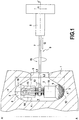
- la
figure 1 est une vue en coupe partielle d'une alvéole circonférentielle de disque de turboréacteur, dans laquelle est insérée une sonde selon l'invention ; - les
figures 2a à 2c représentent les étapes successives du procédé de contrôle de la surface d'une alvéole circonférentielle, selon l'invention.
- the
figure 1 is a partial sectional view of a circumferential cavity of a turbojet disk, in which is inserted a probe according to the invention; - the
Figures 2a to 2c represent the successive steps of the method for controlling the surface of a circumferential cavity, according to the invention.
La
Une sonde selon la présente invention est décrite à présent en référence à la
Le procédé de contrôle par courants de Foucault réalisé au moyen de la sonde présentée ci-dessus va être décrit à présent en référence aux
La
Comme représenté sur la
La
La flèche B représentée sur la
Lors du balayage circonférentiel de l'alvéole 2, les deux capteurs 9 délivrent des signaux haute fréquence proportionnels au niveau d'altération des faces latérales 3 de l'alvéole 2. Ces signaux sont ensuite filtrés et affichés sur écran sous forme d'images représentatives des résultats obtenus, exploitables par un opérateur.During the circumferential scanning of the
Claims (6)
- A method for eddy current inspection of the surface of a circumferential slot (2) formed in a turbojet disk (1) by means of a probe (6), the probe comprising a stem (7) fastened to a support (8) and a first multi-element sensor (9) and a second multi-element sensor (9),for performing the inspection, constrained to move with the stem (7) and adapted to be inserted into said circumferential slot (2), the two multi-element sensors (9) being disposed back to back and being urged resiliently in opposite directions, so as to provide good contact between the multi-element sensors (9) and the opposite surfaces (3) for inspection, and said stem (7) is mounted to pivot about its own axis (y-y') to enable the two multi-element sensors (9) to be inserted in said slot (2),the method being characterized in that it comprises the steps consisting in:a) positioning the two sensors (9) in register with the opening (5) of the slot so that a common axis (x-x') of the sensors extends perpendicularly to the axis (A-A) of the disk (1);b) moving the probe (6) in a radial direction (f2) of the disk towards the inside of the slot (2) so as to insert the two multi-element sensors (9) in said slot (2); thenc) causing the stem (7) to pivot through an angle of 90° so that the multi-element sensors (9) come into contact with the side faces (3) of the slot (2) for inspection; and finallyd) scanning the entire surface of the circumferential slot (2).
- A method according to claim 1, characterized in that during step d), the probe (6) remains stationary and the disk (1) is turned through an angle of 360°.
- An eddy current probe (6) for monitoring of the surface of a circumferential slot (2) formed in a turbojet disk (1), comprising a stem (7) fastened to a support (8) and a first multi-element sensor (9) and a second multi-element sensor (9),for performing the inspection, constrained to move with the stem (7) and adapted to be inserted into said circumferential slot (2), the two multi-element sensors (9) being disposed back to back and being urged resiliently in opposite directions, so as to provide good contact between the multi-element sensors (9) and the opposite surfaces (3) for inspection, and said stem (7) is mounted to pivot about its own axis (y-y') to enable the two multi-element sensors (9) to be inserted in said slot (2), said probe (6) being adapted to implement the process according to claim 1.
- A probe according to claim 3, characterized in that at least one spring (13) is interposed between the two multi-element sensors (9).
- A probe according to claim 3 or 4, characterized in that each multi-element sensor (9) is of a shape that corresponds to the profile of a face (3) of the slot (2) for inspection.
- A probe according to any one of claims 3 to 5, characterized in that the two multi-element sensors (9) are held back to back and are connected to the stem (7) by a sliding arrangement (14).
Applications Claiming Priority (2)
| Application Number | Priority Date | Filing Date | Title |
|---|---|---|---|
| FR0853109A FR2931242B1 (en) | 2008-05-14 | 2008-05-14 | PROBE INTENDED FOR CURRENT FOUCAULT CONTROL OF THE SURFACE OF A CIRCONFERENTIAL ALVEOLE OF A TURBOREACTOR DISC |
| PCT/FR2009/050877 WO2009147351A2 (en) | 2008-05-14 | 2009-05-13 | Probe for controlling the surface of a circumferential recess of a turbojet engine disc using foucault currents |
Publications (2)
| Publication Number | Publication Date |
|---|---|
| EP2288910A2 EP2288910A2 (en) | 2011-03-02 |
| EP2288910B1 true EP2288910B1 (en) | 2018-01-10 |
Family
ID=40039759
Family Applications (1)
| Application Number | Title | Priority Date | Filing Date |
|---|---|---|---|
| EP09757727.4A Active EP2288910B1 (en) | 2008-05-14 | 2009-05-13 | Probe for controlling the surface of a circumferential recess of a turbojet engine disc using eddy currents |
Country Status (9)
| Country | Link |
|---|---|
| US (1) | US8866471B2 (en) |
| EP (1) | EP2288910B1 (en) |
| JP (1) | JP5562942B2 (en) |
| CN (1) | CN102027363B (en) |
| BR (1) | BRPI0912627B1 (en) |
| CA (1) | CA2725797C (en) |
| FR (1) | FR2931242B1 (en) |
| RU (1) | RU2494387C2 (en) |
| WO (1) | WO2009147351A2 (en) |
Families Citing this family (5)
| Publication number | Priority date | Publication date | Assignee | Title |
|---|---|---|---|---|
| US9110036B2 (en) * | 2012-08-02 | 2015-08-18 | Olympus Ndt, Inc. | Assembly with a universal manipulator for inspecting dovetail of different sizes |
| JP6121711B2 (en) * | 2012-12-28 | 2017-04-26 | 三菱日立パワーシステムズ株式会社 | Eddy current flaw detector and eddy current flaw detection method |
| CN104181227B (en) * | 2013-05-21 | 2017-02-08 | 核动力运行研究所 | Outside cross type elastic coil eddy current probe |
| US9484209B1 (en) | 2015-11-20 | 2016-11-01 | International Business Machines Corporation | Flexible and stretchable sensors formed by patterned spalling |
| CN107991382B (en) * | 2017-10-16 | 2024-04-05 | 中广核检测技术有限公司 | Eddy current inspection device |
Citations (1)
| Publication number | Priority date | Publication date | Assignee | Title |
|---|---|---|---|---|
| US20070120559A1 (en) * | 2005-11-30 | 2007-05-31 | Yuri Plotnikov | Pulsed eddy current pipeline inspection system and method |
Family Cites Families (15)
| Publication number | Priority date | Publication date | Assignee | Title |
|---|---|---|---|---|
| DE2530816C3 (en) | 1975-07-10 | 1980-07-31 | Institut Dr. Friedrich Foerster Pruefgeraetebau, 7410 Reutlingen | Eddy current testing device for scanning the surface of a test part |
| JPH0577760U (en) * | 1991-05-28 | 1993-10-22 | 原子燃料工業株式会社 | Metal thin tube inspection device |
| US5315234A (en) * | 1992-04-03 | 1994-05-24 | General Electric Company | Eddy current device for inspecting a component having a flexible support with a plural sensor array |
| US5442286A (en) * | 1993-09-22 | 1995-08-15 | General Electric Company | Eddy current array inspection device |
| US5781007A (en) * | 1995-10-24 | 1998-07-14 | General Electric Company | Portable three axis scanner to inspect a gas turbine engine spool by eddy current or ultrasonic inspection |
| IL126315A0 (en) * | 1997-09-25 | 1999-05-09 | Siemens Power Corp | Turbine blade inspection apparatus |
| US6152698A (en) * | 1999-08-02 | 2000-11-28 | General Electric Company | Kit of articles and method for assembling articles along a holder distance |
| US6545467B1 (en) * | 2000-10-27 | 2003-04-08 | General Electric Company | Contoured surface eddy current inspection system |
| US6469503B2 (en) * | 2001-03-26 | 2002-10-22 | General Electric Company | Eddy current inspection probe and method of use |
| US6972561B2 (en) * | 2003-02-28 | 2005-12-06 | General Electric Company | Internal eddy current inspection |
| US7466126B2 (en) * | 2004-07-12 | 2008-12-16 | General Electric Company | Universal sensor probe with adjustable members configured to fit between a plurality of slot openings of varying widths |
| US7518359B2 (en) * | 2005-03-09 | 2009-04-14 | General Electric Company | Inspection of non-planar parts using multifrequency eddy current with phase analysis |
| FR2915581B1 (en) * | 2007-04-27 | 2010-09-03 | Snecma | FOUCAULT CURRENT CONTROL DEVICE OF A RECTILIGNE CAVITE |
| FR2916851B1 (en) * | 2007-05-29 | 2010-08-13 | Snecma | DEVICE FOR NON-DESTRUCTIVE CONTROL BY CURRENT STREAMS OF A PRACTICAL HOLE IN A CONDUCTIVE PIECE |
| FR2921158B1 (en) * | 2007-09-19 | 2011-05-06 | Snecma | DEVICE FOR CONTROLLING TANGENTIAL ALVEOLES OF A ROTOR DISC |
-
2008
- 2008-05-14 FR FR0853109A patent/FR2931242B1/en active Active
-
2009
- 2009-05-13 WO PCT/FR2009/050877 patent/WO2009147351A2/en active Application Filing
- 2009-05-13 CN CN200980116932XA patent/CN102027363B/en active Active
- 2009-05-13 RU RU2010150900/28A patent/RU2494387C2/en active
- 2009-05-13 BR BRPI0912627-9A patent/BRPI0912627B1/en active IP Right Grant
- 2009-05-13 US US12/992,514 patent/US8866471B2/en active Active
- 2009-05-13 JP JP2011508983A patent/JP5562942B2/en active Active
- 2009-05-13 CA CA2725797A patent/CA2725797C/en active Active
- 2009-05-13 EP EP09757727.4A patent/EP2288910B1/en active Active
Patent Citations (1)
| Publication number | Priority date | Publication date | Assignee | Title |
|---|---|---|---|---|
| US20070120559A1 (en) * | 2005-11-30 | 2007-05-31 | Yuri Plotnikov | Pulsed eddy current pipeline inspection system and method |
Also Published As
| Publication number | Publication date |
|---|---|
| US20110062954A1 (en) | 2011-03-17 |
| JP5562942B2 (en) | 2014-07-30 |
| RU2494387C2 (en) | 2013-09-27 |
| CN102027363A (en) | 2011-04-20 |
| WO2009147351A3 (en) | 2010-03-11 |
| CN102027363B (en) | 2012-09-26 |
| FR2931242B1 (en) | 2010-06-11 |
| BRPI0912627B1 (en) | 2019-06-25 |
| US8866471B2 (en) | 2014-10-21 |
| RU2010150900A (en) | 2012-06-20 |
| BRPI0912627A2 (en) | 2016-01-26 |
| CA2725797A1 (en) | 2009-12-10 |
| FR2931242A1 (en) | 2009-11-20 |
| EP2288910A2 (en) | 2011-03-02 |
| CA2725797C (en) | 2016-03-08 |
| JP2011521219A (en) | 2011-07-21 |
| WO2009147351A2 (en) | 2009-12-10 |
Similar Documents
| Publication | Publication Date | Title |
|---|---|---|
| EP2288910B1 (en) | Probe for controlling the surface of a circumferential recess of a turbojet engine disc using eddy currents | |
| EP2040069B1 (en) | Device for inspecting the tangential recesses of a rotor disc | |
| EP1733181B1 (en) | Mixed optical and mechanical sensor and associated resetting method | |
| WO2011148094A1 (en) | Device for multipoint acquisition/distribution of fluid, in particular probe for tapping pressure in a turbomachine air inlet | |
| EP1605259A1 (en) | Installation for non-destructive testing of a workpiece. | |
| CA2396038C (en) | Device for angular positioning of a vaned angle-of-attack sensor on an aircraft wall | |
| EP1986002B1 (en) | Device for inspecting a rectilinear cavity using Foucault currents. | |
| EP1986003A1 (en) | Method and installation for non-destructive testing using Foucault currents, with automatic calibration. | |
| EP3301428A1 (en) | Rake for measuring gas parameters at the outlet of a turbine engine flow section | |
| WO2009103702A2 (en) | Device and method for determining at least one value associated with the electromagnetic radiation of an object being tested | |
| CA2122067C (en) | Method and device for calibating a set of transverse profile thickness values in flat products | |
| FR2730058A1 (en) | METHOD FOR NON-DESTRUCTIVE CONTROL OF A SURFACE, ESPECIALLY IN A HOSTILE ENVIRONMENT | |
| WO2010037869A1 (en) | Improvements in the detection of deposits comprising at least one ferromagnetic material on or close to the external wall of a tube | |
| EP2795302B1 (en) | Method of fabricating a monitoring head of a nondestructive monitoring sensor based on eddy currents | |
| EP2440817B1 (en) | Nondestructive test of a sealing member | |
| CA2632661A1 (en) | Non-destructive control device using eddy currents for mounting a hole in a conducting member | |
| FR3116902A1 (en) | METHOD FOR DETECTING POSSIBLE DENTS ON A SURFACE CAPABLE OF REFLECTING LIGHT | |
| FR2777817A1 (en) | Spectacle frame groove profile and dimension sensing equipment employed on a grinding machine | |
| WO2011020969A1 (en) | Device for calibrating non-destructive testing means for a turbine engine component | |
| FR2878951A1 (en) | Rotor alignment measuring method for electricity production machine, involves measuring lateral spacings between laser beam and inner borders of stator by emitting and measuring range of another laser beam up to inner borders of stator | |
| EP3580555B1 (en) | Tube inspection unit with eddy current probe and corresponding method | |
| WO2011036193A1 (en) | Improvements to the detection of deposits comprising at least one ferromagnetic material on or in the vicinity of the outer wall of a tube | |
| EP0928409A1 (en) | Device for controlling the position of points on a part, in particular the position of hole centres made in a part, particularly a sheet metal | |
| FR2871568A1 (en) | Part e.g. compressor rotor, control installation for airplane, has chain that slides along length of vertical column, and sensor support displaced with respect to surfaces of disks, when length of rigid section of chain is varied | |
| FR2956877A1 (en) | Device for measuring passage section between two adjacent blades of distributor of turbine engine, has pair of studs in contact with blade so as to form measurement trapezoid, and measurement unit measuring surface of trapezoid |
Legal Events
| Date | Code | Title | Description |
|---|---|---|---|
| PUAI | Public reference made under article 153(3) epc to a published international application that has entered the european phase |
Free format text: ORIGINAL CODE: 0009012 |
|
| 17P | Request for examination filed |
Effective date: 20101210 |
|
| AK | Designated contracting states |
Kind code of ref document: A2 Designated state(s): AT BE BG CH CY CZ DE DK EE ES FI FR GB GR HR HU IE IS IT LI LT LU LV MC MK MT NL NO PL PT RO SE SI SK TR |
|
| AX | Request for extension of the european patent |
Extension state: AL BA RS |
|
| DAX | Request for extension of the european patent (deleted) | ||
| 17Q | First examination report despatched |
Effective date: 20170124 |
|
| GRAP | Despatch of communication of intention to grant a patent |
Free format text: ORIGINAL CODE: EPIDOSNIGR1 |
|
| INTG | Intention to grant announced |
Effective date: 20170704 |
|
| GRAS | Grant fee paid |
Free format text: ORIGINAL CODE: EPIDOSNIGR3 |
|
| GRAA | (expected) grant |
Free format text: ORIGINAL CODE: 0009210 |
|
| AK | Designated contracting states |
Kind code of ref document: B1 Designated state(s): AT BE BG CH CY CZ DE DK EE ES FI FR GB GR HR HU IE IS IT LI LT LU LV MC MK MT NL NO PL PT RO SE SI SK TR |
|
| REG | Reference to a national code |
Ref country code: GB Ref legal event code: FG4D Free format text: NOT ENGLISH |
|
| REG | Reference to a national code |
Ref country code: CH Ref legal event code: EP Ref country code: AT Ref legal event code: REF Ref document number: 962955 Country of ref document: AT Kind code of ref document: T Effective date: 20180115 |
|
| REG | Reference to a national code |
Ref country code: IE Ref legal event code: FG4D Free format text: LANGUAGE OF EP DOCUMENT: FRENCH |
|
| REG | Reference to a national code |
Ref country code: DE Ref legal event code: R096 Ref document number: 602009050338 Country of ref document: DE |
|
| REG | Reference to a national code |
Ref country code: SE Ref legal event code: TRGR |
|
| REG | Reference to a national code |
Ref country code: FR Ref legal event code: PLFP Year of fee payment: 10 |
|
| REG | Reference to a national code |
Ref country code: NL Ref legal event code: MP Effective date: 20180110 |
|
| REG | Reference to a national code |
Ref country code: AT Ref legal event code: MK05 Ref document number: 962955 Country of ref document: AT Kind code of ref document: T Effective date: 20180110 Ref country code: CH Ref legal event code: PFA Owner name: SAFRAN AIRCRAFT ENGINES, FR Free format text: FORMER OWNER: SNECMA, FR |
|
| PG25 | Lapsed in a contracting state [announced via postgrant information from national office to epo] |
Ref country code: NL Free format text: LAPSE BECAUSE OF FAILURE TO SUBMIT A TRANSLATION OF THE DESCRIPTION OR TO PAY THE FEE WITHIN THE PRESCRIBED TIME-LIMIT Effective date: 20180110 |
|
| RAP2 | Party data changed (patent owner data changed or rights of a patent transferred) |
Owner name: SAFRAN AIRCRAFT ENGINES |
|
| PG25 | Lapsed in a contracting state [announced via postgrant information from national office to epo] |
Ref country code: ES Free format text: LAPSE BECAUSE OF FAILURE TO SUBMIT A TRANSLATION OF THE DESCRIPTION OR TO PAY THE FEE WITHIN THE PRESCRIBED TIME-LIMIT Effective date: 20180110 Ref country code: CY Free format text: LAPSE BECAUSE OF FAILURE TO SUBMIT A TRANSLATION OF THE DESCRIPTION OR TO PAY THE FEE WITHIN THE PRESCRIBED TIME-LIMIT Effective date: 20180110 Ref country code: FI Free format text: LAPSE BECAUSE OF FAILURE TO SUBMIT A TRANSLATION OF THE DESCRIPTION OR TO PAY THE FEE WITHIN THE PRESCRIBED TIME-LIMIT Effective date: 20180110 Ref country code: LT Free format text: LAPSE BECAUSE OF FAILURE TO SUBMIT A TRANSLATION OF THE DESCRIPTION OR TO PAY THE FEE WITHIN THE PRESCRIBED TIME-LIMIT Effective date: 20180110 Ref country code: HR Free format text: LAPSE BECAUSE OF FAILURE TO SUBMIT A TRANSLATION OF THE DESCRIPTION OR TO PAY THE FEE WITHIN THE PRESCRIBED TIME-LIMIT Effective date: 20180110 Ref country code: NO Free format text: LAPSE BECAUSE OF FAILURE TO SUBMIT A TRANSLATION OF THE DESCRIPTION OR TO PAY THE FEE WITHIN THE PRESCRIBED TIME-LIMIT Effective date: 20180410 |
|
| PG25 | Lapsed in a contracting state [announced via postgrant information from national office to epo] |
Ref country code: BG Free format text: LAPSE BECAUSE OF FAILURE TO SUBMIT A TRANSLATION OF THE DESCRIPTION OR TO PAY THE FEE WITHIN THE PRESCRIBED TIME-LIMIT Effective date: 20180410 Ref country code: AT Free format text: LAPSE BECAUSE OF FAILURE TO SUBMIT A TRANSLATION OF THE DESCRIPTION OR TO PAY THE FEE WITHIN THE PRESCRIBED TIME-LIMIT Effective date: 20180110 Ref country code: PL Free format text: LAPSE BECAUSE OF FAILURE TO SUBMIT A TRANSLATION OF THE DESCRIPTION OR TO PAY THE FEE WITHIN THE PRESCRIBED TIME-LIMIT Effective date: 20180110 Ref country code: IS Free format text: LAPSE BECAUSE OF FAILURE TO SUBMIT A TRANSLATION OF THE DESCRIPTION OR TO PAY THE FEE WITHIN THE PRESCRIBED TIME-LIMIT Effective date: 20180510 Ref country code: GR Free format text: LAPSE BECAUSE OF FAILURE TO SUBMIT A TRANSLATION OF THE DESCRIPTION OR TO PAY THE FEE WITHIN THE PRESCRIBED TIME-LIMIT Effective date: 20180411 Ref country code: LV Free format text: LAPSE BECAUSE OF FAILURE TO SUBMIT A TRANSLATION OF THE DESCRIPTION OR TO PAY THE FEE WITHIN THE PRESCRIBED TIME-LIMIT Effective date: 20180110 |
|
| PG25 | Lapsed in a contracting state [announced via postgrant information from national office to epo] |
Ref country code: MT Free format text: LAPSE BECAUSE OF FAILURE TO SUBMIT A TRANSLATION OF THE DESCRIPTION OR TO PAY THE FEE WITHIN THE PRESCRIBED TIME-LIMIT Effective date: 20180110 |
|
| REG | Reference to a national code |
Ref country code: DE Ref legal event code: R097 Ref document number: 602009050338 Country of ref document: DE |
|
| PG25 | Lapsed in a contracting state [announced via postgrant information from national office to epo] |
Ref country code: RO Free format text: LAPSE BECAUSE OF FAILURE TO SUBMIT A TRANSLATION OF THE DESCRIPTION OR TO PAY THE FEE WITHIN THE PRESCRIBED TIME-LIMIT Effective date: 20180110 Ref country code: EE Free format text: LAPSE BECAUSE OF FAILURE TO SUBMIT A TRANSLATION OF THE DESCRIPTION OR TO PAY THE FEE WITHIN THE PRESCRIBED TIME-LIMIT Effective date: 20180110 |
|
| PLBE | No opposition filed within time limit |
Free format text: ORIGINAL CODE: 0009261 |
|
| STAA | Information on the status of an ep patent application or granted ep patent |
Free format text: STATUS: NO OPPOSITION FILED WITHIN TIME LIMIT |
|
| PG25 | Lapsed in a contracting state [announced via postgrant information from national office to epo] |
Ref country code: DK Free format text: LAPSE BECAUSE OF FAILURE TO SUBMIT A TRANSLATION OF THE DESCRIPTION OR TO PAY THE FEE WITHIN THE PRESCRIBED TIME-LIMIT Effective date: 20180110 Ref country code: CZ Free format text: LAPSE BECAUSE OF FAILURE TO SUBMIT A TRANSLATION OF THE DESCRIPTION OR TO PAY THE FEE WITHIN THE PRESCRIBED TIME-LIMIT Effective date: 20180110 Ref country code: SK Free format text: LAPSE BECAUSE OF FAILURE TO SUBMIT A TRANSLATION OF THE DESCRIPTION OR TO PAY THE FEE WITHIN THE PRESCRIBED TIME-LIMIT Effective date: 20180110 |
|
| REG | Reference to a national code |
Ref country code: CH Ref legal event code: PL |
|
| 26N | No opposition filed |
Effective date: 20181011 |
|
| REG | Reference to a national code |
Ref country code: BE Ref legal event code: MM Effective date: 20180531 |
|
| PG25 | Lapsed in a contracting state [announced via postgrant information from national office to epo] |
Ref country code: MC Free format text: LAPSE BECAUSE OF FAILURE TO SUBMIT A TRANSLATION OF THE DESCRIPTION OR TO PAY THE FEE WITHIN THE PRESCRIBED TIME-LIMIT Effective date: 20180110 |
|
| REG | Reference to a national code |
Ref country code: IE Ref legal event code: MM4A |
|
| PG25 | Lapsed in a contracting state [announced via postgrant information from national office to epo] |
Ref country code: LI Free format text: LAPSE BECAUSE OF NON-PAYMENT OF DUE FEES Effective date: 20180531 Ref country code: SI Free format text: LAPSE BECAUSE OF FAILURE TO SUBMIT A TRANSLATION OF THE DESCRIPTION OR TO PAY THE FEE WITHIN THE PRESCRIBED TIME-LIMIT Effective date: 20180110 Ref country code: CH Free format text: LAPSE BECAUSE OF NON-PAYMENT OF DUE FEES Effective date: 20180531 |
|
| PG25 | Lapsed in a contracting state [announced via postgrant information from national office to epo] |
Ref country code: LU Free format text: LAPSE BECAUSE OF NON-PAYMENT OF DUE FEES Effective date: 20180513 |
|
| PG25 | Lapsed in a contracting state [announced via postgrant information from national office to epo] |
Ref country code: IE Free format text: LAPSE BECAUSE OF NON-PAYMENT OF DUE FEES Effective date: 20180513 |
|
| PG25 | Lapsed in a contracting state [announced via postgrant information from national office to epo] |
Ref country code: BE Free format text: LAPSE BECAUSE OF NON-PAYMENT OF DUE FEES Effective date: 20180531 |
|
| PG25 | Lapsed in a contracting state [announced via postgrant information from national office to epo] |
Ref country code: TR Free format text: LAPSE BECAUSE OF FAILURE TO SUBMIT A TRANSLATION OF THE DESCRIPTION OR TO PAY THE FEE WITHIN THE PRESCRIBED TIME-LIMIT Effective date: 20180110 |
|
| PG25 | Lapsed in a contracting state [announced via postgrant information from national office to epo] |
Ref country code: PT Free format text: LAPSE BECAUSE OF FAILURE TO SUBMIT A TRANSLATION OF THE DESCRIPTION OR TO PAY THE FEE WITHIN THE PRESCRIBED TIME-LIMIT Effective date: 20180110 Ref country code: HU Free format text: LAPSE BECAUSE OF FAILURE TO SUBMIT A TRANSLATION OF THE DESCRIPTION OR TO PAY THE FEE WITHIN THE PRESCRIBED TIME-LIMIT; INVALID AB INITIO Effective date: 20090513 |
|
| PG25 | Lapsed in a contracting state [announced via postgrant information from national office to epo] |
Ref country code: MK Free format text: LAPSE BECAUSE OF NON-PAYMENT OF DUE FEES Effective date: 20180110 |
|
| PGFP | Annual fee paid to national office [announced via postgrant information from national office to epo] |
Ref country code: IT Payment date: 20230420 Year of fee payment: 15 Ref country code: FR Payment date: 20230420 Year of fee payment: 15 Ref country code: DE Payment date: 20230419 Year of fee payment: 15 |
|
| PGFP | Annual fee paid to national office [announced via postgrant information from national office to epo] |
Ref country code: SE Payment date: 20230419 Year of fee payment: 15 |
|
| PGFP | Annual fee paid to national office [announced via postgrant information from national office to epo] |
Ref country code: GB Payment date: 20230420 Year of fee payment: 15 |