EP2288009A2 - Linearmotor der Bauart mit mehreren beweglichen Spulen - Google Patents
Linearmotor der Bauart mit mehreren beweglichen Spulen Download PDFInfo
- Publication number
- EP2288009A2 EP2288009A2 EP10172033A EP10172033A EP2288009A2 EP 2288009 A2 EP2288009 A2 EP 2288009A2 EP 10172033 A EP10172033 A EP 10172033A EP 10172033 A EP10172033 A EP 10172033A EP 2288009 A2 EP2288009 A2 EP 2288009A2
- Authority
- EP
- European Patent Office
- Prior art keywords
- moving part
- thrust
- small
- thrust moving
- armature coils
- Prior art date
- Legal status (The legal status is an assumption and is not a legal conclusion. Google has not performed a legal analysis and makes no representation as to the accuracy of the status listed.)
- Withdrawn
Links
Images



Classifications
-
- H—ELECTRICITY
- H02—GENERATION; CONVERSION OR DISTRIBUTION OF ELECTRIC POWER
- H02K—DYNAMO-ELECTRIC MACHINES
- H02K41/00—Propulsion systems in which a rigid body is moved along a path due to dynamo-electric interaction between the body and a magnetic field travelling along the path
- H02K41/02—Linear motors; Sectional motors
- H02K41/03—Synchronous motors; Motors moving step by step; Reluctance motors
- H02K41/031—Synchronous motors; Motors moving step by step; Reluctance motors of the permanent magnet type
-
- H—ELECTRICITY
- H02—GENERATION; CONVERSION OR DISTRIBUTION OF ELECTRIC POWER
- H02K—DYNAMO-ELECTRIC MACHINES
- H02K41/00—Propulsion systems in which a rigid body is moved along a path due to dynamo-electric interaction between the body and a magnetic field travelling along the path
- H02K41/02—Linear motors; Sectional motors
- H02K41/035—DC motors; Unipolar motors
- H02K41/0352—Unipolar motors
- H02K41/0354—Lorentz force motors, e.g. voice coil motors
- H02K41/0356—Lorentz force motors, e.g. voice coil motors moving along a straight path
-
- H—ELECTRICITY
- H02—GENERATION; CONVERSION OR DISTRIBUTION OF ELECTRIC POWER
- H02K—DYNAMO-ELECTRIC MACHINES
- H02K2213/00—Specific aspects, not otherwise provided for and not covered by codes H02K2201/00 - H02K2211/00
- H02K2213/03—Machines characterised by numerical values, ranges, mathematical expressions or similar information
-
- H—ELECTRICITY
- H02—GENERATION; CONVERSION OR DISTRIBUTION OF ELECTRIC POWER
- H02K—DYNAMO-ELECTRIC MACHINES
- H02K3/00—Details of windings
- H02K3/46—Fastening of windings on the stator or rotor structure
- H02K3/47—Air-gap windings, i.e. iron-free windings
Definitions
- the present invention relates to multihead-type coreless linear motors.
- Japanese Unexamined Patent Application Publication No. 2001-211630 published August 3, 2001 , discloses an example of a coreless linear motor that is used as a feeder mounted on a table of a glass-substrate conveying apparatus, a semiconductor manufacturing apparatus, a machine tool, or the like.
- This coreless linear motor is of a multihead type where a plurality of moving parts of the same size are arranged on the same stator, so that the plurality of moving parts can be driven separately.
- each moving part that constitutes an armature includes a moving part base and a plurality of armature coils that are closely wounded and connected in three phases.
- the stator that constitutes a field magnet is disposed opposite the armature with a magnetic gap therebetween.
- the stator includes field yokes and a plurality of permanent magnets that are linearly arranged along the length of the field yokes such that different magnetic poles appear alternately.
- a configuration of moving parts for a multihead-type coreless linear motor will be described in detail here.
- the length of each moving part can be determined depending on the necessary thrust for each work.
- the motor may be possible to design the motor on the basis of the small-thrust moving part, so as to provide a configuration in which the small-thrust moving part corresponds to 1 set and the large-thrust moving part corresponds to 10 sets.
- the resulting narrow pole pitches may often cause leakage of magnetic field fluxes and degrade the efficiency of the motor. Therefore, it is difficult to reduce the size of the motor.
- An object of the present invention is to provide a multihead-type coreless linear motor that can be minimized in size, even if there is a significant difference in necessary thrust between a plurality of works to be placed on respective moving parts of the linear motor.
- a multihead-type coreless linear motor includes a permanent field magnet having P permanent magnets that are linearly arranged such that different magnetic poles appear alternately; and an armature disposed opposite the permanent field magnet with a magnetic gap therebetween, the armature having M armature coils that are closely wounded and connected in three phases.
- One of the armature and the permanent field magnet is configured as a moving part and the other is configured as a stator.
- a plurality of moving parts are arranged on the same stator, and are driven separately relative to the stator.
- the plurality of moving parts include a large-thrust moving part and a small-thrust moving part that are different in relationship with the stator, the relationship being determined by the number of magnetic poles P of the permanent magnets and the number of armature coils M.
- the multihead-type coreless linear motor according to the present invention, a plurality of moving parts that are different in the relationship between the number of magnetic poles and the number of coils are arranged on the same stator. Therefore, even if there is a significant difference in necessary thrust between a plurality of works, it is possible to reduce the motor size to a minimum and realize a compact apparatus.
- Linear motors illustrated in the drawings are configured such that a moving part is an armature and a stator is a field magnet.
- Fig. 1A is a side view of a multihead-type coreless linear motor according to a first embodiment of the present invention.
- Fig. 1B is a front view of Fig. 1A .
- the linear motor illustrated in Fig. 1A includes a large-thrust moving part 11a, a small-thrust moving part 12b, a large-thrust coil 31a, and a small-thrust coil 32b.
- the first embodiment is different from the related art in that a plurality of moving parts 1 (i.e., the large-thrust moving part 11a and the small-thrust moving part 12b) that are different in relationship determined by the number of magnetic poles P of a permanent field magnet constituting a stator and the number of armature coils M constituting a moving part are arranged on the same stator 4.
- a plurality of moving parts 1 i.e., the large-thrust moving part 11a and the small-thrust moving part 12b
- the length of the large-thrust moving part 11a is 4 ⁇ p ⁇ N, where ⁇ p is a pole pitch and N is an integer greater than or equal to 1.
- the length of the small-thrust moving part 12b is 2 ⁇ p.
- Fig. 12 shows a comparison table that compares, for each embodiment, motor characteristics and the levels of necessary thrust calculated on the basis of the motor characteristics, between a large-thrust moving part and a small-thrust moving part on which works are to be placed.
- motor characteristics of a large-thrust moving part are taken as 100% in each embodiment.
- coils for the large-thrust moving part and the small-thrust moving part have the same conductor diameter, and if the number of coils for each phase is more than one, these coils are connected in parallel.
- Fig. 12 shows a comparison table that compares, for each embodiment, motor characteristics and the levels of necessary thrust calculated on the basis of the motor characteristics, between a large-thrust moving part and a small-thrust moving part on which works are to be placed.
- motor characteristics of a large-thrust moving part are taken as 100% in each embodiment.
- coils for the large-thrust moving part and the small-thrust moving part have the same conductor diameter, and if the number of coils for each phase is
- a large-thrust moving part is indicated by A
- a small-thrust moving part is indicated by B
- a length of a moving part is indicated by L.
- the motor characteristics include a winding factor indicated by Cw, the number of winding turns indicated by Nw, an inductive voltage indicated by V, a winding resistance indicated by Rw, and a motor constant indicated by Cm. Additionally, a maximum thrust is indicated by P.
- the length of the large-thrust moving part 11a and that of the small-thrust moving part 12b are set to 4 ⁇ p ⁇ N (where N is an integer greater than or equal to 1) and 2 ⁇ p, respectively.
- the two moving parts, the large-thrust moving part 11a and the small-thrust moving part 12b indicated by A and B, respectively, in Fig. 12 are thus different in winding factor (Cw) (the ratio of Cw for A to that for B is 100 to 67) and the number of winding turns (Nw) (the ratio of Nw for A to that for B is 100 to 48) of the armature coils.
- Cw winding factor
- Nw number of winding turns
- the two moving parts are different in inductive voltage constant (V) (the ratio of thrust constant for A to that for B is 100 to 32). Then, since winding spaces of the armature coils for the two moving parts are different, the two moving parts are different in winding resistance (Rw) (the ratio of Rw for A to that for B is 100 to 44). Moreover, when the two moving parts are different in inductive voltage constant and winding resistance, the two moving parts are also different in motor constant (Cm) (the ratio of Cm for A to that for B is 100 to 48).
- V inductive voltage constant
- Rw winding resistance
- Cm motor constant
- the levels of necessary thrust (P) for the two moving parts can be obtained (the ratio of P for A to that for B is 100 to 23).
- the linear motor such that the large-thrust moving part 11a and the small-thrust moving part 12b can be adjusted to lengths (or sizes) that are most appropriate for the sizes of works (or loads) to be placed on the respective moving parts (i.e., most appropriate for the difference between the levels of necessary thrust required for the respective moving parts).
- Fig. 2A is a side view of a multihead-type coreless linear motor according to a second embodiment of the present invention.
- Fig. 2B is a front view of Fig. 2A.
- Fig. 3 is an enlarged cross-sectional plan view illustrating how a stator and a small-thrust moving part of Fig. 2A are arranged.
- the linear motor illustrated in Fig. 2A includes the large-thrust moving part 11a, a small-thrust moving part 12c, the large-thrust coil 31a, and a small-thrust coil 32c.
- the small-thrust coil 32c includes a U-phase coil 32u, a V-phase coil 32v, and a W-phase coil 32w'.
- the length of the large-thrust moving part 11a is 4 ⁇ p ⁇ N, where ⁇ p is a pole pitch and N is an integer greater than or equal to 1.
- the W-phase coil 32w' is displaced by an electrical angle of 180° to reverse the winding direction of the W-phase coil 32w', so that the small-thrust moving part 12c has a length of (4/3) ⁇ p.
- the W-phase coil 32w' for the small-thrust moving part 12c is displaced by an electrical angle of 180°, and the lengths of the large-thrust moving part 11a and the small-thrust moving part 12c are set to 4 ⁇ p ⁇ N (where N is an integer greater than or equal to 1) and (4/3) ⁇ p, respectively.
- the two moving parts, the large-thrust moving part 11a and the small-thrust moving part 12c indicated by A and B, respectively, in Fig. 12 are thus different in winding factor (Cw) (the ratio of Cw for A to that for B is 100 to 67) and the number of winding turns (Nw) (the ratio of Nw for A to that for B is 100 to 48) of the armature coils.
- the two moving parts are different in inductive voltage constant (V) (the ratio of thrust constant for A to that for B is 100 to 32). Then, since winding spaces of the armature coils for the two moving parts are different, the two moving parts are different in winding resistance (Rw) (the ratio of Rw for A to that for B is 100 to 88). Moreover, when the two moving parts are different in inductive voltage constant and winding resistance, the two moving parts are also different in motor constant (Cm) (the ratio of Cm for A to that for B is 100 to 34).
- V inductive voltage constant
- Rw winding resistance
- Cm motor constant
- the levels of necessary thrust (P) for the two moving parts can be obtained (the ratio of P for A to that for B is 100 to 12).
- the linear motor such that the large-thrust moving part 11a and the small-thrust moving part 12c can be adjusted to lengths (or sizes) that are most appropriate for the sizes of works (or loads) to be placed on the respective moving parts (i.e., most appropriate for the difference between the levels of necessary thrust required for the respective moving parts).
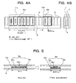
- Fig. 4A is a side view of a multihead-type coreless linear motor according to a third embodiment of the present invention.
- Fig. 4B is a front view of Fig. 4A.
- Fig. 5 is an enlarged cross-sectional plan view illustrating how a stator and a small-thrust moving part of Fig. 4A are arranged.
- the linear motor illustrated in Fig. 4A includes the large-thrust moving part 11a, a small-thrust moving part 12d, the large-thrust coil 31a, and a small-thrust coil 32d.
- the small-thrust coil 32d includes the U-phase coil 32u, the V-phase coil 32v, and a W-phase coil 32w.
- the length of the large-thrust moving part 11a is 4 ⁇ p ⁇ N, where ⁇ p is a pole pitch and N is an integer greater than or equal to 1.
- the V-phase coil 32v is displaced by an electrical angle of 360°, so that the small-thrust moving part 12d has a length of (8/3) ⁇ p.
- the V-phase coil 32v for the small-thrust moving part 12d is displaced by an electrical angle of 360°, and the lengths of the large-thrust moving part 11a and the small-thrust moving part 12d are set to 4 ⁇ p ⁇ N (where N is an integer greater than or equal to 1) and (8/3) ⁇ p, respectively. Since the two moving parts, the large-thrust moving part 11a and the small-thrust moving part 12d indicated by A and B, respectively, in Fig. 12 , are the same in winding factor (Cw) and the number of winding turns (Nw) of the armature coils, there is no difference in inductive voltage constant (V) between the two moving parts.
- Cw winding factor
- Nw number of winding turns
- the two moving parts are different in winding resistance (Rw) (the ratio of Rw for A to that for B is 100 to 200).
- the two moving parts are also different in motor constant (Cm) (the ratio of Cm for A to that for B is 100 to 71).
- the linear motor such that the large-thrust moving part 11a and the small-thrust moving part 12d can be adjusted to lengths (or sizes) that are most appropriate for the sizes of works (or loads) to be placed on the respective moving parts (i.e., most appropriate for the difference between the levels of necessary thrust required for the respective moving parts).
- Fig. 6A is a side view of a multihead-type coreless linear motor according to a fourth embodiment of the present invention.
- Fig. 6B is a front view of Fig. 6A.
- Fig. 7 is an enlarged cross-sectional plan view illustrating how a stator and a small-thrust moving part of Fig. 6A are arranged.
- the linear motor illustrated in Fig. 6A includes the large-thrust moving part 11a, a small-thrust moving part 12e, the large-thrust coil 31a, and a small-thrust coil 32e.
- the small-thrust coil 32e includes the U-phase coil 32u, the V-phase coil 32v, and the W-phase coil 32w.
- the length of the large-thrust moving part 11a is 4 ⁇ p ⁇ N, where ⁇ p is a pole pitch and N is an integer greater than or equal to 1.
- the W-phase coil 32w is displaced by an electrical angle of 360°, so that the small-thrust moving part 12e has a length of (10/3) ⁇ p.
- the W-phase coil 32w for the small-thrust moving part 12e is displaced by an electrical angle of 360°, and the lengths of the large-thrust moving part 11a and the small-thrust moving part 12e are set to 4 ⁇ p ⁇ N (where N is an integer greater than or equal to 1) and (10/3) ⁇ p, respectively.
- the two moving parts, the large-thrust moving part 11a and the small-thrust moving part 12e indicated by A and B, respectively, in Fig. 12 are thus different in winding factor (Cw) (the ratio of Cw for A to that for B is 100 to 98) and the number of winding turns (Nw) (the ratio of Nw for A to that for B is 100 to 127) of the armature coils.
- Cw winding factor
- Nw number of winding turns
- the two moving parts are different in inductive voltage constant (V) (the ratio of thrust constant for A to that for B is 100 to 124). Then, since winding spaces of the armature coils for the two moving parts are different, the two moving parts are different in winding resistance (Rw) (the ratio of Rw for A to that for B is 100 to 263). Moreover, when the two moving parts are different in inductive voltage constant and winding resistance, the two moving parts are also different in motor constant (Cm) (the ratio of Cm for A to that for B is 100 to 77).
- V inductive voltage constant
- Rw winding resistance
- Cm motor constant
- the levels of necessary thrust (P) for the two moving parts can be obtained (the ratio of P for A to that for B is 100 to 59).
- the linear motor such that the large-thrust moving part 11a and the small-thrust moving part 12e can be adjusted to lengths (or sizes) that are most appropriate for the sizes of works (or loads) to be placed on the respective moving parts (i.e., most appropriate for the difference between the levels of necessary thrust required for the respective moving parts).
- Fig. 8A is a side view of a multihead-type coreless linear motor according to a fifth embodiment of the present invention.
- Fig. 8B is a front view of Fig. 8A .
- the linear motor illustrated in Fig. 8A includes a large-thrust moving part 11b, the small-thrust moving part 12b, a large-thrust coil 31b, and the small-thrust coil 32b.
- the length of the large-thrust moving part 11b is 5 ⁇ p ⁇ N, where ⁇ p is a pole pitch and N is an integer greater than or equal to 1.
- the length of the small-thrust moving part 12b is 2 ⁇ p.
- the lengths of the large-thrust moving part 11b and the small-thrust moving part 12b are set to 5 ⁇ p ⁇ N (where N is an integer greater than or equal to 1) and 2 ⁇ p, respectively.
- the two moving parts, the large-thrust moving part 11b and the small-thrust moving part 12b indicated by A and B, respectively, in Fig. 12 are thus different in winding factor (Cw) (the ratio Cw for A to that for B is 100 to 68) and the number of winding turns (Nw) (the ratio of Nw for A to that for B is 100 to 38) of the armature coils. Therefore, the two moving parts are different in inductive voltage constant (V) (the ratio of thrust constant for A to that for B is 100 to 26).
- V inductive voltage constant
- the two moving parts are different in winding resistance (Rw) (the ratio of Rw for A to that for B is 100 to 34).
- Rw winding resistance
- Cm motor constant
- the two moving parts are also different in motor constant (Cm) (the ratio of Cm for A to that for B is 100 to 44).
- the linear motor such that the large-thrust moving part 11b and the small-thrust moving part 12b can be adjusted to lengths (or sizes) that are most appropriate for the sizes of works (or loads) to be placed on the respective moving parts (i.e., most appropriate for the difference between the levels of necessary thrust required for the respective moving parts).
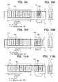
- Fig. 9A is a side view of a multihead-type coreless linear motor according to a sixth embodiment of the present invention.
- Fig. 9B is a front view of Fig. 9A . Note that how a stator and a small-thrust moving part of Fig. 9A are arranged is illustrated in Fig. 3 .
- the linear motor illustrated in Fig. 9A includes the large-thrust moving part 11b, the small-thrust moving part 12c, the large-thrust coil 31b, and the small-thrust coil 32c.
- the length of the large-thrust moving part 11b is 5 ⁇ p ⁇ N, where ⁇ p is a pole pitch and N is an integer greater than or equal to 1.
- the W-phase coil 32w' is displaced by an electrical angle of 180° to reverse the winding direction of the W-phase coil 32w', so that the small-thrust moving part 12c has a length of (4/3) ⁇ p.
- the W-phase coil 32w' for the small-thrust moving part 12c is displaced by an electrical angle of 180°, and the lengths of the large-thrust moving part 11b and the small-thrust moving part 12c are set to 5 ⁇ p ⁇ N (where N is an integer greater than or equal to 1) and (4/3) ⁇ p, respectively.
- the two moving parts, the large-thrust moving part 11b and the small-thrust moving part 12c indicated by A and B, respectively, in Fig. 12 are thus different in winding factor (Cw) (the ratio of Cw for A to that for B is 100 to 68) and the number of winding turns (Nw) (the ratio of Nw for A to that for B is 100 to 38) of the armature coils.
- the two moving parts are different in inductive voltage constant (V) (the ratio of thrust constant for A to that for B is 100 to 26). Then, since winding spaces of the armature coils for the two moving parts are different, the two moving parts are different in winding resistance (Rw) (the ratio Rw for A to that for B is 100 to 67). Moreover, when the two moving parts are different in inductive voltage constant and winding resistance, the two moving parts are also different in motor constant (Cm) (the ratio of Cm for A to that for B is 100 to 31).
- V inductive voltage constant
- Rw winding resistance
- Cm motor constant
- the levels of necessary thrust (P) for the two moving parts can be obtained (the ratio of P for A to that for B is 100 to 10).
- the linear motor such that the large-thrust moving part 11b and the small-thrust moving part 12c can be adjusted to lengths (or sizes) that are most appropriate for the sizes of works (or loads) to be placed on the respective moving parts (i.e., most appropriate for the difference between the levels of necessary thrust required for the respective moving parts).
- Fig. 10A is a side view of a multihead-type coreless linear motor according to a seventh embodiment of the present invention.
- Fig. 10B is a front view of Fig. 10A . Note that how a stator and a small-thrust moving part of Fig. 10A are arranged is illustrated in Fig. 5 .
- the linear motor illustrated in Fig. 10A includes the large-thrust moving part 11b, the small-thrust moving part 12d, the large-thrust coil 31b, and the small-thrust coil 32d.
- the length of the large-thrust moving part 11b is 5 ⁇ p ⁇ N, where ⁇ p is a pole pitch and N is an integer greater than or equal to 1.
- the V-phase coil 32v is displaced by an electrical angle of 360°, so that the small-thrust moving part 12d has a length of (8/3) ⁇ p.
- the V-phase coil 32v for the small-thrust moving part 12d is displaced by an electrical angle of 360°, and the lengths of the large-thrust moving part 11b and the small-thrust moving part 12d are set to 5 ⁇ p ⁇ N (where N is an integer greater than or equal to 1) and (8/3) ⁇ p, respectively.
- the two moving parts, the large-thrust moving part 11b and the small-thrust moving part 12d indicated by A and B, respectively, in Fig. 12 are thus different in winding factor (Cw) (the ratio of Cw for A to that for B is 100 to 102) and the number of winding turns (Nw) (the ratio of Nw for A to that for B is 100 to 79) of the armature coils.
- Cw winding factor
- Nw number of winding turns
- the two moving parts are different in inductive voltage constant (V) (the ratio of thrust constant for A to that for B is 100 to 80). Then, since winding spaces of the armature coils for the two moving parts are different, the two moving parts are different in winding resistance (Rw) (the ratio of Rw for A to that for B is 100 to 152). Moreover, when the two moving parts are different in inductive voltage constant and winding resistance, the two moving parts are also different in motor constant (Cm) (the ratio of Cm for A to that for B is 100 to 65).
- V inductive voltage constant
- Rw winding resistance
- Cm motor constant
- the levels of necessary thrust (P) for the two moving parts can be obtained (the ratio of P for A to that for B is 100 to 43).
- the linear motor such that the large-thrust moving part 11b and the small-thrust moving part 12d can be adjusted to lengths (or sizes) that are most appropriate for the sizes of works (or loads) to be placed on the respective moving parts (i.e., most appropriate for the difference between the levels of necessary thrust required for the respective moving parts).
- the seventh embodiment where a large-thrust moving part and a small-thrust moving part that are different in the relationship between the number of magnetic poles and the number of coils are arranged on the same stator, even if there is a significant difference between the levels of necessary thrust for works to be placed on the respective moving parts, it is possible to reduce the motor size to a minimum.
- Fig. 11A is a side view of a multihead-type coreless linear motor according to an eighth embodiment of the present invention.
- Fig. 11B is a front view of Fig. 11A . Note that how a stator and a small-thrust moving part of Fig. 11A are arranged is illustrated in Fig. 7 .
- the linear motor illustrated in Fig. 11A includes the large-thrust moving part 11b, the small-thrust moving part 12e, the large-thrust coil 31b, and the small-thrust coil 32e.
- the length of the large-thrust moving part 11b is 5 ⁇ p ⁇ N, where ⁇ p is a pole pitch and N is an integer greater than or equal to 1.
- the W-phase coil 32w is displaced by an electrical angle of 360°, so that the small-thrust moving part 12e has a length of (10/3) ⁇ p.
- the W-phase coil 32w for the small-thrust moving part 12e is displaced by an electrical angle of 360°, and the lengths of the large-thrust moving part 11b and the small-thrust moving part 12e are set to 5 ⁇ p ⁇ N (where N is an integer greater than or equal to 1) and (10/3) ⁇ p, respectively. Since the two moving parts, the large-thrust moving part 11b and the small-thrust moving part 12e indicated by A and B, respectively, in Fig. 12 , are the same in winding factor (Cw) and the number of winding turns (Nw) of the armature coils, there is no difference in inductive voltage constant (V) between the two moving parts.
- Cw winding factor
- Nw number of winding turns
- the two moving parts are different in winding resistance (Rw) (the ratio of Rw for A to that for B is 100 to 200).
- the two moving parts are also different in motor constant (Cm) (the ratio of Cm for A to that for B is 100 to 71).
- the linear motor such that the large-thrust moving part 11b and the small-thrust moving part 12e can be adjusted to lengths (or sizes) that are most appropriate for the sizes of works (or loads) to be placed on the respective moving parts (i.e., most appropriate for the difference between the levels of necessary thrust required for the respective moving parts).
- An armature and a field magnet are configured as a moving part and a stator, respectively, in the embodiments described above.
- an armature and a field magnet may be configured as a stator and a moving part, respectively.
- a multihead-type coreless linear motor In a multihead-type coreless linear motor according to the present invention, a plurality of moving parts that are different in the relationship between the number of magnetic poles of a permanent field magnet and the number of armature coils are arranged on the same stator.
- a major work e.g., a glass substrate
- a small work e.g., a cable
Landscapes
- Engineering & Computer Science (AREA)
- Physics & Mathematics (AREA)
- Chemical & Material Sciences (AREA)
- Combustion & Propulsion (AREA)
- Electromagnetism (AREA)
- Power Engineering (AREA)
- Linear Motors (AREA)
Applications Claiming Priority (2)
| Application Number | Priority Date | Filing Date | Title |
|---|---|---|---|
| JP2009189574 | 2009-08-18 | ||
| JP2010022597A JP5018910B2 (ja) | 2009-08-18 | 2010-02-03 | マルチヘッド形コアレスリニアモータ |
Publications (1)
| Publication Number | Publication Date |
|---|---|
| EP2288009A2 true EP2288009A2 (de) | 2011-02-23 |
Family
ID=42711927
Family Applications (1)
| Application Number | Title | Priority Date | Filing Date |
|---|---|---|---|
| EP10172033A Withdrawn EP2288009A2 (de) | 2009-08-18 | 2010-08-05 | Linearmotor der Bauart mit mehreren beweglichen Spulen |
Country Status (4)
| Country | Link |
|---|---|
| US (1) | US8427015B2 (de) |
| EP (1) | EP2288009A2 (de) |
| JP (1) | JP5018910B2 (de) |
| CN (1) | CN101997387B (de) |
Cited By (1)
| Publication number | Priority date | Publication date | Assignee | Title |
|---|---|---|---|---|
| CN102403871A (zh) * | 2010-09-13 | 2012-04-04 | 株式会社安川电机 | 带铁芯的多头型直线电机 |
Families Citing this family (6)
| Publication number | Priority date | Publication date | Assignee | Title |
|---|---|---|---|---|
| CN102195439B (zh) * | 2011-05-26 | 2013-06-12 | 清华大学 | 一种多定子多动子阵列式直线电机驱动装置 |
| JP6318945B2 (ja) * | 2014-07-24 | 2018-05-09 | 株式会社安川電機 | コアレスリニアモータ電機子、コアレスリニアモータ及びコアレスリニアモータ電機子の製造方法 |
| US10384914B2 (en) * | 2015-09-10 | 2019-08-20 | Otis Elevator Company | Elevator support structure |
| CN109217614A (zh) * | 2017-07-06 | 2019-01-15 | 上海合栗智能科技有限公司 | 线性马达及其动子 |
| CN107623426A (zh) * | 2017-07-28 | 2018-01-23 | 柴民 | 一种线性驱动装置及线性电机 |
| EP3661033A1 (de) | 2018-11-27 | 2020-06-03 | B&R Industrial Automation GmbH | Transporteinrichtung in form eines langstatorlinearmotors |
Citations (1)
| Publication number | Priority date | Publication date | Assignee | Title |
|---|---|---|---|---|
| JP2001211630A (ja) | 2000-01-20 | 2001-08-03 | Yaskawa Electric Corp | リニアスライダ |
Family Cites Families (10)
| Publication number | Priority date | Publication date | Assignee | Title |
|---|---|---|---|---|
| JPS534202B2 (de) * | 1972-03-08 | 1978-02-15 | ||
| JPS6331465A (ja) * | 1986-07-25 | 1988-02-10 | Asahi Chem Ind Co Ltd | リニア直流モ−タ |
| JPH03222669A (ja) * | 1990-01-26 | 1991-10-01 | Shicoh Eng Co Ltd | 2つの可動子を持つ可動マグネット型リニアdcブラシレスモータ |
| JP2976809B2 (ja) * | 1994-04-26 | 1999-11-10 | トヨタ車体株式会社 | 磁石可動型直流リニアモータ |
| JPH11262237A (ja) * | 1998-03-13 | 1999-09-24 | Efutemu:Kk | 永久磁石可動形リニア直流モータ |
| TWI276286B (en) * | 2003-04-25 | 2007-03-11 | Hiwin Mikrosystem Corp | Energy transform device for linear motion |
| JP2004357353A (ja) * | 2003-05-27 | 2004-12-16 | Fuji Electric Fa Components & Systems Co Ltd | リニア電磁アクチュエータ |
| JP2008161019A (ja) * | 2006-12-26 | 2008-07-10 | Nikon Corp | リニアモ−タ装置及びこれを用いた露光装置 |
| CN101075774B (zh) * | 2007-06-04 | 2010-08-11 | 联塑(杭州)机械有限公司 | 线性电机及线性电机的场磁铁成员 |
| JP5058716B2 (ja) * | 2007-08-27 | 2012-10-24 | ヤマハ発動機株式会社 | ロボット |
-
2010
- 2010-02-03 JP JP2010022597A patent/JP5018910B2/ja active Active
- 2010-08-05 EP EP10172033A patent/EP2288009A2/de not_active Withdrawn
- 2010-08-11 US US12/854,173 patent/US8427015B2/en not_active Expired - Fee Related
- 2010-08-18 CN CN201010257890.6A patent/CN101997387B/zh not_active Expired - Fee Related
Patent Citations (1)
| Publication number | Priority date | Publication date | Assignee | Title |
|---|---|---|---|---|
| JP2001211630A (ja) | 2000-01-20 | 2001-08-03 | Yaskawa Electric Corp | リニアスライダ |
Cited By (1)
| Publication number | Priority date | Publication date | Assignee | Title |
|---|---|---|---|---|
| CN102403871A (zh) * | 2010-09-13 | 2012-04-04 | 株式会社安川电机 | 带铁芯的多头型直线电机 |
Also Published As
| Publication number | Publication date |
|---|---|
| US20110043054A1 (en) | 2011-02-24 |
| CN101997387A (zh) | 2011-03-30 |
| JP2011067081A (ja) | 2011-03-31 |
| US8427015B2 (en) | 2013-04-23 |
| JP5018910B2 (ja) | 2012-09-05 |
| CN101997387B (zh) | 2014-08-06 |
Similar Documents
| Publication | Publication Date | Title |
|---|---|---|
| EP2288009A2 (de) | Linearmotor der Bauart mit mehreren beweglichen Spulen | |
| US8446054B2 (en) | Periodic magnetic field generation device, and linear motor and rotary motor using the same | |
| US8674561B2 (en) | Multi-head linear motor with cores | |
| US7605514B2 (en) | Electric machine | |
| US8466587B2 (en) | Linear motor | |
| US7839029B2 (en) | Linear motor | |
| US20130015742A1 (en) | Synchronous motor | |
| EP2896842A1 (de) | Magnetlager | |
| JPWO2009116343A1 (ja) | モジュラー形リニアモータ電機子およびそれを備えたモジュラー形リニアモータ並びに搬送装置 | |
| CN110832747B (zh) | 旋转电机及直线电动机 | |
| CN104011976B (zh) | 马达 | |
| JP5150123B2 (ja) | 制振用直動形電動アクチュエータ | |
| JP6324755B2 (ja) | 電磁アクチュエータ | |
| CN104137394A (zh) | 电机 | |
| JP4577491B2 (ja) | ムービングコイル形リニアモータ | |
| EP3326276A2 (de) | Transversalfluss-linearmotor | |
| JP2002101636A (ja) | リニアモータ | |
| US8643963B2 (en) | Permanent magnet electric motor | |
| CN221509374U (zh) | 精密双边直线电机 | |
| JP5447588B2 (ja) | マルチヘッド形コアレスリニアモータ | |
| EP3261236B1 (de) | Linearmotor | |
| JP4475059B2 (ja) | リニア電動機 | |
| WO2021246235A1 (ja) | 電動機 | |
| CN110855111A (zh) | 一种弧形直线电机 |
Legal Events
| Date | Code | Title | Description |
|---|---|---|---|
| PUAI | Public reference made under article 153(3) epc to a published international application that has entered the european phase |
Free format text: ORIGINAL CODE: 0009012 |
|
| AK | Designated contracting states |
Kind code of ref document: A2 Designated state(s): AL AT BE BG CH CY CZ DE DK EE ES FI FR GB GR HR HU IE IS IT LI LT LU LV MC MK MT NL NO PL PT RO SE SI SK SM TR |
|
| AX | Request for extension of the european patent |
Extension state: BA ME RS |
|
| STAA | Information on the status of an ep patent application or granted ep patent |
Free format text: STATUS: THE APPLICATION HAS BEEN WITHDRAWN |
|
| 18W | Application withdrawn |
Effective date: 20160822 |