EP2286762B1 - Holding device for an intraocular lens, packaging and transport means for an intraocular lens, injector device for an intraocular lens as well as method for packaging an intraocular lens and method for loading an intraocular lens into an injector device - Google Patents
Holding device for an intraocular lens, packaging and transport means for an intraocular lens, injector device for an intraocular lens as well as method for packaging an intraocular lens and method for loading an intraocular lens into an injector device Download PDFInfo
- Publication number
- EP2286762B1 EP2286762B1 EP10172664.4A EP10172664A EP2286762B1 EP 2286762 B1 EP2286762 B1 EP 2286762B1 EP 10172664 A EP10172664 A EP 10172664A EP 2286762 B1 EP2286762 B1 EP 2286762B1
- Authority
- EP
- European Patent Office
- Prior art keywords
- holding device
- intraocular lens
- injector
- holding
- lens
- Prior art date
- Legal status (The legal status is an assumption and is not a legal conclusion. Google has not performed a legal analysis and makes no representation as to the accuracy of the status listed.)
- Active
Links
Images


Classifications
-
- A—HUMAN NECESSITIES
- A61—MEDICAL OR VETERINARY SCIENCE; HYGIENE
- A61F—FILTERS IMPLANTABLE INTO BLOOD VESSELS; PROSTHESES; DEVICES PROVIDING PATENCY TO, OR PREVENTING COLLAPSING OF, TUBULAR STRUCTURES OF THE BODY, e.g. STENTS; ORTHOPAEDIC, NURSING OR CONTRACEPTIVE DEVICES; FOMENTATION; TREATMENT OR PROTECTION OF EYES OR EARS; BANDAGES, DRESSINGS OR ABSORBENT PADS; FIRST-AID KITS
- A61F2/00—Filters implantable into blood vessels; Prostheses, i.e. artificial substitutes or replacements for parts of the body; Appliances for connecting them with the body; Devices providing patency to, or preventing collapsing of, tubular structures of the body, e.g. stents
- A61F2/02—Prostheses implantable into the body
- A61F2/14—Eye parts, e.g. lenses or corneal implants; Artificial eyes
- A61F2/16—Intraocular lenses
- A61F2/1691—Packages or dispensers for intraocular lenses
-
- A—HUMAN NECESSITIES
- A61—MEDICAL OR VETERINARY SCIENCE; HYGIENE
- A61F—FILTERS IMPLANTABLE INTO BLOOD VESSELS; PROSTHESES; DEVICES PROVIDING PATENCY TO, OR PREVENTING COLLAPSING OF, TUBULAR STRUCTURES OF THE BODY, e.g. STENTS; ORTHOPAEDIC, NURSING OR CONTRACEPTIVE DEVICES; FOMENTATION; TREATMENT OR PROTECTION OF EYES OR EARS; BANDAGES, DRESSINGS OR ABSORBENT PADS; FIRST-AID KITS
- A61F2/00—Filters implantable into blood vessels; Prostheses, i.e. artificial substitutes or replacements for parts of the body; Appliances for connecting them with the body; Devices providing patency to, or preventing collapsing of, tubular structures of the body, e.g. stents
- A61F2/02—Prostheses implantable into the body
- A61F2/14—Eye parts, e.g. lenses or corneal implants; Artificial eyes
- A61F2/16—Intraocular lenses
- A61F2/1662—Instruments for inserting intraocular lenses into the eye
- A61F2/1664—Instruments for inserting intraocular lenses into the eye for manual insertion during surgery, e.g. forceps-like instruments
-
- A—HUMAN NECESSITIES
- A61—MEDICAL OR VETERINARY SCIENCE; HYGIENE
- A61F—FILTERS IMPLANTABLE INTO BLOOD VESSELS; PROSTHESES; DEVICES PROVIDING PATENCY TO, OR PREVENTING COLLAPSING OF, TUBULAR STRUCTURES OF THE BODY, e.g. STENTS; ORTHOPAEDIC, NURSING OR CONTRACEPTIVE DEVICES; FOMENTATION; TREATMENT OR PROTECTION OF EYES OR EARS; BANDAGES, DRESSINGS OR ABSORBENT PADS; FIRST-AID KITS
- A61F2/00—Filters implantable into blood vessels; Prostheses, i.e. artificial substitutes or replacements for parts of the body; Appliances for connecting them with the body; Devices providing patency to, or preventing collapsing of, tubular structures of the body, e.g. stents
- A61F2/02—Prostheses implantable into the body
- A61F2/14—Eye parts, e.g. lenses or corneal implants; Artificial eyes
- A61F2/16—Intraocular lenses
- A61F2/1662—Instruments for inserting intraocular lenses into the eye
- A61F2/1678—Instruments for inserting intraocular lenses into the eye with a separate cartridge or other lens setting part for storage of a lens, e.g. preloadable for shipping
-
- A—HUMAN NECESSITIES
- A61—MEDICAL OR VETERINARY SCIENCE; HYGIENE
- A61B—DIAGNOSIS; SURGERY; IDENTIFICATION
- A61B17/00—Surgical instruments, devices or methods
- A61B17/34—Trocars; Puncturing needles
-
- A—HUMAN NECESSITIES
- A61—MEDICAL OR VETERINARY SCIENCE; HYGIENE
- A61M—DEVICES FOR INTRODUCING MEDIA INTO, OR ONTO, THE BODY; DEVICES FOR TRANSDUCING BODY MEDIA OR FOR TAKING MEDIA FROM THE BODY; DEVICES FOR PRODUCING OR ENDING SLEEP OR STUPOR
- A61M5/00—Devices for bringing media into the body in a subcutaneous, intra-vascular or intramuscular way; Accessories therefor, e.g. filling or cleaning devices, arm-rests
- A61M5/178—Syringes
- A61M5/24—Ampoule syringes, i.e. syringes with needle for use in combination with replaceable ampoules or carpules, e.g. automatic
Definitions
- Holding device for an intraocular lens packaging and transport means for an intraocular lens, injector device for an intraocular lens as well as method for packaging an intraocular lens and method for loading an intraocular lens into an injector device.
- the invention relates to a holding device for an intraocular lens as well as to a packaging and transport means for an intraocular lens. Furthermore, the invention relates to an injector device for an intraocular lens. Moreover, the invention includes a method for packaging an intraocular lens as well as a method for loading an intraocular lens into an injector device.
- intraocular lenses are inserted into the eye as a substitute for the natural lens of the eye, if the natural lens is damaged or the vision of the eye is impaired.
- the natural lens can be removed from the eye by fragmentation and suction.
- the intraocular lens can be introduced with the injector device through a small incision on the eye.
- an intraocular lens includes an optic part as well as haptic parts disposed thereon, with which the intraocular lens is positionable in the desired position in the eye.
- the lens is folded or rolled, wherein this is in particular already effected in the injector device. In the eye, the lens is then brought into its original shape and positioned.
- the intraocular lens is provided in a packaging and transport means and so delivered to a physician or other medical personnel.
- the intraocular lens is protected during handling and transport by the packaging and transport means.
- packaging and transport means are known, in which the lens is only inserted in the transport container in a sterile liquid inputted therein in simple manner.
- the medical personnel then has to remove the lens from the transport container and to insert it into the injector device with additional auxiliary means or auxiliary tools, respectively, such as for example forceps or the like, before the surgical procedure.
- additional auxiliary means or auxiliary tools respectively, such as for example forceps or the like, before the surgical procedure.
- the transfer from the transport container into a loading chamber of the injector device is performed with an auxiliary tool.
- a holding device for an intraocular lens as well as an injection device and a packaging system for an intraocular lens are known.
- the holding device is designed relatively elaborate and presents a closed cassette, into which a support rail, on which the intraocular lens is disposed, can be introduced.
- the intraocular lens is disposed in the interior of the box.
- the cassette has to be opened, the support rail has to be removed and to be inserted into an injector.
- the intraocular lens has to be removed from the holding part or the support rail, respectively, by means of an auxiliary tool in the form of forceps, in order to ensure the insertion into the eye.
- wing-like cover flaps of the injector device are joined by explicit manual grasping by a user, and thereby the lens is removable from the holding part.
- This approach is error-prone and can result in undesired positional displacements of the lens and in undesired folding events due to the direct controllability of the movement of these wings by the user. Therefore, here too, an operation, which is manifold individual to user in character, is required, which is disadvantageous.
- a holding device for an intraocular lens is disclosed.
- This holding device have a carrier element that is equally open towards the bottom and on which a holding rail is arranged for holding the lens.
- These components represent objects in the shape of hollow cylinders that are inserted into each other and are rotatable relative to each other about their rotational axis or symmetrical axis.
- a packaging means for an intraocular lens is set out.
- the container-like device has a lid on which a rail-like holder for intraocular lens is attached. This lid of the container can be inserted into an injector tip of the injector. With an ejection piston of the injector via a duct of the holder the lens can be ejected from the shuttle or the holding rail.
- EP 1 042 999 A1 discloses a holding device for an intra ocular lens.
- the implants and the injectors must be sterilized by means appropriate to the materials from which they are made.
- certain hydrophilic acrylic intraocular implants are sterilized in an aqueous solution by steam sterilization in an autoclave.
- other implants and in particular PMMA, hydrophobic acrylic, silicone, and bimaterial (PMMA and hydrophobic acrylic) lenses, are sterilized with ethylene oxide (ETO).
- ETO ethylene oxide
- Others, and in particular bimaterial (PMMA and hydrophilic acrylic) implants must be sterilized by irradiation with gamma rays.
- the intraocular implant Prior to steam sterilization in an autoclave, the intraocular implant is placed in a flask containing an aqueous saline solution and is then sealed hermetically before it is placed in the autoclave.
- the flask serves as container or packaging for the implant.
- the intraocular implant is placed in a flask containing an aqueous solution which is hermetically sealed before undergoing irradiation.
- hydrophobic acrylic and bimaterial (PMMA and hydrophobic acrylic) or silicone implants are sterilized dry in a container that is permeable to ethylene oxide and then packaged dry in a container of appropriate shape.
- the implant is made from silicone or hydrophobic acrylic
- the combination of the implant, the body of the injector, and the canula attached to the injector may be sterilized with ETO.
- this kind of combination has a limited shelf life. This is because the canula contains, beneath the interior wall, a lubricant such as glycerol stearate, derivatives of polyamide, fatty alcohol polyethoxyethers, polyol ester, or ethoxylated amines, co-molded with the material from which the canula is made.
- the lubricant that initially impregnated the material of the canula migrates onto the surface of the interior wall of the canula in quantities such that the implant is covered with lubricant on passing through the canula, which affects its transparency and introduces lubricant residues into the eye.
- the implant and the combination of the injector body and the canula, or the canula only may not be sterilized with the packaging, which is typically made of polypropylene, since the canula may not be sterilized at high temperature in an autoclave and this kind of implant may not be sterilized with ETO.
- a holding device for an intraocular lens includes a support member formed open to the bottom and moreover extending in elongated shape. Moreover, the holding device includes a holding rail for holding the intraocular lens, which is disposed on the elongated support member. With regard to the elongated configuration, the support member is formed longer in its longitudinal extension than its width. With respect to that, the support member is also designed rail-like, wherein the elongated holding rail is moreover also formed open to the bottom. At least in certain regions, in cross-section, the support member is formed with an inverted U shape open to the bottom. The retention of the intraocular lens can thereby be improved and the accessibility to the intraocular lens is thereby simple and more user-friendly.
- the holding device can be taken directly as it is configured and be connected to an injector device in order to be able to load the intraocular lens into the loading chamber of the injector device.
- the support member has a base body open to the bottom, on which support arms extending parallel to the longitudinal axis and are respectively disposed on opposing sides of the longitudinal axis of the support member.
- the support member and the holding rail are movable relatively to each other.
- the loading operation of the intraocular lens into the injector device can be configured still more functional and more simple, wherein, moreover, the more precise positioning in the loading chamber on the one hand and the removal of the intraocular lens from the holding rail on the other hand can also be simpler achieved.
- the holding rail is movable upwards and downwards along or parallel to the longitudinal axis of the support member.
- the different and manifold degrees of freedom of the mobility of the holding rail relatively to the support member again considerably promote the manageability of the holding device upon use on an injector device.
- Undesired positionings of the intraocular lens or undesired detachment of the intraocular lens from the holding rail can thereby be avoided in the insertion operation into the loading chamber of the injector device.
- the lens in its loading position on the holding rail, is disposed on a bottom side of the holding rail and positioned freely accessible through the support member open at the bottom.
- the lens in its loading position on the holding rail, the lens is freely accessible on both sides laterally and from below.
- the intraocular lens is only retained on a front side and a rear side on the holding rail such that the free accessibility is provided otherwise.
- the support member has at least one gripping member on the top or the outer side.
- At least one guide member is disposed on each support arm on the facing interior sides of the support arms.
- Each guide member is formed for engagement with a cover flap of an injector device covering a receiving space.
- the holding device virtually contactless on the part of the user on the one hand, and additionally the automatic closure of the cover flaps of the injector device are achieved automatically, without a user having to explicitly grasp these cover flaps.
- a highly functional and matched motion sequence is performed automatically, which manages several operations.
- the holding device virtually a self-closing configuration of the cover flaps of the injector device can be achieved, and autonomous automatic removal of the intraocular lens from the holding rail can be allowed.
- a positioning member is disposed, by which the holding device is fixedly attachable in a transport container.
- the holding device is fixedly attachable in a transport container.
- the holding device is formed in one piece.
- the support member and the holding rail are designed as a single part, however, wherein the relative mobility of these components with respect to each other is ensured.
- a simple and inexpensive production such as a particularly component-reduced configuration is thereby ensured.
- the manufacture for example by an injection molding process, can be effected quickly and economically.
- the support member and the holding rail are separate parts. In this configuration, the individual parts can be exchanged separately taken by themselves. Thereby too, the utilization ratio can be improved.
- the invention relates to a packaging and transport means for an intraocular lens.
- the means includes a transport container and a holding device according to the invention or an advantageous development thereof.
- the holding device can be loaded into the transport container, and in particular, in the finished state of the packaging and transport means, the holding device is disposed in positionally stable manner in the transport container.
- an intraocular lens is disposed on the holding device.
- the already above-mentioned advantages clearly take effect. Besides an improved manageability, the damage of the intraocular lens can be reduced.
- additional auxiliary tools such as for example forceps or the like are not required in order to remove the intraocular lens from the transport container upon required use in a surgical procedure.
- the intraocular lens is disposed on the holding device in a mechanically unstressed condition. Thereby too, undesired load of the intraocular lens and premature wear are avoided.
- the holding device is disposed in positionally stable manner on the transport container and positioning members of the holding device are disposed non-destructively detachably in positioning regions of the transport container, particularly on the interior bottom thereof.
- the holding device is fixedly positioned on the interior bottom of the transport container.
- a non-destructively detachable attachment can be provided in that for example a locking mechanism is formed.
- the positioning members can be locking members, which then engage with recesses representing positioning regions.
- the holding device can simply and unerringly be disposed and loaded in the transport container on the one hand and moreover also quickly and simply be removed from it again.
- the holding device is preferably engaged closely by the container.
- a sterile liquid is contained in the transport container, in which the lens is disposed in immersed manner. After packaging and thus also in transport, the lens is surrounded by this sterile liquid such that, here too, undesired contaminations are avoided.
- the transport container is closed by a cover on a top side such that, here too, contaminations cannot enter the receiving space of the transport container.
- the shipping is possible without loss of liquid.
- a sterile and aseptic closure of the transport container is ensured by the cover.
- the cover can be formed transparent at least in certain regions such that the holding device and also the intraocular lens can be viewed in the transport container. Information about parameters characterizing the intraocular lens can be indicated on the cover.
- the invention relates to an injector device for an intraocular lens, which has an injector tube, in which a plunger is displaceably disposed.
- the injector device includes a loading chamber, into which the intraocular lens can be loaded.
- the loading chamber is formed in the injector tube.
- Wing-like cover flaps are disposed on the injector tube, which are movable for opening and closing the loading chamber.
- the injector device includes a holding device for the intraocular lens according to the invention or an advantageous development thereof. The holding device is disposed on the injector tube in the region of the loading chamber for loading the intraocular lens into the loading chamber.
- injector device By this configuring injector device, a highly functional configuration can be provided, which ensures the simpler and more precise introduction of the intraocular lens into the loading chamber.
- this injector device it is particularly advantageous that if the holding device is disposed on the injector device, no further additional auxiliary tools such as forceps or the like are required in order to be able to load the intraocular lens into the loading chamber into its desired position there. The cooperation of the holding device and the injector device is matched such that the intraocular lens can automatically be loaded into the loading chamber.
- the injector tube can be one piece.
- the injector tube comprising two separate parts, which are assembled to each other and can be removed again in non destroying manner.
- a front part or front section of the injector tube comprising the loading chamber and the wing-like cover flaps an the insertion member or injection canula. This section could be assembled on the other part of the injector tube.
- cover flaps have to be explicitly manually closed by a user by directly grasping. This is automatically ensured by the holding device.
- the holding device is disposed on the injector tube relatively shiftable thereto.
- an automatism for loading the intraocular lens into the loading chamber can be allowed.
- the holding device is disposed on the injector tube with its side open to the bottom and the holding rail is disposed in the loading chamber at least in partially. Undesired premature drop of the intraocular lens from the holding rail can thereby be avoided, and moreover, thus, stripping of the intraocular lens outside the loading chamber can also be avoided.
- the holding device is disposed engaging with guide tracks formed at the outside of the injector tube, along which the holding device is displaceable.
- the holding device is also stably positioned there in its state attached to the injector device, and undesired drop of the holding device or slipping away from the injector device can thus be avoided.
- robust configuration can also be provided, which is also formed qualitatively high-grade. Undesired movement tolerances or undesired detachment of the holding device from the injector device can thereby be avoided.
- the guide tracks are formed on both sides parallel to the longitudinal axis of the injector tube.
- the precise and stable guide can again be improved.
- the guide tracks are disposed adjacent to an end of the loading chamber and in particular formed at the end of the loading chamber, which is turned away from the tapering insertion member of the injector device.
- the holding device can be fitted onto the injector tube virtually in front of the insertion member such that, here too, the positioning can be effected more stable. Since the injector tube is usually formed thicker than the insertion member, the mechanically more stable attachment can also be achieved.
- the injector device is formed such that the holding device attached to the injector device can be attached there in a basic position, in which the guide members on the support arms of the support member of the holding device grip around the cover flaps on the upper edge, which cover flaps are disposed in an opened position. Therefore the guide members engage camlike features on the exterior surface of the flap.
- the configuration upon fitting the holding device onto the injector tube, the engagement of the guide members with the cover flaps can be ensured virtually automatically such that, here too, a simple and yet secure coupling of the components is ensured. Inconvenient additional interventions of a user are not required.
- the injector device is formed such that the cover flaps have guide tracks on the outside, with which the guide members of the support arms engage, and upon movement of the holding device from the basic position into an unloading position, the cover flaps are automatically movable into a first intermediate closure position.
- the guide of movement of the cover flaps is also automated, wherein this guide of movement of the cover flaps is linked to the movement of the holding device relatively to the injector device.
- the movement of the holding device relatively to the injector tube of the injector device is provided.
- the direction of movement of the holding device relatively to the injector tube is oriented in the direction of the longitudinal axis of the injector tube.
- the holding device is preferably retractable with respect to the injector device, whereby the intermediate closure position of the cover flaps can be adjusted by the mechanic coupling between the guide members and the cover flaps.
- the guide members engage the guide tracks formed at the outsides of the cover flaps. Thereby, the movement of the cover flaps is guided in mechanically stable manner, and undesired slipping-out of the guide members from the encompassing position of the cover flaps can be avoided.
- the first intermediate closure position of the cover flaps is retained by the support arms of the holding device.
- a user directly grasps the cover flaps in order to be able to further maintain this intermediate closure position or first to be able to adjust it fundamentally.
- an automatism is generated, which ensures temporally and locally the correct movements and adjustments of the components relatively to each other, respectively.
- the holding device is only to be translated into an initial movement by the user. By performing this initial movement, thus, a majority of other procedures is automatically performed.
- the lens disposed on the holding rail is laterally contacted by at least one interior side of a cover flap.
- the cover flaps are closed starting from their completely opened position at least as much as they directly abut the narrow sides of the lens.
- the holding rail can automatically be lifted and the lens can automatically be detached from the holding rail by this further movement of the holding device.
- the support member is therefore further moved in continuation of the initial movement, thus, here too, the holding rail is automatically influenced such that it is virtually lifted upwards from the loading chamber in certain regions, thereby in turn automatically resulting in the lens being automatically detachable from the holding rail.
- the cover flaps laterally abut the lens in holding manner.
- the further movement of the holding device is again effected at least in certain regions in longitudinal direction of the injector tube, wherein this initial movement is guided by the guide tracks in the injector tube, with which engaging members of the holding device, especially of the support member, engage.
- the guide tracks are formed non-linear and are led upwards in curved manner.
- the movement in the direction of the longitudinal axis of the injector tube or parallel thereto is guided on the one hand, and lifting of the holding device and thus also of the holding rail into a direction perpendicular to the longitudinal axis of the tube is guided on the other hand.
- the entire sequence of movement of the holding device starting from the basic position of the injector device for detaching the intraocular lens from the holding device is always effected in one direction with regard to the movement in the direction of the longitudinal axis of the injector tube.
- the cover flap is transferred into the final closure position, wherein this is also effected automatically by the guide members upon further movement of the holding device.
- this is also automatically effected, without a user having to directly grasp the cover flaps in order to adjust this final closure position.
- it is only required to continue the initial movement of the holding device by the user in order to then be able to automatically adjust the final closure position.
- the intraocular lens is automatically folded in the loading chamber by the closure operation of the cover flaps.
- the folding is therefore effected in the injector tube such that, furthermore, the folded intraocular lens can be pushed from the injector tube into the tapering guide member of the injector device by the plunger.
- the holding device can be detachably removed from the injector tube in non-destructive manner. It can also be provided that the holding device is positionally stable disposed on the injector tube in this final position without the user having to further hold the holding device. For example, a locking position can be provided here.
- the above-explained positions concerning the basic position of the holding device as well as the intermediate closure positions of the cover flaps can each be felt by a user by a haptically perceivable locking position of the holding device along its initial movement path.
- the invention relates to a method for packaging an intraocular lens, in which the lens is attached to a holding device according to the invention or an advantageous development thereof.
- the holding device is loaded into a transport container in positionally fixed manner such that the lens is positioned in the transport container in a sterile liquid in immerged manner.
- the lens can be sterilized by steam sterilization.
- the injector device is sterilized by ETO methods at least in certain regions, in particular on its interior side of the injector tube and of the insertion member.
- the invention relates to a method for loading an intraocular lens into an injector device, wherein the injector device is formed according to the injector device according to the invention or an advantageous development thereof.
- the intraocular lens is automatically loaded from the holding device into a loading chamber of the injector device by the cooperation between the holding device and the injector tube having cover flaps for closing the loading chamber.
- the mechanic coupling between the holding device and the injector device as well as the relative mobility between the holding device and the injector tube allows the automatic introduction of the intraocular lens into the loading chamber with automatic movement of the cover flaps from the opened position into the completely closed position at the same time.
- these procedures for loading the intraocular lens are performed both temporally and locally in matched order depending on the initial movement of the holding device in precisely and self-initiating manner. Undesired positions of the intraocular lens and of the cover flaps can therefore be avoided at any time during the loading operation.
- an overall system is provided, which ensures a highly functional procedure from the manufacture and packaging of the lens up to the insertion of the lens into the eye. In particular, this is improved with regard to the satisfaction of the sterilization operations and the aseptic treatment of the lens and with regard to user-friendly manageability and matched procedures upon the use of the lens. If virtually such a lens is used in a surgical procedure and if the packaging and transport means of the intraocular lens according to the invention or an advantageous development thereof is already delivered to the medical personnel, thus, there only has to be opened the package by removing the cover from the transport container. The medical personnel just has to remove the holding device from the transport container by gripping the gripping member and fit it onto the injector device and perform the explained initial movements in order to be able to achieve the further automatic loading of the injector tube with the lens.
- the present invention is applicable in surgical procedures on the eye, in which a very small incision for introducing the intraocular lens is provided, which is for example performed in so-called MICS (Micro Incision Cataract Surgery) methods.
- MICS Micro Incision Cataract Surgery
- utilization is also possible, in which these minimal incisions on the eye are not performed and greater incisions for introducing the intraocular lens are provided.
- the invention consists of a comprehensive system that includes both a storage device for the intraocular lens (IOL) and an injector into which the IOL is transferred with minimum manual manipulation, prior to delivery.
- IOL intraocular lens
- injector into which the IOL is transferred with minimum manual manipulation, prior to delivery.
- the solution addresses both of the factors described above that have prevented success in MICS techniques with simple-to-use systems:
- the system packages the IOL (which is preferably steam sterilized) separate from the lumen (which is preferably ETO sterilized).
- This separation of the lumen of the IOL avoids the need to expose the lumen to the steam sterilization process. Steam sterilization compromises even the optimal material/coating technologies. Thus, this separation is a central for optimal lubricity of the lumen at the time of end use.
- the system folds and compresses the IOL. Therefore, its stability to achieve MICS incision targets is at least equivalent to conventional cartridge-handpiece systems.
- the proposed invention is differentiated from a conventional cartridge-handpiece system primarily through the means of loading the IOL into the system. Therefore, the invention essentially mechanizes what is previously a purely manual process.
- a holding device 1 for an intraocular lens 2 is shown.
- the intraocular lens 2 is formed such that it has an optic part 3 and two haptic parts 4 and 5 disposed on opposing sides of the optic part 3.
- the holding device 1 is formed for holding the intraocular lens 2, wherein the configuration of the intraocular lens 2 is only exemplary. Other configurations of intraocular lenses can also be held by the holding device 1.
- the holding device 1 includes a support member 6 formed in one piece.
- the holding device 1 includes an elongated holding rail 7, which is disposed movably on the elongated support member 6.
- the support member 6 and the holding rail 7 can be formed both as separate components and integrally with each other.
- the support member 6 On the bottom and thus upon viewing in positive y-direction, the support member 6 is formed open from below.
- the holding rail 7 is moreover also formed laterally open upon viewing in positive and negative z-direction.
- the support member 6 has a base body 8. On the base body 8, a first support arm 9 and a second support arm 10 are attached to the front side of the base body 8.
- the support arms 9 and 10 are disposed and formed on both sides of the longitudinal axis A of the support member 6 and in particular symmetrically thereto. The support arms 9 and 10 therefore also extend parallel to the axis A.
- a guide member 12 is disposed on an interior side 11 of the support arm 9.
- a guide member 14 is disposed on an interior side 13 of the support arm 10.
- an engagement space is disposed, wherein it is formed in analog manner between the interior side 13 and the guide member 14.
- the guide members 12 and 14 are disposed on the same level with regard to the view in the direction of the axis A in x-direction.
- a gripping member 16 is formed on an upper side 15 of the base body 8. On this gripping member 16, a user can grasp the holding device 1 and correspondingly lift or actuate it.
- the elongated holding rail 7 is disposed movably on the support member 6. Therein, the mobility is possible in the direction of the longitudinal axis A and in the direction perpendicular thereto along an axis extending in y-direction.
- the holding rail 7 has gripping members 17 and 18 disposed on the bottom side on its opposing ends, which are provided for gripping the intraocular lens 2 and thus for holding the intraocular lens 2.
- the gripping members 17 and 18 grip the haptic parts 4 and 5 of the intraocular lens 2.
- the intraocular lens 2 is disposed on the holding device 1, thus, it is freely accessible from the bottom.
- positioning members 21, 22 and 23 are formed on the support member 6 on a lower border 19 and 20 preferably both on the base body 8 and on the support arms 9 and 10. These positioning members can for example be provided as flexibly movable locking tabs. Therefore, the holding device 1 can be disposed positionally fixed for example in a packaging and transport means.
- the held intraocular lens 2 is completely and freely accessible from the bottom through the support member 6, since the holding device 1 has no cover on the bottom. However, moreover, the intraocular lens 2 is protected from the top and laterally since the support member 6 virtually forms a cavity, in which the holding rail 7 and the intraocular lens 2 are received.
- the support member 6 is formed as an inverted U shape in cross-section. In particular, this applies in the region of the base body 8.
- a perspective inclined top view of the holding device 1 in the assembled state with held intraocular lens 2 is shown.
- the intraocular lens 2 is disposed below the guide members 12 and 14 and the holding rail 7 is held in the support member 6.
- further positioning members 24, 25 and 26 disposed symmetrically to the axis A are shown, which are formed on the base body 8 on the lower border 19.
- a packaging and transport means 27 for an intraocular lens 2 is shown.
- the means 27 includes the holding device 1 according to the representations in fig. 1 and 2 .
- This holding device 1 is disposed in a transport container 28.
- the transport container 28 includes a receiving space 29, in which the holding device 1 is positionally fixedly disposed.
- the positioning members 21 to 26 are disposed engaging with corresponding positioning regions in an interior bottom 30 ( fig. 4 ) of the transport container 28. Therefore, the holding device 1 cannot slip or displace by itself from the illustrated position even upon movement or inversion of the transport container 28.
- an elevation 31 is formed, in which the positioning regions are formed.
- the intraocular lens 2 is attached to the holding device 1 in mechanically unstressed manner.
- the receiving space 29 is filled with a sterile liquid such that the intraocular lens 2 is immersed in this liquid.
- the means 27 includes a cover not illustrated in fig. 3 , which is attached to the top 32 of the transport container 28 and protects the receiving space 29 from escape of liquid. An intraocular lens 2 packaged in this manner can then be shipped and arrives accordingly at the required location, for example at an ophthalmologist, in this respect.
- a top view of the means 27 and the transport container 28 is shown.
- the holding device 1 is disposed in the receiving space 29 such that, after removing the cover, the holding device 1 can simply be gripped on the gripping member 16 and can be withdrawn from the fixed position.
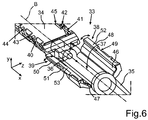
- the injector device 33 includes an injector tube 34, to the front side of which a tapering hollow insertion member 35 joins. This insertion member 35 is provided for introducing through the incision in the eye for inserting the intraocular lens 2 into the eye.
- the injector tube 34 is also formed hollow and a plunger 36 is movable in the injector tube 34 along the longitudinal axis B of the injector tube 34.
- the intraocular lens 2 is pushed out of the injector device 33 through the insertion member 35 by the plunger 36.
- the injector device 33 has a loading chamber 37 in the interior of the injector tube 34.
- the loading chamber 37 is closable by wing-like formed cover flaps 38 and 39. In the representation according to fig. 6 , these cover flaps 38 and 39 are shown in the completely opened position. They can be pivoted in the corresponding directions according to the shown double arrows. By means of the cover flaps 38 and 39, the loading chamber 37 can be closed.
- the cover flaps 38 and 39 are disposed on the injector tube 34 by means of hinges such that they can be pivoted correspondingly.
- curved guide tracks 40 and 41 are formed on opposing sides of the axis B on the injector tube 34.
- further engagement regions 42, 43, 44 and 45 are provided.
- the holding device 1 can be attached to the injector device 33 and in particular to the injector tube 34 and be moved relatively with respect to the injector tube 34.
- the holding device 1 can also be moved relatively to the injector tube 34 without the holding device 1 dropping from the injector tube 34.
- the support member 6 engages these guide tracks 40 and 41 and depending on the displacement position also one or more engagement regions(s) 42 to 45.
- An interior side 46 is formed on the cover flap 38, which is formed unevenly in direction of revolution around the axis B. In corresponding configuration, an interior side 47 is formed on the cover flap 39.
- a guide track 49 is formed at an outside 48 of the cover flap 38.
- a corresponding guide track 51 is formed at an outside 50 of the cover flap 39.
- the cover flap 38 has a free edge o border 52, wherein the cover flap 39 has a free edge or border 53. In the closed state of the cover flaps 38 and 39, preferably, these two edges 52 and 53 are disposed abutting each other.
- the support member 6 is preferably inserted into the guide tracks 40 and 41 on the injector tube 34 with appropriate corresponding engagement members.
- an engagement of members of the support member 6 with one or more of the engagement regions 42 to 45 can also be provided.
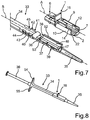
- the entire injector device 33 with the fitted holding device 1 is shown.
- the holding device 1 is positioned on the top of the injector tube 34 and the holding rail 7 is disposed within the loading chamber 37 at least in certain regions.
- the intraocular lens 2 cannot drop from the holding rail 7 in undesired manner and for example cannot fall onto the floor outside of the loading chamber 37.
- the guide tracks 40 and 41 as well as the engagement regions 42 to 45 are formed adjacent to the loading chamber 37 at the outside of the injector tube 34.
- the longitudinal axis A thereof extends parallel to the axis B.
- the holding device 1 After the mechanic coupling to the injector device 33, the holding device 1 is movable along the guide tracks 40 and 41 and therefore, movements along the longitudinal axis B as well as upwards or downwards thereto can be performed.
- a basic position of the holding device 1 is shown, in which it is disposed on the injector device 33.
- the guide members 12 and 14 on the support arms 9 and 10 grip around the cover flaps 38 and 39 on the upper free edges 52 and 53 thereof.
- members of the holding device 1 in particular formed on the support arms 9 and 10 engage the guide tracks 49 and 51 of the cover flaps 38 and 39. It can also be provided that such engagement is only effected upon further movement of the holding device 1 relative to the injector tube 34.
- holding grips 54 and 55 are attached to the injector tube 34, which can be gripped to be able to ensure a counter-pressure upon displacement of the plunger 4.
- FIG. 9 a further perspective representation of a partial section of the injector device 33 with the holding device 1 is shown.
- a displacement from the basic position is shown.
- the holding device 1 is pulled upwards according to the arrow representation P1 in the direction of the axis B. This movement is guided by the guide tracks 40 and 41.
- a user grips the gripping member 16 on the holding device 1 and pulls it back or upwards, respectively, according to the arrow representation P1 in the direction of the axis B.
- the cover flaps 38 and 39 are automatically folded from the completely opened position into a first intermediate closure position on the one hand. Then, it is automatically held by the holding device 1, in particular by the support arms 9 and 10 and the guide members 12 and 14 disposed thereon.
- the path of movement starting from the basic position into the first displacement position of the holding device 1 shown in fig. 9 is for example a few millimeters, in particular about 2 mm.
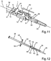
- this is shown in the perspective representation in fig. 12 , in which the injector device 33 is loaded with the intraocular lens 2 in the loading chamber 37, the cover flaps 38 and 39 are completely closed and the holding device 1 is separated from the injector device 33.
- this can also be used in that the cover flaps 38 and 39 are in contact with the support arms 9 and 10 and/or the guide members 12 and 14 and thereby the cover flaps 38 and 39 are kept closed.
- the intraocular lens 2 is already completely rolled up or folded in the loading chamber 37 such that this state is already formed before introduction into the insertion member 7.
- the intraocular lens 2 is no longer directly contacted by the user or even no longer by an additional auxiliary tool such as for example forceps or the like.
- the basic position and the further displacement positions as well as the intermediate closure positions of the cover flaps 38 and 39 associated therewith as well as the final position are haptically perceivable for a user.
- this can be each formed by gentle slide into a smooth locking position.
- the cover flaps 38 and 39 are formed such that they remain self-retaining in the completely closed position shown in fig. 11 and 12 .
- the initial path or the movement path of the holding device 1, respectively, occurs in reverse direction according to the explained initial path and the movement is performed in the direction of the insertion member 7.
- the system is formed such that different configurations of plungers can be used.
- a plurality of different intraocular lenses can be held with the holding device 1 and be loaded into the loading chamber 37.
- the intraocular lenses can be formed differently with regard to their configuration and number of haptic parts. They can be formed as one-piece or multi-piece lenses.
- a holding device 1' ( fig. 14 ) includes a holding rail 7' shown in fig. 13 in perspective representation.
- the holding rail 7' includes gripping members 17' and 18', but which are not disposed at the ends 56 and 57 opposing viewed in longitudinal direction C, but are offset with respect to that.
- the gripping member 17' has two gripping hooks 171' and 172'.
- the gripping member 18' has gripping hooks 181' and 182'.
- the gripping members 17' and 18' do not grip the front edges 58 and 59 of the haptic parts 4 and 5 viewed in longitudinal direction D of the lens 2, but lateral edges 60 and 61 of these haptic parts 4 and 5.
- a receptacle 62 and 63 is formed, respectively.
- these receptacles 62 and 63 are formed open on the front sides of the ends 56 and 57.
- a closed configuration can also be provided.
- Engaging members disposed on the injector tube adjacent to the loading chamber engage with these receptacles 62 and 63 in the assembled state of the holding device 1'. Thereby, the positionally fixed arrangement of the holding rail 7' with the injector tube is then given.
- this holding rail 7' is also formed open to the bottom, and the lens 2 is freely accessible both from below and from the sides.
- a preferred embodiment of a holding device 1' is shown in perspective representation.
- This holding device 1' includes a support member 6' besides the holding rail 7' shown in fig. 13 .
- the support member 6' is formed elongated and designed clamp-like. In the first approximation, the support member 6' can be considered as an inverted Y shape in cross-section.
- the support member 6' has a longitudinal axis E and is also formed open to the bottom.
- the clamp-like structure formed open to the bottom results from the support member 6' having an upper section 64, to which a transition 65 adjoins. At this transition 65, a second lower section 66 forms adjoining, which is wider with respect to the narrower upper section 64.
- the transition 65 is oriented obliquely outwards.
- the support member 6' presents a hollow rail open to the bottom.
- slits 67 and 68 oriented vertically and thus perpendicularly to the longitudinal axis E are formed, which are also formed in pairs on the opposing side.
- the slits 67 and 68 as well as the opposing corresponding slits are continuous and provided for guiding the holding rail 7' upon a vertical movement in y-direction relative to the support member 6'. It can be appreciated that in the basic position or starting position of the holding rail 7', respectively, shown in fig. 14 within the cavity of the support member 6', the gripping members 17' and 18' extend into these slits 67 and 68.
- guide members 12' and 14' Adjoining to the upper section 64, at a front end 69 of the support member 6', guide members 12' and 14' extend downwards. Viewed in z-direction, the guide members 12' and 14' are positioned such that the walls of the lower section 66 are each located further outwards such that a receiving space 71 is formed between a guide member 12' and the adjacent wall 70 of the lower section 66.
- a cover flap for closing the loading chamber can extend into it in the state of the holding device 1' fitted onto the injector tube.
- a free space or a receiving space 73 is also designed between the opposing guide member 14' and an opposing wall 72 of the lower section 66, with which the opposing cover flap can engage correspondingly.
- the guide members 12' and 14' have hook-like holding members 75 or 76, respectively, which are formed for holding and for engaging with a section of an injector tube disposed in between.
- bulges 78 and 79 are formed on opposing sides.
- two such opposing bulges are also formed at analog location at the rear end 74.
- the holding rail 7' is disposed below these bulges 78 and 79 viewed in vertical direction and thus in y-direction and contacted with the top 80 with these bulges 78 and 79.
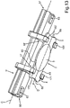
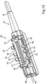
- FIG. 15 a perspective representation of an embodiment of a section 83 of an injector device 33' ( fig. 17 ) is shown.
- the section 83 includes the insertion member 35 and thus the tip, via which the lens 2 is brought into the eye.
- the section 83 includes the loading chamber 37', into which the lens 2 is loaded after removing from the holding rail 7'.
- an injector tube 34' ( fig. 17 ) is thus constructed of two separate parts, which can be detachably assembled and again separated in non-destructive manner.
- a connecting region 84 is formed on the section 83. At this location, a plug connection or a locking connection or a bayonet connection or the like can be provided.
- the piston 36 enters the loading chamber 37' via an opening 85 and then pushes the lens 2 loaded therein outwards through the insertion member 35.
- cover flaps 38' and 39' are shown, wherein the completely opened state is illustrated in this respect.
- plural gripping prongs 90, 91, 92 as well as 93, 94 and 95 formed spaced from each other are each formed.
- the gripping prongs 90 to 92 are formed offset to the gripping prongs 93 to 95.
- the holding device 1' according to the representation in fig. 14 with the lens 2 attached to the holding rail 7' is positionally fixed disposed in the transport container 28 according to the representation in fig. 3 to 5 .
- an entire assembly as is shown in fig. 16 is also disposed in the transport container 28 such that the section 83 is also loaded in the transport container 28 and is transported to the surgeon in this manner. There, by opening the transport container 28, the entire assembly according to fig. 16 can then be removed and be attached to the other section of the injector tube 34'.
- the slits 96 and 97 formed opposing the slits 67 and 68 shown in fig. 14 are also shown.
- the holding device 1' is disposed positionally fixed on the section 83 along the axis B, wherein this is particularly effected by engagement of the engaging members 86, 87 with the receptacles 62 and 63, moreover by gripping around the section 83 at the outside by the guide members 12' and 14', wherein a further rear guide member 98 is also recognizable in fig. 16 .
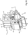
- the injector device 33' is shown in lateral perspective representation. Therein, the section 83 is connected to the remainder of the injector tube at the location 99 such that an entire injector tube 34' again results.
- the support member In loading the lens 2 into the loading chamber 37', only a vertical movement of the support member in the direction of the arrow P (y-direction), but no movement in the direction of the axis B is effected in the shown embodiment.
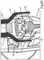
- fig. 18 a sectional representation in the y-z plane in fig. 17 is shown.
- the cover flaps 38' and 39' are illustrated in the completely opened state, and the lens 2 is attached to the holding rail 7'.
- the support member 6' is pressed downwards in the direction of the arrow P. Since the holding rail 7' is positionally fixed attached to the section 83, thus, only a relative movement of the support member 6' to the holding rail 7' and the section 83 is performed.
- the support member 6' is further vertically pressed down such that the cover flaps 38' and 39' are further moved towards each other and are further closed, and thereby the lens 2 is automatically folded.
- the position and the folding state of the lens 2 in fig. 21 are only schematically illustrated, and in practice, this can substantially depart from that as well. With this representation, the automatic folding is only to be indicated symbolically.
- the holding rail 7 is then also disposed above the bulges 78 and 79 and retained there, and thereby, either the support member 6' cannot again fall down readily and simply.
- the lens 2 is also automatically removed from the holding rail 7'.
- Such a plunger will exert greater pressure per unit area on the lens, likely resulting in lens damage.
- the alternative is the use of a soft-tip plunger.
- the problem is that such a plunger cannot easily grasp and positively control the lens when it is unfolded and uncompressed.
- the mechanical closure of the loading chamber of the injector is superior to existing means of manually performing these tasks. It eliminates potential variation and error, and reduces the number of steps and their complexity.
Landscapes
- Health & Medical Sciences (AREA)
- Ophthalmology & Optometry (AREA)
- Cardiology (AREA)
- Oral & Maxillofacial Surgery (AREA)
- Transplantation (AREA)
- Engineering & Computer Science (AREA)
- Biomedical Technology (AREA)
- Heart & Thoracic Surgery (AREA)
- Vascular Medicine (AREA)
- Life Sciences & Earth Sciences (AREA)
- Animal Behavior & Ethology (AREA)
- General Health & Medical Sciences (AREA)
- Public Health (AREA)
- Veterinary Medicine (AREA)
- Prostheses (AREA)
Priority Applications (1)
| Application Number | Priority Date | Filing Date | Title |
|---|---|---|---|
| EP16151305.6A EP3037063B1 (en) | 2009-08-18 | 2010-08-12 | Holding device for an intraocular lens |
Applications Claiming Priority (1)
| Application Number | Priority Date | Filing Date | Title |
|---|---|---|---|
| GB0915098.8A GB2472872B (en) | 2009-08-18 | 2009-08-18 | Holding device for an intraocular lens, packaging and transport means for an intraocular lens and injector device for an intraocular lens. |
Related Child Applications (2)
| Application Number | Title | Priority Date | Filing Date |
|---|---|---|---|
| EP16151305.6A Division-Into EP3037063B1 (en) | 2009-08-18 | 2010-08-12 | Holding device for an intraocular lens |
| EP16151305.6A Division EP3037063B1 (en) | 2009-08-18 | 2010-08-12 | Holding device for an intraocular lens |
Publications (2)
| Publication Number | Publication Date |
|---|---|
| EP2286762A1 EP2286762A1 (en) | 2011-02-23 |
| EP2286762B1 true EP2286762B1 (en) | 2016-08-03 |
Family
ID=41172114
Family Applications (2)
| Application Number | Title | Priority Date | Filing Date |
|---|---|---|---|
| EP10172664.4A Active EP2286762B1 (en) | 2009-08-18 | 2010-08-12 | Holding device for an intraocular lens, packaging and transport means for an intraocular lens, injector device for an intraocular lens as well as method for packaging an intraocular lens and method for loading an intraocular lens into an injector device |
| EP16151305.6A Active EP3037063B1 (en) | 2009-08-18 | 2010-08-12 | Holding device for an intraocular lens |
Family Applications After (1)
| Application Number | Title | Priority Date | Filing Date |
|---|---|---|---|
| EP16151305.6A Active EP3037063B1 (en) | 2009-08-18 | 2010-08-12 | Holding device for an intraocular lens |
Country Status (5)
| Country | Link |
|---|---|
| US (1) | US8597351B2 (enExample) |
| EP (2) | EP2286762B1 (enExample) |
| JP (1) | JP5791247B2 (enExample) |
| ES (1) | ES2623294T3 (enExample) |
| GB (1) | GB2472872B (enExample) |
Families Citing this family (29)
| Publication number | Priority date | Publication date | Assignee | Title |
|---|---|---|---|---|
| US20110166555A1 (en) * | 2009-09-30 | 2011-07-07 | Jianbo Zhou | Carrier for an insertable medical device, insertion tools, methods of use, and kits |
| NL2005182C2 (en) * | 2010-07-30 | 2012-01-31 | Oculentis B V | Intraocular lens injector system. |
| US10478206B2 (en) * | 2011-04-29 | 2019-11-19 | University Of Southern California | Instruments and methods for the implantation of cell-seeded substrates |
| CA2871046C (en) * | 2012-04-20 | 2020-02-25 | Vijay Gulati | Pre-loaded injector for use with intraocular lens |
| CN104379092B (zh) | 2012-06-04 | 2016-12-14 | 爱尔康制药有限公司 | 眼内透镜插入器 |
| CA3078098C (en) | 2012-06-12 | 2022-03-15 | Alcon Inc. | Intraocular gas injector |
| DE102012223885B4 (de) * | 2012-12-20 | 2022-01-05 | Humanoptics Ag | Intraokularlinsen-Aufbewahrungssystem, Übergabe-Anordnung und Verfahren zur Übergabe einer Intraokularlinse an eine Injektions-Einrichtung |
| US9636216B2 (en) * | 2013-04-19 | 2017-05-02 | Staar Surgical Company | Injector cartridge with improved lubricity |
| DE102013105185B4 (de) * | 2013-05-21 | 2017-01-05 | Carl Zeiss Meditec Ag | Kassette zur Aufnahme einer Intraokularlinse, Injektorvorrichtung mit einer Kassette und Verfahren zum Falten einer Intraokularlinse in einer Kassette |
| DE102013105184B4 (de) * | 2013-05-21 | 2020-02-20 | Carl Zeiss Meditec Ag | Injektorvorrichtung zum Einführen einer Intraokularlinse in ein Auge sowie Verfahren zum Falten einer Intraokularlinse in einer Injektorvorrichtung |
| US9795474B2 (en) * | 2013-10-24 | 2017-10-24 | Carl Zeiss Meditec Ag | Hydrophilic IOL packaging system |
| US20150114855A1 (en) * | 2013-10-24 | 2015-04-30 | Aaren Scientific Inc. | Hydrophilic iol packaging system |
| EP3068341B1 (de) * | 2013-11-15 | 2019-08-28 | Medicel AG | Vorrichtung zur aufnahme einer interokularen linse |
| CA2944513C (en) | 2014-04-04 | 2022-07-05 | Jack R. Auld | Intraocular lens inserter |
| KR102249250B1 (ko) | 2014-09-09 | 2021-05-07 | 스타 서지컬 컴퍼니 | 확장된 피사계 심도 및 향상된 원거리 시력의 안과용 임플란트 |
| US12127934B2 (en) | 2014-09-09 | 2024-10-29 | Staar Surgical Company | Method of Providing Modified Monovision to a Subject with a First Lens and a Second Lens |
| US10172706B2 (en) | 2015-10-31 | 2019-01-08 | Novartis Ag | Intraocular lens inserter |
| ES2912080T3 (es) | 2016-03-09 | 2022-05-24 | Staar Surgical Co | Implantes oftálmicos con mayor profundidad de campo y agudeza visual mejorada a distancia |
| US11000367B2 (en) | 2017-01-13 | 2021-05-11 | Alcon Inc. | Intraocular lens injector |
| US12171653B2 (en) | 2017-12-28 | 2024-12-24 | Medicontur Medical Engineering Ltd. | Folding device and injector system for intraocular lenses |
| WO2019130028A1 (en) * | 2017-12-28 | 2019-07-04 | Medicontur Medical Engineering Ltd. | Injector system for intraocular lenses |
| KR102560250B1 (ko) | 2018-08-17 | 2023-07-27 | 스타 서지컬 컴퍼니 | 나노 구배의 굴절률을 나타내는 중합체 조성물 |
| US11224537B2 (en) | 2018-10-19 | 2022-01-18 | Alcon Inc. | Intraocular gas injector |
| ES3014616T3 (en) * | 2018-12-11 | 2025-04-23 | Alcon Inc | Haptic optic management system utilizing a squid clip |
| JP7584499B2 (ja) * | 2019-08-23 | 2024-11-15 | アルコン インコーポレイティド | 眼内レンズカートリッジの取り外し可能なキャップによる作動 |
| US11833032B2 (en) | 2019-08-23 | 2023-12-05 | Alcon Inc. | Retractable cap actuation for an intraocular lens cartridge |
| EP4023191B1 (en) * | 2021-01-05 | 2026-04-29 | Akkolens International B.V. | Combination of lens holder and lens injector cartridge for intraocular lens with multiple optical elements |
| CA3234381A1 (en) | 2021-10-04 | 2023-04-13 | Staar Surgical Company | Ophthalmic implants for correcting vision with a tunable optic, and methods of manufacture and use |
| DE102022109691B3 (de) | 2022-04-21 | 2023-04-27 | Carl Zeiss Meditec Ag | Injektor mit griff zum mitnehmen eines vorderen und eines hinteren verlagerungsmechanismus |
Family Cites Families (32)
| Publication number | Priority date | Publication date | Assignee | Title |
|---|---|---|---|---|
| US4697697A (en) * | 1986-08-18 | 1987-10-06 | Coopervision, Inc. | Method and apparatus for packaging an intraocular lens |
| US5817075A (en) * | 1989-08-14 | 1998-10-06 | Photogenesis, Inc. | Method for preparation and transplantation of planar implants and surgical instrument therefor |
| US6712848B1 (en) * | 1992-09-30 | 2004-03-30 | Staar Surgical Company, Inc. | Deformable intraocular lens injecting apparatus with transverse hinged lens cartridge |
| PT723429E (pt) * | 1992-09-30 | 2002-09-30 | Vladimir Feingold | Sistema de insercao de lentes intra-oculares |
| US5275604A (en) * | 1992-12-03 | 1994-01-04 | Kabi Pharmacia Ophthalmics, Inc. | Contoured duct apparatus and method for insertion of flexible intraocular lens |
| US5468246A (en) * | 1993-07-02 | 1995-11-21 | Iovision, Inc. | Intraocular lens injector |
| US5578042A (en) * | 1994-03-14 | 1996-11-26 | Cumming; J. Stuart | Ophthalmic kit and method for lens insertion |
| EP1338254B1 (en) | 1994-08-05 | 2008-12-03 | Bausch & Lomb Incorporated | A method of packaging an intraocular lens |
| US5643276A (en) | 1995-10-10 | 1997-07-01 | Allergan | Apparatus and method for providing desired rotational orientation to an intraocular lens |
| DE1042999T1 (de) * | 1999-04-08 | 2001-05-23 | Physiol, Angleur | Halter für eine Intraocularlinse |
| US6129733A (en) * | 1999-04-15 | 2000-10-10 | Allergan Sales, Inc. | Apparatus for holding intraocular lenses and injectors, and methods for using same |
| US6386357B1 (en) * | 1999-07-12 | 2002-05-14 | Hoya Healthcare Corporation | Soft intraocular lens-folding device and storage case |
| JP3728155B2 (ja) | 1999-10-05 | 2005-12-21 | キヤノンスター株式会社 | 眼内挿入用レンズの挿入システム |
| SE9904338D0 (sv) | 1999-11-30 | 1999-11-30 | Pharmacia & Upjohn Ab | Intraocular lens implanter |
| DE10015472A1 (de) | 2000-03-29 | 2001-10-11 | Jakob Stehle | Vorrichtung zum Falten und/oder Einrollen einer elastischen Intraokularlinse |
| GB0011507D0 (en) | 2000-05-13 | 2000-06-28 | Duckworth & Kent Ltd | Ophthalmic lens injectors |
| FR2833154B1 (fr) * | 2001-12-12 | 2004-11-19 | Ioltechnologie Production | Cassette et injecteur de lentille intraoculaire souple et procede d'injection de telles lentilles |
| JP2003325569A (ja) * | 2002-05-08 | 2003-11-18 | Canon Star Kk | 眼内挿入用レンズの挿入システム |
| US7014641B2 (en) | 2002-05-08 | 2006-03-21 | Canon-Staar Co., Inc. | Insertion device for intraocular lens |
| US7422604B2 (en) * | 2003-08-28 | 2008-09-09 | Bausch & Lomb Incorporated | Preloaded IOL injector |
| WO2005084588A1 (en) * | 2004-03-02 | 2005-09-15 | Advanced Medical Optics | Devices and methods for storing, loading, and delivering an intraocular lens |
| FR2875125B1 (fr) * | 2004-09-13 | 2006-12-01 | Patrick Meunier | Dispositif de chargement d'une lentille intraoculaire dans une cartouche d'injection |
| JP4766442B2 (ja) * | 2004-12-28 | 2011-09-07 | Hoya株式会社 | 眼内レンズ挿入用器具 |
| US20060142780A1 (en) * | 2004-12-29 | 2006-06-29 | Joel Pynson | Preloaded IOL injector and method |
| US8435289B2 (en) * | 2005-02-11 | 2013-05-07 | Abbott Medical Optics Inc. | Rapid exchange IOL insertion apparatus and methods of using |
| JP4877643B2 (ja) | 2005-12-08 | 2012-02-15 | Hoya株式会社 | 眼内レンズ挿入用器具 |
| US8475526B2 (en) * | 2005-12-22 | 2013-07-02 | Bausch & Lomb Incorporated | Apparatus and methods for loading of an IOL injector |
| EP1972306A4 (en) | 2006-01-13 | 2012-11-28 | Hoya Corp | INSTRUMENT FOR INSERTING INTRAOCULAR LENSES |
| US20080269770A1 (en) * | 2006-12-22 | 2008-10-30 | Joel Pynson | Intraocular Lens Injector Subassembly |
| US20090057167A1 (en) * | 2007-08-30 | 2009-03-05 | Rathert Brian D | Intraocular Lens Packaging |
| JP5086062B2 (ja) | 2007-12-29 | 2012-11-28 | 株式会社ニデック | 眼内レンズ挿入器具 |
| FR2935606B1 (fr) * | 2008-09-11 | 2010-09-03 | Patrick Meunier | Systeme d'injection d'une lentille intraoculaire comprenant un injecteur avec une cartouche et un dispositif de chargement. |
-
2009
- 2009-08-18 GB GB0915098.8A patent/GB2472872B/en active Active
-
2010
- 2010-08-12 EP EP10172664.4A patent/EP2286762B1/en active Active
- 2010-08-12 EP EP16151305.6A patent/EP3037063B1/en active Active
- 2010-08-12 ES ES16151305.6T patent/ES2623294T3/es active Active
- 2010-08-17 JP JP2010182582A patent/JP5791247B2/ja active Active
- 2010-08-17 US US12/858,267 patent/US8597351B2/en active Active
Also Published As
| Publication number | Publication date |
|---|---|
| ES2623294T3 (es) | 2017-07-10 |
| US20110046634A1 (en) | 2011-02-24 |
| GB2472872B (en) | 2014-12-31 |
| HK1153118A1 (en) | 2012-03-23 |
| US8597351B2 (en) | 2013-12-03 |
| JP2011078746A (ja) | 2011-04-21 |
| EP2286762A1 (en) | 2011-02-23 |
| EP3037063B1 (en) | 2017-02-01 |
| GB2472872A (en) | 2011-02-23 |
| GB0915098D0 (en) | 2009-09-30 |
| EP3037063A1 (en) | 2016-06-29 |
| JP5791247B2 (ja) | 2015-10-07 |
Similar Documents
| Publication | Publication Date | Title |
|---|---|---|
| EP2286762B1 (en) | Holding device for an intraocular lens, packaging and transport means for an intraocular lens, injector device for an intraocular lens as well as method for packaging an intraocular lens and method for loading an intraocular lens into an injector device | |
| AU2008276035B2 (en) | Rapid exchange IOL insertion apparatus and methods of using | |
| US9980811B2 (en) | Ocular implant insertion apparatus and methods | |
| EP1173115B1 (en) | Apparatus for holding intraocular lenses and injectors, and methods for using same | |
| EP1720490B1 (en) | Devices for storing, loading, and delivering an intraocular lens | |
| US7458976B2 (en) | Devices and methods for storing, loading, and delivering an intraocular lens | |
| US20250312146A1 (en) | Devices and methods for lens management |
Legal Events
| Date | Code | Title | Description |
|---|---|---|---|
| PUAI | Public reference made under article 153(3) epc to a published international application that has entered the european phase |
Free format text: ORIGINAL CODE: 0009012 |
|
| AK | Designated contracting states |
Kind code of ref document: A1 Designated state(s): AL AT BE BG CH CY CZ DE DK EE ES FI FR GB GR HR HU IE IS IT LI LT LU LV MC MK MT NL NO PL PT RO SE SI SK SM TR |
|
| AX | Request for extension of the european patent |
Extension state: BA ME RS |
|
| RIN1 | Information on inventor provided before grant (corrected) |
Inventor name: RATHERT, BRIAN |
|
| 17P | Request for examination filed |
Effective date: 20110622 |
|
| 17Q | First examination report despatched |
Effective date: 20130703 |
|
| GRAP | Despatch of communication of intention to grant a patent |
Free format text: ORIGINAL CODE: EPIDOSNIGR1 |
|
| RIC1 | Information provided on ipc code assigned before grant |
Ipc: A61F 2/16 20060101AFI20160128BHEP |
|
| INTG | Intention to grant announced |
Effective date: 20160302 |
|
| GRAS | Grant fee paid |
Free format text: ORIGINAL CODE: EPIDOSNIGR3 |
|
| GRAA | (expected) grant |
Free format text: ORIGINAL CODE: 0009210 |
|
| AK | Designated contracting states |
Kind code of ref document: B1 Designated state(s): AL AT BE BG CH CY CZ DE DK EE ES FI FR GB GR HR HU IE IS IT LI LT LU LV MC MK MT NL NO PL PT RO SE SI SK SM TR |
|
| REG | Reference to a national code |
Ref country code: GB Ref legal event code: FG4D |
|
| REG | Reference to a national code |
Ref country code: CH Ref legal event code: EP Ref country code: AT Ref legal event code: REF Ref document number: 816854 Country of ref document: AT Kind code of ref document: T Effective date: 20160815 |
|
| REG | Reference to a national code |
Ref country code: FR Ref legal event code: PLFP Year of fee payment: 7 |
|
| REG | Reference to a national code |
Ref country code: IE Ref legal event code: FG4D |
|
| REG | Reference to a national code |
Ref country code: DE Ref legal event code: R096 Ref document number: 602010035149 Country of ref document: DE |
|
| REG | Reference to a national code |
Ref country code: NL Ref legal event code: MP Effective date: 20160803 |
|
| REG | Reference to a national code |
Ref country code: LT Ref legal event code: MG4D |
|
| REG | Reference to a national code |
Ref country code: AT Ref legal event code: MK05 Ref document number: 816854 Country of ref document: AT Kind code of ref document: T Effective date: 20160803 |
|
| PG25 | Lapsed in a contracting state [announced via postgrant information from national office to epo] |
Ref country code: HR Free format text: LAPSE BECAUSE OF FAILURE TO SUBMIT A TRANSLATION OF THE DESCRIPTION OR TO PAY THE FEE WITHIN THE PRESCRIBED TIME-LIMIT Effective date: 20160803 Ref country code: IS Free format text: LAPSE BECAUSE OF FAILURE TO SUBMIT A TRANSLATION OF THE DESCRIPTION OR TO PAY THE FEE WITHIN THE PRESCRIBED TIME-LIMIT Effective date: 20161203 Ref country code: IT Free format text: LAPSE BECAUSE OF FAILURE TO SUBMIT A TRANSLATION OF THE DESCRIPTION OR TO PAY THE FEE WITHIN THE PRESCRIBED TIME-LIMIT Effective date: 20160803 Ref country code: FI Free format text: LAPSE BECAUSE OF FAILURE TO SUBMIT A TRANSLATION OF THE DESCRIPTION OR TO PAY THE FEE WITHIN THE PRESCRIBED TIME-LIMIT Effective date: 20160803 Ref country code: NO Free format text: LAPSE BECAUSE OF FAILURE TO SUBMIT A TRANSLATION OF THE DESCRIPTION OR TO PAY THE FEE WITHIN THE PRESCRIBED TIME-LIMIT Effective date: 20161103 Ref country code: LT Free format text: LAPSE BECAUSE OF FAILURE TO SUBMIT A TRANSLATION OF THE DESCRIPTION OR TO PAY THE FEE WITHIN THE PRESCRIBED TIME-LIMIT Effective date: 20160803 Ref country code: NL Free format text: LAPSE BECAUSE OF FAILURE TO SUBMIT A TRANSLATION OF THE DESCRIPTION OR TO PAY THE FEE WITHIN THE PRESCRIBED TIME-LIMIT Effective date: 20160803 |
|
| PG25 | Lapsed in a contracting state [announced via postgrant information from national office to epo] |
Ref country code: PL Free format text: LAPSE BECAUSE OF FAILURE TO SUBMIT A TRANSLATION OF THE DESCRIPTION OR TO PAY THE FEE WITHIN THE PRESCRIBED TIME-LIMIT Effective date: 20160803 Ref country code: AT Free format text: LAPSE BECAUSE OF FAILURE TO SUBMIT A TRANSLATION OF THE DESCRIPTION OR TO PAY THE FEE WITHIN THE PRESCRIBED TIME-LIMIT Effective date: 20160803 Ref country code: ES Free format text: LAPSE BECAUSE OF FAILURE TO SUBMIT A TRANSLATION OF THE DESCRIPTION OR TO PAY THE FEE WITHIN THE PRESCRIBED TIME-LIMIT Effective date: 20160803 Ref country code: LV Free format text: LAPSE BECAUSE OF FAILURE TO SUBMIT A TRANSLATION OF THE DESCRIPTION OR TO PAY THE FEE WITHIN THE PRESCRIBED TIME-LIMIT Effective date: 20160803 Ref country code: BE Free format text: LAPSE BECAUSE OF NON-PAYMENT OF DUE FEES Effective date: 20160831 Ref country code: GR Free format text: LAPSE BECAUSE OF FAILURE TO SUBMIT A TRANSLATION OF THE DESCRIPTION OR TO PAY THE FEE WITHIN THE PRESCRIBED TIME-LIMIT Effective date: 20161104 Ref country code: PT Free format text: LAPSE BECAUSE OF FAILURE TO SUBMIT A TRANSLATION OF THE DESCRIPTION OR TO PAY THE FEE WITHIN THE PRESCRIBED TIME-LIMIT Effective date: 20161205 Ref country code: SE Free format text: LAPSE BECAUSE OF FAILURE TO SUBMIT A TRANSLATION OF THE DESCRIPTION OR TO PAY THE FEE WITHIN THE PRESCRIBED TIME-LIMIT Effective date: 20160803 |
|
| REG | Reference to a national code |
Ref country code: CH Ref legal event code: PL |
|
| PG25 | Lapsed in a contracting state [announced via postgrant information from national office to epo] |
Ref country code: EE Free format text: LAPSE BECAUSE OF FAILURE TO SUBMIT A TRANSLATION OF THE DESCRIPTION OR TO PAY THE FEE WITHIN THE PRESCRIBED TIME-LIMIT Effective date: 20160803 Ref country code: CH Free format text: LAPSE BECAUSE OF NON-PAYMENT OF DUE FEES Effective date: 20160831 Ref country code: RO Free format text: LAPSE BECAUSE OF FAILURE TO SUBMIT A TRANSLATION OF THE DESCRIPTION OR TO PAY THE FEE WITHIN THE PRESCRIBED TIME-LIMIT Effective date: 20160803 Ref country code: LI Free format text: LAPSE BECAUSE OF NON-PAYMENT OF DUE FEES Effective date: 20160831 |
|
| REG | Reference to a national code |
Ref country code: DE Ref legal event code: R097 Ref document number: 602010035149 Country of ref document: DE |
|
| PG25 | Lapsed in a contracting state [announced via postgrant information from national office to epo] |
Ref country code: CZ Free format text: LAPSE BECAUSE OF FAILURE TO SUBMIT A TRANSLATION OF THE DESCRIPTION OR TO PAY THE FEE WITHIN THE PRESCRIBED TIME-LIMIT Effective date: 20160803 Ref country code: BG Free format text: LAPSE BECAUSE OF FAILURE TO SUBMIT A TRANSLATION OF THE DESCRIPTION OR TO PAY THE FEE WITHIN THE PRESCRIBED TIME-LIMIT Effective date: 20161103 Ref country code: SM Free format text: LAPSE BECAUSE OF FAILURE TO SUBMIT A TRANSLATION OF THE DESCRIPTION OR TO PAY THE FEE WITHIN THE PRESCRIBED TIME-LIMIT Effective date: 20160803 Ref country code: SK Free format text: LAPSE BECAUSE OF FAILURE TO SUBMIT A TRANSLATION OF THE DESCRIPTION OR TO PAY THE FEE WITHIN THE PRESCRIBED TIME-LIMIT Effective date: 20160803 Ref country code: DK Free format text: LAPSE BECAUSE OF FAILURE TO SUBMIT A TRANSLATION OF THE DESCRIPTION OR TO PAY THE FEE WITHIN THE PRESCRIBED TIME-LIMIT Effective date: 20160803 Ref country code: BE Free format text: LAPSE BECAUSE OF FAILURE TO SUBMIT A TRANSLATION OF THE DESCRIPTION OR TO PAY THE FEE WITHIN THE PRESCRIBED TIME-LIMIT Effective date: 20160803 |
|
| REG | Reference to a national code |
Ref country code: IE Ref legal event code: MM4A |
|
| PLBE | No opposition filed within time limit |
Free format text: ORIGINAL CODE: 0009261 |
|
| STAA | Information on the status of an ep patent application or granted ep patent |
Free format text: STATUS: NO OPPOSITION FILED WITHIN TIME LIMIT |
|
| PG25 | Lapsed in a contracting state [announced via postgrant information from national office to epo] |
Ref country code: MC Free format text: LAPSE BECAUSE OF FAILURE TO SUBMIT A TRANSLATION OF THE DESCRIPTION OR TO PAY THE FEE WITHIN THE PRESCRIBED TIME-LIMIT Effective date: 20160803 |
|
| 26N | No opposition filed |
Effective date: 20170504 |
|
| GBPC | Gb: european patent ceased through non-payment of renewal fee |
Effective date: 20161103 |
|
| PG25 | Lapsed in a contracting state [announced via postgrant information from national office to epo] |
Ref country code: IE Free format text: LAPSE BECAUSE OF NON-PAYMENT OF DUE FEES Effective date: 20160812 |
|
| REG | Reference to a national code |
Ref country code: FR Ref legal event code: PLFP Year of fee payment: 8 |
|
| PG25 | Lapsed in a contracting state [announced via postgrant information from national office to epo] |
Ref country code: SI Free format text: LAPSE BECAUSE OF FAILURE TO SUBMIT A TRANSLATION OF THE DESCRIPTION OR TO PAY THE FEE WITHIN THE PRESCRIBED TIME-LIMIT Effective date: 20160803 Ref country code: LU Free format text: LAPSE BECAUSE OF NON-PAYMENT OF DUE FEES Effective date: 20160812 |
|
| PG25 | Lapsed in a contracting state [announced via postgrant information from national office to epo] |
Ref country code: GB Free format text: LAPSE BECAUSE OF NON-PAYMENT OF DUE FEES Effective date: 20161103 |
|
| PG25 | Lapsed in a contracting state [announced via postgrant information from national office to epo] |
Ref country code: HU Free format text: LAPSE BECAUSE OF FAILURE TO SUBMIT A TRANSLATION OF THE DESCRIPTION OR TO PAY THE FEE WITHIN THE PRESCRIBED TIME-LIMIT; INVALID AB INITIO Effective date: 20100812 Ref country code: CY Free format text: LAPSE BECAUSE OF FAILURE TO SUBMIT A TRANSLATION OF THE DESCRIPTION OR TO PAY THE FEE WITHIN THE PRESCRIBED TIME-LIMIT Effective date: 20160803 |
|
| PG25 | Lapsed in a contracting state [announced via postgrant information from national office to epo] |
Ref country code: TR Free format text: LAPSE BECAUSE OF FAILURE TO SUBMIT A TRANSLATION OF THE DESCRIPTION OR TO PAY THE FEE WITHIN THE PRESCRIBED TIME-LIMIT Effective date: 20160803 Ref country code: MT Free format text: LAPSE BECAUSE OF NON-PAYMENT OF DUE FEES Effective date: 20160831 Ref country code: MK Free format text: LAPSE BECAUSE OF FAILURE TO SUBMIT A TRANSLATION OF THE DESCRIPTION OR TO PAY THE FEE WITHIN THE PRESCRIBED TIME-LIMIT Effective date: 20160803 |
|
| REG | Reference to a national code |
Ref country code: FR Ref legal event code: PLFP Year of fee payment: 9 |
|
| PG25 | Lapsed in a contracting state [announced via postgrant information from national office to epo] |
Ref country code: AL Free format text: LAPSE BECAUSE OF FAILURE TO SUBMIT A TRANSLATION OF THE DESCRIPTION OR TO PAY THE FEE WITHIN THE PRESCRIBED TIME-LIMIT Effective date: 20160803 |
|
| P01 | Opt-out of the competence of the unified patent court (upc) registered |
Effective date: 20230530 |
|
| PGFP | Annual fee paid to national office [announced via postgrant information from national office to epo] |
Ref country code: DE Payment date: 20250820 Year of fee payment: 16 |
|
| PGFP | Annual fee paid to national office [announced via postgrant information from national office to epo] |
Ref country code: FR Payment date: 20250829 Year of fee payment: 16 |