EP2284475A2 - Kombinierter Scharnier- Verschluss, insbesondere bei Schutzhüllen oder Verpackungen - Google Patents
Kombinierter Scharnier- Verschluss, insbesondere bei Schutzhüllen oder Verpackungen Download PDFInfo
- Publication number
- EP2284475A2 EP2284475A2 EP20100008055 EP10008055A EP2284475A2 EP 2284475 A2 EP2284475 A2 EP 2284475A2 EP 20100008055 EP20100008055 EP 20100008055 EP 10008055 A EP10008055 A EP 10008055A EP 2284475 A2 EP2284475 A2 EP 2284475A2
- Authority
- EP
- European Patent Office
- Prior art keywords
- protective cover
- closure
- fabric
- parts
- shaped
- Prior art date
- Legal status (The legal status is an assumption and is not a legal conclusion. Google has not performed a legal analysis and makes no representation as to the accuracy of the status listed.)
- Granted
Links
Images

Classifications
-
- F—MECHANICAL ENGINEERING; LIGHTING; HEATING; WEAPONS; BLASTING
- F42—AMMUNITION; BLASTING
- F42B—EXPLOSIVE CHARGES, e.g. FOR BLASTING, FIREWORKS, AMMUNITION
- F42B39/00—Packaging or storage of ammunition or explosive charges; Safety features thereof; Cartridge belts or bags
- F42B39/26—Packages or containers for a plurality of ammunition, e.g. cartridges
-
- F—MECHANICAL ENGINEERING; LIGHTING; HEATING; WEAPONS; BLASTING
- F42—AMMUNITION; BLASTING
- F42B—EXPLOSIVE CHARGES, e.g. FOR BLASTING, FIREWORKS, AMMUNITION
- F42B30/00—Projectiles or missiles, not otherwise provided for, characterised by the ammunition class or type, e.g. by the launching apparatus or weapon used
- F42B30/08—Ordnance projectiles or missiles, e.g. shells
- F42B30/10—Mortar projectiles
- F42B30/12—Mortar projectiles with provision for additional propulsive charges, or for varying the length
-
- F—MECHANICAL ENGINEERING; LIGHTING; HEATING; WEAPONS; BLASTING
- F42—AMMUNITION; BLASTING
- F42B—EXPLOSIVE CHARGES, e.g. FOR BLASTING, FIREWORKS, AMMUNITION
- F42B39/00—Packaging or storage of ammunition or explosive charges; Safety features thereof; Cartridge belts or bags
- F42B39/22—Locking of ammunition in transport containers
-
- F—MECHANICAL ENGINEERING; LIGHTING; HEATING; WEAPONS; BLASTING
- F42—AMMUNITION; BLASTING
- F42B—EXPLOSIVE CHARGES, e.g. FOR BLASTING, FIREWORKS, AMMUNITION
- F42B5/00—Cartridge ammunition, e.g. separately-loaded propellant charges
- F42B5/38—Separately-loaded propellant charges, e.g. cartridge bags
Definitions
- the invention relates to a combined hinge closure on packaging, protective covers or sheaths of scientific and medical instruments, tools, to packages, etc., but in particular for protective covers for arranged on a Leitwerkschaft a mortar shell propellant charges.
- the propellant charges for example, as slotted rings around the rear of the projectile body subsequent Leitwerkschaft are placed.
- the often mechanically and temperature-sensitive propellant charges are protected by an additional protective casing enclosing the propellant charges (also within the packaging of the ammunition).
- the mostly multi-part, for example made of plastic protective sleeves are held together by hinges, clamps or even by the protective sleeves wrap around adhesive or Velcro.
- a disadvantage of the known protective covers is in particular that the removal of the protective sleeves is relatively time-consuming, either because the Velcro or adhesive tapes unwound or more brackets must be solved, the ammunition usually has to be rotated about its longitudinal axis, so for losing weight the protective cover is needed for several seconds. In addition, a lot of space is usually required to remove the protective cover elements.
- a propellant charge container which is arranged to protect the horseshoe-shaped on the Leitwerkschaft a mortar shell formed propellant charge body against damage and environmental influences, the propellant charge bodies each having a central opening and a transition into the central opening radial slot for pushing the propellant charge body on the shank of the grenade.
- the closure of the protective container has a first closure part, which has a central region which bridges the radial slots of the propellant charge bodies and extends in the circumferential direction within the radial slots, so that the propellant charge bodies within the propellant charge protection container have a predefined position.
- At least one handle is attached to the first closure part, by means of which the first closure part for opening the propellant charge protection container can be pulled outwards and the propellant charge protection container can be removed.
- the connection of the two closure parts to be released can be, for example, a hook-and-loop fastener.
- the invention has for its object to provide a protective cover for measuring instruments or the like, for propellant charges, in particular for mortar shells, or other to be wrapped or protective assemblies, which can be removed manually and in no time.
- the invention is based essentially on the idea of carrying out a hinge used for connecting at least two parts in practice as a combined hinge closure.
- the protective cover, packaging, wrapping, etc. which consists of at least two cup-shaped parts and are designed such that they enclose the assemblies, such as measuring instruments, propellant charges, etc., on the outside, substantially form-fitting with their intended use with at least provided with such a hinge closure.
- each of the two shell-shaped parts on the outside in the upper and lower end portions of its first side edge is firmly connected to a fabric band, so that there is a well tangible loop-shaped fabric band area between the upper and lower end portions.
- the two shell-shaped parts have outside in the upper and lower end portions their second side edges each have an area on which a first closure element of a positive connection, such as a hook-and-loop fastener, is attached.
- the respective fabric band at least in a region adjoining its attachment region, has a second closure element of the positive connection which forms the positive connection with the first closure element, so that the protective cover can be fixed in its intended position.
- the shell-shaped parts may preferably be made of plastic, since such parts can be produced inexpensively.
- Alternative materials such as metal, aluminum or cardboard are also conceivable.
- the two fabric bands may be velcro, velor or mushroom bands, so that separate Velcro areas on the fabric bands can be omitted.
- the first closure element can be, for example, hook or mushroom strip sections. It has been found that a higher strength of the closure is achieved when a fleece and a mushroom head are combined.
- chain, band-shaped or rope-shaped parts can be used with positive connections as a combined hinge closure.
- the areas where the Cloth tapes attached to the cup-shaped parts and / or on which the second closure elements of the hook and loop fasteners are arranged, are formed tab-shaped.
- the cup-shaped parts can have on their outside additional Velcro areas, which fix the provided with corresponding Velcro fabric bands.
- the two parts 2, 3 each have side flaps 4-7 and 4'-7 'in the two upper and in the two lower end regions of the side edges 8, 9 and 8', 9 '. It is connected to the corresponding side flaps 4, 5 and 4 ', 5' of the respective first side edge 8, 8 'of the two shell-shaped parts 2, 3, the one end of a looped fabric tape 10, 11, so that between the upper and lower End regions a loop-shaped fabric tape portion 12, 13 results.
- the respective loop tape 10, 11 in an area adjacent to its attachment region (ie in the region of the tabs 4, 5 and 4, 5 ') with the hook tape sections 14', 15 'and 14, 15 of the respective adjacent cup-shaped part 2, 3 connected to a hook and loop fastener, so that the two shell-shaped parts 2, 3 (and thus also the protective cover) are fixed in a proper position.
- Fig.1 the protective cover 1 is shown in its open position, so that only the loop tape 11, which is attached to the side flaps 4 ', 5' of the cup-shaped part 3, forms a Velcro connection with the hook tape sections 14, 15 of the cup-shaped part 2. This results for the two shell-shaped parts 2, 3 caused by the loop tape 11 hinge connection.
- Velcro strips 10, 11 are connected to arranged on the outside of the cup-shaped parts additional Velcro areas 16, 16 'and thus held in a defined position.
- the respectively more conveniently located loop tape 10, 11 is grasped and pulled vigorously. As a result, the loop tape 10, 11 is released from its associated side hook tape sections 14 ', 15' or 14, 15 and the protective cover 1 is opened again.
- the other fabric band then serves as a hinge ( Fig.1 ), so that the two shell-shaped parts 2, 3 do not fall apart and can also be easily reassembled.
- Fig. 3 shows a further embodiment of the protective cover 1. This differs from that of Fig. 1 in particular in that a fastening 17 is clamped or sewn, for example, on the hook-and-loop tape section 14 'or 15', through which Flauschb S 10, 11 are connected to the cup-shaped parts 2, 3.
- the invention is of course not limited to the illustrated embodiment.
- the protective cover can be composed of more than two shell-shaped segments instead of two half shells, so that a corresponding number of hinge closures is required.
- the protective cover can also be provided in other applications, such as, for example, as protective cover for measuring instruments (scientific, medical, mining, etc.).
- the protective cover can also act as packaging in these cases. If it concerns angular assemblies (100), then the inner contour of the protective cover must be selected accordingly.
- the combined hinge closure can of course also be used on parcels, wherein the protective cover is formed by the package parts.
Landscapes
- Engineering & Computer Science (AREA)
- General Engineering & Computer Science (AREA)
- Chemical & Material Sciences (AREA)
- Combustion & Propulsion (AREA)
- Packaging Of Annular Or Rod-Shaped Articles, Wearing Apparel, Cassettes, Or The Like (AREA)
- Wrappers (AREA)
- Packages (AREA)
Abstract
Description
- Die Erfindung betrifft einen kombinierten Scharnier-Verschluss an Verpackungen, Schutzhüllen oder Umhüllungen wissenschaftlicher sowie medizinischer Instrumente, Werkzeuge, an Paketen etc., insbesondere aber bei Schutzhüllen für an einem Leitwerkschaft einer Mörsergranate angeordnete Treibladungen.
- Bei Mörsergranaten sind die Treibladungen beispielsweise als geschlitzte Ringe um den sich an den Geschoßkörper heckseitigen anschließenden Leitwerkschaft gelegt. Bei der Lagerung und dem Transport der Mörsergranaten werden die oft mechanisch- und temperaturempfindlichen Treibladungen durch eine zusätzliche, die Treibladungen umschließende Schutzhülle (auch innerhalb der Verpackung der Munition) geschützt.
- Die meist mehrteiligen, beispielsweise aus Kunststoff bestehenden Schutzhüllen werden durch Scharniere, Klammern oder auch durch die Schutzhüllen umschlingenden Klebe-oder Klettbänder zusammengehalten.
- Nachteilig bei den bekannten Schutzhüllen ist insbesondere, dass das Abnehmen der Schutzhüllen relativ zeitaufwendig ist, weil entweder die Klett- bzw. Klebebänder abgewickelt oder mehrere Klammern gelöst werden müssen, wobei die Munition in der Regel um ihre Längsachse gedreht werden muss, sodass für das Abnehmen der Schutzhülle mehrere Sekunden benötigt wird. Außerdem wird üblicherweise viel Freiraum zum Abnehmen der Schutzhüllenelemente benötigt.
- In der
DE 10 2007 050 981 B3 wird ein Treibladungsschutzbehälter beschrieben, der zum Schutz der auf dem Leitwerkschaft einer Mörsergranate angeordneten, hufeisenförmig ausgebildeten Treibladungskörper gegen Beschädigungen und Umwelteinflüsse dient, wobei die Treibladungskörper jeweils eine zentrale Öffnung sowie einen in die zentrale Öffnung übergehenden radialen Schlitz zum Aufschieben der Treibladungskörper auf den Schaft der Granate aufweisen. Der Verschluss des Schutzbehälters weist dabei ein erstes Verschlussteil auf, welches einen die radialen Schlitze der Treibladungskörper überbrückenden mittleren Bereich besitzt, der sich innerhalb der radialen Schlitze in Umfangsrichtung erstreckt, sodass die Treibladungskörper innerhalb des Treibladungsschutzbehälters eine vordefinierte Lage aufweisen. Außerdem ist an dem ersten Verschlussteil mindestens ein Griffstück befestigt, mittels dessen das erste Verschlussteil zum Öffnen des Treibladungsschutzbehälters nach außen gezogen und der Treibladungsschutzbehälter entfernt werden kann. Die zu lösende Verbindung der beiden Verschlussteile kann dabei beispielsweise ein Klettverschluss sein. - Der Erfindung liegt die Aufgabe zugrunde, eine Schutzhülle für Messinstrumente oder dergleichen, für Treibladungen, insbesondere für Mörsergranaten, oder andere zu umhüllende bzw. schützenden Baugruppen anzugeben, die manuell und in kürzester Zeit entfernt werden kann.
- Diese Aufgabe wird erfindungsgemäß durch die Merkmale des Anspruchs 1 bzw. 5 gelöst. Weitere, besonders vorteilhafte Ausgestaltungen der Erfindung offenbaren die Unteransprüche.
- Die Erfindung beruht im Wesentlichen auf dem Gedanken, ein zum Verbinden von wenigstens zwei Teilen in der Praxis verwendetes Scharnier als kombinierten Scharnier-Verschluss auszuführen.
- In Weiterführung der Idee wird die Schutzhülle, Verpackung, Umhüllung etc., die aus mindestens zwei schalenförmigen Teilen besteht und derart ausgebildet sind, dass sie bei ihrer bestimmungsgemäßen Verwendung die Baugruppen, wie Messinstrumente, Treibladungen etc., außenseitig, im Wesentlichen formschlüssig umschließen mit wenigstens einem derartigen Scharnier-Verschluss versehen. Dabei ist jedes der beiden schalenförmigen Teile außenseitig in den oberen und unteren Endbereichen seines ersten Seitenrandes fest mit einem Gewebeband verbunden, sodass sich zwischen den oberen und unteren Endbereichen ein gut greifbarer schlaufenförmiger Gewebebandbereich ergibt. Die beiden schalenförmigen Teile weisen außenseitig in den oberen und unteren Endbereichen ihrer zweiten Seitenränder jeweils einen Bereich auf, an dem ein erstes Verschlusselement einer formschlüssigen Verbindung, wie die eines Klettverschlusses, befestigt ist. Außerdem weist das jeweilige Gewebeband mindestens in einem sich an seinen Befestigungsbereich anschließenden Bereich ein zweites Verschlusselement der formschlüssigen Verbindung auf, das mit dem ersten Verschlusselement zusammen die formschlüssige Verbindung bildet, sodass die Schutzhülle in ihrer bestimmungsgemäßen Lage fixierbar ist.
- Durch die Verwendung einer derartigen Schutzhülle mit mehrteiliger Gewebebandanordnung mit Klettverschlusswirkung wird erreicht, dass das Gewebeband sowohl die Funktion eines Verschlusses als auch eines Scharniers übernehmen kann.
- Zum Öffnen der Schutzhülle braucht lediglich eines der beiden schlaufenförmigen Gewebebandbereiche gegriffen und kräftig gezogen werden. Dadurch lösen sich die diesem Gewebeband zugeordneten seitlichen Verschlusselemente und die Schutzhülle wird geöffnet. Das zweite Gewebeband dient dann als Scharnier, sodass die beiden Hüllenteile nicht auseinanderfallen und einfach wieder zusammengesetzt werden können. Bei praktischen Ausführungsbeispielen der Erfindung dauerte der gesamte, mit dem Öffnen und Abnehmen der Schutzhüllen verbundene Vorgang weniger als 1 Sekunde.
- Die schalenförmig ausgebildeten Teile können vorzugsweise aus Kunststoff bestehen, da sich derartige Teile kostengünstig herstellen lassen. Alternative Werkstoffe wie Metall, Aluminium oder Pappe sind ebenfalls denkbar.
- Bei den beiden Gewebebändern kann es sich um Flausch-, Velour- oder Pilzbänder handeln, sodass separate Klettbandbereiche an den Gewebebändern entfallen können.
- Bei dem ersten Verschlusselement kann es sich beispielsweise um Haken- oder Pilzbandabschnitte handeln. Es hat sich gezeigt, dass eine höhere Festigkeit des Verschlusses erreicht wird, wenn ein Flausch und ein Pilzkopf miteinander kombiniert werden.
- Alternativ sind auch Ketten-, bandförmige bzw. seilförmige Teile mit formschlüssigen Verbindungen als kombinierter Scharnier-Verschluss einsetzbar.
- Bei einer Ausführungsform der Erfindung ist vorgesehen, dass die Bereiche, an denen die Gewebebänder an den schalenförmigen Teilen befestigt und/oder an denen die zweiten Verschlusselemente der Klettverschlüsse angeordnet sind, laschenförmig ausgebildet sind.
- Damit bei geschlossener Schutzhülle die Gewebebänder in einer definierten Ruhelage gehalten werden, können die schalenförmigen Teile auf ihrer Außenseite zusätzliche Klettbereiche aufweisen, welche die mit entsprechenden Klettbereichen versehenen Gewebebänder fixieren.
- Weitere Einzelheiten und Vorteile der Erfindung ergeben sich aus den folgenden, anhand von Figuren erläuterten Ausführungsbeispielen.
- Es zeigen:
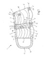
- Fig.1
- eine erfindungsgemäße Schutzhülle in ihrer geöffneten Position und
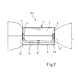
- Fig.2
- schematisch die Seitenansicht der in
Fig.1 dargestellten Schutzhülle in ihrer ge- schlossenen Position, bei der sie die Treibladungen einer Mörsergranate um- schließt, - Fig. 3
- eine weitere Variante der Schutzhülle in ihrer geöffneten Position.
- Die beiden Teile 2, 3 weisen jeweils Seitenlaschen 4-7 und 4'-7' in den beiden oberen und in den beiden unteren Endbereichen der Seitenränder 8, 9 und 8', 9' auf. Dabei ist mit den entsprechenden Seitenlaschen 4, 5 und 4', 5' des jeweils ersten Seitenrandes 8, 8' der beiden schalenförmigen Teile 2, 3 das eine Ende eines als Flauschband ausgebildeten Gewebebandes 10, 11 verbunden, sodass sich zwischen den oberen und unteren Endbereichen ein schlaufenförmiger Gewebebandbereich 12, 13 ergibt.
- An den beiden Seitenlaschen 6, 7 und 6', 7' der zweiten Seitenränder 9, 9' der schalenförmigen Teile 2, 3 sind auf der Rückseite jeweils Hakenbandabschnitte 14, 15 und 14', 15' befestigt, die mit den Flauschbändern 10, 11 zusammenwirken.
- Hierzu wird das jeweilige Flauschband 10, 11 in einem sich an seinen Befestigungsbereich (d.h. im Bereich der Laschen 4, 5 und 4, 5') anschließenden Bereich mit den Hakenbandabschnitten 14', 15' und 14, 15 des jeweils benachbarten schalenförmigen Teiles 2, 3 zu einem Klettverschluss verbunden, sodass die beiden schalenförmigen Teile 2, 3 (und damit auch die Schutzhülle) in einer bestimmungsgemäßen Lage fixiert werden.
- In
Fig.1 ist die Schutzhülle 1 in ihrer geöffneten Position dargestellt, sodass lediglich das Flauschband 11, welches an den Seitenlaschen 4', 5' des schalenförmigen Teiles 3 befestigt ist, mit den Hakenbandabschnitten 14, 15 des schalenförmigen Teiles 2 eine Klettverschlussverbindung bildet. Dadurch ergibt sich für die beiden schalenförmigen Teile 2, 3 eine durch das Flauschband 11 bewirkte Scharnierverbindung. - Sollen entsprechende Treibladungen der Mörsergranate 100 geschützt werden, so werden die beiden schalenförmigen Teile 2, 3 um die Treibladungen herumgeklappt und auch das Flauschband 10 mit den Hakenbandabschnitten 14', 15' zu einem Klettverschluss verbunden (
Fig.2 ). - Abschließend werden die Flauschbänder 10, 11 mit auf der Außenseite der schalenförmigen Teile angeordneten zusätzlichen Klettbandbereichen 16, 16' verbunden und damit in einer definierten Lage gehalten.
- Zum Öffnen der Schutzhülle 1 wird das jeweils günstiger gelegene Flauschband 10, 11 gegriffen und kräftig gezogen. Dadurch löst sich das Flauschband 10, 11 von den ihm zugeordneten seitlichen Hakenbandabschnitten 14', 15' oder 14, 15 und die Schutzhülle 1 wird wieder geöffnet. Das jeweils andere Gewebeband dient dann als Scharnier (
Fig.1 ), sodass die beiden schalenförmigen Teile 2, 3 nicht auseinanderfallen und auch einfach wieder zusammengesetzt werden können. -
Fig. 3 zeigt eine weitere Ausführung der Schutzhülle 1. Diese unterscheidet sich gegenüber der ausFig. 1 insbesondere dadurch, dass eine Befestigung 17 beispielsweise geklammert oder genäht am Hakenbandabschnitt 14' bzw. 15' vorgesehen ist, durch die Flauschbänder 10, 11 mit den schalenförmigen Teilen 2, 3 verbunden sind. - Die Erfindung ist selbstverständlich nicht auf das dargestellte Ausführungsbeispiel beschränkt. So können statt Klettbänder in gleicher Weise auch selbstklebende Klebebänder, Ketten-, bandförmige bzw. seilförmige Teile mit formschlüssigen Verbindungen verwendet werden. Die Schutzhülle kann statt aus zwei Halbschalen auch aus mehr als zwei schalenförmigen Segmenten zusammensetzbar sein, sodass eine entsprechende Anzahl von Scharnier-Verschlüssen erforderlich ist. Des Weiteren kann, wie bereits ausgeführt, die Schutzhülle auch bei anderen Einsätzen vorgesehen werden, wie beispielsweise als Schutzhülle für Messinstrumente (wissenschaftlich, medizinisch, Bergbau etc.). Die Schutzhülle kann in diesen Fällen auch als Verpackung fungieren. Handelt es sich um kantige Baugruppen (100), so ist die Innenkontur der Schutzhülle entsprechend zu wählen. Der kombinierte Scharnier- Verschluss kann selbstverständlich auch an Paketen eingesetzt werden, wobei die Schutzhülle dabei durch die Paketteile gebildet wird.
-
- 1
- Schutzhülle
- 2,3
- schalenförmige Teile
- 4-7
- Seitenlaschen
- 4'-7'
- Seitenlaschen
- 8,8'
- (erste) Seitenränder
- 9,9'
- (zweite) Seitenränder
- 10,11
- Gewebebänder, Flauschbänder
- 12,13
- Gewebebandbereiche
- 14,15
- Hakenbandabschnitte, erste Verschlusselemente
- 14',15'
- Hakenbandabschnitte, erste Verschlusselemente
- 16,16'
- Klettbandbereiche
- 17
- Befestigung
- 20
- kombinierter Scharnier-Verschluss
- 21
- kombinierter Scharnier-Verschluss
- 100
- Mörsergranate
Claims (11)
- Kombinierter Scharnier-Verschluss (20, 21), zum Verbinden von wenigstens zwei Teilen (2, 3) bestehend aus- einem Gewebeband (10, 11), das derart gelegt wird, dass sich zwischen einem oberen und einem unteren Endbereich ein schlaufenförmiger Gewebebandbereich (12, 13) ergibt,- mit Seitenlaschen (4-7, 4'-7'), wobei- im oberen und unteren Endbereichen der zweiten Seitenlaschen (6, 7, 6', 7') jeweils ein Bereich eingebunden ist, an dem ein erstes Verschlusselement (14, 14', 15, 15') einer formschlüssigen Verbindung befestigt ist und- das jeweilige Gewebeband (10, 11) mindestens in einem sich an seinen Befestigungsbereich anschließenden Bereich ein zweites Verschlusselement der formschlüssigen Verbindung aufweist, das mit dem ersten Verschlusselement (14, 14', 15, 15') zusammen die formschlüssige Verbindung bildet.
- Verschluss nach Anspruch 1, dadurch gekennzeichnet, dass die formschlüssige Verbindung durch ein Klettband, ein Ketten-, band -bzw. seilförmiges Teil gebildet werden kann.
- Verschluss nach Anspruch 1 oder 2, dadurch gekennzeichnet, dass es sich bei den beiden Gewebebändern (10, 11) um Flausch-, Velour- oder Pilzbänder handelt.
- Verschluss nach einem der Ansprüche 1 bis 3, dadurch gekennzeichnet, dass es sich bei dem ersten Verschlusselement (14, 14', 15, 15') um ein Haken- oder Pilzbandabschnitt handelt.
- Schutzhülle (1) oder Verpackung für Baugruppen (100) mit dem Scharnier-Verschluss (29, 21) nach einem der Ansprüche 1 bis 4, mit den Merkmalen:- die Schutzhülle (1) besteht aus mindestens zwei Teilen (2, 3), welche derart ausgebildet sind, dass sie bei ihrer bestimmungsgemäßen Verwendung die Baugruppe (100) außenseitig im Wesentlichen formschlüssig umschließen;- jedes der beiden Teile (2, 3) ist außenseitig in den oberen und unteren Endbereichen seines ersten Seitenrandes (8, 8') fest mit einem Gewebeband (10, 11) verbunden, sodass sich zwischen den oberen und unteren Endbereichen der schlaufenförmiger Gewebebandbereich (12, 13) ergibt;- die beiden Teile (2, 3) weisen außenseitig in den oberen und unteren Endbereichen ihrer zweiten Seitenränder (9, 9') jeweils einen Bereich auf, an dem ein erstes Verschlusselement (14, 14', 15, 15') der formschlüssigen Verbindung befestigt ist;- das jeweilige Gewebeband (10, 11) weist mindestens in dem sich an seinen Befestigungsbereich anschließenden Bereich ein zweites Verschlusselement der formschlüssigen Verbindung auf, das mit dem ersten Verschlusselement (14, 14', 15, 15') zusammen die formschlüssige Verbindung bildet, sodass die Schutzhülle (1) in ihrer bestimmungsgemäßen Lage fixierbar ist.
- Schutzhülle nach Anspruch 5, dadurch gekennzeichnet, dass die schalenförmig ausgebildeten Teile (2, 3) aus Kunststoff, Metall oder Pappe bestehen.
- Schutzhülle nach Anspruch 5 oder 6, dadurch gekennzeichnet, dass die Bereiche, an denen die Gewebebänder (10, 11) an den schalenförmigen Teilen (2, 3) befestigt und/oder an denen die ersten Verschlusselemente (14, 14', 15, 15') der Klettverschlüsse angeordnet sind, laschenförmig ausgebildet sind.
- Schutzhülle nach einem der Ansprüche 5 bis 7, dadurch gekennzeichnet, dass die schalenförmigen Teile (2, 3) auf ihrer Außenseite zusätzliche Klettbandbereiche (16, 16') aufweisen, welche die Gewebebänder (10, 11) in einer definierten Lage halten.
- Schutzhülle nach einem der Ansprüche 5 bis 8, dadurch gekennzeichnet, dass zwei oder mehr Verschlusselemente derart verbunden sind, dass sie mit einer Handbewegung gelöst werden können.
- Schutzhülle nach einem der Ansprüche 5 bis 9, dadurch gekennzeichnet, dass die Baugruppen (100) Messinstrumente, Werkzeuge oder dergleichen sein können.
- Schutzhülle nach einem der Ansprüche 5 bis 10, dadurch gekennzeichnet, dass die Baugruppen (100) Treibladungen insbesondere einer Mösergranate sind.
Applications Claiming Priority (1)
| Application Number | Priority Date | Filing Date | Title |
|---|---|---|---|
| DE200910037351 DE102009037351A1 (de) | 2009-08-14 | 2009-08-14 | Kombinierter Scharnier-Verschluss, insbesondere bei Schutzhüllen oder Verpackungen |
Publications (3)
| Publication Number | Publication Date |
|---|---|
| EP2284475A2 true EP2284475A2 (de) | 2011-02-16 |
| EP2284475A3 EP2284475A3 (de) | 2014-04-09 |
| EP2284475B1 EP2284475B1 (de) | 2015-10-21 |
Family
ID=43064491
Family Applications (1)
| Application Number | Title | Priority Date | Filing Date |
|---|---|---|---|
| EP10008055.5A Active EP2284475B1 (de) | 2009-08-14 | 2010-08-02 | Kombinierter Scharnier-Verschluss, insbesondere bei Schutzhüllen oder Verpackungen |
Country Status (3)
| Country | Link |
|---|---|
| EP (1) | EP2284475B1 (de) |
| DE (1) | DE102009037351A1 (de) |
| ES (1) | ES2556956T3 (de) |
Families Citing this family (1)
| Publication number | Priority date | Publication date | Assignee | Title |
|---|---|---|---|---|
| DE102011050282B3 (de) * | 2011-05-11 | 2012-09-13 | Krauss-Maffei Wegmann Gmbh & Co. Kg | Vorrichtung und Verfahren zum Portionieren einer Treibladung |
Citations (1)
| Publication number | Priority date | Publication date | Assignee | Title |
|---|---|---|---|---|
| DE102007050981B3 (de) | 2007-10-25 | 2009-01-02 | Rheinmetall Landsysteme Gmbh | Treibladungsschutzbehälter |
Family Cites Families (5)
| Publication number | Priority date | Publication date | Assignee | Title |
|---|---|---|---|---|
| DE4311222A1 (de) * | 1993-04-05 | 1994-10-06 | Hans Prof Roericht | Behälter zur Aufnahme von Gegenständen |
| US6837164B1 (en) * | 2002-11-13 | 2005-01-04 | The United States Of America As Represented By The Secretary Of The Army | Propelling charge increment protector for 120mm mortar ammunition |
| US7059251B1 (en) * | 2004-09-09 | 2006-06-13 | The United States Of America As Represented By The Secretary Of The Army | Propelling charge support for a mortar cartridge |
| DE202006000568U1 (de) * | 2006-01-16 | 2006-03-09 | Liaw, Charlie | Aufbewahrungseinrichtung mit beliebiger Benutzungsweise |
| FI121321B (fi) * | 2008-01-21 | 2010-09-30 | Patria Land & Armament Oy | Menetelmä lisäpanosten kiinnittämiseksi kranaatinheittimen ammukseen, ammus sekä lisäpanosjärjestelmä |
-
2009
- 2009-08-14 DE DE200910037351 patent/DE102009037351A1/de not_active Withdrawn
-
2010
- 2010-08-02 EP EP10008055.5A patent/EP2284475B1/de active Active
- 2010-08-02 ES ES10008055.5T patent/ES2556956T3/es active Active
Patent Citations (1)
| Publication number | Priority date | Publication date | Assignee | Title |
|---|---|---|---|---|
| DE102007050981B3 (de) | 2007-10-25 | 2009-01-02 | Rheinmetall Landsysteme Gmbh | Treibladungsschutzbehälter |
Also Published As
| Publication number | Publication date |
|---|---|
| EP2284475B1 (de) | 2015-10-21 |
| EP2284475A3 (de) | 2014-04-09 |
| DE102009037351A1 (de) | 2011-02-17 |
| ES2556956T3 (es) | 2016-01-21 |
Similar Documents
| Publication | Publication Date | Title |
|---|---|---|
| DE2849680C2 (de) | Vorratsbehälter für eine Heftpflasterpackung | |
| DE2312249A1 (de) | Tragbare schlauchleitung zur feuerbekaempfung | |
| DE3237863A1 (de) | Zusammenfaltbare abdeckhaube fuer kraftfahrzeuge | |
| WO2017190854A1 (de) | Rettungswestentasche | |
| EP2103499B1 (de) | Transportsicherungsanordnung für Container | |
| EP2636332A2 (de) | Verstauvorrichtung, insbesondere Schwimmwestenverstauvorrichtung | |
| DD271157A5 (de) | Schellenband | |
| EP2284475B1 (de) | Kombinierter Scharnier-Verschluss, insbesondere bei Schutzhüllen oder Verpackungen | |
| DE102018113366A1 (de) | OP-Mantel und OP-Mantelkit | |
| EP1916920A1 (de) | Vorrichtung zur geordneten aufbewahrung von kabeln | |
| DE1940470B2 (de) | Kabelverpackung fuer feldfernsprechkabel | |
| DE102019001527A1 (de) | Integriertes Rettungssystem für Feuerwehrüberjacke | |
| DE202011103594U1 (de) | Vorrichtung zur Aufnahme einer Granate | |
| DE3844483C1 (de) | ||
| DE102019123573A1 (de) | Transportsicherung | |
| WO2019134910A1 (de) | Rucksacksystem | |
| EP3702296B1 (de) | Tasche für den versand von waren im versandhandel | |
| EP3257774B1 (de) | Verpackung zur aufnahme von verpackungsgut | |
| EP3305122B1 (de) | Henkelaufhängung für bezugfähige taschen | |
| DE202011103179U1 (de) | Fixierband für einen Saugschlauch | |
| DE29511339U1 (de) | Beutel, insbesondere Tabakbeutel | |
| EP4679026A1 (de) | Munitionstasche | |
| DE2805328B1 (de) | Verfahren und Vorrichtung zum Einbringen eines gepackten Fallschirms in einen Behaelter | |
| DE2202169B2 (de) | Verschließbarer Behälter aus Kunststoff oder dergl. mit wenigstens einer Kammer zur Aufnahme von militärischen Geräten oder Munition | |
| DE102023100659A1 (de) | OP-Mantel, Verfahren zum Anlegen eines OP-Mantels und OP-Mantel-Kit |
Legal Events
| Date | Code | Title | Description |
|---|---|---|---|
| PUAI | Public reference made under article 153(3) epc to a published international application that has entered the european phase |
Free format text: ORIGINAL CODE: 0009012 |
|
| AK | Designated contracting states |
Kind code of ref document: A2 Designated state(s): AL AT BE BG CH CY CZ DE DK EE ES FI FR GB GR HR HU IE IS IT LI LT LU LV MC MK MT NL NO PL PT RO SE SI SK SM TR |
|
| AX | Request for extension of the european patent |
Extension state: BA ME RS |
|
| PUAL | Search report despatched |
Free format text: ORIGINAL CODE: 0009013 |
|
| AK | Designated contracting states |
Kind code of ref document: A3 Designated state(s): AL AT BE BG CH CY CZ DE DK EE ES FI FR GB GR HR HU IE IS IT LI LT LU LV MC MK MT NL NO PL PT RO SE SI SK SM TR |
|
| AX | Request for extension of the european patent |
Extension state: BA ME RS |
|
| RIC1 | Information provided on ipc code assigned before grant |
Ipc: F42B 39/22 20060101ALI20140304BHEP Ipc: B65D 43/16 20060101ALI20140304BHEP Ipc: F42B 30/12 20060101ALN20140304BHEP Ipc: F42B 39/26 20060101AFI20140304BHEP Ipc: F42B 5/38 20060101ALI20140304BHEP |
|
| GRAP | Despatch of communication of intention to grant a patent |
Free format text: ORIGINAL CODE: EPIDOSNIGR1 |
|
| 17P | Request for examination filed |
Effective date: 20140925 |
|
| RBV | Designated contracting states (corrected) |
Designated state(s): AL AT BE BG CH CY CZ DE DK EE ES FI FR GB GR HR HU IE IS IT LI LT LU LV MC MK MT NL NO PL PT RO SE SI SK SM TR |
|
| RIC1 | Information provided on ipc code assigned before grant |
Ipc: F42B 39/22 20060101ALI20141015BHEP Ipc: B65D 43/16 20060101ALI20141015BHEP Ipc: F42B 30/12 20060101ALN20141015BHEP Ipc: F42B 5/38 20060101ALI20141015BHEP Ipc: F42B 39/26 20060101AFI20141015BHEP |
|
| INTG | Intention to grant announced |
Effective date: 20141029 |
|
| RIN1 | Information on inventor provided before grant (corrected) |
Inventor name: DAU, OLE Inventor name: SACKARNDT, ALFONS |
|
| GRAP | Despatch of communication of intention to grant a patent |
Free format text: ORIGINAL CODE: EPIDOSNIGR1 |
|
| RIC1 | Information provided on ipc code assigned before grant |
Ipc: F42B 39/26 20060101AFI20141218BHEP Ipc: F42B 39/22 20060101ALI20141218BHEP Ipc: F42B 30/12 20060101ALN20141218BHEP Ipc: F42B 5/38 20060101ALI20141218BHEP Ipc: B65D 43/16 20060101ALI20141218BHEP |
|
| INTG | Intention to grant announced |
Effective date: 20150114 |
|
| GRAP | Despatch of communication of intention to grant a patent |
Free format text: ORIGINAL CODE: EPIDOSNIGR1 |
|
| INTG | Intention to grant announced |
Effective date: 20150325 |
|
| RIC1 | Information provided on ipc code assigned before grant |
Ipc: B65D 43/16 20060101ALI20150317BHEP Ipc: F42B 5/38 20060101ALI20150317BHEP Ipc: F42B 39/26 20060101AFI20150317BHEP Ipc: F42B 39/22 20060101ALI20150317BHEP Ipc: F42B 30/12 20060101ALN20150317BHEP |
|
| GRAP | Despatch of communication of intention to grant a patent |
Free format text: ORIGINAL CODE: EPIDOSNIGR1 |
|
| INTG | Intention to grant announced |
Effective date: 20150723 |
|
| RIC1 | Information provided on ipc code assigned before grant |
Ipc: B65D 43/16 20060101ALI20150715BHEP Ipc: F42B 5/38 20060101ALI20150715BHEP Ipc: F42B 30/12 20060101ALN20150715BHEP Ipc: F42B 39/22 20060101ALI20150715BHEP Ipc: F42B 39/26 20060101AFI20150715BHEP |
|
| GRAS | Grant fee paid |
Free format text: ORIGINAL CODE: EPIDOSNIGR3 |
|
| GRAA | (expected) grant |
Free format text: ORIGINAL CODE: 0009210 |
|
| AK | Designated contracting states |
Kind code of ref document: B1 Designated state(s): AL AT BE BG CH CY CZ DE DK EE ES FI FR GB GR HR HU IE IS IT LI LT LU LV MC MK MT NL NO PL PT RO SE SI SK SM TR |
|
| REG | Reference to a national code |
Ref country code: GB Ref legal event code: FG4D Free format text: NOT ENGLISH Ref country code: NL Ref legal event code: MP Effective date: 20151021 |
|
| REG | Reference to a national code |
Ref country code: CH Ref legal event code: EP |
|
| REG | Reference to a national code |
Ref country code: AT Ref legal event code: REF Ref document number: 756872 Country of ref document: AT Kind code of ref document: T Effective date: 20151115 |
|
| REG | Reference to a national code |
Ref country code: IE Ref legal event code: FG4D Free format text: LANGUAGE OF EP DOCUMENT: GERMAN |
|
| REG | Reference to a national code |
Ref country code: DE Ref legal event code: R096 Ref document number: 502010010488 Country of ref document: DE |
|
| REG | Reference to a national code |
Ref country code: CH Ref legal event code: NV Representative=s name: WEINMANN ZIMMERLI, CH |
|
| REG | Reference to a national code |
Ref country code: ES Ref legal event code: FG2A Ref document number: 2556956 Country of ref document: ES Kind code of ref document: T3 Effective date: 20160121 |
|
| REG | Reference to a national code |
Ref country code: LT Ref legal event code: MG4D |
|
| PG25 | Lapsed in a contracting state [announced via postgrant information from national office to epo] |
Ref country code: HR Free format text: LAPSE BECAUSE OF FAILURE TO SUBMIT A TRANSLATION OF THE DESCRIPTION OR TO PAY THE FEE WITHIN THE PRESCRIBED TIME-LIMIT Effective date: 20151021 Ref country code: LT Free format text: LAPSE BECAUSE OF FAILURE TO SUBMIT A TRANSLATION OF THE DESCRIPTION OR TO PAY THE FEE WITHIN THE PRESCRIBED TIME-LIMIT Effective date: 20151021 Ref country code: NL Free format text: LAPSE BECAUSE OF FAILURE TO SUBMIT A TRANSLATION OF THE DESCRIPTION OR TO PAY THE FEE WITHIN THE PRESCRIBED TIME-LIMIT Effective date: 20151021 Ref country code: IS Free format text: LAPSE BECAUSE OF FAILURE TO SUBMIT A TRANSLATION OF THE DESCRIPTION OR TO PAY THE FEE WITHIN THE PRESCRIBED TIME-LIMIT Effective date: 20160221 Ref country code: NO Free format text: LAPSE BECAUSE OF FAILURE TO SUBMIT A TRANSLATION OF THE DESCRIPTION OR TO PAY THE FEE WITHIN THE PRESCRIBED TIME-LIMIT Effective date: 20160121 |
|
| PG25 | Lapsed in a contracting state [announced via postgrant information from national office to epo] |
Ref country code: PT Free format text: LAPSE BECAUSE OF FAILURE TO SUBMIT A TRANSLATION OF THE DESCRIPTION OR TO PAY THE FEE WITHIN THE PRESCRIBED TIME-LIMIT Effective date: 20160222 Ref country code: PL Free format text: LAPSE BECAUSE OF FAILURE TO SUBMIT A TRANSLATION OF THE DESCRIPTION OR TO PAY THE FEE WITHIN THE PRESCRIBED TIME-LIMIT Effective date: 20151021 Ref country code: LV Free format text: LAPSE BECAUSE OF FAILURE TO SUBMIT A TRANSLATION OF THE DESCRIPTION OR TO PAY THE FEE WITHIN THE PRESCRIBED TIME-LIMIT Effective date: 20151021 Ref country code: SE Free format text: LAPSE BECAUSE OF FAILURE TO SUBMIT A TRANSLATION OF THE DESCRIPTION OR TO PAY THE FEE WITHIN THE PRESCRIBED TIME-LIMIT Effective date: 20151021 Ref country code: GR Free format text: LAPSE BECAUSE OF FAILURE TO SUBMIT A TRANSLATION OF THE DESCRIPTION OR TO PAY THE FEE WITHIN THE PRESCRIBED TIME-LIMIT Effective date: 20160122 Ref country code: FI Free format text: LAPSE BECAUSE OF FAILURE TO SUBMIT A TRANSLATION OF THE DESCRIPTION OR TO PAY THE FEE WITHIN THE PRESCRIBED TIME-LIMIT Effective date: 20151021 |
|
| REG | Reference to a national code |
Ref country code: DE Ref legal event code: R097 Ref document number: 502010010488 Country of ref document: DE |
|
| PG25 | Lapsed in a contracting state [announced via postgrant information from national office to epo] |
Ref country code: CZ Free format text: LAPSE BECAUSE OF FAILURE TO SUBMIT A TRANSLATION OF THE DESCRIPTION OR TO PAY THE FEE WITHIN THE PRESCRIBED TIME-LIMIT Effective date: 20151021 |
|
| PLBE | No opposition filed within time limit |
Free format text: ORIGINAL CODE: 0009261 |
|
| STAA | Information on the status of an ep patent application or granted ep patent |
Free format text: STATUS: NO OPPOSITION FILED WITHIN TIME LIMIT |
|
| PG25 | Lapsed in a contracting state [announced via postgrant information from national office to epo] |
Ref country code: EE Free format text: LAPSE BECAUSE OF FAILURE TO SUBMIT A TRANSLATION OF THE DESCRIPTION OR TO PAY THE FEE WITHIN THE PRESCRIBED TIME-LIMIT Effective date: 20151021 Ref country code: SM Free format text: LAPSE BECAUSE OF FAILURE TO SUBMIT A TRANSLATION OF THE DESCRIPTION OR TO PAY THE FEE WITHIN THE PRESCRIBED TIME-LIMIT Effective date: 20151021 Ref country code: DK Free format text: LAPSE BECAUSE OF FAILURE TO SUBMIT A TRANSLATION OF THE DESCRIPTION OR TO PAY THE FEE WITHIN THE PRESCRIBED TIME-LIMIT Effective date: 20151021 Ref country code: RO Free format text: LAPSE BECAUSE OF FAILURE TO SUBMIT A TRANSLATION OF THE DESCRIPTION OR TO PAY THE FEE WITHIN THE PRESCRIBED TIME-LIMIT Effective date: 20151021 Ref country code: SK Free format text: LAPSE BECAUSE OF FAILURE TO SUBMIT A TRANSLATION OF THE DESCRIPTION OR TO PAY THE FEE WITHIN THE PRESCRIBED TIME-LIMIT Effective date: 20151021 |
|
| 26N | No opposition filed |
Effective date: 20160722 |
|
| PG25 | Lapsed in a contracting state [announced via postgrant information from national office to epo] |
Ref country code: SI Free format text: LAPSE BECAUSE OF FAILURE TO SUBMIT A TRANSLATION OF THE DESCRIPTION OR TO PAY THE FEE WITHIN THE PRESCRIBED TIME-LIMIT Effective date: 20151021 |
|
| PG25 | Lapsed in a contracting state [announced via postgrant information from national office to epo] |
Ref country code: BE Free format text: LAPSE BECAUSE OF NON-PAYMENT OF DUE FEES Effective date: 20160831 |
|
| PG25 | Lapsed in a contracting state [announced via postgrant information from national office to epo] |
Ref country code: MC Free format text: LAPSE BECAUSE OF FAILURE TO SUBMIT A TRANSLATION OF THE DESCRIPTION OR TO PAY THE FEE WITHIN THE PRESCRIBED TIME-LIMIT Effective date: 20151021 |
|
| REG | Reference to a national code |
Ref country code: FR Ref legal event code: ST Effective date: 20170428 |
|
| REG | Reference to a national code |
Ref country code: IE Ref legal event code: MM4A |
|
| PG25 | Lapsed in a contracting state [announced via postgrant information from national office to epo] |
Ref country code: IE Free format text: LAPSE BECAUSE OF NON-PAYMENT OF DUE FEES Effective date: 20160802 Ref country code: FR Free format text: LAPSE BECAUSE OF NON-PAYMENT OF DUE FEES Effective date: 20160831 |
|
| PG25 | Lapsed in a contracting state [announced via postgrant information from national office to epo] |
Ref country code: LU Free format text: LAPSE BECAUSE OF NON-PAYMENT OF DUE FEES Effective date: 20160802 |
|
| REG | Reference to a national code |
Ref country code: AT Ref legal event code: MM01 Ref document number: 756872 Country of ref document: AT Kind code of ref document: T Effective date: 20160802 |
|
| PG25 | Lapsed in a contracting state [announced via postgrant information from national office to epo] |
Ref country code: AT Free format text: LAPSE BECAUSE OF NON-PAYMENT OF DUE FEES Effective date: 20160802 |
|
| PG25 | Lapsed in a contracting state [announced via postgrant information from national office to epo] |
Ref country code: HU Free format text: LAPSE BECAUSE OF FAILURE TO SUBMIT A TRANSLATION OF THE DESCRIPTION OR TO PAY THE FEE WITHIN THE PRESCRIBED TIME-LIMIT; INVALID AB INITIO Effective date: 20100802 Ref country code: CY Free format text: LAPSE BECAUSE OF FAILURE TO SUBMIT A TRANSLATION OF THE DESCRIPTION OR TO PAY THE FEE WITHIN THE PRESCRIBED TIME-LIMIT Effective date: 20151021 |
|
| PG25 | Lapsed in a contracting state [announced via postgrant information from national office to epo] |
Ref country code: MK Free format text: LAPSE BECAUSE OF FAILURE TO SUBMIT A TRANSLATION OF THE DESCRIPTION OR TO PAY THE FEE WITHIN THE PRESCRIBED TIME-LIMIT Effective date: 20151021 Ref country code: MT Free format text: LAPSE BECAUSE OF FAILURE TO SUBMIT A TRANSLATION OF THE DESCRIPTION OR TO PAY THE FEE WITHIN THE PRESCRIBED TIME-LIMIT Effective date: 20151021 |
|
| PG25 | Lapsed in a contracting state [announced via postgrant information from national office to epo] |
Ref country code: BG Free format text: LAPSE BECAUSE OF FAILURE TO SUBMIT A TRANSLATION OF THE DESCRIPTION OR TO PAY THE FEE WITHIN THE PRESCRIBED TIME-LIMIT Effective date: 20151021 |
|
| PG25 | Lapsed in a contracting state [announced via postgrant information from national office to epo] |
Ref country code: AL Free format text: LAPSE BECAUSE OF FAILURE TO SUBMIT A TRANSLATION OF THE DESCRIPTION OR TO PAY THE FEE WITHIN THE PRESCRIBED TIME-LIMIT Effective date: 20151021 |
|
| REG | Reference to a national code |
Ref country code: DE Ref legal event code: R082 Ref document number: 502010010488 Country of ref document: DE Representative=s name: DREISS PATENTANWAELTE PARTG MBB, DE |
|
| REG | Reference to a national code |
Ref country code: DE Ref legal event code: R082 Ref document number: 502010010488 Country of ref document: DE Representative=s name: DREISS PATENTANWAELTE PARTG MBB, DE |
|
| PGFP | Annual fee paid to national office [announced via postgrant information from national office to epo] |
Ref country code: ES Payment date: 20250925 Year of fee payment: 16 |
|
| PGFP | Annual fee paid to national office [announced via postgrant information from national office to epo] |
Ref country code: DE Payment date: 20250820 Year of fee payment: 16 |
|
| PGFP | Annual fee paid to national office [announced via postgrant information from national office to epo] |
Ref country code: TR Payment date: 20250728 Year of fee payment: 16 Ref country code: IT Payment date: 20250825 Year of fee payment: 16 |
|
| PGFP | Annual fee paid to national office [announced via postgrant information from national office to epo] |
Ref country code: GB Payment date: 20250820 Year of fee payment: 16 |
|
| PGFP | Annual fee paid to national office [announced via postgrant information from national office to epo] |
Ref country code: CH Payment date: 20250901 Year of fee payment: 16 |