EP2284043A1 - Fastening and holding device - Google Patents
Fastening and holding device Download PDFInfo
- Publication number
- EP2284043A1 EP2284043A1 EP10170295A EP10170295A EP2284043A1 EP 2284043 A1 EP2284043 A1 EP 2284043A1 EP 10170295 A EP10170295 A EP 10170295A EP 10170295 A EP10170295 A EP 10170295A EP 2284043 A1 EP2284043 A1 EP 2284043A1
- Authority
- EP
- European Patent Office
- Prior art keywords
- anchor
- bolt
- fastening device
- anchor bolt
- hook
- Prior art date
- Legal status (The legal status is an assumption and is not a legal conclusion. Google has not performed a legal analysis and makes no representation as to the accuracy of the status listed.)
- Granted
Links
- 238000013016 damping Methods 0.000 claims description 6
- 230000003993 interaction Effects 0.000 description 5
- 239000002184 metal Substances 0.000 description 3
- 230000001419 dependent effect Effects 0.000 description 2
- 238000012423 maintenance Methods 0.000 description 2
- 238000000034 method Methods 0.000 description 2
- 206010013710 Drug interaction Diseases 0.000 description 1
- 241000196324 Embryophyta Species 0.000 description 1
- 241001295925 Gegenes Species 0.000 description 1
- 235000010678 Paulownia tomentosa Nutrition 0.000 description 1
- 240000002834 Paulownia tomentosa Species 0.000 description 1
- 230000000295 complement effect Effects 0.000 description 1
- 238000002955 isolation Methods 0.000 description 1
- 238000004519 manufacturing process Methods 0.000 description 1
- 238000000926 separation method Methods 0.000 description 1
- 210000002023 somite Anatomy 0.000 description 1
Images


Classifications
-
- B—PERFORMING OPERATIONS; TRANSPORTING
- B60—VEHICLES IN GENERAL
- B60R—VEHICLES, VEHICLE FITTINGS, OR VEHICLE PARTS, NOT OTHERWISE PROVIDED FOR
- B60R11/00—Arrangements for holding or mounting articles, not otherwise provided for
-
- B—PERFORMING OPERATIONS; TRANSPORTING
- B60—VEHICLES IN GENERAL
- B60K—ARRANGEMENT OR MOUNTING OF PROPULSION UNITS OR OF TRANSMISSIONS IN VEHICLES; ARRANGEMENT OR MOUNTING OF PLURAL DIVERSE PRIME-MOVERS IN VEHICLES; AUXILIARY DRIVES FOR VEHICLES; INSTRUMENTATION OR DASHBOARDS FOR VEHICLES; ARRANGEMENTS IN CONNECTION WITH COOLING, AIR INTAKE, GAS EXHAUST OR FUEL SUPPLY OF PROPULSION UNITS IN VEHICLES
- B60K15/00—Arrangement in connection with fuel supply of combustion engines or other fuel consuming energy converters, e.g. fuel cells; Mounting or construction of fuel tanks
- B60K15/03—Fuel tanks
- B60K15/063—Arrangement of tanks
- B60K15/067—Mounting of tanks
-
- B—PERFORMING OPERATIONS; TRANSPORTING
- B60—VEHICLES IN GENERAL
- B60R—VEHICLES, VEHICLE FITTINGS, OR VEHICLE PARTS, NOT OTHERWISE PROVIDED FOR
- B60R11/00—Arrangements for holding or mounting articles, not otherwise provided for
- B60R2011/0001—Arrangements for holding or mounting articles, not otherwise provided for characterised by position
- B60R2011/004—Arrangements for holding or mounting articles, not otherwise provided for characterised by position outside the vehicle
-
- B—PERFORMING OPERATIONS; TRANSPORTING
- B60—VEHICLES IN GENERAL
- B60R—VEHICLES, VEHICLE FITTINGS, OR VEHICLE PARTS, NOT OTHERWISE PROVIDED FOR
- B60R11/00—Arrangements for holding or mounting articles, not otherwise provided for
- B60R2011/0042—Arrangements for holding or mounting articles, not otherwise provided for characterised by mounting means
-
- B—PERFORMING OPERATIONS; TRANSPORTING
- B60—VEHICLES IN GENERAL
- B60Y—INDEXING SCHEME RELATING TO ASPECTS CROSS-CUTTING VEHICLE TECHNOLOGY
- B60Y2200/00—Type of vehicle
- B60Y2200/10—Road Vehicles
- B60Y2200/14—Trucks; Load vehicles, Busses
Definitions
- the present invention relates to a fastening device for releasably securing a first component to a second component, in particular to a motor vehicle.
- the invention also relates to a holding device with at least one such fastening device.
- the mounting and dismounting should be as simple as possible.
- fastening devices or holding devices of the type mentioned are used. These must be easy to use and work reliably.
- components of an exhaust system such.
- the present invention is concerned with the problem of providing an improved or at least another embodiment for a fastening device or for a holding device of the type mentioned, which is characterized by a reliable operation and ease of use.
- the invention is based on the general idea, the fastening device with a bearing block, an anchor bracket and a locking device equip.
- the bearing block has an anchor bolt on which an anchor hook of the anchor bracket can be hooked.
- the locking device is adjustable between an unlocked state and a locked state. When unlocked, the anchor hook can be hooked into the anchor bolt and released from it. In the locked state, the anchor bolt is fixed to the anchor hook hooked thereto. The connection thus created is then no longer solvable in the locked state.
- the hookability of the anchor hook on the anchor bolt results in easy handling for mounting and dismounting of the respective component to be mounted.
- the locking device leads to a high level of functional reliability for the locking state and simplifies assembly and disassembly in the unlocked state.
- the locking device may be equipped with a bolt which is pivotally mounted on the anchor bracket about a pivot axis extending parallel to the anchor bolt axis between a locking position and an unlocking position.
- the bolt engages behind the anchor bolt. This results in a positive securing of the anchor bolt in or on the anchor hook.
- the unlocked position the bolt is released from the anchor bolt, whereby the anchor hook can be hooked undisturbed on the anchor bolt and detachable from it.
- the locking device comprises a securing device which is adjustable between a securing state and a EntommesSch.
- the securing device secures the bolt in its locking position.
- the safety device releases the latch, whereby it is pivotable between its locking position and its unlocked position.
- Corresponding Fig. 1 can be used for releasably mounting an attachment 1 on a support member 2, a holding device 3 are used.
- the carrier component 2 can be a component of a motor vehicle, not shown here otherwise, in particular a longitudinal member or another support structure.
- the attachment 1 in the example is a box, which may, for example, contain facilities for exhaust aftertreatment.
- the holding device 3 comprises a mounting plate 4, which accordingly Fig. 1 attached to the attachment 1.
- the attachment plate 4 can be fastened to the attachment 1 by means of clamps or by means of screw connections or by means of welded connections or with another suitable connection technique.
- the holding device 3 comprises a carrier plate 5, which is fastened to the carrier component 2.
- the carrier plate 5 can be screwed to the carrier component 2.
- other suitable fastening techniques are also conceivable here.
- the holding device 3 is equipped with at least one fastening device 6.
- the holding device 3 comprises two such fastening devices 6. The two fastening devices 6 are arranged at a distance from each other.
- the respective fastening device 6 for releasably securing a first component, here the mounting plate 4, to a second component, here the support plate 5.
- the respective fastening device 6 comprises a bearing block 7, which on the one component, here on the second component 5 , positioned. on the one plate, here attached to the support plate 5.
- the bearing block 7 is fixed to the respective component 5 or to the respective plate 5 by means of a welded connection.
- the respective fastening device 6 comprises an anchor bracket 8, which on the other component, here on the first component. 4 or on the other plate, here attached to the mounting plate 4. Again, a welded joint is preferred for making the attachment.
- the holding device 3 spaced from the respective fastening device 6 may have at least one anti-rotation device 9.
- each fastening device 6 is assigned in each case such a rotational securing device 9, so that in the example two anti-rotation devices 9 are provided here.
- the respective anti-rotation device 9 has a plate on the one, z. B. arranged on the mounting plate 4 locking pin 10 which protrudes from the associated plate, here from the mounting plate 4 in the direction of the other plate, so here to the support plate 5.
- the anti-rotation device 9 also comprises a pin holder 11, which is arranged on the respective other plate, ie here on the support plate 5. In the assembled state, the respective locking pin 10 engages in the respective pin holder 11, whereby the desired positioning or rotation lock is realized by positive locking.
- the respective anti-rotation device 9 may further comprise a damping element 12, via which the two plates 4, 5 are supported in the mounted state to each other.
- the damping element 12 is designed as a cylindrical sleeve and arranged coaxially with the locking pin 10.
- the pin holder 11 is arranged here in the interior of the damping element 12.
- the pin holder 11 may be integrated into the damping element 12.
- the damping element 12 may for example consist of a rubber-elastic plastic.
- the bearing block 7 has an anchor bolt 13, which is cylindrical in the example and has a longitudinal central axis 14, in the Fig. 3 is perpendicular to the plane of the drawing. Furthermore, in the example of the anchor bolt 13 is designed as a hollow body.
- the anchor bracket 8 has an anchor hook 15, which is designed so that it can be hooked to the anchor bolt 13.
- a locking device 16 is formed on the anchor bracket 8, which is connected between a z. Tie Fig. 3 and 5g shown locking state and a z. Tie Fig. 5a to 5f shown unlocked state is adjustable. In the unlocked state, the anchor hook 15 can be hooked onto the anchor bolt 13 and released therefrom. In the locked state, the anchor bolt 13 is fixed to the anchor hook 15 hooked thereto.
- the locking device 16 has a latch 17. This is pivotable on the anchor bracket 8 about a pivot axis 18. This pivot axis 18 extends parallel to the anchor bolt 13 and parallel to its longitudinal central axis 14.
- the latch 17 is about its pivot axis 18 between a locking position according to the Fig. 3 . 5a . 5b . 5f and 5g and an unlocking position according to Fig. 5c . 5d and 5e , swiveling.
- the latch 17 engages behind the anchor bolt 15 hinged anchor bolt 13, whereby this is positively fixed to the anchor hook 15.
- the latch 17 is released from the anchor bolt 13, whereby the anchor hook 15 is detachable from the anchor bolt 13 and can be suspended therefrom.
- the locking device 16 also includes a securing device 19. This is between a in the Fig. 3 and 5g shown backup state and a in the Fig. 5a to 5f shown EntommesSh adjustable. In its securing state, the securing device 19 secures the bolt 17 in its locking position, as a result of which the bolt 17 can no longer be pivoted into its unlocked position. In its armed state, the securing device 19 releases the latch 17, so that it is between its locking position and its unlocked position is pivotable. The securing device 19 is likewise arranged on the anchor bracket 8.
- the securing device 19 comprises in the example shown, a securing element 20 which is adjustably mounted on the anchor bracket 8, in such a way that it between one in the Fig. 3 and 5g shown securing position and one in the Fig. 5a to 5f shown Entommes ein is adjustable.
- the securing element 20 In its securing position, the securing element 20 protrudes into a pivoting path of the bolt 17 and thereby prevents pivoting of the bolt 17 from its locking position in its unlocked position.
- the securing element 20 is supported directly or indirectly on the latch 17.
- the securing element 20 In the armed position, the securing element 20 is moved out of the pivoting path of the bolt 17, so that the latch 17 is freely pivoted between its locking position and its unlocked position.
- the securing element 20 is arranged linearly adjustable in the anchor bracket 8.
- the securing element 20 may be a screw with an external thread, which cooperates with an internal thread or thread 21 formed on the anchor bracket 8. This screw is also referred to as 20 below.
- the screw 20 may have a screw head 22 in the usual way, which in the example has a réelleinbus to drive the screw 20 can rotate.
- the adjustment direction 23 is perpendicular to the longitudinal central axis 14 of the anchor bolt 13. It is particularly advantageous if a longitudinal central axis 24 of the securing element 20 in the suspended state of the anchor hook 15 is perpendicular extends to the longitudinal central axis 14 of the anchor bolt 13.
- the securing element 20 may have a supporting body 25. This support body 25 is movably arranged on the securing element 20, whereby positional deviations between the latch 17 and the securing element 20 can be compensated.
- the movable support body 25 may, for example, be designed as a ball socket nut. It is also possible to form the movable support body 25 as a barrel nut. Likewise, other movable configurations for the support body 25 are possible.
- the aforementioned thread 21, with which the screw 20 cooperates is formed in a threaded body 26.
- This threaded body 26 is attached to the anchor bracket 8.
- the latch 17 has on a side facing the anchor bolt 13 inside a circular arc contour 27. In the locking position of the latch 17 rests on this circular arc contour 27 on a circular cylindrical outer contour 28 of the anchor bolt 13. This results in a comparatively low component load at the contact point.
- the anchor hook 15 may also have a circular arc contour 29 on an inner side 9 facing the anchor bolt 13, against which the anchor bolt 13 rests in the hooked state. Again, a reduction of the load on the contact point is achieved.
- the arcuate contour 29 of the anchor hook 15 extends in this case by less than 180 ° in the circumferential direction of the anchor bolt 13. This allows the anchor bolt 13 simply hooked into the anchor hook 15 and unhooked from it.
- the circular arc contour 27 of the bolt 17 extends z. B. by about 90 °.
- the circular arc contour 29 of the anchor hook 15 and the arcuate contour 27 of the bolt 17 are added in such a way that the anchor bolt 13 is wrapped in the locked state by more than 180 °.
- the two circular arc contours 27 and 29 wrap around the anchor bolt 13 by about 270 °.
- the anchor bracket 8 For an inexpensive production, the anchor bracket 8 according to the example shown here, two spaced-apart side parts 30 and a connecting part 31 which connects the two side parts 30 together.
- the two side parts 30 are peripherally shaped so that they each have a hook 32, wherein the two hooks 32 then together form the anchor hook 15.
- the latch 17 is arranged between the two side parts 30.
- the latch 17 may be pivotally attached to the side members 30 by means of a screw 33 and a nut 34.
- the securing device 19 is accommodated between the two side parts 30 in the example.
- the threaded body 26 mentioned above is fixed to the side parts 30.
- the side parts 30 may each have an opening 35 into which a complementarily shaped extension of the threaded body 26 engages positively.
- the anchor bracket 8 is expediently designed as a sheet metal part and can be made from a single piece of sheet metal by forming. Also in the bearing block 7 may be a sheet metal part. Likewise, the bearing block 7 may be a cast part.
- the anchor bolt 13 is expediently inserted into the bearing block 7. He may be soldered or welded to the bearing block 7. Likewise, an interference fit is conceivable. Furthermore, an integral shape of bearing block 7 and anchor bolt 13 is conceivable.
- the anchor bracket 8 Due to the selected shape of the anchor bolt 13, namely the cylindrical outer contour 28 and the complementary inner contours 27,29 of the bolt 17 and the anchor hook 15, results for the anchor bracket 8 a rotation about the longitudinal center axis 14 of the anchor bolt 13 when the anchor bracket. 8 at the Bearing 7 is arranged. Depending on the occurring frictional forces, this rotation can be realized even in the locked state and in particular in the backup state.
- the pivot axis 18 of the bolt 17 is disposed above the anchor bolt 13 and in particular vertically above the longitudinal central axis 14 of the anchor bolt 13 extends.
- the latch 17 has on a side facing away from the anchor bolt 13 outside a flat contact surface 36 on which the securing element 20, in particular on the support body 25, is supported. This support is vertical in the security state, d. h., The adjustment 23 of the securing element 20 is perpendicular to the flat outer side 36 of the bolt 17. Further, the latch 17 is provided at its remote from the pivot axis 18 end with a ramp contour 37, which is an automatic when hooking the anchor hook 15 on the anchor bolt 13 Swinging the bolt 17 allows in an unlocked position. In addition, the latch 17 is provided with a stop contour 38, which comes when reaching the locking position to a corresponding stop 39 of the anchor bracket 8 to the plant.
- the stop 39 is formed by the latch 17 facing the inside of the connecting part 31.
- the interaction of abutment contour 38 and stop 39 prevents an anchor bolt 15 which is remote from the anchor bolt 13 from pivoting beyond the locking position of the bolt 17, which could hamper hooking of the anchor hook 15 on the anchor bolt 13.
Abstract
Description
Die vorliegende Erfindung betrifft eine Befestigungsvorrichtung zum lösbaren Befestigen eines ersten Bauteils an einem zweiten Bauteil, insbesondere an einem Kraftfahrzeug. Die Erfindung betrifft außerdem eine Haltevorrichtung mit wenigstens einer derartigen Befestigungsvorrichtung.The present invention relates to a fastening device for releasably securing a first component to a second component, in particular to a motor vehicle. The invention also relates to a holding device with at least one such fastening device.
An Kraftfahrzeugen, insbesondere an Nutzfahrzeugen, oder an anderen Maschinen, sind Geräte und Einrichtungen zu befestigen, die bei Bedarf, z. B. für Wartungszwecke, wieder gelöst werden müssen. Das Montieren und Demontieren soll dabei möglichst einfach realisierbar sein. Hierzu kommen Befestigungsvorrichtungen bzw. Haltevorrichtungen der eingangs genannten Art zum Einsatz. Diese müssen einfach bedienbar sein und zuverlässig arbeiten. Bspw. sind Bestandteile einer Abgasanlage, wie z. B. eine Abgasnachbehandlungsbox, an einem Tragrahmen eines Nutzfahrzeugs zu montieren. Für Wartungszwecke kann es erforderlich sein, diese Box möglichst einfach wieder demontieren zu können.On motor vehicles, especially on commercial vehicles, or other machines, devices and equipment are to be attached, if necessary, for. B. for maintenance purposes, must be solved again. The mounting and dismounting should be as simple as possible. For this purpose, fastening devices or holding devices of the type mentioned are used. These must be easy to use and work reliably. For example. are components of an exhaust system, such. As an exhaust aftertreatment box to mount on a support frame of a commercial vehicle. For maintenance purposes it may be necessary to disassemble this box as easily as possible.
Die vorliegende Erfindung beschäftigt sich mit dem Problem, für eine Befestigungsvorrichtung bzw. für eine Haltevorrichtung der eingangs genannten Art eine verbesserte oder zumindest eine andere Ausführungsform anzugeben, die sich durch eine zuverlässige Funktionsweise sowie durch eine einfache Handhabung auszeichnet.The present invention is concerned with the problem of providing an improved or at least another embodiment for a fastening device or for a holding device of the type mentioned, which is characterized by a reliable operation and ease of use.
Dieses Problem wird erfindungsgemäß durch die Gegenstände der unabhängigen Ansprüche gelöst. Vorteilhafte Ausführungsformen sind Gegenstand der abhängigen Ansprüche.This problem is solved according to the invention by the subject matters of the independent claims. Advantageous embodiments are the subject of the dependent claims.
Die Erfindung beruht auf dem allgemeinen Gedanken, die Befestigungsvorrichtung mit einem Lagerbock, einer Ankerkonsole und einer Verriegelungseinrichtung auszustatten. Der Lagerbock weist einen Ankerbolzen auf, an dem ein Ankerhaken der Ankerkonsole einhakbar ist. Die Verriegelungseinrichtung ist zwischen einem Entriegelungszustand und einem Verriegelungszustand verstellbar. Im Entriegelungszustand ist der Ankerhaken am Ankerbolzen einhakbar und davon lösbar. Im Verriegelungszustand ist der Ankerbolzen am daran eingehakten Ankerhaken festgelegt. Die so geschaffene Verbindung ist im Verriegelungszustand dann nicht mehr lösbar. Durch die Einhakbarkeit des Ankerhakens am Ankerbolzen ergibt sich eine einfache Handhabung für das Montieren und Demontieren des jeweiligen, anzubauenden Bauteils. Die Verriegelungseinrichtung führt zu einer hohen Funktionssicherheit für den Verriegelungszustand und vereinfacht die Montage und Demontage im Entriegelungszustand.The invention is based on the general idea, the fastening device with a bearing block, an anchor bracket and a locking device equip. The bearing block has an anchor bolt on which an anchor hook of the anchor bracket can be hooked. The locking device is adjustable between an unlocked state and a locked state. When unlocked, the anchor hook can be hooked into the anchor bolt and released from it. In the locked state, the anchor bolt is fixed to the anchor hook hooked thereto. The connection thus created is then no longer solvable in the locked state. The hookability of the anchor hook on the anchor bolt results in easy handling for mounting and dismounting of the respective component to be mounted. The locking device leads to a high level of functional reliability for the locking state and simplifies assembly and disassembly in the unlocked state.
Entsprechend einer vorteilhaften Ausführungsform kann die Verriegelungseinrichtung mit einem Riegel ausgestattet sein, der an der Ankerkonsole um eine parallel zum Ankerbolzen verlaufende Schwenkachse zwischen einer Verriegelungsstellung und einer Entriegelungsstellung verschwenkbar gelagert ist. In der Verriegelungsstellung hintergreift der Riegel den Ankerbolzen. Hierdurch ergibt sich eine formschlüssige Sicherung des Ankerbolzens im bzw. am Ankerhaken. In der Entriegelungsstellung kommt der Riegel vom Ankerbolzen frei, wodurch der Ankerhaken ungestört am Ankerbolzen einhakbar und davon lösbar ist.According to an advantageous embodiment, the locking device may be equipped with a bolt which is pivotally mounted on the anchor bracket about a pivot axis extending parallel to the anchor bolt axis between a locking position and an unlocking position. In the locking position, the bolt engages behind the anchor bolt. This results in a positive securing of the anchor bolt in or on the anchor hook. In the unlocked position, the bolt is released from the anchor bolt, whereby the anchor hook can be hooked undisturbed on the anchor bolt and detachable from it.
Besonders vorteilhaft ist eine Weiterbildung, bei welcher die Verriegelungseinrichtung eine Sicherungseinrichtung umfasst, die zwischen einem Sicherungszustand und einem Entsicherungszustand verstellbar ist. Im Sicherungszustand sichert die Sicherungseinrichtung den Riegel in dessen Verriegelungsstellung. Im Entsicherungszustand gibt die Sicherungseinrichtung den Riegel frei, wodurch er zwischen seiner Verriegelungsstellung und seiner Entriegelungsstellung verschwenkbar ist. Hierdurch wird eine funktionale Trennung zwischen der Verriegelung und der Sicherung erreicht, was einerseits die Handhabung der Befestigungsvorrichtung vereinfacht und andererseits die Güte der erzielbaren Verriegelung erhöht.Particularly advantageous is a development in which the locking device comprises a securing device which is adjustable between a securing state and a Entsicherungszustand. In the securing state, the securing device secures the bolt in its locking position. In the armed state, the safety device releases the latch, whereby it is pivotable between its locking position and its unlocked position. As a result, a functional separation between the lock and the fuse is achieved, which on the one hand the handling of the fastening device simplifies and on the other hand increases the quality of the achievable lock.
Weitere wichtige Merkmale und Vorteile der Erfindung ergeben sich aus den Unteransprüchen, aus den Zeichnungen und aus der zugehörigen Figurenbeschreibung anhand der Zeichnungen.Other important features and advantages of the invention will become apparent from the dependent claims, from the drawings and from the associated figure description with reference to the drawings.
Es versteht sich, dass die vorstehend genannten und die nachstehend noch zu erläuternden Merkmale nicht nur in der jeweils angegebenen Kombination, sondern auch in anderen Kombinationen oder in Alleinstellung verwendbar sind, ohne den Rahmen der vorliegenden Erfindung zu verlassen.It is understood that the features mentioned above and those yet to be explained below can be used not only in the particular combination given, but also in other combinations or in isolation, without departing from the scope of the present invention.
Bevorzugte Ausführungsbeispiele der Erfindung sind in den Zeichnungen dargestellt und werden in der nachfolgenden Beschreibung näher erläutert, wobei sich gleiche Bezugszeichen auf gleiche oder ähnliche oder funktional gleiche Bauteile beziehen.Preferred embodiments of the invention are illustrated in the drawings and will be described in more detail in the following description, wherein like reference numerals refer to the same or similar or functionally identical components.
Es zeigen, jeweils schematisch,
- Fig. 1
- eine Seitenansicht eines Anbauteils, das mittels einer Haltevorrich- tung an einem Trägerbauteil befestigt ist,
- Fig. 2
- eine perspektivische Ansicht der Haltevorrichtung im montierten Zustand,
- Fig. 2
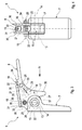
- eine Seitenansicht einer Befestigungsvorrichtung,
- Fig. 4
- eine Frontansicht der Befestigungsvorrichtung entsprechend einer Blickrichtung IV in
Fig. 3 , - Fig. 5a-g
- jeweils eine Seitenansicht der Befestigungsvorrichtung bei unter- schiedlichen Zuständen.
- Fig. 1
- a side view of an attachment, which is attached by means of a holding device to a support member,
- Fig. 2
- a perspective view of the holding device in the assembled state,
- Fig. 2
- a side view of a fastening device,
- Fig. 4
- a front view of the fastening device according to a viewing direction IV in
Fig. 3 . - Fig. 5a-g
- in each case a side view of the fastening device in different states.
Entsprechend
Entsprechend
Entsprechend den
Entsprechend
Entsprechend einer vorteilhaften Weiterbildung kann die jeweilige Drehsicherungseinrichtung 9 außerdem ein Dämpfungselement 12 aufweisen, über das die beiden Platten 4, 5 im montierten Zustand aneinander abgestützt sind. Im Beispiel ist das Dämpfungselement 12 als zylindrische Hülse ausgestaltet und koaxial zum Sicherungsstift 10 angeordnet. Außerdem ist die Stiftaufnahme 11 hier im Inneren des Dämpfungselements 12 angeordnet. Insbesondere kann die Stiftaufnahme 11 in das Dämpfungselement 12 integriert sein. Das Dämpfungselement 12 kann beispielsweise aus einem gummielastischen Kunststoff bestehen.According to an advantageous development, the respective
Entsprechend den
Die Ankerkonsole 8 weist einen Ankerhaken 15 auf, der so ausgestaltet ist, dass er am Ankerbolzen 13 einhakbar ist. Außerdem ist an der Ankerkonsole 8 eine Verriegelungseinrichtung 16 ausgebildet, die zwischen einem z. B. in den
Die Verriegelungseinrichtung 16 umfasst außerdem eine Sicherungseinrichtung 19. Diese ist zwischen einem in den
Die Sicherungseinrichtung 19 umfasst im gezeigten Beispiel ein Sicherungselement 20, das an der Ankerkonsole 8 verstellbar angebracht ist, und zwar derart, dass es zwischen einer in den
Eine in
Bei der hier gezeigten Ausführungsform ist das zuvor genannte Gewinde 21, mit dem die Schraube 20 zusammenwirkt, in einem Gewindekörper 26 ausgebildet. Dieser Gewindekörper 26 ist an die Ankerkonsole 8 angebaut.In the embodiment shown here, the
Der Riegel 17 besitzt an einer dem Ankerbolzen 13 zugewandten Innenseite eine Kreisbogenkontur 27. In der Verriegelungsstellung liegt der Riegel 17 über diese Kreisbogenkontur 27 an einer kreiszylindrischen Außenkontur 28 des Ankerbolzens 13 an. Hierdurch ergibt sich eine vergleichsweise geringe Bauteilbelastung an der Kontaktstelle. Zweckmäßig kann auch der Ankerhaken 15 an einer dem Ankerbolzen 13 zugewandten Innenseite 9 eine Kreisbogenkontur 29 aufweisen, an welcher der Ankerbolzen 13 im eingehakten Zustand anliegt. Auch hier wird eine Reduzierung der Belastung der Kontaktstelle erreicht. Die Kreisbogenkontur 29 des Ankerhakens 15 erstreckt sich dabei um weniger als 180° in der Umfangsrichtung des Ankerbolzens 13. Hierdurch kann der Ankerbolzen 13 einfach in den Ankerhaken 15 eingehakt bzw. daraus ausgehakt werden. Im Unterschied dazu erstreckt sich die Kreisbogenkontur 27 des Riegels 17 z. B. um etwa 90°. Im Verriegelungszustand addieren sich die Kreisbogenkontur 29 des Ankerhakens 15 und die Kreisbogenkontur 27 des Riegels 17, derart, dass der Ankerbolzen 13 im Verriegelungszustand um mehr als 180° umschlungen wird. Im gezeigten Beispiel umschlingen die beiden Kreisbogenkonturen 27 und 29 den Ankerbolzen 13 um etwa 270°. Hierdurch wird ein intensiver Formschluss erreicht, der eine effektive Anbindung der Ankerkonsole 8 am Lagerbock 7 ermöglicht.The
Für eine preiswerte Herstellung kann die Ankerkonsole 8 entsprechend dem hier gezeigten Beispiel zwei voneinander beabstandete Seitenteile 30 und ein Verbindungsteil 31 aufweisen, das die beiden Seitenteile 30 miteinander verbindet. Die beiden Seitenteile 30 sind randseitig so geformt, dass sie jeweils einen Haken 32 aufweisen, wobei die beiden Haken 32 zusammen dann den Ankerhaken 15 bilden. Der Riegel 17 ist zwischen den beiden Seitenteilen 30 angeordnet. Bspw. kann der Riegel 17 mittels einer Schraube 33 und einer Mutter 34 schwenkbar an den Seitenteilen 30 angebracht sein. Auch die Sicherungseinrichtung 19 ist im Beispiel zwischen den beiden Seitenteilen 30 untergebracht. Insbesondere ist der weiter oben genannte Gewindekörper 26 an den Seitenteilen 30 festgelegt. Hierzu können die Seitenteile 30 jeweils eine Öffnung 35 aufweisen, in die ein komplementär geformter Fortsatz des Gewindekörpers 26 formschlüssig eingreift.For an inexpensive production, the
Die Ankerkonsole 8 ist zweckmäßig als Blechformteil konzipiert und kann aus einem einzigen Blechstück durch Umformung hergestellt sein. Auch beim Lagerbock 7 kann es sich um ein Blechformteil handeln. Ebenso kann es sich beim Lagerbock 7 um ein Gussteil handeln. Der Ankerbolzen 13 ist zweckmäßig in den Lagerbock 7 eingesteckt. Dabei kann er mit dem Lagerbock 7 verlötet oder verschweißt sein. Ebenso ist eine Presspassung denkbar. Ferner ist auch eine integrale Ausformung von Lagerbock 7 und Ankerbolzen 13 denkbar.The
Durch die gewählte Formgebung des Ankerbolzens 13, nämlich die zylindrische Außenkontur 28 und die dazu komplementären Innenkonturen 27,29 des Riegels 17 bzw. des Ankerhakens 15, ergibt sich für die Ankerkonsole 8 eine Drehbarkeit um die Längsmittelachse 14 des Ankerbolzens 13, wenn die Ankerkonsole 8 am Lagerbock 7 angeordnet ist. Abhängig von den auftretenden Reibungskräften, kann diese Drehbarkeit auch im Verriegelungszustand und insbesondere auch im Sicherungszustand realisiert werden.Due to the selected shape of the
Bemerkenswert ist ferner, dass im montierten Zustand die Schwenkachse 18 des Riegels 17 oberhalb des Ankerbolzens 13 angeordnet ist und dabei insbesondere vertikal oberhalb der Längsmittelachse 14 des Ankerbolzens 13 verläuft.It is also noteworthy that in the assembled state, the
Im gezeigten Beispiel besitzt der Riegel 17 an einer vom Ankerbolzen 13 abgewandten Außenseite eine ebene Kontaktfläche 36, an welcher sich das Sicherungselement 20, insbesondere über den Abstützkörper 25, abstützt. Diese Abstützung erfolgt im Sicherungszustand senkrecht, d. h., die Verstellrichtung 23 des Sicherungselements 20 steht senkrecht auf der ebenen Außenseite 36 des Riegels 17. Ferner ist der Riegel 17 an seinem von der Schwenkachse 18 entfernten Ende mit einer Rampenkontur 37 ausgestattet, die beim Einhaken des Ankerhakens 15 am Ankerbolzen 13 ein selbsttätiges Aufschwenken des Riegels 17 in eine Entriegelungsstellung ermöglicht. Außerdem ist der Riegel 17 mit einer Anschlagkontur 38 ausgestattet, die bei Erreichen der Verriegelungsstellung an einem entsprechenden Anschlag 39 der Ankerkonsole 8 zur Anlage kommt. Im Beispiel ist der Anschlag 39 durch die dem Riegel 17 zugewandte Innenseite des Verbindungsteils 31 gebildet. Das Zusammenwirken von Anschlagkontur 38 und Anschlag 39 verhindert bei vom Ankerbolzen 13 entferntem Ankerhaken 15 ein über die Verriegelungsstellung hinausgehendes Zuschwenken des Riegels 17, was ein Einhaken des Ankerhakens 15 am Ankerbolzen 13 behindern könnte.In the example shown, the
Das Einhaken der Ankerkonsole 8 am Lagerbock 7 erfolgt entsprechend den
- In den
Fig. 5a bis 5f ist dieSicherungseinrichtung 19 in deren Entsicherungszustand überführt.Das Sicherungselement 20 nimmt seine Entsicherungsstellung ein. In der Folge ist derRiegel 17um seine Schwenkachse 18 frei verschwenkbar.Das Sicherungselement 20 ist dabei aus dem Schwenkweg desRiegels 17 herausbewegt und gibt dadurchden Riegel 17 zum Verschwenken frei. - In
Fig. 5a besteht keine Wechselwirkung zwischen Ankerkonsole 8 undLagerbock 7.Der Riegel 17 nimmt bedingt durch dasZusammenwirken von Anschlagkontur 35 und Anschlag 39 seine Verriegelungsstellung ein. - In
Fig. 5b entsteht durch dieAnnäherung von Ankerkonsole 8 und Lagerbock 7 ein erster Kontakt zwischendem Riegel 17und dem Ankerbolzen 13. Dieser Kontakt findet im Bereich der Rampenkontur 37 desRiegels 17 statt. - Entsprechend
Fig. 5c bewirkt eine weitergehende Annäherung zwischen Ankerhaken 15 und Ankerbolzen 13 durch dasZusammenwirken von Rampenkontur 37 und Ankerbolzen 13 ein Aufschwenken desRiegels 17 in dessen Entriegelungsstellung. - Entsprechend
Fig. 5d und 5e kann derRiegel 17 bei fortschreitender Annäherung zwischen Ankerhaken 15 und Ankerbolzen 13den Ankerbolzen 13 zunehmend umgreifen. - In
Fig. 5f hat der Riegel 17 wieder seine Verriegelungsstellung erreicht, in der erden Ankerbolzen 13 weitgehend umgreift. Gleichzeitigist der Ankerhaken 15 in diesem Zustandvollständig am Ankerbolzen 13 eingehakt. - Anschließend wird nun entsprechend
Fig. 5g die Sicherungseinrichtung in deren Sicherungszustand überführt. Das bedeutet in diesem Fall, dassdas Sicherungselement 20 in seine Sicherungsstellung überführt wird. In diesem Fallist das Sicherungselement 20 in den Schwenkweg desRiegels 17 hineinbewegt. Ferner stützt es sich direkt oder indirektam Riegel 17 ab und verhindert ein Aufschwenken aus der Verriegelungsstellung. Dabei kann entsprechend einemPfeil 40 eine Sicherungskraft in das System eingeleitet werden,um den Riegel 17 gegenden Ankerbolzen 13 und somitden Ankerbolzen 13 inden Ankerhaken 15 vorzuspannen.Die Sicherungskraft 40 kann dabei durch das Zusammenspiel der Anschlagkontur 38mit dem Anschlag 39 begrenzt werden. Ferner kann diese Sicherungskraft 40 auch durch das Anliegen des Schraubenkopfs 22am Gewindekörper 26 begrenzt werden.
- In the
Fig. 5a to 5f thesafety device 19 is transferred to its release state. Thefuse element 20 assumes its release position. As a result, thelatch 17 is freely pivotable about itspivot axis 18. The securingelement 20 is moved out of the pivoting path of thebolt 17 and thereby releases thelatch 17 for pivoting. - In
Fig. 5a there is no interaction betweenanchor bracket 8 andbearing block 7. Thelatch 17 assumes due to the interaction ofstop contour 35 and stop 39 its locking position. - In
Fig. 5b caused by the approach ofanchor bracket 8 andbearing block 7, a first contact between thelatch 17 and theanchor bolt 13. This contact takes place in the region of theramp contour 37 of thebolt 17. - Corresponding
Fig. 5c causes a further approximation between theanchor hook 15 andanchor bolt 13 by the interaction oframp contour 37 andanchor bolt 13 pivoting of thebolt 17 in its unlocked position. - Corresponding
Fig. 5d and 5e can thelatch 17 as the approach betweenanchor hook 15 andanchor bolt 13, theanchor bolt 13 increasingly encompass. - In
Fig. 5f thebolt 17 has again reached its locking position, in which it largely surrounds theanchor bolt 13. At the same time, theanchor hook 15 is fully hooked in this state on theanchor bolt 13. - Subsequently, it will now work accordingly
Fig. 5g transferred the securing device in its security state. That means in this case, that thefuse element 20 is transferred to its securing position. In this case, the securingelement 20 is moved into the pivoting path of thebolt 17. Furthermore, it is supported directly or indirectly on thelatch 17 and prevents pivoting out of the locking position. In this case, according to anarrow 40, a securing force can be introduced into the system to bias thelatch 17 against theanchor bolt 13 and thus theanchor bolt 13 in theanchor hook 15. The securingforce 40 can be limited by the interaction of thestop contour 38 with thestop 39. Furthermore, this securingforce 40 can also be limited by the abutment of thescrew head 22 on the threadedbody 26.
Claims (15)
dadurch gekennzeichnet,
dass die Verriegelungseinrichtung (16) einen Riegel (17) aufweist, der an der Ankerkonsole (8) um eine parallel zum Ankerbolzen (13) verlaufende Schwenkachse (18) zwischen einer Verriegelungsstellung, in welcher der Riegel (17) den Ankerbolzen (13) hintergreift, und einer Entriegelungsstellung verschwenkbar gelagert ist, in welcher der Riegel (17) vom Ankerbolzen (13) freikommt.Fastening device according to claim 1,
characterized,
in that the locking device (16) has a bolt (17) which engages on the anchor bracket (8) about a pivot axis (18) extending parallel to the anchor bolt (13) between a locking position in which the bolt (17) engages behind the anchor bolt (13) , And an unlocking position is pivotally mounted, in which the bolt (17) from the anchor bolt (13) is released.
dadurch gekennzeichnet,
dass die Verriegelungseinrichtung (16) eine Sicherungseinrichtung (19) aufweist, die zwischen einem Sicherungszustand, in dem sie den Riegel (17) in dessen Verriegelungsstellung sichert, und einem Entsicherungszustand verstellbar ist, in dem sie den Riegel (17) freigibt.Fastening device according to claim 2,
characterized,
in that the locking device (16) has a securing device (19) which is disposed between a securing state in which it engages the bolt (17) in its Locking position ensures, and a Entsicherungszustand is adjustable, in which it releases the latch (17).
dadurch gekennzeichnet,
dass die Sicherungseinrichtung (19) ein Sicherungselement (20) aufweist, das an der Ankerkonsole (8) zwischen einer Sicherungsstellung, in der es in einen Schwenkweg des in dessen Verriegelungsstellung überführten Riegels (17) hineinragt und sich direkt oder indirekt am Riegel (17) abstützt, und einer Entsicherungsstellung verstellbar angebracht ist, in der es aus dem Schwenkweg des Riegels (17) heraus bewegt ist.Fastening device according to claim 3,
characterized,
in that the securing device (19) has a securing element (20) which projects on the anchor bracket (8) between a securing position in which it projects into a pivoting path of the bolt (17) transferred into its locking position and directly or indirectly on the bolt (17). supports, and a Entsicherungsstellung is adjustably mounted, in which it is moved out of the pivoting path of the bolt (17) out.
dadurch gekennzeichnet,
dass das Sicherungselement (20) an der Ankerkonsole (8) linear verstellbar angeordnet ist, wobei insbesondere vorgesehen sein kann, dass eine Verstellrichtung (23) des Sicherungselements (20) senkrecht zum Ankerbolzen (13) verläuft und insbesondere im am Ankerhaken (15) eingehängten Zustand senkrecht zu einer Längsmittelachse (14) des Ankerbolzens (13) verläuft.Fastening device according to claim 4,
characterized,
that the securing element (20) on the anchor bracket (8) is arranged linearly adjustable, wherein in particular can be provided that an adjustment (23) of the securing element (20) perpendicular to the anchor bolt (13) and in particular on the anchor hook (15) hinged State perpendicular to a longitudinal central axis (14) of the anchor bolt (13).
dadurch gekennzeichnet,
dass das Sicherungselement (20) einen beweglichen Abstützkörper (25) trägt, über den sich das Sicherungselement (20) in seiner Sicherungsstellung am Riegel (17) abstützt, wobei insbesondere vorgesehen sein kann, dass der Abstützkörper (25) eine Kugelpfannenmutter oder eine Tonnenmutter ist.Fastening device according to claim 4 or 5,
characterized,
in that the securing element (20) carries a movable supporting body (25) via which the securing element (20) is supported in its locking position on the bolt (17), wherein it can be provided in particular that the supporting body (25) is a ball socket nut or a barrel nut ,
dadurch gekennzeichnet,
dass das Sicherungselement als Schraube (20) ausgestaltet ist, die mit einem an der Außenkonsole (8) ausgebildeten Gewinde (21) zusammenwirkt, wobei insbesondere vorgesehen sein kann, dass das Gewinde (21) in einem Gewindekörper (26) ausgebildet ist, der an die Ankerkonsole (8) angebaut ist.Fastening device according to one of claims 4 to 6,
characterized,
in that the securing element is designed as a screw (20) which interacts with a thread (21) formed on the outer console (8), it being possible in particular for the thread (21) to be formed in a threaded body (26) the anchor bracket (8) is attached.
dadurch gekennzeichnet,
dass der Riegel (17) an einer dem Ankerbolzen (13) zugewandten Innenseite eine Kreisbogenkontur (27) aufweist, über die er in seiner Verriegelungsstellung an einer kreiszylindrischen Außenkontur (28) des Ankerbolzens (13) anliegt.Fastening device according to one of claims 2 to 7,
characterized,
that the latch (17) on a side facing the armature bolt (13) inside a circular arc contour (27) over which it abuts in its locking position on a circular-cylindrical outer contour (28) of the anchor bolt (13).
dadurch gekennzeichnet,
dass der Ankerhaken (15) an einer dem Ankerbolzen (13) zugewandten Innenseite eine Kreisbogenkontur (29) aufweist, über die er im eingehakten Zustand an einer kreiszylindrischen Außenkontur (28) des Ankerbolzens (13) anliegt.Fastening device according to one of claims 1 to 8,
characterized,
that the anchor hook (15) on a side facing the armature bolt (13) inside a circular arc contour (29) via which it bears against a circular cylindrical outer contour in the hooked-in state (28) of the anchor bolt (13).
dadurch gekennzeichnet,
characterized,
dadurch gekennzeichnet,
characterized,
dadurch gekennzeichnet,
dass der Riegel (17) zwischen den Seitenteilen (30) angeordnet ist.Fastening device according to claims 2 and 11,
characterized,
in that the latch (17) is arranged between the side parts (30).
dadurch gekennzeichnet,
dass beabstandet zur jeweiligen Befestigungsvorrichtung (6) zumindest eine Drehsicherungseinrichtung (9) vorgesehen ist, die einen an der einen Platte (4) angeordneten Sicherungsstift (10) und eine an der anderen Platte (5) angeordnete Stiftaufnahme (11) aufweist, in die der Sicherungsstift (10) eintaucht.Holding device according to claim 13,
characterized,
in that at least one anti-rotation device (9) is provided at a distance from the respective fastening device (6), which has a locking pin (10) arranged on one plate (4) and a pin receptacle (11) arranged on the other plate (5) into which the Dips in locking pin (10).
dadurch gekennzeichnet,
dass die Drehsicherungseinrichtung (9) ein Dämpfungselement (12) aufweist, über das die Platten (4,5) aneinander abgestützt sind.Holding device according to claim 14,
characterized,
in that the anti-rotation device (9) has a damping element (12) via which the plates (4, 5) are supported on one another.
Applications Claiming Priority (1)
| Application Number | Priority Date | Filing Date | Title |
|---|---|---|---|
| DE200910034722 DE102009034722A1 (en) | 2009-07-24 | 2009-07-24 | Fastening device and holding device |
Publications (2)
| Publication Number | Publication Date |
|---|---|
| EP2284043A1 true EP2284043A1 (en) | 2011-02-16 |
| EP2284043B1 EP2284043B1 (en) | 2012-09-19 |
Family
ID=43066964
Family Applications (1)
| Application Number | Title | Priority Date | Filing Date |
|---|---|---|---|
| EP20100170295 Active EP2284043B1 (en) | 2009-07-24 | 2010-07-21 | Fastening and holding device |
Country Status (3)
| Country | Link |
|---|---|
| US (1) | US8888059B2 (en) |
| EP (1) | EP2284043B1 (en) |
| DE (1) | DE102009034722A1 (en) |
Families Citing this family (12)
| Publication number | Priority date | Publication date | Assignee | Title |
|---|---|---|---|---|
| SE536130C2 (en) * | 2011-10-20 | 2013-05-21 | Scania Cv Ab | Bracket for a vehicle tank |
| US8955288B1 (en) * | 2013-05-06 | 2015-02-17 | Timothy Snyder | Low profile adjustable lift bracket |
| SE537800C2 (en) * | 2014-01-13 | 2015-10-20 | Scania Cv Ab | Suspension device for vehicles |
| US10456208B2 (en) | 2014-03-17 | 2019-10-29 | Intuitive Surgical Operations, Inc. | Surgical cannula mounts and related systems and methods |
| SE540250C2 (en) | 2015-04-29 | 2018-05-15 | Scania Cv Ab | Fastening device, primarily intended for secure installationof components in a vehicle |
| US10081243B2 (en) | 2015-05-03 | 2018-09-25 | Natural Gas Fuel Systems, Inc. | Apparatuses for mounting tanks to vehicles and related methods |
| US9842449B1 (en) * | 2016-11-18 | 2017-12-12 | Motogo, Llc | Secure transport container |
| US10378247B2 (en) * | 2017-03-14 | 2019-08-13 | Harley-Davidson Motor Company Group, LLC | Detachable accessory and latch for same |
| US10981446B2 (en) * | 2017-11-19 | 2021-04-20 | Transfer Flow, Inc. | Adjustable bracket for attaching a tank to the underside of a vehicle or trailer |
| US11861544B2 (en) | 2018-12-21 | 2024-01-02 | Motogo, Llc | System and method for conditional delivery of a transport container |
| IT201900008382A1 (en) * | 2019-06-07 | 2020-12-07 | Givi S P A | SUPPORT AND TILT KIT. |
| US11136085B2 (en) * | 2019-09-12 | 2021-10-05 | Christian K Hampton | Luggage rack wing |
Citations (8)
| Publication number | Priority date | Publication date | Assignee | Title |
|---|---|---|---|---|
| US3784140A (en) * | 1972-09-01 | 1974-01-08 | S Auerbach | Remote fastener for lamps and the like |
| GB2291462A (en) * | 1994-07-12 | 1996-01-24 | Dyfrig Thomas | A coupling with a latchable closing piece |
| DE29922147U1 (en) * | 1999-12-16 | 2000-02-24 | Bertrams Hartwig | Clamp holder |
| US6648286B1 (en) * | 1995-05-30 | 2003-11-18 | Light And Sound Design Ltd. | Lamp-holding hook clamp and connector keyway |
| WO2004113110A1 (en) * | 2003-06-25 | 2004-12-29 | Daimlerchrysler Ag | Device for fixing a container for receiving liquid fuel |
| DE102006044165A1 (en) * | 2006-09-15 | 2008-03-27 | Daimler Ag | Holding device for mounting component part on chassis rail of heavy goods vehicle, has multiple holders at upper and lower area of component part |
| US20080099645A1 (en) * | 2006-11-01 | 2008-05-01 | Joseph Reichley | Golf cart mounted range finder assembly |
| EP2065247A1 (en) * | 2007-11-29 | 2009-06-03 | Alutech Gesellschaft m.b.H. | Vehicle tank and fastening system for same |
Family Cites Families (21)
| Publication number | Priority date | Publication date | Assignee | Title |
|---|---|---|---|---|
| US2381633A (en) * | 1941-10-15 | 1945-08-07 | Young Leonard Weare | Lock and fastening device |
| US4927194A (en) * | 1988-07-14 | 1990-05-22 | Notron Engineering Ag | Interlock latch assembly for releasably securing cowl sections of an outboard motor |
| DE9110272U1 (en) * | 1991-08-20 | 1991-10-17 | Bergmeister, Karl-Heinz, 5653 Leichlingen, De | |
| DE19650402C2 (en) * | 1996-12-05 | 2002-02-07 | Porsche Ag | Convertible top compartment lid for a motor vehicle |
| KR100316952B1 (en) * | 1999-09-13 | 2001-12-22 | 이계안 | Roof ventilators for closed vehicle |
| DE19960022C1 (en) * | 1999-12-13 | 2001-06-07 | Edscha Cabrio Verdecksys Gmbh | Safety system for the release lock at the roof of a convertible automobile has a signal generator which blocks the hand grip movement on an accidental opening action |
| US6443344B1 (en) * | 2000-05-17 | 2002-09-03 | Harley-Davidson Motor Company Group, Inc. | Securing mechanism for detachable motorcycle component |
| DE20019309U1 (en) * | 2000-11-14 | 2001-05-31 | Rewald Containerwechselsysteme | Clamping and locking device for locking hinged hinged doors on container side walls on receptacles |
| US6484914B1 (en) * | 2001-08-17 | 2002-11-26 | Barry A. Willey | Motorcycle accessory mounting system |
| DE10229675B4 (en) * | 2002-06-27 | 2005-06-09 | Bos Gmbh & Co. Kg | Locking device for a motor vehicle |
| US6767047B2 (en) * | 2002-08-15 | 2004-07-27 | Asc Incorporated | Convertible roof latch |
| US7021696B2 (en) * | 2002-11-14 | 2006-04-04 | Asc Incorporated | Convertible top latch |
| US7150382B2 (en) * | 2003-12-09 | 2006-12-19 | Zickefoose Mark S | Attachment to motorcycle to safely transport musical instruments |
| JP3578172B1 (en) * | 2003-12-19 | 2004-10-20 | 松下電器産業株式会社 | Vacuum insulation, refrigerators and refrigerators |
| DE102004040157B3 (en) * | 2004-08-19 | 2006-07-13 | Huf Hülsbeck & Fürst Gmbh & Co. Kg | Lock for doors or flaps on vehicles |
| US7090280B2 (en) * | 2004-10-22 | 2006-08-15 | Willey Barry A | Mounting system for accessories |
| US7454933B1 (en) * | 2005-03-14 | 2008-11-25 | The Eastern Company | Handle and housing assembly |
| DE202005018342U1 (en) * | 2005-11-22 | 2006-12-28 | Edscha Lkw-Schiebeverdecke Gmbh | Stanchion holding tarpaulin bow frame, comprising toothed quick lifting and lowering mechanism |
| US7654496B2 (en) * | 2006-02-09 | 2010-02-02 | Summit Industries, Inc. | Quick release bracket |
| US7946632B1 (en) * | 2007-02-20 | 2011-05-24 | Mueller Allen B | Apparatus for attaching accessories to a motorcycle |
| JP5177536B2 (en) * | 2008-09-25 | 2013-04-03 | アイシン精機株式会社 | Open roof opening and closing device |
-
2009
- 2009-07-24 DE DE200910034722 patent/DE102009034722A1/en not_active Withdrawn
-
2010
- 2010-06-28 US US12/824,537 patent/US8888059B2/en active Active
- 2010-07-21 EP EP20100170295 patent/EP2284043B1/en active Active
Patent Citations (8)
| Publication number | Priority date | Publication date | Assignee | Title |
|---|---|---|---|---|
| US3784140A (en) * | 1972-09-01 | 1974-01-08 | S Auerbach | Remote fastener for lamps and the like |
| GB2291462A (en) * | 1994-07-12 | 1996-01-24 | Dyfrig Thomas | A coupling with a latchable closing piece |
| US6648286B1 (en) * | 1995-05-30 | 2003-11-18 | Light And Sound Design Ltd. | Lamp-holding hook clamp and connector keyway |
| DE29922147U1 (en) * | 1999-12-16 | 2000-02-24 | Bertrams Hartwig | Clamp holder |
| WO2004113110A1 (en) * | 2003-06-25 | 2004-12-29 | Daimlerchrysler Ag | Device for fixing a container for receiving liquid fuel |
| DE102006044165A1 (en) * | 2006-09-15 | 2008-03-27 | Daimler Ag | Holding device for mounting component part on chassis rail of heavy goods vehicle, has multiple holders at upper and lower area of component part |
| US20080099645A1 (en) * | 2006-11-01 | 2008-05-01 | Joseph Reichley | Golf cart mounted range finder assembly |
| EP2065247A1 (en) * | 2007-11-29 | 2009-06-03 | Alutech Gesellschaft m.b.H. | Vehicle tank and fastening system for same |
Also Published As
| Publication number | Publication date |
|---|---|
| US20110017885A1 (en) | 2011-01-27 |
| EP2284043B1 (en) | 2012-09-19 |
| DE102009034722A1 (en) | 2011-01-27 |
| US8888059B2 (en) | 2014-11-18 |
Similar Documents
| Publication | Publication Date | Title |
|---|---|---|
| EP2284043B1 (en) | Fastening and holding device | |
| WO1997010111A1 (en) | Motor vehicle trailer coupling | |
| EP0380974A2 (en) | Adaptator for the clamping of a supplementary tool | |
| WO2009132755A1 (en) | Method and fastening device for fastening a vehicle part to a vehicle | |
| DE2914844C2 (en) | Quick clamping device, in particular for balancing machines for balancing vehicle wheels | |
| DE102017209308A1 (en) | Additional wheel weight for a commercial vehicle | |
| DE102017009176B4 (en) | Coupling device | |
| DE102013107730A1 (en) | Special motor vehicle with locking unit for box body | |
| DE3630804C2 (en) | ||
| EP3386678A1 (en) | Device for the automated coupling and decoupling of a tool attachment, as well as method for the automated connection of at least two workpieces | |
| DE102013108807A1 (en) | Fastening device for vehicle equipment | |
| DE10023641A1 (en) | Trailer coupling for private motor vehicles has motor spindle drive unit with casing containing electric drive motor, and rotating threaded spindle protruding from casing and engaging with pivot-mounted stationary spindle nut | |
| EP2145805B1 (en) | Windscreen wiper assembly with fixing component and fixing component | |
| DE202018101859U1 (en) | Device for fixing a battery trough of a truck | |
| EP1203836B1 (en) | Opening rollers for open-end spinning machines | |
| DE2416645A1 (en) | RESERVE OR EMERGENCY BIKE FOR MOTOR VEHICLES | |
| AT504478B1 (en) | Hold-down device for coupling of drawing vehicle, has fastening bolt arranged for fixation into aperture at coupling position and formed opposite to aperture, which is designed in bent-form | |
| EP2918758B1 (en) | Locking device | |
| EP3290308B1 (en) | Fastening and supporting device and trailer | |
| DE102020203467A1 (en) | Filter device | |
| EP0416448A1 (en) | Lock, specially for outside swing doors of buses | |
| DE19922752A1 (en) | Load bearing system for mounting on ball of ball joint for suspension coupling of vehicle has component with unit that secures rotation, which is fitted onto ball and hinged load support to fix unit | |
| EP3524565A1 (en) | Battery lock | |
| AT525378B1 (en) | dome triangle | |
| AT412860B (en) | Support structure for hitch ball of coupling mechanism, has support unit with fastening mechanism for securement of support unit to carrier through quick-action coupling |
Legal Events
| Date | Code | Title | Description |
|---|---|---|---|
| PUAI | Public reference made under article 153(3) epc to a published international application that has entered the european phase |
Free format text: ORIGINAL CODE: 0009012 |
|
| AK | Designated contracting states |
Kind code of ref document: A1 Designated state(s): AL AT BE BG CH CY CZ DE DK EE ES FI FR GB GR HR HU IE IS IT LI LT LU LV MC MK MT NL NO PL PT RO SE SI SK SM TR |
|
| AX | Request for extension of the european patent |
Extension state: BA ME RS |
|
| 17P | Request for examination filed |
Effective date: 20110816 |
|
| 17Q | First examination report despatched |
Effective date: 20110912 |
|
| REG | Reference to a national code |
Ref country code: DE Ref legal event code: R079 Ref document number: 502010001293 Country of ref document: DE Free format text: PREVIOUS MAIN CLASS: B60R0011000000 Ipc: B60K0015067000 |
|
| GRAP | Despatch of communication of intention to grant a patent |
Free format text: ORIGINAL CODE: EPIDOSNIGR1 |
|
| RIC1 | Information provided on ipc code assigned before grant |
Ipc: B60R 11/00 20060101ALI20120514BHEP Ipc: B60K 15/067 20060101AFI20120514BHEP |
|
| GRAS | Grant fee paid |
Free format text: ORIGINAL CODE: EPIDOSNIGR3 |
|
| GRAA | (expected) grant |
Free format text: ORIGINAL CODE: 0009210 |
|
| AK | Designated contracting states |
Kind code of ref document: B1 Designated state(s): AL AT BE BG CH CY CZ DE DK EE ES FI FR GB GR HR HU IE IS IT LI LT LU LV MC MK MT NL NO PL PT RO SE SI SK SM TR |
|
| REG | Reference to a national code |
Ref country code: GB Ref legal event code: FG4D Free format text: NOT ENGLISH |
|
| REG | Reference to a national code |
Ref country code: CH Ref legal event code: EP |
|
| REG | Reference to a national code |
Ref country code: IE Ref legal event code: FG4D Free format text: LANGUAGE OF EP DOCUMENT: GERMAN |
|
| REG | Reference to a national code |
Ref country code: AT Ref legal event code: REF Ref document number: 575814 Country of ref document: AT Kind code of ref document: T Effective date: 20121015 |
|
| REG | Reference to a national code |
Ref country code: DE Ref legal event code: R096 Ref document number: 502010001293 Country of ref document: DE Effective date: 20121108 |
|
| REG | Reference to a national code |
Ref country code: SE Ref legal event code: TRGR |
|
| PG25 | Lapsed in a contracting state [announced via postgrant information from national office to epo] |
Ref country code: LT Free format text: LAPSE BECAUSE OF FAILURE TO SUBMIT A TRANSLATION OF THE DESCRIPTION OR TO PAY THE FEE WITHIN THE PRESCRIBED TIME-LIMIT Effective date: 20120919 Ref country code: FI Free format text: LAPSE BECAUSE OF FAILURE TO SUBMIT A TRANSLATION OF THE DESCRIPTION OR TO PAY THE FEE WITHIN THE PRESCRIBED TIME-LIMIT Effective date: 20120919 Ref country code: NO Free format text: LAPSE BECAUSE OF FAILURE TO SUBMIT A TRANSLATION OF THE DESCRIPTION OR TO PAY THE FEE WITHIN THE PRESCRIBED TIME-LIMIT Effective date: 20121219 Ref country code: HR Free format text: LAPSE BECAUSE OF FAILURE TO SUBMIT A TRANSLATION OF THE DESCRIPTION OR TO PAY THE FEE WITHIN THE PRESCRIBED TIME-LIMIT Effective date: 20120919 |
|
| REG | Reference to a national code |
Ref country code: NL Ref legal event code: VDEP Effective date: 20120919 |
|
| REG | Reference to a national code |
Ref country code: LT Ref legal event code: MG4D Effective date: 20120919 |
|
| PG25 | Lapsed in a contracting state [announced via postgrant information from national office to epo] |
Ref country code: GR Free format text: LAPSE BECAUSE OF FAILURE TO SUBMIT A TRANSLATION OF THE DESCRIPTION OR TO PAY THE FEE WITHIN THE PRESCRIBED TIME-LIMIT Effective date: 20121220 Ref country code: LV Free format text: LAPSE BECAUSE OF FAILURE TO SUBMIT A TRANSLATION OF THE DESCRIPTION OR TO PAY THE FEE WITHIN THE PRESCRIBED TIME-LIMIT Effective date: 20120919 Ref country code: SI Free format text: LAPSE BECAUSE OF FAILURE TO SUBMIT A TRANSLATION OF THE DESCRIPTION OR TO PAY THE FEE WITHIN THE PRESCRIBED TIME-LIMIT Effective date: 20120919 |
|
| PG25 | Lapsed in a contracting state [announced via postgrant information from national office to epo] |
Ref country code: RO Free format text: LAPSE BECAUSE OF FAILURE TO SUBMIT A TRANSLATION OF THE DESCRIPTION OR TO PAY THE FEE WITHIN THE PRESCRIBED TIME-LIMIT Effective date: 20120919 Ref country code: IS Free format text: LAPSE BECAUSE OF FAILURE TO SUBMIT A TRANSLATION OF THE DESCRIPTION OR TO PAY THE FEE WITHIN THE PRESCRIBED TIME-LIMIT Effective date: 20130119 Ref country code: EE Free format text: LAPSE BECAUSE OF FAILURE TO SUBMIT A TRANSLATION OF THE DESCRIPTION OR TO PAY THE FEE WITHIN THE PRESCRIBED TIME-LIMIT Effective date: 20120919 Ref country code: ES Free format text: LAPSE BECAUSE OF FAILURE TO SUBMIT A TRANSLATION OF THE DESCRIPTION OR TO PAY THE FEE WITHIN THE PRESCRIBED TIME-LIMIT Effective date: 20121230 Ref country code: CZ Free format text: LAPSE BECAUSE OF FAILURE TO SUBMIT A TRANSLATION OF THE DESCRIPTION OR TO PAY THE FEE WITHIN THE PRESCRIBED TIME-LIMIT Effective date: 20120919 Ref country code: NL Free format text: LAPSE BECAUSE OF FAILURE TO SUBMIT A TRANSLATION OF THE DESCRIPTION OR TO PAY THE FEE WITHIN THE PRESCRIBED TIME-LIMIT Effective date: 20120919 |
|
| PG25 | Lapsed in a contracting state [announced via postgrant information from national office to epo] |
Ref country code: PL Free format text: LAPSE BECAUSE OF FAILURE TO SUBMIT A TRANSLATION OF THE DESCRIPTION OR TO PAY THE FEE WITHIN THE PRESCRIBED TIME-LIMIT Effective date: 20120919 Ref country code: PT Free format text: LAPSE BECAUSE OF FAILURE TO SUBMIT A TRANSLATION OF THE DESCRIPTION OR TO PAY THE FEE WITHIN THE PRESCRIBED TIME-LIMIT Effective date: 20130121 Ref country code: SK Free format text: LAPSE BECAUSE OF FAILURE TO SUBMIT A TRANSLATION OF THE DESCRIPTION OR TO PAY THE FEE WITHIN THE PRESCRIBED TIME-LIMIT Effective date: 20120919 |
|
| RAP2 | Party data changed (patent owner data changed or rights of a patent transferred) |
Owner name: EBERSPAECHER EXHAUST TECHNOLOGY GMBH & CO. KG |
|
| PLBE | No opposition filed within time limit |
Free format text: ORIGINAL CODE: 0009261 |
|
| STAA | Information on the status of an ep patent application or granted ep patent |
Free format text: STATUS: NO OPPOSITION FILED WITHIN TIME LIMIT |
|
| PG25 | Lapsed in a contracting state [announced via postgrant information from national office to epo] |
Ref country code: BG Free format text: LAPSE BECAUSE OF FAILURE TO SUBMIT A TRANSLATION OF THE DESCRIPTION OR TO PAY THE FEE WITHIN THE PRESCRIBED TIME-LIMIT Effective date: 20121219 Ref country code: DK Free format text: LAPSE BECAUSE OF FAILURE TO SUBMIT A TRANSLATION OF THE DESCRIPTION OR TO PAY THE FEE WITHIN THE PRESCRIBED TIME-LIMIT Effective date: 20120919 |
|
| 26N | No opposition filed |
Effective date: 20130620 |
|
| REG | Reference to a national code |
Ref country code: GB Ref legal event code: 732E Free format text: REGISTERED BETWEEN 20130905 AND 20130911 |
|
| REG | Reference to a national code |
Ref country code: DE Ref legal event code: R097 Ref document number: 502010001293 Country of ref document: DE Effective date: 20130620 |
|
| REG | Reference to a national code |
Ref country code: DE Ref legal event code: R082 Ref document number: 502010001293 Country of ref document: DE Representative=s name: BRP RENAUD & PARTNER, DE |
|
| PG25 | Lapsed in a contracting state [announced via postgrant information from national office to epo] |
Ref country code: CY Free format text: LAPSE BECAUSE OF FAILURE TO SUBMIT A TRANSLATION OF THE DESCRIPTION OR TO PAY THE FEE WITHIN THE PRESCRIBED TIME-LIMIT Effective date: 20120919 |
|
| REG | Reference to a national code |
Ref country code: DE Ref legal event code: R082 Ref document number: 502010001293 Country of ref document: DE Representative=s name: BRP RENAUD UND PARTNER MBB, DE Effective date: 20131022 Ref country code: DE Ref legal event code: R082 Ref document number: 502010001293 Country of ref document: DE Representative=s name: BRP RENAUD UND PARTNER MBB RECHTSANWAELTE PATE, DE Effective date: 20131022 Ref country code: DE Ref legal event code: R081 Ref document number: 502010001293 Country of ref document: DE Owner name: EBERSPAECHER EXHAUST TECHNOLOGY GMBH & CO. KG, DE Free format text: FORMER OWNER: J. EBERSPAECHER GMBH & CO. KG, 73730 ESSLINGEN, DE Effective date: 20131022 Ref country code: DE Ref legal event code: R082 Ref document number: 502010001293 Country of ref document: DE Representative=s name: BRP RENAUD & PARTNER, DE Effective date: 20131022 |
|
| BERE | Be: lapsed |
Owner name: J. EBERSPACHER G.M.B.H. & CO. KG Effective date: 20130731 |
|
| PG25 | Lapsed in a contracting state [announced via postgrant information from national office to epo] |
Ref country code: MC Free format text: LAPSE BECAUSE OF FAILURE TO SUBMIT A TRANSLATION OF THE DESCRIPTION OR TO PAY THE FEE WITHIN THE PRESCRIBED TIME-LIMIT Effective date: 20120919 |
|
| REG | Reference to a national code |
Ref country code: IE Ref legal event code: MM4A |
|
| PG25 | Lapsed in a contracting state [announced via postgrant information from national office to epo] |
Ref country code: BE Free format text: LAPSE BECAUSE OF NON-PAYMENT OF DUE FEES Effective date: 20130731 |
|
| PG25 | Lapsed in a contracting state [announced via postgrant information from national office to epo] |
Ref country code: IE Free format text: LAPSE BECAUSE OF NON-PAYMENT OF DUE FEES Effective date: 20130721 |
|
| REG | Reference to a national code |
Ref country code: CH Ref legal event code: PL |
|
| PG25 | Lapsed in a contracting state [announced via postgrant information from national office to epo] |
Ref country code: CH Free format text: LAPSE BECAUSE OF NON-PAYMENT OF DUE FEES Effective date: 20140731 Ref country code: LI Free format text: LAPSE BECAUSE OF NON-PAYMENT OF DUE FEES Effective date: 20140731 |
|
| PG25 | Lapsed in a contracting state [announced via postgrant information from national office to epo] |
Ref country code: SM Free format text: LAPSE BECAUSE OF FAILURE TO SUBMIT A TRANSLATION OF THE DESCRIPTION OR TO PAY THE FEE WITHIN THE PRESCRIBED TIME-LIMIT Effective date: 20120919 |
|
| PG25 | Lapsed in a contracting state [announced via postgrant information from national office to epo] |
Ref country code: MT Free format text: LAPSE BECAUSE OF FAILURE TO SUBMIT A TRANSLATION OF THE DESCRIPTION OR TO PAY THE FEE WITHIN THE PRESCRIBED TIME-LIMIT Effective date: 20120919 Ref country code: TR Free format text: LAPSE BECAUSE OF FAILURE TO SUBMIT A TRANSLATION OF THE DESCRIPTION OR TO PAY THE FEE WITHIN THE PRESCRIBED TIME-LIMIT Effective date: 20120919 |
|
| PG25 | Lapsed in a contracting state [announced via postgrant information from national office to epo] |
Ref country code: MK Free format text: LAPSE BECAUSE OF FAILURE TO SUBMIT A TRANSLATION OF THE DESCRIPTION OR TO PAY THE FEE WITHIN THE PRESCRIBED TIME-LIMIT Effective date: 20120919 Ref country code: HU Free format text: LAPSE BECAUSE OF FAILURE TO SUBMIT A TRANSLATION OF THE DESCRIPTION OR TO PAY THE FEE WITHIN THE PRESCRIBED TIME-LIMIT; INVALID AB INITIO Effective date: 20100721 Ref country code: LU Free format text: LAPSE BECAUSE OF NON-PAYMENT OF DUE FEES Effective date: 20130721 |
|
| REG | Reference to a national code |
Ref country code: FR Ref legal event code: PLFP Year of fee payment: 7 |
|
| REG | Reference to a national code |
Ref country code: AT Ref legal event code: MM01 Ref document number: 575814 Country of ref document: AT Kind code of ref document: T Effective date: 20150721 |
|
| PG25 | Lapsed in a contracting state [announced via postgrant information from national office to epo] |
Ref country code: AT Free format text: LAPSE BECAUSE OF NON-PAYMENT OF DUE FEES Effective date: 20150721 |
|
| REG | Reference to a national code |
Ref country code: FR Ref legal event code: PLFP Year of fee payment: 8 |
|
| PGFP | Annual fee paid to national office [announced via postgrant information from national office to epo] |
Ref country code: IT Payment date: 20170721 Year of fee payment: 8 |
|
| REG | Reference to a national code |
Ref country code: FR Ref legal event code: PLFP Year of fee payment: 9 |
|
| PG25 | Lapsed in a contracting state [announced via postgrant information from national office to epo] |
Ref country code: AL Free format text: LAPSE BECAUSE OF FAILURE TO SUBMIT A TRANSLATION OF THE DESCRIPTION OR TO PAY THE FEE WITHIN THE PRESCRIBED TIME-LIMIT Effective date: 20120919 |
|
| PG25 | Lapsed in a contracting state [announced via postgrant information from national office to epo] |
Ref country code: IT Free format text: LAPSE BECAUSE OF NON-PAYMENT OF DUE FEES Effective date: 20180721 |
|
| REG | Reference to a national code |
Ref country code: DE Ref legal event code: R081 Ref document number: 502010001293 Country of ref document: DE Owner name: PUREM GMBH, DE Free format text: FORMER OWNER: EBERSPAECHER EXHAUST TECHNOLOGY GMBH & CO. KG, 66539 NEUNKIRCHEN, DE |
|
| PGFP | Annual fee paid to national office [announced via postgrant information from national office to epo] |
Ref country code: GB Payment date: 20230724 Year of fee payment: 14 |
|
| PGFP | Annual fee paid to national office [announced via postgrant information from national office to epo] |
Ref country code: SE Payment date: 20230724 Year of fee payment: 14 Ref country code: FR Payment date: 20230724 Year of fee payment: 14 Ref country code: DE Payment date: 20230720 Year of fee payment: 14 |