EP2283719A2 - Anordnung zur seitlichen verstellbaren Anbringung eines landwirtschaftlichen Arbeitsgeräts an einem Fahrzeug - Google Patents
Anordnung zur seitlichen verstellbaren Anbringung eines landwirtschaftlichen Arbeitsgeräts an einem Fahrzeug Download PDFInfo
- Publication number
- EP2283719A2 EP2283719A2 EP10170067A EP10170067A EP2283719A2 EP 2283719 A2 EP2283719 A2 EP 2283719A2 EP 10170067 A EP10170067 A EP 10170067A EP 10170067 A EP10170067 A EP 10170067A EP 2283719 A2 EP2283719 A2 EP 2283719A2
- Authority
- EP
- European Patent Office
- Prior art keywords
- arrangement
- vehicle
- implement
- attachable
- coupling
- Prior art date
- Legal status (The legal status is an assumption and is not a legal conclusion. Google has not performed a legal analysis and makes no representation as to the accuracy of the status listed.)
- Granted
Links
- 230000008878 coupling Effects 0.000 claims description 23
- 238000010168 coupling process Methods 0.000 claims description 23
- 238000005859 coupling reaction Methods 0.000 claims description 23
- 238000003971 tillage Methods 0.000 description 3
Images


Classifications
-
- A—HUMAN NECESSITIES
- A01—AGRICULTURE; FORESTRY; ANIMAL HUSBANDRY; HUNTING; TRAPPING; FISHING
- A01B—SOIL WORKING IN AGRICULTURE OR FORESTRY; PARTS, DETAILS, OR ACCESSORIES OF AGRICULTURAL MACHINES OR IMPLEMENTS, IN GENERAL
- A01B59/00—Devices specially adapted for connection between animals or tractors and agricultural machines or implements
- A01B59/06—Devices specially adapted for connection between animals or tractors and agricultural machines or implements for machines mounted on tractors
- A01B59/066—Devices specially adapted for connection between animals or tractors and agricultural machines or implements for machines mounted on tractors of the type comprising at least two lower arms and one upper arm generally arranged in a triangle (e.g. three-point hitches)
-
- A—HUMAN NECESSITIES
- A01—AGRICULTURE; FORESTRY; ANIMAL HUSBANDRY; HUNTING; TRAPPING; FISHING
- A01B—SOIL WORKING IN AGRICULTURE OR FORESTRY; PARTS, DETAILS, OR ACCESSORIES OF AGRICULTURAL MACHINES OR IMPLEMENTS, IN GENERAL
- A01B59/00—Devices specially adapted for connection between animals or tractors and agricultural machines or implements
- A01B59/06—Devices specially adapted for connection between animals or tractors and agricultural machines or implements for machines mounted on tractors
- A01B59/061—Devices specially adapted for connection between animals or tractors and agricultural machines or implements for machines mounted on tractors specially adapted for enabling connection or disconnection controlled from the driver's seat
- A01B59/062—Devices specially adapted for connection between animals or tractors and agricultural machines or implements for machines mounted on tractors specially adapted for enabling connection or disconnection controlled from the driver's seat the connection comprising a rigid interface frame on the tractor
-
- A—HUMAN NECESSITIES
- A01—AGRICULTURE; FORESTRY; ANIMAL HUSBANDRY; HUNTING; TRAPPING; FISHING
- A01B—SOIL WORKING IN AGRICULTURE OR FORESTRY; PARTS, DETAILS, OR ACCESSORIES OF AGRICULTURAL MACHINES OR IMPLEMENTS, IN GENERAL
- A01B63/00—Lifting or adjusting devices or arrangements for agricultural machines or implements
- A01B63/02—Lifting or adjusting devices or arrangements for agricultural machines or implements for implements mounted on tractors
- A01B63/023—Lateral adjustment of their tools
Definitions
- a lateral adjustment of the implement relative to the tractor makes sense to achieve that the implement on a desired path is performed while the tractor for different possible reasons may deviate from the desired path, for example due to unfavorable ground properties or on a side slope or by inattention of the operator directing him.
- This lateral adjustment takes place in the prior art, for example according to the US 7 162 348 B2 by a tractor-side drawbar, which is articulated at its front end about the vertical axis pivotally and is moved by arranged on its two sides hydraulic cylinder in the lateral direction.
- a drawbar of the implement is attached at the rear end of the drawbar.
- the current position of the tractor is detected by means of a DGPS antenna attached to its roof and the hydraulic cylinders are controlled so that the implement is guided on the intended target path, including feedback signals from a potentiometer to detect the position of one of the hydraulic cylinders be used.
- This arrangement in which the drawbar of the implement is pivotally mounted about the vertical axis on the drawbar, is only suitable for tools that support themselves on the ground, be it by wheels or their tillage tools.
- the implement includes a first element that is mounted to the tractor's three-point hitch.
- a second element of the implement carries the tillage tools and is connected by parallelogram link with the first element.
- An arranged between the first and the second element hydraulic cylinder is used for lateral adjustment of the second element. It is driven based on signals from two GPS antennas, one attached to the tractor or to the first element and the other attached to the second element.
- the hydraulic cylinder and at least the attached to the second element GPS antenna can be used only for a single implement.
- the problem underlying the invention is seen to provide an arrangement for laterally adjustable attachment of an agricultural implement to a carrier vehicle, which can be used universally for different types of implements.
- An arrangement for the laterally adjustable attachment of an agricultural implement to a vehicle is composed of a first element, which is attachable to a three-point coupling of the vehicle and a second element, to which the implement is detachably attachable.
- the second element is displaceable by means of a power-operated actuator relative to the first element in the horizontal and transversely to the forward direction.
- the actuator can be controlled based on position signals and a desired path information such that the second element is guided with the implement along a desired path.
- the three-point hitch can be located at the front or rear of the vehicle.
- the vehicle may be self-propelled, in particular a tractor, or it may be moved across another field by another vehicle.
- the arrangement according to the invention can be used for attachment of any equipment.
- the slidable attachment of the second element relative to the first element has the advantage over the vertical axis of the prior art that there is no longer any movement of the working device in the forward direction, which in many cases is considered disadvantageous.
- the second element is preferably designed for attachment of different coupling devices of implements, to which a lower, horizontally and transversely extending to the forward direction rail may be provided at the one or more lower link crosspoints and / or a Switzerlandmaul and / or a ball coupling and / or or a drawbar and / or a field rail in the lateral direction is adjustable attachable or are.
- the mentioned coupling devices expediently comprise a section which surrounds or at least engages behind the rail.
- the second element also preferably has an upper coupling point to which a top link with fixed or (manually or hydraulically) adjustable length can be attached in order to adjust the position of the implement can.
- the first element and the second element each comprise a frame whose shape is preferably at least approximately rectangular and whose corners may be rectangular or rounded.
- the first element is wider than the second element, which is laterally displaced by the actuator along the first element.
- the frames are preferably sufficient space for the passage of a PTO free.
- a vehicle 10 is shown in the form of an agricultural tractor, which builds on a frame 12 and supported by front, steerable wheels 14 and drivable, rear wheels 16 on the ground.
- the operator work station is located in a cabin 18.
- a three-point coupling 20 is arranged, which is composed of two juxtaposed lower links 22 and a top link 28.
- the lower links 22 are height adjustable by hydraulic cylinders 26.
- the upper link 28 is variable in length by a hydraulic cylinder 24. By adjusting the hydraulic cylinder 26, the working height of a working device 36 can be changed.
- the inclination angle of the implement 36 is adjustable.
- lower link coupling points 30 in the form of catch hooks extending upward (or any other coupling points, eg coupling eyes, as described in DIN ISO 730-1 Agricultural Machinery and Tractors - Heck- Three-point hitching - Part 1: Categories 1, 2, 3 and 4 are described), while at the rear end of the upper link 28, a likewise conventional top link coupling point 32 is provided.
- an assembly 34 for laterally adjustable attachment of an agricultural implement 36 is removably attached.
- the assembly 34 includes a frame-shaped first member 38 secured by lower flaps 40 and bolts 42 to the lower link coupling points 30 of the lower links 22 and by an upper support member 44 and a bolt 44 at the upper link coupling point 32.
- the arrangement 34 comprises a frame-shaped second element 48 whose width measured transversely to the forward direction of the vehicle is smaller than that of the first element 38.
- the second element 48 is supported by a lower support 50 which engages around a rod-shaped support 52 connected to the first element 38, from below and from the front, and an upper support 54 which is connected to the first element 38, attached to the top, rod-shaped support 56 engages from above and front, on the first element 38 from.
- a lower support 50 which engages around a rod-shaped support 52 connected to the first element 38, from below and from the front
- an upper support 54 which is connected to the first element 38, attached to the top
- rod-shaped support 56 engages from above and front, on the first element 38 from.
- Between the brackets 52 and 56 on the one hand and the brackets 50 and 54 on the other hand could also bearings or other friction-reducing elements, such as plastic layers, are installed to reduce the friction.
- the second element 48 is opposite the first element 38 by means of a in the upper region of the assembly 34 between the elements 38, 48 extending actuator 58 in the form of a hydraulic cylinder (see. Figures 2 and 3 ) in the lateral direction (ie horizontally and transversely to the forward direction of the vehicle 10) displaceable.
- the actuator 58 is connected to a controller 60 which sends it based on a target path map stored in a memory of the controller 60, position information from an antenna 62 mounted on the roof of the car 18 for receiving signals from satellites of a global positioning system (e.g.
- GPS Globalstar Satellite System
- a sensor preferably installed in the housing of the actuator 58 Detecting the position of the actuator 58 and / or an attached to the implement 36 antenna 62 for receiving signals from satellites of a global positioning system such that the working device 36 is moved along the desired path.
- the steering of the vehicle 10 can also be accomplished automatically by the controller 60 or by its driver. Details of the control of the actuator 58, the writings US 7 162 348 B2 and US Pat. No. 7,460,942 B2 the disclosure of which is incorporated by reference into the present documentation.
- the information about the current position of the vehicle 10 and / or the implement 36 could also be provided by a camera or a laser scanner scanning the field ahead of the vehicle.
- the Sollweginformation is defined by steering signals of the vehicle and the position signals are generated from the aforementioned, the position of the second element relative to the first element detecting sensor (not shown) to achieve that as little overlap and uncut material as possible is achieved at the front and rear of the vehicle mounted mowers.
- the controller 60 by means of the hydraulic cylinders 26 and 24 and the working height of the working device 36 control, be it site-specific based on the Sollweg badge or only in the headland.
- the second element 48 comprises at its lower end a rail 66 to which the lower link coupling points 68 are detachably and mounted in a laterally displaceable manner, which by the rail 66 completely or partially enclosing fasteners 84 (see. FIG. 2 ), since the rail 66 is spaced from the second member 48.
- the second element 48 comprises at its upper end an upper coupling point 70.
- the working device 36 comprises a frame 72 with a vertically extending support frame 74 mounted on its front portion.
- the support frame 74 is connected at its lower end to struts 76 which again by bolts 78 in the lower link coupling points 68 engage and support it.
- the support frame 74 is connected at its upper end with a top link 80, which in turn is fixed by a bolt 82 at the upper coupling point 70.
- a top link 80 fixed length could also be a manual or hydraulic length-adjustable upper link can be used.
- the inventive arrangement 34 for laterally adjustable attachment of the implement 36 between the three-point interfaces of the vehicle 10 and the implement 36 is inserted and allows automatic lateral adjustment of the implement 36 relative to the vehicle 10 to the implement 36 on to lead a desired path.
- the track 66 also allows any other attachment means for attachments, such as a towing jaw, ball-and-socket coupling, drawbar, or field rail (not shown), to be used in place of the lower link coupling points 68.
- the frame shape of the elements 38, 48 has the advantage that, if necessary, a power take-off shaft (not shown) can be passed therethrough in order to drive a drivable working device with it.
Landscapes
- Life Sciences & Earth Sciences (AREA)
- Engineering & Computer Science (AREA)
- Mechanical Engineering (AREA)
- Soil Sciences (AREA)
- Environmental Sciences (AREA)
- Zoology (AREA)
- Agricultural Machines (AREA)
- Guiding Agricultural Machines (AREA)
Abstract
Description
- Die Erfindung betrifft eine Anordnung zur seitlich verstellbaren Anbringung eines landwirtschaftlichen Arbeitsgeräts an einem Fahrzeug, umfassend:
- ein erstes Element, das an einer Dreipunktkupplung des Fahrzeugs anbringbar ist,
- ein zweites Element, das mittels eines fremdkraftbetätigten Aktors gegenüber dem ersten Element in einer horizontalen und quer zur Vorwärtsrichtung verlaufenden Richtung bewegbar und an dem das Arbeitsgerät anbringbar ist, wobei der Aktor im Betrieb basierend auf Positionssignalen und einer Sollweginformation derart ansteuerbar ist, dass das zweite Element mit dem Arbeitsgerät entlang eines Sollwegs geführt wird.
- Bei landwirtschaftlichen Arbeitsgeräten, die beispielsweise zur Bodenbearbeitung, zum Düngen, Mähen oder ähnlichen landwirtschaftlichen Arbeitsvorgängen dienen und mittels eines Traktors über ein Feld bewegt werden, ist in vielen Fällen eine seitliche Verstellung des Arbeitsgeräts gegenüber dem Traktor sinnvoll, um zu erreichen, dass das Arbeitsgerät auf einem Sollweg geführt wird, während der Traktor aus unterschiedlichen denkbaren Gründen von dem Sollweg abweichen kann, beispielsweise aufgrund ungünstiger Bodeneigenschaften oder an einem Seitenhang oder durch Unaufmerksamkeit des ihn lenkenden Bedieners.
- Diese seitliche Verstellung erfolgt im Stand der Technik beispielsweise gemäß der
US 7 162 348 B2 durch einen traktorseitigen Zugbalken, der an seinem vorderen Ende um die Hochachse schwenkbar angelenkt ist und durch an seinen beiden Seiten angeordnete Hydraulikzylinder in seitlicher Richtung bewegt wird. Am rückwärtigen Ende des Zugbalkens ist eine Deichsel des Arbeitsgeräts angebracht. Die aktuelle Position des Traktors wird mittels einer an seinem Dach befestigten DGPS-Antenne erfasst und die Hydraulikzylinder werden derart angesteuert, dass das Arbeitsgerät auf dem beabsichtigten Sollweg geführt wird, wozu Rückkopplungssignale von einem Potentiometer zur Erfassung der Position eines der Hydraulikzylinder verwendet werden. Diese Anordnung, bei der die Deichsel des Arbeitsgeräts um die Hochachse schwenkbar am Zugbalken angebracht wird, eignet sich nur für Arbeitsgeräte, die sich selbst auf dem Boden abstützen, sei es durch Räder oder ihre Bodenbearbeitungswerkzeuge. - Eine andere Anordnung zur seitlichen Verstellung eines landwirtschaftlichen Arbeitsgeräts ist in der als gattungsbildend angesehenen
US 7 460 942 B2 beschrieben. Dort umfasst das Arbeitsgerät ein erstes Element, das an der Dreipunktkupplung des Traktors montiert wird. Ein zweites Element des Arbeitsgeräts trägt die Bodenbearbeitungswerkzeuge und ist durch Parallelogrammlenker mit dem ersten Element verbunden. Ein zwischen dem ersten und dem zweiten Element angeordneter Hydraulikzylinder dient zur seitlichen Verstellung des zweiten Elements. Er wird basierend auf Signalen von zwei GPS-Antennen angesteuert, von denen eine am Traktor oder am ersten Element befestigt ist und die andere am zweiten Element befestigt ist. Bei dieser Anordnung ist als nachteilig anzusehen, dass der Hydraulikzylinder und zumindest die am zweiten Element angebrachte GPS-Antenne nur für ein einziges Arbeitsgerät verwendet werden können. - Schließlich sei noch auf den Stand der Technik gemäß der
DE 82 33 213 U1 verwiesen, der sich auf die Anbringung eines Kreiselmähwerks an einem Kleinschlepper bezieht, die einen zweiteiligen Rahmen umfasst. Ein erster Teil des Rahmens ist an einem in vertikaler Richtung verstellbaren Parallelogrammgestänge des Kleinschleppers befestigt und der zweite, fest mit dem Kreiselmähwerk verbundene Teil des Rahmens mittels eines Hydraulikzylinders in seitlicher Richtung gegenüber dem ersten Teil verschiebbar, um Flächen seitlich des Schleppers mähen zu können und Pfosten, Bäumen und ähnlichen Hindernissen ausweichen zu können, ohne eine als nachteilig angesehene Schwenkbewegung durchzuführen. - Das der Erfindung zugrunde liegende Problem wird darin gesehen, eine Anordnung zur seitlich verstellbaren Anbringung eines landwirtschaftlichen Arbeitsgeräts an einem Trägerfahrzeug bereitzustellen, die sich universell für unterschiedliche Typen von Arbeitsgeräten einsetzen lässt.
- Dieses Problem wird erfindungsgemäß durch die Lehre des Patentanspruches 1 gelöst, wobei in den weiteren Patentansprüchen Merkmale aufgeführt sind, die die Lösung in vorteilhafter Weise weiterentwickeln.
- Eine Anordnung zur seitlich verstellbaren Anbringung eines landwirtschaftlichen Arbeitsgeräts an einem Fahrzeug setzt sich aus einem ersten Element, das an einer Dreipunktkupplung des Fahrzeugs anbringbar ist und einem zweiten Element zusammen, an dem das Arbeitsgerät abnehmbar anbringbar ist. Das zweite Element ist mittels eines fremdkraftbetätigten Aktors gegenüber dem ersten Element in der horizontalen und quer zur Vorwärtsrichtung verlaufenden Richtung verschiebbar. Der Aktor ist basierend auf Positionssignalen und einer Sollweginformation derart ansteuerbar, dass das zweite Element mit dem Arbeitsgerät entlang eines Sollwegs geführt wird. Die Dreipunktkupplung kann sich an der Vorder- oder Rückseite des Fahrzeugs befinden. Das Fahrzeug kann selbst angetrieben sein, insbesondere ein Traktor, oder es wird durch ein anderes Fahrzeug über ein Feld bewegt.
- Durch die lösbare Anbringung des Arbeitsgeräts am zweiten Element kann die erfindungsgemäße Anordnung zur Anbringung von beliebigen Arbeitsgeräten verwendet werden. Die verschiebbare Anbringung des zweiten Elements gegenüber dem ersten Element hat gegenüber der im Stand der Technik bekannten Verschwenkung um die Hochachse den Vorteil, dass keine Bewegung des Arbeitsgeräts in der Vorwärtsrichtung mehr stattfindet, die in vielen Fällen als nachteilig anzusehen ist.
- Das zweite Element ist vorzugsweise zur Anbringung von unterschiedlichen Kupplungseinrichtungen von Arbeitsgeräten ausgelegt, wozu eine untere, sich horizontal und quer zur Vorwärtsrichtung erstreckende Schiene vorgesehen sein kann, an der ein oder mehrere Unterlenker-Koppelpunkte und/oder ein Zugmaul und/oder eine Kugelkopfkupplung und/oder ein Zugpendel und/oder eine Ackerschiene in seitlicher Richtung verstellbar anbringbar ist oder sind. Die erwähnten Kupplungseinrichtungen umfassen zweckmäßigerweise einen Abschnitt, der die Schiene umgreift oder zumindest hintergreift. Das zweite Element weist außerdem vorzugsweise einen oberen Kopplungspunkt auf, an dem ein Oberlenker mit fester oder (manuell oder hydraulisch) verstellbarer Länge anbringbar ist, um die Position des Arbeitsgeräts verstellen zu können.
- Bei einer bevorzugten Ausführungsform umfassen das erste Element und das zweite Element jeweils einen Rahmen, dessen Form vorzugsweise zumindest näherungsweise rechteckig ist und dessen Ecken rechteckig oder abgerundet sein können. Das erste Element ist breiter als das zweite Element, das durch den Aktor entlang des ersten Elements in seitlicher Richtung verschoben wird. Die Rahmen lassen vorzugweise hinreichenden Platz für den Durchtritt einer Zapfwelle frei.
- In den Zeichnungen ist ein nachfolgend näher beschriebenes Ausführungsbeispiel der Erfindung dargestellt. Es zeigt:
- Fig. 1
- eine seitliche Ansicht eines landwirtschaftlichen Zugfahrzeugs in Form eines Traktors mit einem landwirtschaftlichen Arbeitsgerät in Form eines Bodenbearbeitungsgeräts, das mittels einer erfindungsgemäßen Anordnung an der Dreipunktkupplung des Traktors befestigt ist,
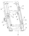
- Fig. 2
- eine perspektivische Ansicht der Anordnung von hinten, und
- Fig. 3
- eine perspektivische Ansicht der Anordnung von vorn.
- In der
Figur 1 ist ein Fahrzeug 10 in Form eines landwirtschaftlichen Traktors dargestellt, das sich auf einem Rahmen 12 aufbaut und durch vordere, lenkbare Räder 14 und antreibbare, rückwärtige Räder 16 auf dem Boden abstützt. Der Bedienerarbeitsplatz befindet sich in einer Kabine 18. Am rückwärtigen Ende des Rahmens ist eine Dreipunktkupplung 20 angeordnet, die sich aus zwei nebeneinander angeordneten Unterlenkern 22 und einem Oberlenker 28 zusammensetzt. Die Unterlenker 22 sind durch Hydraulikzylinder 26 höhenverstellbar. Der Oberlenker 28 ist durch einen Hydraulikzylinder 24 längenveränderbar ist. Durch Verstellung der Hydraulikzylinder 26 kann die Arbeitshöhe eines Arbeitsgerätes 36 verändert werden. Durch Verstellung der Länge des Oberlenkers 28, die anstelle durch den Hydraulikzylinder 24 auch rein mechanisch durch den Bediener von Hand mittels geeigneter Schraubspindeln erfolgen könnte, ist der Neigungswinkel des Arbeitsgeräts 36 verstellbar. Am rückwärtigen Ende der Unterlenker 22 sind in an sich bekannter Weise Unterlenker-Koppelpunkte 30 in Form von sich nach oben erstreckenden Fanghaken (oder beliebiger anderer Koppelpunkte, z. B. Koppelaugen, wie sie in der DIN ISO 730-1 Landmaschinen und Traktoren - Heck-Dreipunktanbau - Teil 1: Kategorien 1, 2, 3 und 4 beschrieben werden) angeordnet, während am rückwärtigen Ende des Oberlenkers 28 ein ebenfalls konventioneller Oberlenker-Koppelpunkt 32 vorgesehen ist. - An der Dreipunktkupplung 20 ist eine Anordnung 34 zur seitlich verstellbaren Anbringung eines landwirtschaftlichen Arbeitsgeräts 36 abnehmbar befestigt. Die Anordnung 34 umfasst ein rahmenförmiges erstes Element 38, das durch untere Laschen 40 und Bolzen 42 an den Unterlenker-Kopplungspunkten 30 der Unterlenker 22 und durch ein oberes Halterungselement 44 und einen Bolzen 44 am Oberlenker-Koppelpunkt 32 befestigt ist. Weiterhin umfasst die Anordnung 34 ein rahmenförmiges zweites Element 48, dessen quer zur Vorwärtsrichtung des Fahrzeugs gemessene Breite kleiner als die des ersten Elements 38 ist. Das zweite Element 48 stützt sich durch eine untere Halterung 50, die eine mit dem ersten Element 38 verbundene, an dessen Unterseite befestigte, stangenförmige Halterung 52 von unten und vorn umgreift, sowie eine obere Halterung 54, die eine mit dem ersten Element 38 verbundene, an dessen Oberseite befestigte, stangenförmige Halterung 56 von oben und vorn umgreift, am ersten Element 38 ab. Zwischen den Halterungen 52 und 56 einerseits und den Halterungen 50 und 54 andererseits könnten auch noch Wälzlager oder andere reibungsmindernde Elemente, wie Kunststoffschichten, eingebaut werden, um die Reibung zu vermindern.
- Das zweite Element 48 ist gegenüber dem ersten Element 38 mittels eines sich im oberen Bereich der Anordnung 34 zwischen den Elementen 38, 48 erstreckenden Aktors 58 in Form eines Hydraulikzylinders (vgl.
Figuren 2 und3 ) in seitlicher Richtung (d. h. horizontal und quer zur Vorwärtsrichtung des Fahrzeugs 10) verschiebbar. Dazu ist der Aktor 58 mit einer Steuerung 60 verbunden, die ihn basierend auf einer in einem Speicher der Steuerung 60 abgelegten Sollwegkarte, Positionsinformationen von einer auf dem Dach der Kabine 18 angebrachten Antenne 62 zum Empfang von Signalen von Satelliten eines globalen Positionierungssystems (z. B. GPS) und einem vorzugsweise im Gehäuse des Aktors 58 eingebauten Sensors (nicht gezeigt) zur Erfassung der Position des Aktors 58 und/oder einer am Arbeitsgerät 36 angebrachten Antenne 62 zum Empfang von Signalen von Satelliten eines globalen Positionierungssystems derart ansteuert, dass das Arbeitsgerät 36 entlang des Sollwegs bewegt wird. Die Lenkung des Fahrzeugs 10 kann ebenfalls selbsttätig durch die Steuerung 60 oder durch dessen Fahrer bewerkstelligt werden. Einzelheiten der Ansteuerung des Aktors 58 können den SchriftenUS 7 162 348 B2 undUS 7 460 942 B2 entnommen werden, deren Offenbarung durch Verweis mit in die vorliegenden Unterlagen aufgenommen wird. Die Information über die aktuelle Position des Fahrzeugs 10 und/oder des Arbeitsgeräts 36 könnte auch durch eine Kamera oder einen Laser-Scanner bereitgestellt werden, der das Feld vor dem Fahrzeug abtastet. Bei einer anderen Ausführungsform, die insbesondere bei Mähwerken sinnvoll ist, wird die Sollweginformation durch Lenksignale des Fahrzeugs definiert und die Positionssignale werden anhand des oben erwähnten, die Position des zweiten Elements gegenüber der ersten Element erfassenden Sensors (nicht gezeigt) erzeugt, um zu erreichen, dass möglichst wenig Überlappung und ungemähtes Material bei vorn und hinten am Fahrzeug angebrachten Mähwerken erzielt wird. Hierzu sei auf die Offenbarung derEP 1 321 027 A1 verwiesen, deren Offenbarung durch Verweis mit in die vorliegenden Unterlagen aufgenommen wird. Weiterhin kann die Steuerung 60 mittels der Hydraulikzylinder 26 und 24 auch die Arbeitshöhe des Arbeitsgeräts 36 kontrollieren, sei es ortsspezifisch anhand der Sollwegkarte oder nur im Vorgewende. - Das zweite Element 48 umfasst an seinem unteren Ende eine Schiene 66, an der Unterlenker-Koppelpunkte 68 lösbar und in seitlich verschiebbarer Weise angebracht sind, was durch die Schiene 66 ganz oder teilweise umschließende Befestigungselemente 84 (vgl.
Figur 2 ) erfolgt, da die Schiene 66 im Abstand vom zweiten Element 48 angebracht ist. Außerdem umfasst das zweite Element 48 an seinem oberen Ende einen oberen Kopplungspunkt 70. Das Arbeitsgerät 36 umfasst einen Rahmen 72 mit einem an seinem vorderen Bereich montierten, sich vertikal erstreckenden Tragrahmen 74. Der Tragrahmen 74 ist an seinem unteren Ende mit Streben 76 verbunden, die wiederum durch Bolzen 78 in die Unterlenker-Kopplungspunkte 68 eingreifen und sich daran abstützen. Weiterhin ist der Tragrahmen 74 an seinem oberen Ende mit einem Oberlenker 80 verbunden, der wiederum durch einen Bolzen 82 am oberen Kopplungspunkt 70 festgelegt ist. Anstelle des dargestellten Oberlenkers 80 mit fester Länge könnte auch ein manuell oder hydraulisch längenverstellbarer Oberlenker verwendet werden. - Nach alledem ist offensichtlich, dass die erfindungsgemäße Anordnung 34 zur seitlich verstellbaren Anbringung des Arbeitsgeräts 36 zwischen den Dreipunkt-Schnittstellen des Fahrzeugs 10 und des Arbeitsgeräts 36 eingefügt wird und eine automatische seitliche Verstellung des Arbeitsgeräts 36 gegenüber dem Fahrzeug 10 ermöglicht, um das Arbeitsgerät 36 auf einem Sollweg zu führen. Die Schiene 66 ermöglicht es jedoch auch, anstelle der Unterlenker-Kopplungspunkte 68 beliebige andere Befestigungsmittel für Arbeitsgeräte anzubringen, zum Beispiel ein Zugmaul, eine Kugelkopfkupplung, ein Zugpendel oder eine Ackerschiene (nicht gezeigt). Weiterhin hat die Rahmenform der Elemente 38, 48 den Vorteil, dass bei Bedarf eine Zapfwelle (nicht gezeigt) durch sie hindurchführbar ist, um ein antreibbares Arbeitsgerät damit anzutreiben.
Claims (9)
- Anordnung (34) zur seitlich verstellbaren Anbringung eines landwirtschaftlichen Arbeitsgeräts (36) an einem Fahrzeug (10), umfassend:ein erstes Element (38), das an einer Dreipunktkupplung (20) des Fahrzeugs (10) anbringbar ist,ein zweites Element (48), das mittels eines fremdkraftbetätigten Aktors (58) gegenüber dem ersten Element (38) in einer horizontalen und quer zur Vorwärtsrichtung verlaufenden Richtung bewegbar und an dem das Arbeitsgerät (36) anbringbar ist, wobei der Aktor (58) im Betrieb basierend auf Positionssignalen und einer Sollweginformation derart ansteuerbar ist, dass das zweite Element (48) mit dem Arbeitsgerät (36) entlang eines Sollwegs geführt wird,dadurch gekennzeichnet, dass das zweite Element (48) gegenüber dem ersten Element (38) in der horizontalen und quer zur Vorwärtsrichtung verlaufenden Richtung verschiebbar gelagert ist,und dass das Arbeitsgerät (36) am zweiten Element (48) lösbar anbringbar ist.
- Anordnung (34) nach Anspruch 1, dadurch gekennzeichnet, dass das zweite Element (48) zur Anbringung von unterschiedlichen Kupplungseinrichtungen von Arbeitsgeräten (36) ausgelegt ist.
- Anordnung (34) nach Anspruch 2, dadurch gekennzeichnet, dass das zweite Element (48) eine untere, sich horizontal und quer zur Vorwärtsrichtung erstreckende Schiene (66) umfasst, an der ein oder mehrere Unterlenker-Koppelpunkte (68) und/oder ein Zugmaul und/oder eine Kugelkopfkupplung und/oder ein Zugpendel und/oder eine Ackerschiene in seitlicher Richtung verstellbar anbringbar ist oder sind.
- Anordnung (34) nach Anspruch 2 oder 3, dadurch gekennzeichnet, dass das zweite Element (48) einen oberen Kopplungspunkt (70) umfasst, an dem ein Oberlenker (80) anbringbar ist.
- Anordnung (34) nach einem der Ansprüche 1 bis 4, dadurch gekennzeichnet, dass das erste Element (38) und das zweite Element (48) jeweils einen zumindest im Wesentlichen rechteckigen Rahmen umfassen, wobei das erste Element (38) breiter als das zweite Element (48) ist.
- Anordnung (34) nach Anspruch 5, dadurch gekennzeichnet, dass die Rahmen hinreichenden Platz für den Durchtritt einer Zapfwelle freilassen.
- Anordnung (34) nach einem der Ansprüche 1 bis 6, dadurch gekennzeichnet, dass eines der Elemente (38, 48) mit einem Abschnitt (50, 54) versehen ist, der eine Halterung (52, 56) des anderen Elements (48, 38) umgreift.
- Anordnung (34) nach einem der Ansprüche 1 bis 7, dadurch gekennzeichnet, dass die Sollweginformation eine in einem Speicher einer Steuerung (60) abgelegte Sollwegkarte ist und dass die Positionssignale anhand eines Signale von Satelliten empfangenden Positionsbestimmungssystems oder durch eine Kamera oder einen das Feld vor dem Fahrzeug abtastenden Laser-Scanner erzeugt werden.
- Anordnung (34) nach einem der Ansprüche 1 bis 7, dadurch gekennzeichnet, dass die Sollweginformation durch Lenksignale des Fahrzeugs definiert ist und dass die Positionssignale anhand eines die Position des zweiten Elements (48) gegenüber der ersten Element (38) erfassenden Sensors erzeugt werden.
Applications Claiming Priority (1)
| Application Number | Priority Date | Filing Date | Title |
|---|---|---|---|
| DE102009028409A DE102009028409A1 (de) | 2009-08-10 | 2009-08-10 | Anordnung zur seitlich verstellbaren Anbringung eines landwirtschaftlichen Arbeitsgeräts an einem Fahrzeug |
Publications (3)
| Publication Number | Publication Date |
|---|---|
| EP2283719A2 true EP2283719A2 (de) | 2011-02-16 |
| EP2283719A3 EP2283719A3 (de) | 2011-05-04 |
| EP2283719B1 EP2283719B1 (de) | 2017-06-14 |
Family
ID=43332599
Family Applications (1)
| Application Number | Title | Priority Date | Filing Date |
|---|---|---|---|
| EP10170067.2A Active EP2283719B1 (de) | 2009-08-10 | 2010-07-20 | Anordnung zur seitlichen verstellbaren Anbringung eines landwirtschaftlichen Arbeitsgeräts an einem Fahrzeug |
Country Status (2)
| Country | Link |
|---|---|
| EP (1) | EP2283719B1 (de) |
| DE (1) | DE102009028409A1 (de) |
Cited By (19)
| Publication number | Priority date | Publication date | Assignee | Title |
|---|---|---|---|---|
| WO2016041547A1 (de) * | 2014-09-17 | 2016-03-24 | Jürgen Wagner | Zugfahrzeug und anhängevorrichtung für ein anbaugerät |
| EP3259970A1 (de) * | 2016-06-23 | 2017-12-27 | Solemat | Landwirtschaftliche werkzeughalterungsvorrichtung, die die einhaltung der reihen erleichtert, entsprechendes montageverfahren und entsprechendes landwirtschaftliches system |
| US9913422B2 (en) | 2015-06-22 | 2018-03-13 | Laforge Llc | Apparatus to reliably locate pull-type implement according to a localizing signal |
| EP3311640A1 (de) | 2016-10-20 | 2018-04-25 | Franz Aunkofer | Anhängevorrichtung für ein landwirtschaftliches zugfahrzeug und ein verfahren zu deren betrieb |
| IT201600112532A1 (it) * | 2016-11-08 | 2018-05-08 | Orsi Group S R L | apparecchiatura per macchine agricole e similari |
| DE102017110653B3 (de) | 2017-05-16 | 2018-08-09 | Jürgen Wagner | Anbauvorrichtung zur Kopplung eines landwirtschaftlichen Arbeitsgerätes an ein Zugfahrzeug |
| WO2018172458A1 (fr) * | 2017-03-24 | 2018-09-27 | Hubert Defrancq | Dispositif d'attelage pour engin agricole |
| EP3453236A1 (de) * | 2017-09-07 | 2019-03-13 | Aebi Schmidt Deutschland GmbH | Anbauplatteneinheit |
| US20190289789A1 (en) * | 2018-03-21 | 2019-09-26 | Johnny E. Grice | Tree branch and brush cutting attachment |
| EP3439450A4 (de) * | 2016-04-07 | 2019-12-25 | Mollick, Peter J. | System zur verbindung einer vorrichtung an einer mobilen maschine |
| EP3685647A1 (de) | 2019-01-25 | 2020-07-29 | Deere & Company | System und verfahren zur steuerung eines mit einem fahrzeug verbundenen geräts |
| EP3685649A1 (de) | 2019-01-25 | 2020-07-29 | Deere & Company | System und verfahren zur steuerung eines mit einem fahrzeug verbundenen gerätes |
| DE102019202852A1 (de) | 2019-01-25 | 2020-07-30 | Deere & Company | System und Verfahren zur Steuerung eines Arbeitsgeräts |
| EP3735810A1 (de) * | 2019-05-07 | 2020-11-11 | Deere & Company | Kopplungsvorrichtung für einen kraftheber |
| EP3756433A1 (de) | 2019-03-15 | 2020-12-30 | Deere & Company | System zur kontrolle eines mit einem fahrzeug verbundenen arbeitsgeräts |
| US10966363B2 (en) * | 2018-01-19 | 2021-04-06 | Peter Mollick | Connector system for mobile machinery |
| EP3740056A4 (de) * | 2018-01-19 | 2021-10-13 | Mollick, Peter J. | Verbindersystem für mobile maschinen |
| EP4032378A1 (de) * | 2021-01-22 | 2022-07-27 | Thyregod A/S | Zwischenreihenkultivator und verfahren zur kultivierung zwischen reihen von kulturpflanzen |
| FR3131504A1 (fr) * | 2022-01-04 | 2023-07-07 | Pascal MAZUIR | Dispositif et système d’interface entre un attelage de tracteur agricole et un outil |
Families Citing this family (8)
| Publication number | Priority date | Publication date | Assignee | Title |
|---|---|---|---|---|
| DE102010041885A1 (de) | 2010-10-01 | 2012-04-05 | Deere & Company | Kombination aus einem Zugfahrzeug und einem Gerät |
| DE102011054630A1 (de) | 2011-10-20 | 2013-04-25 | Claas Agrosystems GmbH | Visualisierungseinrichtung |
| DE102011085244A1 (de) | 2011-10-26 | 2013-05-02 | Deere & Company | Anordnung zur selbsttätigen Lenkung einer Kombination aus einem selbstfahrenden Fahrzeug und einem Gerät zur Feldbearbeitung |
| US9374939B2 (en) | 2014-08-29 | 2016-06-28 | Deere & Company | System and method for steering of an implement on sloped ground |
| DE102016212201A1 (de) | 2016-07-05 | 2018-01-11 | Deere & Company | Anordnung zur selbsttätigen Führung eines Gerätes |
| DE102017214354B3 (de) | 2017-04-24 | 2018-09-27 | Deere & Company | Landwirtschaftliches Arbeitsfahrzeug mit Bodeneingriffsmitteln zur Übertragung von Querkräften |
| DE102020100871A1 (de) * | 2020-01-15 | 2021-07-15 | Claas Saulgau Gmbh | Adapter eines landwirtschaftlichen Anbaugeräts und landwirtschaftliches Anbaugerät |
| DE102021125360A1 (de) | 2021-09-30 | 2023-03-30 | Horsch Leeb Application Systems Gmbh | Vorrichtung und Verfahren zur Bestimmung einer Lenkvorgabe für eine landwirtschaftliche Maschine |
Citations (4)
| Publication number | Priority date | Publication date | Assignee | Title |
|---|---|---|---|---|
| DE8233213U1 (de) | 1983-05-11 | Kunsler, Josef, 8190 Wolfratshausen | Anbaugerät für einen Kleinschlepper | |
| EP1321027A1 (de) | 2001-12-20 | 2003-06-25 | Kverneland ASA | Mäher mit großer Breite |
| US7162348B2 (en) | 2002-12-11 | 2007-01-09 | Hemisphere Gps Llc | Articulated equipment position control system and method |
| US7460942B2 (en) | 2001-04-09 | 2008-12-02 | Hemisphere Gps Llc | Soil cultivation implement control apparatus and method |
Family Cites Families (3)
| Publication number | Priority date | Publication date | Assignee | Title |
|---|---|---|---|---|
| AUPO135296A0 (en) * | 1996-08-01 | 1996-08-22 | Great Western Corporation Pty Ltd | Agricultural cultivator |
| DE10114091A1 (de) * | 2001-03-22 | 2002-09-26 | Deere & Co | Steuervorrichtung für eine Fahrzeuganbauschnittstelle |
| US7054731B1 (en) * | 2003-08-29 | 2006-05-30 | Trimble Navigation Limited | Farm implement guidance method and apparatus |
-
2009
- 2009-08-10 DE DE102009028409A patent/DE102009028409A1/de not_active Withdrawn
-
2010
- 2010-07-20 EP EP10170067.2A patent/EP2283719B1/de active Active
Patent Citations (4)
| Publication number | Priority date | Publication date | Assignee | Title |
|---|---|---|---|---|
| DE8233213U1 (de) | 1983-05-11 | Kunsler, Josef, 8190 Wolfratshausen | Anbaugerät für einen Kleinschlepper | |
| US7460942B2 (en) | 2001-04-09 | 2008-12-02 | Hemisphere Gps Llc | Soil cultivation implement control apparatus and method |
| EP1321027A1 (de) | 2001-12-20 | 2003-06-25 | Kverneland ASA | Mäher mit großer Breite |
| US7162348B2 (en) | 2002-12-11 | 2007-01-09 | Hemisphere Gps Llc | Articulated equipment position control system and method |
Cited By (32)
| Publication number | Priority date | Publication date | Assignee | Title |
|---|---|---|---|---|
| WO2016041547A1 (de) * | 2014-09-17 | 2016-03-24 | Jürgen Wagner | Zugfahrzeug und anhängevorrichtung für ein anbaugerät |
| US9913422B2 (en) | 2015-06-22 | 2018-03-13 | Laforge Llc | Apparatus to reliably locate pull-type implement according to a localizing signal |
| EP3439450A4 (de) * | 2016-04-07 | 2019-12-25 | Mollick, Peter J. | System zur verbindung einer vorrichtung an einer mobilen maschine |
| EP3259970A1 (de) * | 2016-06-23 | 2017-12-27 | Solemat | Landwirtschaftliche werkzeughalterungsvorrichtung, die die einhaltung der reihen erleichtert, entsprechendes montageverfahren und entsprechendes landwirtschaftliches system |
| FR3052955A1 (fr) * | 2016-06-23 | 2017-12-29 | Solemat | Dispositif porte-outil agricole facilitant la prise de rang, processus d'installation et systeme agricole associes |
| EP3311640A1 (de) | 2016-10-20 | 2018-04-25 | Franz Aunkofer | Anhängevorrichtung für ein landwirtschaftliches zugfahrzeug und ein verfahren zu deren betrieb |
| IT201600112532A1 (it) * | 2016-11-08 | 2018-05-08 | Orsi Group S R L | apparecchiatura per macchine agricole e similari |
| EP3318114A1 (de) * | 2016-11-08 | 2018-05-09 | ORSI Group S.R.L. | Vorrichtung zur unterstützung eines landwirtschaftlichen arbeitskopfs |
| US11277954B2 (en) | 2017-03-24 | 2022-03-22 | Hubert Defrancq | Hitch device for agricultural vehicle |
| WO2018172458A1 (fr) * | 2017-03-24 | 2018-09-27 | Hubert Defrancq | Dispositif d'attelage pour engin agricole |
| FR3064152A1 (fr) * | 2017-03-24 | 2018-09-28 | Hubert Defrancq | Dispositif d'attelage pour engin agricole |
| AU2018238533B2 (en) * | 2017-03-24 | 2023-05-18 | Hubert Defrancq | Hitch device for agricultural vehicle |
| EP3403477A1 (de) | 2017-05-16 | 2018-11-21 | Jürgen Wagner | Anbauvorrichtung zur kopplung eines landwirtschaftlichen arbeitsgerätes an ein zugfahrzeug |
| DE102017110653B3 (de) | 2017-05-16 | 2018-08-09 | Jürgen Wagner | Anbauvorrichtung zur Kopplung eines landwirtschaftlichen Arbeitsgerätes an ein Zugfahrzeug |
| EP3453236A1 (de) * | 2017-09-07 | 2019-03-13 | Aebi Schmidt Deutschland GmbH | Anbauplatteneinheit |
| EP3740056A4 (de) * | 2018-01-19 | 2021-10-13 | Mollick, Peter J. | Verbindersystem für mobile maschinen |
| AU2019210127B2 (en) * | 2018-01-19 | 2022-10-27 | Peter Mollick | Connector system for mobile machinery |
| US10966363B2 (en) * | 2018-01-19 | 2021-04-06 | Peter Mollick | Connector system for mobile machinery |
| US20190289789A1 (en) * | 2018-03-21 | 2019-09-26 | Johnny E. Grice | Tree branch and brush cutting attachment |
| US11564356B2 (en) * | 2018-03-21 | 2023-01-31 | Johnny E. Grice | Tree branch and brush cutting attachment |
| DE102019202852A1 (de) | 2019-01-25 | 2020-07-30 | Deere & Company | System und Verfahren zur Steuerung eines Arbeitsgeräts |
| US11324158B2 (en) | 2019-01-25 | 2022-05-10 | Deere & Company | System and method for controlling an implement connected to a vehicle |
| US11388852B2 (en) | 2019-01-25 | 2022-07-19 | Deere & Company | System and method for controlling an implement connected to a vehicle |
| EP3685649A1 (de) | 2019-01-25 | 2020-07-29 | Deere & Company | System und verfahren zur steuerung eines mit einem fahrzeug verbundenen gerätes |
| EP3685647A1 (de) | 2019-01-25 | 2020-07-29 | Deere & Company | System und verfahren zur steuerung eines mit einem fahrzeug verbundenen geräts |
| EP3756433A1 (de) | 2019-03-15 | 2020-12-30 | Deere & Company | System zur kontrolle eines mit einem fahrzeug verbundenen arbeitsgeräts |
| US11470759B2 (en) | 2019-03-15 | 2022-10-18 | Deere & Company | System for controlling a working implement connected to a vehicle |
| EP3735810A1 (de) * | 2019-05-07 | 2020-11-11 | Deere & Company | Kopplungsvorrichtung für einen kraftheber |
| US11558992B2 (en) | 2019-05-07 | 2023-01-24 | Deere & Company | Coupling device for a power lift |
| EP4032378A1 (de) * | 2021-01-22 | 2022-07-27 | Thyregod A/S | Zwischenreihenkultivator und verfahren zur kultivierung zwischen reihen von kulturpflanzen |
| FR3131504A1 (fr) * | 2022-01-04 | 2023-07-07 | Pascal MAZUIR | Dispositif et système d’interface entre un attelage de tracteur agricole et un outil |
| WO2023131754A1 (fr) * | 2022-01-04 | 2023-07-13 | Pm Diffusions 01 | Dispositif et système d'interface entre un attelage de tracteur agricole et un outil |
Also Published As
| Publication number | Publication date |
|---|---|
| EP2283719B1 (de) | 2017-06-14 |
| EP2283719A3 (de) | 2011-05-04 |
| DE102009028409A1 (de) | 2011-02-17 |
Similar Documents
| Publication | Publication Date | Title |
|---|---|---|
| EP2283719B1 (de) | Anordnung zur seitlichen verstellbaren Anbringung eines landwirtschaftlichen Arbeitsgeräts an einem Fahrzeug | |
| EP2621257B1 (de) | Kombination aus einem zugfahrzeug und einem gerät | |
| EP2586282B1 (de) | Anordnung zur selbsttätigen Lenkung einer Kombination aus einem selbstfahrenden Fahrzeug und einem Gerät zur Feldbearbeitung | |
| WO2016041547A1 (de) | Zugfahrzeug und anhängevorrichtung für ein anbaugerät | |
| EP0533041B1 (de) | Führungsvorrichtung für Unterlänker und landwirtschaftliches Fahrzeug | |
| EP3903549B1 (de) | Bodenbearbeitungsmaschine, vorzugsweise landwirtschaftlicher hackstriegel und verfahren zum einstellen einer vorspannkraft an einem hackstriegel | |
| EP1932416A1 (de) | Vorrichtung mit einer ersten und einer zweiten Arbeitseinheit | |
| EP3689118A1 (de) | Landwirtschaftliches arbeitsgerät, deichselvorrichtung und zugfahrzeug-arbeitsgerät-kombination | |
| DE102016117237A1 (de) | Verfahren zum mechanischen Koppeln eines Anbaugerätes mit einem Zugfahrzeug oder einer Anhängevorrichtung | |
| EP3772265A1 (de) | Hackvorrichtung | |
| DE102009047181B4 (de) | Landwirtschaftliches Bodenbearbeitungsgerät zur Befestigung an einem Fahrzeug | |
| EP3756433B1 (de) | System zur kontrolle eines mit einem fahrzeug verbundenen arbeitsgeräts | |
| DE19951080A1 (de) | Selbstfahrendes landwirtschaftliches Fahrzeug | |
| DE102017214354B3 (de) | Landwirtschaftliches Arbeitsfahrzeug mit Bodeneingriffsmitteln zur Übertragung von Querkräften | |
| EP3791707A1 (de) | Vorrichtung zum bodennahen bearbeiten von pflanzlichem material und verfahren zum bodennahen bearbeiten von pflanzlichem material | |
| DE3523632A1 (de) | Pflug | |
| DE3216950C2 (de) | ||
| EP2949198A1 (de) | Vorrichtung zur Bearbeitung von Bodenflächen und Halte-Vorrichtung als Bausatz für eine solche Vorrichtung | |
| DE102019205321A1 (de) | Verfahren zur Steuerung des Betriebs eines Anbaugerätes | |
| DE2116583A1 (de) | Vorrichtung zum seitlichen Anhängen einer landwirtschaftlichen Erntemaschine | |
| AT519979B1 (de) | Dreipunktkupplung | |
| EP3735810A1 (de) | Kopplungsvorrichtung für einen kraftheber | |
| EP3818797B1 (de) | Landwirtschaftliches arbeitsgerät und -gerätekombination | |
| DE4236166A1 (de) | Anschlußvorrichtung | |
| DE202015104793U1 (de) | Zu einer Fahrspur eines Zugfahrzeugs seitlich versetzt einsetzbare Bodenarbeitsvorrichtung |
Legal Events
| Date | Code | Title | Description |
|---|---|---|---|
| PUAI | Public reference made under article 153(3) epc to a published international application that has entered the european phase |
Free format text: ORIGINAL CODE: 0009012 |
|
| AK | Designated contracting states |
Kind code of ref document: A2 Designated state(s): AL AT BE BG CH CY CZ DE DK EE ES FI FR GB GR HR HU IE IS IT LI LT LU LV MC MK MT NL NO PL PT RO SE SI SK SM TR |
|
| AX | Request for extension of the european patent |
Extension state: BA ME RS |
|
| PUAL | Search report despatched |
Free format text: ORIGINAL CODE: 0009013 |
|
| AK | Designated contracting states |
Kind code of ref document: A3 Designated state(s): AL AT BE BG CH CY CZ DE DK EE ES FI FR GB GR HR HU IE IS IT LI LT LU LV MC MK MT NL NO PL PT RO SE SI SK SM TR |
|
| AX | Request for extension of the european patent |
Extension state: BA ME RS |
|
| 17P | Request for examination filed |
Effective date: 20111104 |
|
| GRAP | Despatch of communication of intention to grant a patent |
Free format text: ORIGINAL CODE: EPIDOSNIGR1 |
|
| INTG | Intention to grant announced |
Effective date: 20170202 |
|
| GRAS | Grant fee paid |
Free format text: ORIGINAL CODE: EPIDOSNIGR3 |
|
| GRAA | (expected) grant |
Free format text: ORIGINAL CODE: 0009210 |
|
| AK | Designated contracting states |
Kind code of ref document: B1 Designated state(s): AL AT BE BG CH CY CZ DE DK EE ES FI FR GB GR HR HU IE IS IT LI LT LU LV MC MK MT NL NO PL PT RO SE SI SK SM TR |
|
| REG | Reference to a national code |
Ref country code: GB Ref legal event code: FG4D Free format text: NOT ENGLISH |
|
| REG | Reference to a national code |
Ref country code: CH Ref legal event code: EP Ref country code: AT Ref legal event code: REF Ref document number: 900101 Country of ref document: AT Kind code of ref document: T Effective date: 20170615 |
|
| REG | Reference to a national code |
Ref country code: IE Ref legal event code: FG4D Free format text: LANGUAGE OF EP DOCUMENT: GERMAN |
|
| REG | Reference to a national code |
Ref country code: NL Ref legal event code: FP Ref country code: FR Ref legal event code: PLFP Year of fee payment: 8 |
|
| REG | Reference to a national code |
Ref country code: DE Ref legal event code: R096 Ref document number: 502010013731 Country of ref document: DE |
|
| REG | Reference to a national code |
Ref country code: LT Ref legal event code: MG4D |
|
| PG25 | Lapsed in a contracting state [announced via postgrant information from national office to epo] |
Ref country code: NO Free format text: LAPSE BECAUSE OF FAILURE TO SUBMIT A TRANSLATION OF THE DESCRIPTION OR TO PAY THE FEE WITHIN THE PRESCRIBED TIME-LIMIT Effective date: 20170914 Ref country code: ES Free format text: LAPSE BECAUSE OF FAILURE TO SUBMIT A TRANSLATION OF THE DESCRIPTION OR TO PAY THE FEE WITHIN THE PRESCRIBED TIME-LIMIT Effective date: 20170614 Ref country code: LT Free format text: LAPSE BECAUSE OF FAILURE TO SUBMIT A TRANSLATION OF THE DESCRIPTION OR TO PAY THE FEE WITHIN THE PRESCRIBED TIME-LIMIT Effective date: 20170614 Ref country code: HR Free format text: LAPSE BECAUSE OF FAILURE TO SUBMIT A TRANSLATION OF THE DESCRIPTION OR TO PAY THE FEE WITHIN THE PRESCRIBED TIME-LIMIT Effective date: 20170614 Ref country code: FI Free format text: LAPSE BECAUSE OF FAILURE TO SUBMIT A TRANSLATION OF THE DESCRIPTION OR TO PAY THE FEE WITHIN THE PRESCRIBED TIME-LIMIT Effective date: 20170614 Ref country code: GR Free format text: LAPSE BECAUSE OF FAILURE TO SUBMIT A TRANSLATION OF THE DESCRIPTION OR TO PAY THE FEE WITHIN THE PRESCRIBED TIME-LIMIT Effective date: 20170915 |
|
| PG25 | Lapsed in a contracting state [announced via postgrant information from national office to epo] |
Ref country code: LV Free format text: LAPSE BECAUSE OF FAILURE TO SUBMIT A TRANSLATION OF THE DESCRIPTION OR TO PAY THE FEE WITHIN THE PRESCRIBED TIME-LIMIT Effective date: 20170614 Ref country code: SE Free format text: LAPSE BECAUSE OF FAILURE TO SUBMIT A TRANSLATION OF THE DESCRIPTION OR TO PAY THE FEE WITHIN THE PRESCRIBED TIME-LIMIT Effective date: 20170614 Ref country code: BG Free format text: LAPSE BECAUSE OF FAILURE TO SUBMIT A TRANSLATION OF THE DESCRIPTION OR TO PAY THE FEE WITHIN THE PRESCRIBED TIME-LIMIT Effective date: 20170914 |
|
| PG25 | Lapsed in a contracting state [announced via postgrant information from national office to epo] |
Ref country code: CZ Free format text: LAPSE BECAUSE OF FAILURE TO SUBMIT A TRANSLATION OF THE DESCRIPTION OR TO PAY THE FEE WITHIN THE PRESCRIBED TIME-LIMIT Effective date: 20170614 Ref country code: RO Free format text: LAPSE BECAUSE OF FAILURE TO SUBMIT A TRANSLATION OF THE DESCRIPTION OR TO PAY THE FEE WITHIN THE PRESCRIBED TIME-LIMIT Effective date: 20170614 Ref country code: EE Free format text: LAPSE BECAUSE OF FAILURE TO SUBMIT A TRANSLATION OF THE DESCRIPTION OR TO PAY THE FEE WITHIN THE PRESCRIBED TIME-LIMIT Effective date: 20170614 Ref country code: SK Free format text: LAPSE BECAUSE OF FAILURE TO SUBMIT A TRANSLATION OF THE DESCRIPTION OR TO PAY THE FEE WITHIN THE PRESCRIBED TIME-LIMIT Effective date: 20170614 |
|
| PG25 | Lapsed in a contracting state [announced via postgrant information from national office to epo] |
Ref country code: PL Free format text: LAPSE BECAUSE OF FAILURE TO SUBMIT A TRANSLATION OF THE DESCRIPTION OR TO PAY THE FEE WITHIN THE PRESCRIBED TIME-LIMIT Effective date: 20170614 Ref country code: IT Free format text: LAPSE BECAUSE OF FAILURE TO SUBMIT A TRANSLATION OF THE DESCRIPTION OR TO PAY THE FEE WITHIN THE PRESCRIBED TIME-LIMIT Effective date: 20170614 Ref country code: SM Free format text: LAPSE BECAUSE OF FAILURE TO SUBMIT A TRANSLATION OF THE DESCRIPTION OR TO PAY THE FEE WITHIN THE PRESCRIBED TIME-LIMIT Effective date: 20170614 Ref country code: IS Free format text: LAPSE BECAUSE OF FAILURE TO SUBMIT A TRANSLATION OF THE DESCRIPTION OR TO PAY THE FEE WITHIN THE PRESCRIBED TIME-LIMIT Effective date: 20171014 |
|
| REG | Reference to a national code |
Ref country code: CH Ref legal event code: PL |
|
| REG | Reference to a national code |
Ref country code: DE Ref legal event code: R097 Ref document number: 502010013731 Country of ref document: DE |
|
| PG25 | Lapsed in a contracting state [announced via postgrant information from national office to epo] |
Ref country code: MC Free format text: LAPSE BECAUSE OF FAILURE TO SUBMIT A TRANSLATION OF THE DESCRIPTION OR TO PAY THE FEE WITHIN THE PRESCRIBED TIME-LIMIT Effective date: 20170614 |
|
| REG | Reference to a national code |
Ref country code: IE Ref legal event code: MM4A |
|
| PLBE | No opposition filed within time limit |
Free format text: ORIGINAL CODE: 0009261 |
|
| STAA | Information on the status of an ep patent application or granted ep patent |
Free format text: STATUS: NO OPPOSITION FILED WITHIN TIME LIMIT |
|
| PG25 | Lapsed in a contracting state [announced via postgrant information from national office to epo] |
Ref country code: CH Free format text: LAPSE BECAUSE OF NON-PAYMENT OF DUE FEES Effective date: 20170731 Ref country code: LI Free format text: LAPSE BECAUSE OF NON-PAYMENT OF DUE FEES Effective date: 20170731 Ref country code: DK Free format text: LAPSE BECAUSE OF FAILURE TO SUBMIT A TRANSLATION OF THE DESCRIPTION OR TO PAY THE FEE WITHIN THE PRESCRIBED TIME-LIMIT Effective date: 20170614 Ref country code: IE Free format text: LAPSE BECAUSE OF NON-PAYMENT OF DUE FEES Effective date: 20170720 |
|
| 26N | No opposition filed |
Effective date: 20180315 |
|
| REG | Reference to a national code |
Ref country code: BE Ref legal event code: MM Effective date: 20170731 |
|
| PG25 | Lapsed in a contracting state [announced via postgrant information from national office to epo] |
Ref country code: LU Free format text: LAPSE BECAUSE OF NON-PAYMENT OF DUE FEES Effective date: 20170720 |
|
| REG | Reference to a national code |
Ref country code: FR Ref legal event code: PLFP Year of fee payment: 9 |
|
| PG25 | Lapsed in a contracting state [announced via postgrant information from national office to epo] |
Ref country code: SI Free format text: LAPSE BECAUSE OF FAILURE TO SUBMIT A TRANSLATION OF THE DESCRIPTION OR TO PAY THE FEE WITHIN THE PRESCRIBED TIME-LIMIT Effective date: 20170614 Ref country code: BE Free format text: LAPSE BECAUSE OF NON-PAYMENT OF DUE FEES Effective date: 20170731 |
|
| REG | Reference to a national code |
Ref country code: AT Ref legal event code: MM01 Ref document number: 900101 Country of ref document: AT Kind code of ref document: T Effective date: 20170720 |
|
| PG25 | Lapsed in a contracting state [announced via postgrant information from national office to epo] |
Ref country code: MT Free format text: LAPSE BECAUSE OF FAILURE TO SUBMIT A TRANSLATION OF THE DESCRIPTION OR TO PAY THE FEE WITHIN THE PRESCRIBED TIME-LIMIT Effective date: 20170614 |
|
| PG25 | Lapsed in a contracting state [announced via postgrant information from national office to epo] |
Ref country code: AT Free format text: LAPSE BECAUSE OF NON-PAYMENT OF DUE FEES Effective date: 20170720 |
|
| PG25 | Lapsed in a contracting state [announced via postgrant information from national office to epo] |
Ref country code: HU Free format text: LAPSE BECAUSE OF FAILURE TO SUBMIT A TRANSLATION OF THE DESCRIPTION OR TO PAY THE FEE WITHIN THE PRESCRIBED TIME-LIMIT; INVALID AB INITIO Effective date: 20100720 |
|
| PG25 | Lapsed in a contracting state [announced via postgrant information from national office to epo] |
Ref country code: CY Free format text: LAPSE BECAUSE OF NON-PAYMENT OF DUE FEES Effective date: 20170614 |
|
| PG25 | Lapsed in a contracting state [announced via postgrant information from national office to epo] |
Ref country code: MK Free format text: LAPSE BECAUSE OF FAILURE TO SUBMIT A TRANSLATION OF THE DESCRIPTION OR TO PAY THE FEE WITHIN THE PRESCRIBED TIME-LIMIT Effective date: 20170614 |
|
| PG25 | Lapsed in a contracting state [announced via postgrant information from national office to epo] |
Ref country code: TR Free format text: LAPSE BECAUSE OF FAILURE TO SUBMIT A TRANSLATION OF THE DESCRIPTION OR TO PAY THE FEE WITHIN THE PRESCRIBED TIME-LIMIT Effective date: 20170614 |
|
| PG25 | Lapsed in a contracting state [announced via postgrant information from national office to epo] |
Ref country code: PT Free format text: LAPSE BECAUSE OF FAILURE TO SUBMIT A TRANSLATION OF THE DESCRIPTION OR TO PAY THE FEE WITHIN THE PRESCRIBED TIME-LIMIT Effective date: 20170614 |
|
| PG25 | Lapsed in a contracting state [announced via postgrant information from national office to epo] |
Ref country code: AL Free format text: LAPSE BECAUSE OF FAILURE TO SUBMIT A TRANSLATION OF THE DESCRIPTION OR TO PAY THE FEE WITHIN THE PRESCRIBED TIME-LIMIT Effective date: 20170614 |
|
| PGFP | Annual fee paid to national office [announced via postgrant information from national office to epo] |
Ref country code: NL Payment date: 20210726 Year of fee payment: 12 |
|
| REG | Reference to a national code |
Ref country code: DE Ref legal event code: R084 Ref document number: 502010013731 Country of ref document: DE |
|
| REG | Reference to a national code |
Ref country code: NL Ref legal event code: MM Effective date: 20220801 |
|
| PG25 | Lapsed in a contracting state [announced via postgrant information from national office to epo] |
Ref country code: NL Free format text: LAPSE BECAUSE OF NON-PAYMENT OF DUE FEES Effective date: 20220801 |
|
| PGFP | Annual fee paid to national office [announced via postgrant information from national office to epo] |
Ref country code: GB Payment date: 20230727 Year of fee payment: 14 |
|
| PGFP | Annual fee paid to national office [announced via postgrant information from national office to epo] |
Ref country code: FR Payment date: 20230725 Year of fee payment: 14 Ref country code: DE Payment date: 20230621 Year of fee payment: 14 |