EP2283185B9 - Stabilisierungsbewehrung zur verwendung in bewehrten bodenkonstruktionen - Google Patents
Stabilisierungsbewehrung zur verwendung in bewehrten bodenkonstruktionen Download PDFInfo
- Publication number
- EP2283185B9 EP2283185B9 EP09742240.6A EP09742240A EP2283185B9 EP 2283185 B9 EP2283185 B9 EP 2283185B9 EP 09742240 A EP09742240 A EP 09742240A EP 2283185 B9 EP2283185 B9 EP 2283185B9
- Authority
- EP
- European Patent Office
- Prior art keywords
- longitudinal
- parts
- reinforcement
- transverse
- facing
- Prior art date
- Legal status (The legal status is an assumption and is not a legal conclusion. Google has not performed a legal analysis and makes no representation as to the accuracy of the status listed.)
- Not-in-force
Links
- 230000002787 reinforcement Effects 0.000 title claims description 108
- 239000002689 soil Substances 0.000 title claims description 18
- 230000000087 stabilizing effect Effects 0.000 title description 34
- 239000000463 material Substances 0.000 claims description 25
- 229910052751 metal Inorganic materials 0.000 claims description 12
- 239000002184 metal Substances 0.000 claims description 12
- 238000010276 construction Methods 0.000 claims description 6
- 238000005304 joining Methods 0.000 claims description 6
- 229910000831 Steel Inorganic materials 0.000 claims description 5
- 239000010959 steel Substances 0.000 claims description 5
- 230000003019 stabilising effect Effects 0.000 claims 12
- 238000000926 separation method Methods 0.000 claims 5
- 238000005452 bending Methods 0.000 description 8
- 238000000034 method Methods 0.000 description 8
- 230000006641 stabilisation Effects 0.000 description 8
- 238000004873 anchoring Methods 0.000 description 5
- 238000006073 displacement reaction Methods 0.000 description 4
- 238000004519 manufacturing process Methods 0.000 description 4
- 238000011105 stabilization Methods 0.000 description 4
- 229910001335 Galvanized steel Inorganic materials 0.000 description 3
- 230000007797 corrosion Effects 0.000 description 3
- 238000005260 corrosion Methods 0.000 description 3
- 239000008397 galvanized steel Substances 0.000 description 3
- 230000003014 reinforcing effect Effects 0.000 description 3
- 238000005253 cladding Methods 0.000 description 2
- 238000005246 galvanizing Methods 0.000 description 2
- 238000003466 welding Methods 0.000 description 2
- 229910000611 Zinc aluminium Inorganic materials 0.000 description 1
- 229910045601 alloy Inorganic materials 0.000 description 1
- 239000000956 alloy Substances 0.000 description 1
- HXFVOUUOTHJFPX-UHFFFAOYSA-N alumane;zinc Chemical compound [AlH3].[Zn] HXFVOUUOTHJFPX-UHFFFAOYSA-N 0.000 description 1
- 239000000835 fiber Substances 0.000 description 1
- 239000004746 geotextile Substances 0.000 description 1
- 150000002500 ions Chemical class 0.000 description 1
- 210000000056 organ Anatomy 0.000 description 1
- 229920000728 polyester Polymers 0.000 description 1
- 239000011253 protective coating Substances 0.000 description 1
- 229920002994 synthetic fiber Polymers 0.000 description 1
Images


Classifications
-
- E—FIXED CONSTRUCTIONS
- E02—HYDRAULIC ENGINEERING; FOUNDATIONS; SOIL SHIFTING
- E02D—FOUNDATIONS; EXCAVATIONS; EMBANKMENTS; UNDERGROUND OR UNDERWATER STRUCTURES
- E02D29/00—Independent underground or underwater structures; Retaining walls
- E02D29/02—Retaining or protecting walls
- E02D29/0225—Retaining or protecting walls comprising retention means in the backfill
- E02D29/0241—Retaining or protecting walls comprising retention means in the backfill the retention means being reinforced earth elements
-
- Y—GENERAL TAGGING OF NEW TECHNOLOGICAL DEVELOPMENTS; GENERAL TAGGING OF CROSS-SECTIONAL TECHNOLOGIES SPANNING OVER SEVERAL SECTIONS OF THE IPC; TECHNICAL SUBJECTS COVERED BY FORMER USPC CROSS-REFERENCE ART COLLECTIONS [XRACs] AND DIGESTS
- Y10—TECHNICAL SUBJECTS COVERED BY FORMER USPC
- Y10T—TECHNICAL SUBJECTS COVERED BY FORMER US CLASSIFICATION
- Y10T29/00—Metal working
- Y10T29/49—Method of mechanical manufacture
- Y10T29/49826—Assembling or joining
Definitions
- the present invention relates to a stabilizing reinforcement for use in reinforced soil structures, as well as the use of such a reinforcement for the construction of structures in reinforced soil.
- a reinforced soil structure combines a compacted embankment, a siding and reinforcements connected or not to the facing.
- the facing is for example made from prefabricated concrete elements, in the form of slabs or blocks, juxtaposed to cover the front face of the structure.
- a book thus produced is known in particular under the commercial reference Terra Class of Terre Armée Internationale.
- the facing may also be made from a grid, in particular consisting of metal rods welded together.
- a siding may comprise a geotextile and may be vegetated.
- a book thus produced is known in particular under the commercial reference Terra Trel of Terre Armée Internationale.
- reinforcements may be used: metal, for example comprising rods of galvanized steel, of synthetic material such as stabilizing strips for example based on polyester fibers.
- the reinforcements are placed in the ground with a density depending on the stresses that may be exerted on the structure, the thrust forces of the ground being taken up by the friction soil-reinforcements.
- the stabilizing reinforcements are attached to the facing and / or to a wall located at a distance from the facing.
- Stabilizing reinforcements for use in reinforced soil structures include longitudinal, elongated portions. Their length is of the order of magnitude of the meter. They can reach several meters in length.
- the longitudinal portions of the reinforcements may be arranged one by one in the ground, or may be assembled together by different means. The width and the thickness of such longitudinal parts are of the order of a centimeter, and generally do not exceed ten centimeters.
- the longitudinal portions may be arranged substantially perpendicularly to the facing or be arranged at an angle to the facing. In the latter case, there are generally longitudinal portions on either side of an axis perpendicular to the facing. In general, the longitudinal portions of the reinforcements are arranged in a substantially horizontal plane.
- An example where the longitudinal parts are at an angle to the facing is the modular reinforcement arranged in a triangular network according to FR-A-2233857 . This document represents the prior art closest to the reinforcement of claim 1.
- Metal stabilizing reinforcements are often considered advantageous in terms of price and generally consist of metal rods welded together to form for example ladders or trellis.
- a ladder-shaped reinforcement generally consists of two substantially parallel metal rods, each constituting a longitudinal portion, and transverse rods which connect the longitudinal rods together to provide rigidity to the assembly.
- transverse is meant a portion of a reinforcement that connects two longitudinal portions to each other. Such parts are for example made of rods. As a result, the transverse portions are arranged to be substantially parallel or angled with respect to a facing.
- transverse rods of the ladder-shaped reinforcements are generally arranged perpendicularly to the longitudinal rods. They may, however, be inclined relative to the longitudinal rods.
- transverse rods are generally distributed over the entire length of the longitudinal rods and in particular spaced regularly.
- the spacing between two transverse rods is of the order of a few tens of centimeters for a usual ladder-shaped reinforcement.
- one end of the ladder-shaped reinforcement comprises a fastening means to the facing, in particular hooks formed or arranged on one end of the longitudinal rods, or a flat and pierced piece connecting the ends of two longitudinal rods, where the pierced portion of said part is intended to receive means of connection with the facing.
- the metal rods used for such reinforcements are generally steel rods. They are often cylindrical and their diameter is generally of the order of a centimeter. These rods are advantageous to use because their cost is very moderate. However, the medium in which they are disposed is corrosive, especially because of the pH of the soils and ions they include, which may further vary with time, rainfall or other parameters.
- Such ladder-shaped stabilizing reinforcement has several disadvantages. It is often necessary to move it, or even to transport it from a remote production site, before setting it up on a soil reinforcement site. The associated transportation costs can be high because such reinforcements are bulky.
- welds are sometimes weak points of a ladder-shaped reinforcement. It seems indeed that protection by galvanizing is often imperfect in the weld zones, thus potentially allowing localized corrosion and significantly reducing the robustness of the whole.
- One solution may be to increase the safety coefficients for a given structure, for example by increasing the density of reinforcements. Such a solution is nevertheless expensive and unsatisfactory.
- An object of the present invention is to overcome the aforementioned drawbacks and in particular to provide a reinforcement free of risks associated with corrosion of welds between longitudinal and transverse parts.
- the invention thus proposes a stabilizing reinforcement defined precisely in claim 1.
- transverse moving parts transverse parts may be displaced relative to at least one longitudinal portion. This displacement may correspond to a translation, in which case the transverse part moves as a whole with respect to the two longitudinal parts. This displacement can also be a rotation. In some cases of rotation, a point, in particular an end of a transverse part may remain fixed relative to a longitudinal portion, while the remainder of this transverse portion moves relative to the two longitudinal portions. It is also possible to combine a translation and a rotation.
- the displacement of a transverse portion relative to a longitudinal portion may be effected from the zone of the reinforcement where the two longitudinal portions are farthest from each other to the zone where these longitudinal portions are the closest, especially to the point where the axes of these two longitudinal portions overlap, that is to say in the direction of the interior of the embankment to the facing when the reinforcement is disposed in a structure.
- angular stops to limit the angular spacing of two longitudinal portions any means for limiting the angular spacing of the two longitudinal portions, in particular by limiting a distance between two points of two separate longitudinal parts.
- a stabilization reinforcement according to the invention it is possible to avoid welding the longitudinal parts to the transverse parts. As a result, such a reinforcement no longer presents a risk of preferential corrosion.
- the combination of a non-zero angular difference ⁇ + ⁇ between two longitudinal portions and the use of transverse portions comprising angular stops makes it possible to ensure the stiffening of the reinforcement when said longitudinal parts come into contact with said abutments of the transverse parts.
- the invention also relates to a structure in reinforced soil comprising a facing along a front face of the structure and / or a wall delimiting a backfill, wherein said backfill is stabilized by at least one stabilizing reinforcement according to the present invention.
- the invention also relates to such a reinforced soil structure where the angles ⁇ and ⁇ are substantially equal to each other, the angles ⁇ and ⁇ each measuring the angular difference between an orthogonal axis facing and one of the two longitudinal portions.
- the structure thus produced is preferably obtained with a plurality of said stabilizing reinforcements, each comprising two longitudinal parts, where these different reinforcements are spaced from each other, without them touching or being interconnected by something else. only fill material.
- these various reinforcements are connected to the siding at intervals regular, both in a horizontal plane and in a plane parallel to the facing. In this way, a reinforced structure is obtained efficiently and easily.
- the invention also relates to a method of constructing a structure in reinforced soil, in which is placed at a distance from a wall, a facing along a front face of the work delimiting a volume to be backfilled, there are reinforcements in a zone of said volume, embankment material is brought into said volume and the backfill material is compacted, where said reinforcements consist at least partly of stabilizing reinforcements according to the present invention.
- the stabilizing reinforcements are arranged spaced from each other, without them touching or being interconnected by anything other than backfill material.
- each longitudinal portion there are two longitudinal parts connecting one end of each longitudinal portion to the facing or the wall in a substantially horizontal plane, there is a plurality of elements comprising a transverse part and moving said parts transverse to the longitudinal portions, for example in translation and / or in rotation, so as to delimit the angular spacing ⁇ + ⁇ .
- each longitudinal portion there are two longitudinal parts connecting one end of each longitudinal portion to the facing or the wall in a substantially horizontal plane, there is an element comprising a plurality of transverse parts in continuity of material, so as to delimit the angular spacing ⁇ + ⁇ .
- two longitudinal parts are arranged by connecting one end of each longitudinal part to the facing or to the wall in a substantially horizontal plane, the one or both longitudinal part (s) being connected (s) in continuity of material with a transverse portion, the transverse portion is rotated relative to said longitudinal portion so as to define the angular spacing ⁇ + ⁇ .
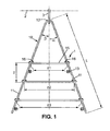
- the figure 1 illustrates a schematic top view, where a stabilizing reinforcement 1, according to the invention, is connected to a facing (not shown) at a point along a line 2.
- a facing is usually made up of a plurality of facing elements, for example formed by a concrete block cast in a mold.
- the cladding element may comprise one or more anchoring pieces, for example hook or ring, embedded in the concrete and extending beyond the concrete block according to line 2.
- line 2 is generally substantially parallel to the front face of the facing.
- the reinforcement 1 is connected to an anchor piece of a facing element via a hook 3.
- the reinforcement shown generally extends substantially horizontally and rests on backfill material.
- the reinforcement 1 comprises two longitudinal parts 11, connected in continuity of material by a bend 12 to form a part 10 having substantially the shape of a V, and a plurality of transverse portions 15. Without limitation, three transverse parts are shown .
- the transverse parts are of regularly increasing length, d 1 , d 2 , d 3 . Each of their ends is provided with a hook 16 whose end is directed towards the inside of the transverse parts
- the two longitudinal parts are spaced angularly from a non-zero angle ⁇ + ⁇ , in this case of the order of 20 ° to 30 °.
- the angles ⁇ and ⁇ are substantially equal, where the angles ⁇ and ⁇ each measure the angular difference between an axis orthogonal to the line 2 of the cladding attachment locations and the longitudinal portion 11 located to the right of the figure and respectively the longitudinal portion 11 to the left of the figure.
- the piece 10 may for example be formed on a site by bending a rod length 2 L in the middle to obtain the two longitudinal portions 11 of length L, spaced an angle ⁇ + ⁇ .
- the transverse portions 15 may for example be formed on a site by bending inward the ends of a rod to form the hooks 16.
- the transverse portions 15 are arranged so that the hooks 16 of each end of each part transverse grip a longitudinal portion 11 of the part 10 and thus form angular stops to limit the angular spacing of the two longitudinal portions 11.
- Such a reinforcement 1 can be obtained by first placing the workpiece 10 on a fill, then sliding the transverse portions 15 in the direction from the bend 12 to the opposite ends of the longitudinal portions 11 until the hooks 16 are abutting said longitudinal portions 11.
- the three transverse portions 15 are then spaced from each other by a value E and prevent the longitudinal portions 11 from departing from more than d 1 , d 2 , d 3 respectively at the points of contact.
- a hook 3 can be placed in the bend 12 of the piece 10 and hooked to an anchoring piece on the line 2.
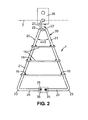
- the figure 2 illustrates a top view of another stabilizing reinforcement 1 according to the invention.
- the reinforcement comprises two parts 20 each comprising a longitudinal portion 21 with each a hook 22 at one end.
- the hooks 22 are arranged in a ring 27 which is connected to an anchoring plate 28.
- This plate may be integral with a facing element or may be attached thereto.
- the two longitudinal portions 21 are separated by an angle ⁇ + ⁇ and their angular spacing is limited by transverse portions 15 of the type of those described above.
- the ends of the longitudinal portions 21, opposite those where the hooks 22 are arranged are interconnected. They may for example be interconnected by parts 24 extending them. These portions 24 are substantially parallel to the transverse portions 15 and connected in continuity of material by a bend 23 to the longitudinal portions 21.
- the parts 24 may for example be connected together by means of threaded ends 25 held by an inverted-threaded piece 26.
- FIG. 3 A variant of the embodiment of the figure 2 is represented in figure 3 wherein a stabilizing reinforcement according to the invention comprises two parts 30 each comprising a longitudinal portion 31 and a head 32 at one end.
- the heads 32 are disposed in one of the holes of an anchoring plate 28 of the type previously described.
- the two anchor plates are spaced apart and the heads 32 of the parts 30 are thus connected to the facing at remote points. It is thus possible to make a stabilization reinforcement wider than those previously described.
- the figure 4 illustrates a top view of a stabilizing reinforcement 1 according to the invention which is a variant of the embodiment shown in FIG. figure 2 .
- the reinforcement comprises two parts 40 and 44 each comprising a longitudinal portion 41 and 45 respectively, each having a hook 42 at one end disposed in a ring 27 connected to an anchor plate 28.
- the longitudinal portion 45 of the piece 44 is straight.
- the longitudinal part 41 of the part 40 comprises housings 43.
- This longitudinal portion can be made from the same rod by bending to form the dwellings 43 and the hook 42. It is also possible to obtain a piece of this type from a straight rod to which is reported, for example by screwing, welding or any other suitable means, housing.
- the transverse portions 46 comprise at each end heads 47, 48, for example obtained by bending at 90 ° of a rod, or by relating a head end 47, 48 by any other means known to those skilled in the art.
- One of the heads 47 of each of the transverse portions 46 is disposed in a housing 43 of the longitudinal portion 41.
- the heads 47 and the housings 43 are, in the example shown, made so that the heads 47 can move only in rotation relative to their axis in the housings 43.
- the reinforcement 1 represented in figure 4 can be obtained by placing on a backfill parts 40 and 44, by hooking these parts by their hooks 42 to a ring 27 connected to the facing, by separating the two parts 40 and 44 from the desired angle ⁇ + ⁇ , by introducing the heads 47 in the housings 43 of the workpiece 40, and rotating the transverse portions 46 about the axis of the heads 47 until the heads 48 of said transverse parts come to contact the workpiece 44 to limit the angular spacing between the longitudinal portions 41 and 45.
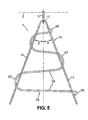
- the figure 5 illustrates a top view of a stabilizing reinforcement 1 according to yet another embodiment.
- This reinforcement comprises two longitudinal portions 11, connected in continuity of material by a bend 12 to form a part 10 and a part 55 comprising a plurality of transverse portions 56 connected in continuity of material by bends 57. It is quite possible to replace the part 10 including the transverse parts here represented by pieces 20 or 30 as represented respectively in figures 2 and 3 .
- the part 55 comprises at these ends hooks 58, 59.
- Such a part 55 can be made by bending a rod.
- the reinforcement 1 represented in figure 5 can be obtained by sliding the piece 55 on the piece 10 from the elbow 12, for example by introducing the longitudinal portions 11 in the loops formed by a bend 57 and the two transverse portions 56 attached thereto.
- the piece 55 thus passes above and below the piece 10.
- the hooks 58, 59 form angular stops to limit the angular spacing ⁇ + ⁇ of the longitudinal portions 11.
- the bends 57 also constitute angular stops to limit the angular spacing of the two longitudinal portions.
- the figure 6 illustrates a stabilizing reinforcement 1 according to the prior art constituted by a continuous part 60.
- This reinforcement comprises two longitudinal parts 61, connected in continuity of material by a bend 62 and two transverse parts 65, 66 each connected in continuity so as to a elbow respectively 63, 64 with the longitudinal parts 61.
- a hook 67, 68 is disposed at the other end of each transverse part 65, 66.
- Such a reinforcement can be obtained by bending a single rod.
- the transverse portions 65, 66 can be displaced, for example by rotation about the axis of the elbows 63, 64, by slightly deforming these bends, so as to bring the hooks 67, 68 into contact with the longitudinal portions 61 and thus form angular stops to limit the angular spacing of the two longitudinal portions.
- the figure 7 illustrates another embodiment of a stabilizing reinforcement 1 according to the invention which can also be obtained by bending a single rod and forming a continuous piece 70.
- This reinforcement comprises two longitudinal portions 71, 73 connected in continuity of material by a bend 72 and a plurality of transverse portions 75, 77.
- the transverse portion 75 is connected in continuity of material to the longitudinal portion 73 by a bend 74.
- the other transverse portions 77 are connected in continuity of material between them by bends 76, and one of them is connected in continuity of material by a bend 76 to the transverse portion 75.
- a hook 78 is disposed at the end of the part transverse 77 farthest from the transverse portion 75.
- the hook 78 forms an angular abutment making it possible to limit the angular spacing of the two longitudinal parts 71, 73 as well as the bends 76 which are drawn so that their internal part comes into contact with the longitudinal parts 71, 73 when the hook 78 is in contact with the longitudinal part 73.
- the displacement of the transverse portions 15, 46, 56, 75, 77 is effected within a perimeter defined by the two longitudinal portions 11, 21, 31 , 41, 44, 71, 73, their point of intersection or the line joining the two ends closest to the two longitudinal parts and the line joining the two other ends furthest from the two longitudinal parts.
- the perimeter is defined by the two longitudinal portions, respectively 11, 21, 41 and 44, 11, 61 which meet at a point of intersection, respectively located in the bend 12, at the overlap of the hooks 22, the hooks 42, in the bends 12, 62, 72 and the line joining the other two most designated ends of these two longitudinal portions respectively 11, 21, 41 and 44, 11, 61.
- the perimeter is defined by the two longitudinal portions 31, the line passing through their two ends closest together passing through the heads 32 and the line joining the other two ends furthest from these two longitudinal portions 31.
- the invention also relates to a method of constructing a structure in reinforced soil.
- the figure 8 illustrates such a method.
- a compacted embankment 81 in which stabilizing reinforcements 1 according to the invention are distributed, is delimited on the front side of the structure by a facing 84 constituted by juxtaposing prefabricated elements 85, and on the rear side by the ground 83. against which is erected the retaining wall.
- the stabilizing reinforcements 1 can be connected to the facing elements 85, and extend for a distance within the embankment 81. These stabilizing reinforcements 1 contribute to reinforce the soil located in a reinforced zone Z at the back of the siding 84.
- the material of the embankment 81 has a high resistance because it is reinforced by the stabilizing reinforcements 1. It is thus able to withstand the shear stresses that are exerted due to tensile forces This reinforcing area Z must naturally have a thickness sufficient to hold the facing 84 firmly.
- the stabilizing reinforcements are generally connected by connecting means, in particular hooks or rings, to the back of the facing elements 85.
- the stabilizing reinforcements 1 are arranged in horizontal planes superposed alternately on the height of the structure.
- the stabilizing reinforcements 1 are attached to the wall 83.
- the attachment to the wall can be done by nailing an anchoring element in the wall 83 which for example is bonded a ring. Then there is for example a hook which connects said ring and a stabilizing reinforcement.
- a reinforcement of the type of the reinforcement represented in FIG. figure 2 by a hook located along the parts 24 or in a bend 23, a reinforcement shown in figure 6 by a hook located in a bend 63 or 64, or a reinforcement represented in figure 7 by a hook located in the elbow 74. It is also conceivable to connect a reinforcement whose end of longitudinal portion 11, 31, 41, 44, 71 is free by adding at this end a hook or a ring to introduce a connecting element to the wall.
- the reinforcements according to the invention can be used and to attach them to a wall only.
- the narrowest part of the stabilizing reinforcements is directed towards the wall 83 to which it is connected.
- line 2 represents the line of anchorage points at the wall.
- the plates 28 may be connected to the wall by nailing.
- attachment reinforcements a reinforcing layer being attached to the wall and the reinforcing layer located above and / or below being attached to a facing.
- the projections on a horizontal plane of the reinforcements attached to the wall and those attached to the facing have an overlapping zone.
Landscapes
- Engineering & Computer Science (AREA)
- Environmental & Geological Engineering (AREA)
- Life Sciences & Earth Sciences (AREA)
- General Life Sciences & Earth Sciences (AREA)
- Mining & Mineral Resources (AREA)
- Paleontology (AREA)
- Civil Engineering (AREA)
- General Engineering & Computer Science (AREA)
- Structural Engineering (AREA)
- Pit Excavations, Shoring, Fill Or Stabilisation Of Slopes (AREA)
- Bridges Or Land Bridges (AREA)
- Consolidation Of Soil By Introduction Of Solidifying Substances Into Soil (AREA)
- Bulkheads Adapted To Foundation Construction (AREA)
- Piles And Underground Anchors (AREA)
- Reinforcement Elements For Buildings (AREA)
Claims (15)
Priority Applications (1)
| Application Number | Priority Date | Filing Date | Title |
|---|---|---|---|
| PL09742240T PL2283185T3 (pl) | 2008-04-08 | 2009-04-03 | Wzmocnienie stabilizacyjne do zastosowania w budowlach ziemnych wzmocnionych |
Applications Claiming Priority (2)
| Application Number | Priority Date | Filing Date | Title |
|---|---|---|---|
| FR0852340A FR2929628B1 (fr) | 2008-04-08 | 2008-04-08 | Renfort de stabilisation destine a etre utilise dans des ouvrages en sol renforce |
| PCT/FR2009/050573 WO2009136042A1 (fr) | 2008-04-08 | 2009-04-03 | Renfort de stabilisation destine a etre utilise dans des ouvrages en sol renforce |
Publications (3)
| Publication Number | Publication Date |
|---|---|
| EP2283185A1 EP2283185A1 (de) | 2011-02-16 |
| EP2283185B1 EP2283185B1 (de) | 2012-03-14 |
| EP2283185B9 true EP2283185B9 (de) | 2013-05-29 |
Family
ID=39870467
Family Applications (1)
| Application Number | Title | Priority Date | Filing Date |
|---|---|---|---|
| EP09742240.6A Not-in-force EP2283185B9 (de) | 2008-04-08 | 2009-04-03 | Stabilisierungsbewehrung zur verwendung in bewehrten bodenkonstruktionen |
Country Status (10)
| Country | Link |
|---|---|
| US (1) | US20110058904A1 (de) |
| EP (1) | EP2283185B9 (de) |
| JP (1) | JP5337864B2 (de) |
| AR (1) | AR073161A1 (de) |
| AT (1) | ATE549462T1 (de) |
| CL (1) | CL2009000847A1 (de) |
| ES (1) | ES2383953T3 (de) |
| FR (1) | FR2929628B1 (de) |
| PL (1) | PL2283185T3 (de) |
| WO (1) | WO2009136042A1 (de) |
Families Citing this family (3)
| Publication number | Priority date | Publication date | Assignee | Title |
|---|---|---|---|---|
| WO2011161493A1 (en) * | 2010-06-24 | 2011-12-29 | Terre Armee Internationale | Reinforced soil structure |
| FR3088349B1 (fr) | 2018-11-09 | 2021-01-15 | Terre Armee Int | Dispositif pour la contention d’elements granulaires |
| CN115262622B (zh) * | 2022-08-05 | 2023-10-27 | 新疆建筑科学研究院(有限责任公司) | 一种加筋挡土墙结构 |
Family Cites Families (24)
| Publication number | Priority date | Publication date | Assignee | Title |
|---|---|---|---|---|
| US1762343A (en) * | 1925-12-14 | 1930-06-10 | Munster Andreas | Retaining wall |
| US1739108A (en) * | 1928-03-13 | 1929-12-10 | Shore Line Builders Inc | Bulkhead-wall construction |
| FR2233857A5 (en) * | 1973-06-14 | 1975-01-10 | Maymont Paul | Temporary retaining or stabilising wall - has front panels anchored by a chain link mesh embedded in the soil |
| GB8602783D0 (en) * | 1986-02-05 | 1986-03-12 | Vidal H | Stabilised earth structures |
| GB8727420D0 (en) * | 1987-11-23 | 1987-12-23 | Vidal H | Earth structures |
| CH676015A5 (de) * | 1988-05-16 | 1990-11-30 | Hermann Claus | |
| US5807030A (en) * | 1993-03-31 | 1998-09-15 | The Reinforced Earth Company | Stabilizing elements for mechanically stabilized earthen structure |
| US5624211A (en) * | 1993-03-31 | 1997-04-29 | Societe Civile Des Brevets Henri C. Vidal | Modular block retaining wall construction and components |
| US6079908A (en) * | 1993-03-31 | 2000-06-27 | Societe Civile Des Brevets Henri Vidal | Stabilizing elements for mechanically stabilized earthen structure and mechanically stabilized earthen structure |
| US5507599A (en) * | 1993-03-31 | 1996-04-16 | Societe Civile Des Brevets Henri C. Vidal | Modular block retaining wall construction and components |
| GB9313095D0 (en) * | 1993-06-24 | 1993-08-11 | Vidal Henri Brevets | Earth structures |
| SG52467A1 (en) * | 1993-08-30 | 1998-09-28 | Reinforced Earth Co | Earthen work with wire mesh facing |
| US5669737A (en) * | 1995-07-27 | 1997-09-23 | Equilbec; Michel | Wall retention system |
| US20020031406A1 (en) * | 1995-12-01 | 2002-03-14 | Societe Civile Des Brevets Henri Vidal | Earth structures |
| IL132583A0 (en) * | 1997-04-28 | 2001-03-19 | Ecoflex Au Pty Ltd | Retaining wall system |
| US6675547B1 (en) * | 1999-07-30 | 2004-01-13 | Joseph Golcheh | Method for forming a head wall from an anchor pile and reinforcing member for said anchor pile structure |
| US6517293B2 (en) * | 2000-10-16 | 2003-02-11 | Thomas P. Taylor | Anchor grid connection element |
| US6854236B2 (en) * | 2001-10-11 | 2005-02-15 | Allan Block Corporation | Reinforcing system for stackable retaining wall units |
| FR2860811A1 (fr) * | 2003-10-13 | 2005-04-15 | Freyssinet Int Stup | Ouvrage en sol renforce et procede pour sa construction |
| US6857823B1 (en) * | 2003-11-28 | 2005-02-22 | William K. Hilfiker | Earthen retaining wall having flat soil reinforcing mats which may be variably spaced |
| KR100660356B1 (ko) * | 2004-10-19 | 2006-12-21 | 이정수 | 조립식 보강토 옹벽 지지용 띠형 섬유보강재의 시공방법및 이 시공방법에 사용되는 띠형 섬유보강재 |
| KR100865465B1 (ko) * | 2007-05-22 | 2008-10-28 | 신혜승 | 압출 성형 스트립 보강재를 이용한 블록식 옹벽 축조시스템 |
| US20090126372A1 (en) * | 2007-11-16 | 2009-05-21 | Solomon Aladja Faka | Intermittent De-Icing During Continuous Regasification of a Cryogenic Fluid Using Ambient Air |
| US7722296B1 (en) * | 2009-01-14 | 2010-05-25 | T&B Structual Systems, Llc | Retaining wall soil reinforcing connector and method |
-
2008
- 2008-04-08 FR FR0852340A patent/FR2929628B1/fr not_active Expired - Fee Related
-
2009
- 2009-04-03 JP JP2011503473A patent/JP5337864B2/ja not_active Expired - Fee Related
- 2009-04-03 ES ES09742240T patent/ES2383953T3/es active Active
- 2009-04-03 PL PL09742240T patent/PL2283185T3/pl unknown
- 2009-04-03 US US12/936,882 patent/US20110058904A1/en not_active Abandoned
- 2009-04-03 EP EP09742240.6A patent/EP2283185B9/de not_active Not-in-force
- 2009-04-03 AT AT09742240T patent/ATE549462T1/de active
- 2009-04-03 WO PCT/FR2009/050573 patent/WO2009136042A1/fr not_active Ceased
- 2009-04-07 AR ARP090101234A patent/AR073161A1/es unknown
- 2009-04-08 CL CL2009000847A patent/CL2009000847A1/es unknown
Also Published As
| Publication number | Publication date |
|---|---|
| WO2009136042A1 (fr) | 2009-11-12 |
| US20110058904A1 (en) | 2011-03-10 |
| AR073161A1 (es) | 2010-10-20 |
| FR2929628B1 (fr) | 2012-11-23 |
| ATE549462T1 (de) | 2012-03-15 |
| JP2011516765A (ja) | 2011-05-26 |
| EP2283185A1 (de) | 2011-02-16 |
| CL2009000847A1 (es) | 2010-06-11 |
| JP5337864B2 (ja) | 2013-11-06 |
| EP2283185B1 (de) | 2012-03-14 |
| PL2283185T3 (pl) | 2012-08-31 |
| ES2383953T3 (es) | 2012-06-27 |
| FR2929628A1 (fr) | 2009-10-09 |
Similar Documents
| Publication | Publication Date | Title |
|---|---|---|
| EP2352884B1 (de) | Verstärkte bodenstruktur und verkleidungselemente zu ihrer konstruktion | |
| EP0081402B1 (de) | Verfahren zur Herstellung von hohlen Elementen wie etwa Leitungen, Silos oder Bunkern | |
| FR2922234A1 (fr) | Bande de stabilisation souple destinee a etre utilisee dans des ouvrages en sol renforce | |
| EP2691578B1 (de) | Bewehrte erde | |
| EP2550406B1 (de) | Rückhaltewand mit bewehrter erde | |
| EP0244890B1 (de) | Verfahren zur Herstellung von hohlen Elementen, wie etwa Leitungen, Silos oder Bunker und Elemente, hergestellt durch dieses Verfahren | |
| EP2283185B9 (de) | Stabilisierungsbewehrung zur verwendung in bewehrten bodenkonstruktionen | |
| EP2456924B1 (de) | Verbindungsglied bei stützwand mit bewehrter erde, stützwand und verfahren zur errichtung solch einer stützwand. | |
| EP2050879B1 (de) | Stabilisierungsstreifen für den Einsatz in Tiefbauten zur Verstärkung | |
| EP1662050B1 (de) | Bewehrtes Erdbauwerk und Vorderflächenelemente für dessen Bau | |
| EP3877591A1 (de) | Vorrichtung zur aufnahme von körnigen elementen | |
| FR2721988A1 (fr) | Conduite de circulation de fluide | |
| EP1806474B1 (de) | Verfahren zum Reparieren der Verkleidung einer Galerie | |
| EP1222340A1 (de) | Durchlässige schalungsplatte | |
| FR2706498A1 (fr) | Procédé de réalisation d'un ouvrage d'art voûté sous remblai, aménageant un passage. | |
| FR2913035A1 (fr) | Ouvrage comprenant un parement dresse devant une paroi et des moyens d'attache par friction qui s'etendent entre la paroi et le parement a l'interieur d'un remblai, et procede de construction | |
| FR2921943A1 (fr) | Assemblage de renforts en geomateriau pour ouvrage en sol renforce, ouvrage et procede associes | |
| FR2849145A1 (fr) | Procede de realisation d'une conduite de transport de fluide | |
| FR2816647A1 (fr) | Parement pour ouvrage en terre renforcee |
Legal Events
| Date | Code | Title | Description |
|---|---|---|---|
| PUAI | Public reference made under article 153(3) epc to a published international application that has entered the european phase |
Free format text: ORIGINAL CODE: 0009012 |
|
| 17P | Request for examination filed |
Effective date: 20101028 |
|
| AK | Designated contracting states |
Kind code of ref document: A1 Designated state(s): AT BE BG CH CY CZ DE DK EE ES FI FR GB GR HR HU IE IS IT LI LT LU LV MC MK MT NL NO PL PT RO SE SI SK TR |
|
| AX | Request for extension of the european patent |
Extension state: AL BA RS |
|
| 17Q | First examination report despatched |
Effective date: 20110506 |
|
| DAX | Request for extension of the european patent (deleted) | ||
| GRAP | Despatch of communication of intention to grant a patent |
Free format text: ORIGINAL CODE: EPIDOSNIGR1 |
|
| GRAS | Grant fee paid |
Free format text: ORIGINAL CODE: EPIDOSNIGR3 |
|
| GRAA | (expected) grant |
Free format text: ORIGINAL CODE: 0009210 |
|
| AK | Designated contracting states |
Kind code of ref document: B1 Designated state(s): AT BE BG CH CY CZ DE DK EE ES FI FR GB GR HR HU IE IS IT LI LT LU LV MC MK MT NL NO PL PT RO SE SI SK TR |
|
| REG | Reference to a national code |
Ref country code: GB Ref legal event code: FG4D Free format text: NOT ENGLISH |
|
| REG | Reference to a national code |
Ref country code: AT Ref legal event code: REF Ref document number: 549462 Country of ref document: AT Kind code of ref document: T Effective date: 20120315 Ref country code: CH Ref legal event code: EP |
|
| REG | Reference to a national code |
Ref country code: IE Ref legal event code: FG4D Free format text: LANGUAGE OF EP DOCUMENT: FRENCH |
|
| REG | Reference to a national code |
Ref country code: DE Ref legal event code: R096 Ref document number: 602009005917 Country of ref document: DE Effective date: 20120516 |
|
| REG | Reference to a national code |
Ref country code: ES Ref legal event code: FG2A Ref document number: 2383953 Country of ref document: ES Kind code of ref document: T3 Effective date: 20120627 |
|
| REG | Reference to a national code |
Ref country code: NL Ref legal event code: VDEP Effective date: 20120314 |
|
| PG25 | Lapsed in a contracting state [announced via postgrant information from national office to epo] |
Ref country code: NO Free format text: LAPSE BECAUSE OF FAILURE TO SUBMIT A TRANSLATION OF THE DESCRIPTION OR TO PAY THE FEE WITHIN THE PRESCRIBED TIME-LIMIT Effective date: 20120614 Ref country code: HR Free format text: LAPSE BECAUSE OF FAILURE TO SUBMIT A TRANSLATION OF THE DESCRIPTION OR TO PAY THE FEE WITHIN THE PRESCRIBED TIME-LIMIT Effective date: 20120314 Ref country code: LT Free format text: LAPSE BECAUSE OF FAILURE TO SUBMIT A TRANSLATION OF THE DESCRIPTION OR TO PAY THE FEE WITHIN THE PRESCRIBED TIME-LIMIT Effective date: 20120314 |
|
| LTIE | Lt: invalidation of european patent or patent extension |
Effective date: 20120314 |
|
| PG25 | Lapsed in a contracting state [announced via postgrant information from national office to epo] |
Ref country code: FI Free format text: LAPSE BECAUSE OF FAILURE TO SUBMIT A TRANSLATION OF THE DESCRIPTION OR TO PAY THE FEE WITHIN THE PRESCRIBED TIME-LIMIT Effective date: 20120314 Ref country code: GR Free format text: LAPSE BECAUSE OF FAILURE TO SUBMIT A TRANSLATION OF THE DESCRIPTION OR TO PAY THE FEE WITHIN THE PRESCRIBED TIME-LIMIT Effective date: 20120615 Ref country code: LV Free format text: LAPSE BECAUSE OF FAILURE TO SUBMIT A TRANSLATION OF THE DESCRIPTION OR TO PAY THE FEE WITHIN THE PRESCRIBED TIME-LIMIT Effective date: 20120314 |
|
| REG | Reference to a national code |
Ref country code: PL Ref legal event code: T3 |
|
| REG | Reference to a national code |
Ref country code: AT Ref legal event code: MK05 Ref document number: 549462 Country of ref document: AT Kind code of ref document: T Effective date: 20120314 |
|
| PG25 | Lapsed in a contracting state [announced via postgrant information from national office to epo] |
Ref country code: CY Free format text: LAPSE BECAUSE OF FAILURE TO SUBMIT A TRANSLATION OF THE DESCRIPTION OR TO PAY THE FEE WITHIN THE PRESCRIBED TIME-LIMIT Effective date: 20120314 |
|
| BERE | Be: lapsed |
Owner name: TERRE ARMEE INTERNATIONALE Effective date: 20120430 |
|
| PG25 | Lapsed in a contracting state [announced via postgrant information from national office to epo] |
Ref country code: IS Free format text: LAPSE BECAUSE OF FAILURE TO SUBMIT A TRANSLATION OF THE DESCRIPTION OR TO PAY THE FEE WITHIN THE PRESCRIBED TIME-LIMIT Effective date: 20120714 Ref country code: EE Free format text: LAPSE BECAUSE OF FAILURE TO SUBMIT A TRANSLATION OF THE DESCRIPTION OR TO PAY THE FEE WITHIN THE PRESCRIBED TIME-LIMIT Effective date: 20120314 Ref country code: RO Free format text: LAPSE BECAUSE OF FAILURE TO SUBMIT A TRANSLATION OF THE DESCRIPTION OR TO PAY THE FEE WITHIN THE PRESCRIBED TIME-LIMIT Effective date: 20120314 Ref country code: CZ Free format text: LAPSE BECAUSE OF FAILURE TO SUBMIT A TRANSLATION OF THE DESCRIPTION OR TO PAY THE FEE WITHIN THE PRESCRIBED TIME-LIMIT Effective date: 20120314 Ref country code: SI Free format text: LAPSE BECAUSE OF FAILURE TO SUBMIT A TRANSLATION OF THE DESCRIPTION OR TO PAY THE FEE WITHIN THE PRESCRIBED TIME-LIMIT Effective date: 20120314 Ref country code: SE Free format text: LAPSE BECAUSE OF FAILURE TO SUBMIT A TRANSLATION OF THE DESCRIPTION OR TO PAY THE FEE WITHIN THE PRESCRIBED TIME-LIMIT Effective date: 20120314 |
|
| PG25 | Lapsed in a contracting state [announced via postgrant information from national office to epo] |
Ref country code: SK Free format text: LAPSE BECAUSE OF FAILURE TO SUBMIT A TRANSLATION OF THE DESCRIPTION OR TO PAY THE FEE WITHIN THE PRESCRIBED TIME-LIMIT Effective date: 20120314 Ref country code: PT Free format text: LAPSE BECAUSE OF FAILURE TO SUBMIT A TRANSLATION OF THE DESCRIPTION OR TO PAY THE FEE WITHIN THE PRESCRIBED TIME-LIMIT Effective date: 20120716 Ref country code: MC Free format text: LAPSE BECAUSE OF NON-PAYMENT OF DUE FEES Effective date: 20120430 |
|
| REG | Reference to a national code |
Ref country code: IE Ref legal event code: MM4A |
|
| PLBE | No opposition filed within time limit |
Free format text: ORIGINAL CODE: 0009261 |
|
| STAA | Information on the status of an ep patent application or granted ep patent |
Free format text: STATUS: NO OPPOSITION FILED WITHIN TIME LIMIT |
|
| PG25 | Lapsed in a contracting state [announced via postgrant information from national office to epo] |
Ref country code: DK Free format text: LAPSE BECAUSE OF FAILURE TO SUBMIT A TRANSLATION OF THE DESCRIPTION OR TO PAY THE FEE WITHIN THE PRESCRIBED TIME-LIMIT Effective date: 20120314 Ref country code: AT Free format text: LAPSE BECAUSE OF FAILURE TO SUBMIT A TRANSLATION OF THE DESCRIPTION OR TO PAY THE FEE WITHIN THE PRESCRIBED TIME-LIMIT Effective date: 20120314 Ref country code: BE Free format text: LAPSE BECAUSE OF NON-PAYMENT OF DUE FEES Effective date: 20120430 Ref country code: NL Free format text: LAPSE BECAUSE OF FAILURE TO SUBMIT A TRANSLATION OF THE DESCRIPTION OR TO PAY THE FEE WITHIN THE PRESCRIBED TIME-LIMIT Effective date: 20120314 Ref country code: IE Free format text: LAPSE BECAUSE OF NON-PAYMENT OF DUE FEES Effective date: 20120403 |
|
| 26N | No opposition filed |
Effective date: 20121217 |
|
| PG25 | Lapsed in a contracting state [announced via postgrant information from national office to epo] |
Ref country code: MK Free format text: LAPSE BECAUSE OF FAILURE TO SUBMIT A TRANSLATION OF THE DESCRIPTION OR TO PAY THE FEE WITHIN THE PRESCRIBED TIME-LIMIT Effective date: 20120314 |
|
| REG | Reference to a national code |
Ref country code: DE Ref legal event code: R097 Ref document number: 602009005917 Country of ref document: DE Effective date: 20121217 |
|
| PG25 | Lapsed in a contracting state [announced via postgrant information from national office to epo] |
Ref country code: BG Free format text: LAPSE BECAUSE OF FAILURE TO SUBMIT A TRANSLATION OF THE DESCRIPTION OR TO PAY THE FEE WITHIN THE PRESCRIBED TIME-LIMIT Effective date: 20120614 Ref country code: MT Free format text: LAPSE BECAUSE OF FAILURE TO SUBMIT A TRANSLATION OF THE DESCRIPTION OR TO PAY THE FEE WITHIN THE PRESCRIBED TIME-LIMIT Effective date: 20120314 |
|
| PGFP | Annual fee paid to national office [announced via postgrant information from national office to epo] |
Ref country code: TR Payment date: 20130403 Year of fee payment: 5 |
|
| REG | Reference to a national code |
Ref country code: CH Ref legal event code: PL |
|
| PG25 | Lapsed in a contracting state [announced via postgrant information from national office to epo] |
Ref country code: CH Free format text: LAPSE BECAUSE OF NON-PAYMENT OF DUE FEES Effective date: 20130430 Ref country code: LI Free format text: LAPSE BECAUSE OF NON-PAYMENT OF DUE FEES Effective date: 20130430 |
|
| PG25 | Lapsed in a contracting state [announced via postgrant information from national office to epo] |
Ref country code: TR Free format text: LAPSE BECAUSE OF NON-PAYMENT OF DUE FEES Effective date: 20120403 Ref country code: LU Free format text: LAPSE BECAUSE OF NON-PAYMENT OF DUE FEES Effective date: 20120403 |
|
| PGFP | Annual fee paid to national office [announced via postgrant information from national office to epo] |
Ref country code: PL Payment date: 20140331 Year of fee payment: 6 |
|
| PGFP | Annual fee paid to national office [announced via postgrant information from national office to epo] |
Ref country code: GB Payment date: 20140327 Year of fee payment: 6 |
|
| PG25 | Lapsed in a contracting state [announced via postgrant information from national office to epo] |
Ref country code: HU Free format text: LAPSE BECAUSE OF FAILURE TO SUBMIT A TRANSLATION OF THE DESCRIPTION OR TO PAY THE FEE WITHIN THE PRESCRIBED TIME-LIMIT Effective date: 20090403 |
|
| PGFP | Annual fee paid to national office [announced via postgrant information from national office to epo] |
Ref country code: IT Payment date: 20140324 Year of fee payment: 6 Ref country code: FR Payment date: 20140422 Year of fee payment: 6 Ref country code: ES Payment date: 20140404 Year of fee payment: 6 Ref country code: DE Payment date: 20140321 Year of fee payment: 6 |
|
| REG | Reference to a national code |
Ref country code: FR Ref legal event code: CA Effective date: 20150112 |
|
| REG | Reference to a national code |
Ref country code: DE Ref legal event code: R119 Ref document number: 602009005917 Country of ref document: DE |
|
| GBPC | Gb: european patent ceased through non-payment of renewal fee |
Effective date: 20150403 |
|
| PG25 | Lapsed in a contracting state [announced via postgrant information from national office to epo] |
Ref country code: DE Free format text: LAPSE BECAUSE OF NON-PAYMENT OF DUE FEES Effective date: 20151103 Ref country code: GB Free format text: LAPSE BECAUSE OF NON-PAYMENT OF DUE FEES Effective date: 20150403 Ref country code: IT Free format text: LAPSE BECAUSE OF NON-PAYMENT OF DUE FEES Effective date: 20150403 |
|
| REG | Reference to a national code |
Ref country code: FR Ref legal event code: ST Effective date: 20151231 |
|
| PG25 | Lapsed in a contracting state [announced via postgrant information from national office to epo] |
Ref country code: FR Free format text: LAPSE BECAUSE OF NON-PAYMENT OF DUE FEES Effective date: 20150430 |
|
| PG25 | Lapsed in a contracting state [announced via postgrant information from national office to epo] |
Ref country code: PL Free format text: LAPSE BECAUSE OF NON-PAYMENT OF DUE FEES Effective date: 20150403 |
|
| PG25 | Lapsed in a contracting state [announced via postgrant information from national office to epo] |
Ref country code: ES Free format text: LAPSE BECAUSE OF NON-PAYMENT OF DUE FEES Effective date: 20150404 |
|
| REG | Reference to a national code |
Ref country code: ES Ref legal event code: FD2A Effective date: 20180703 |
|
| PG25 | Lapsed in a contracting state [announced via postgrant information from national office to epo] |
Ref country code: TR Free format text: LAPSE BECAUSE OF NON-PAYMENT OF DUE FEES Effective date: 20150403 |