EP2282948B1 - Packaging and display tray formed from interlocked blanks - Google Patents
Packaging and display tray formed from interlocked blanks Download PDFInfo
- Publication number
- EP2282948B1 EP2282948B1 EP09747430A EP09747430A EP2282948B1 EP 2282948 B1 EP2282948 B1 EP 2282948B1 EP 09747430 A EP09747430 A EP 09747430A EP 09747430 A EP09747430 A EP 09747430A EP 2282948 B1 EP2282948 B1 EP 2282948B1
- Authority
- EP
- European Patent Office
- Prior art keywords
- tray
- recesses
- combination
- side walls
- side wall
- Prior art date
- Legal status (The legal status is an assumption and is not a legal conclusion. Google has not performed a legal analysis and makes no representation as to the accuracy of the status listed.)
- Not-in-force
Links
- 238000004806 packaging method and process Methods 0.000 title description 4
- 238000000034 method Methods 0.000 abstract description 17
- 239000000463 material Substances 0.000 description 11
- 230000015572 biosynthetic process Effects 0.000 description 7
- 239000002699 waste material Substances 0.000 description 6
- 238000004519 manufacturing process Methods 0.000 description 5
- 230000007613 environmental effect Effects 0.000 description 3
- 230000001788 irregular Effects 0.000 description 3
- 239000011111 cardboard Substances 0.000 description 2
- 239000011087 paperboard Substances 0.000 description 2
- 230000009286 beneficial effect Effects 0.000 description 1
- 210000003811 finger Anatomy 0.000 description 1
- 210000005224 forefinger Anatomy 0.000 description 1
- 239000008188 pellet Substances 0.000 description 1
- 210000003813 thumb Anatomy 0.000 description 1
Images







Classifications
-
- B—PERFORMING OPERATIONS; TRANSPORTING
- B65—CONVEYING; PACKING; STORING; HANDLING THIN OR FILAMENTARY MATERIAL
- B65D—CONTAINERS FOR STORAGE OR TRANSPORT OF ARTICLES OR MATERIALS, e.g. BAGS, BARRELS, BOTTLES, BOXES, CANS, CARTONS, CRATES, DRUMS, JARS, TANKS, HOPPERS, FORWARDING CONTAINERS; ACCESSORIES, CLOSURES, OR FITTINGS THEREFOR; PACKAGING ELEMENTS; PACKAGES
- B65D5/00—Rigid or semi-rigid containers of polygonal cross-section, e.g. boxes, cartons or trays, formed by folding or erecting one or more blanks made of paper
- B65D5/20—Rigid or semi-rigid containers of polygonal cross-section, e.g. boxes, cartons or trays, formed by folding or erecting one or more blanks made of paper by folding-up portions connected to a central panel from all sides to form a container body, e.g. of tray-like form
- B65D5/2038—Rigid or semi-rigid containers of polygonal cross-section, e.g. boxes, cartons or trays, formed by folding or erecting one or more blanks made of paper by folding-up portions connected to a central panel from all sides to form a container body, e.g. of tray-like form at least two opposed folded-up portions having a non-rectangular shape
-
- B—PERFORMING OPERATIONS; TRANSPORTING
- B65—CONVEYING; PACKING; STORING; HANDLING THIN OR FILAMENTARY MATERIAL
- B65D—CONTAINERS FOR STORAGE OR TRANSPORT OF ARTICLES OR MATERIALS, e.g. BAGS, BARRELS, BOTTLES, BOXES, CANS, CARTONS, CRATES, DRUMS, JARS, TANKS, HOPPERS, FORWARDING CONTAINERS; ACCESSORIES, CLOSURES, OR FITTINGS THEREFOR; PACKAGING ELEMENTS; PACKAGES
- B65D2301/00—Details of blanks
- B65D2301/10—Blanks mutually positioned to minimise waste material upon cutting out the individual blank from a continuous or large sheet
-
- Y—GENERAL TAGGING OF NEW TECHNOLOGICAL DEVELOPMENTS; GENERAL TAGGING OF CROSS-SECTIONAL TECHNOLOGIES SPANNING OVER SEVERAL SECTIONS OF THE IPC; TECHNICAL SUBJECTS COVERED BY FORMER USPC CROSS-REFERENCE ART COLLECTIONS [XRACs] AND DIGESTS
- Y10—TECHNICAL SUBJECTS COVERED BY FORMER USPC
- Y10T—TECHNICAL SUBJECTS COVERED BY FORMER US CLASSIFICATION
- Y10T428/00—Stock material or miscellaneous articles
- Y10T428/24—Structurally defined web or sheet [e.g., overall dimension, etc.]
- Y10T428/24777—Edge feature
Definitions
- the present invention restates generality to a display tray for supporting a plurality of stacked consumable product packages. More particularly, the present invention relates to a packaging and display tray formed from a plurality of interlocked flat blanks.
- Gum and other consumable products are typically packaged and sold in product packages containing a plurality of such products arranged in an array.
- the individual product packages may be overwrapped with a wrap which provides environmental protection to the product contained therein.
- a plurality of such packages may then be arranged in a stacked fashion in a tray or other housing for shipping.
- the package itself may also serve as a display and dispensing tray at the point of sale.
- Trays of this type typically include a bottom wall and an upstanding perimetrical wall formed in a rectangular configuration. The upper end of the tray is typically opened so that the user may reach into the tray and pick out individual product packages.
- it is often difficult to reach deeply into the product package due to the upstanding side walls. The consumer's fingers must fit into the tray which is typically sized to closely accommodate the packages contained therein.
- dispensing trays are folded from flat blanks cut from a continuous planar stock. Quite often, due to the particular shape of the tray, there is often waste material between adjacent trays. This increases the cost of manufacture of such trays.
- the present invention provides a combination of a tray and of a plurality of comestible product packages according to claim 1.
- the present invention provides a packaging and display tray for accommodating and dispensing a plurality of product packages.
- the product packages contained in the tray are gum packages.
- the present invention may be employed with any packaged comestible item. While the present invention is described for accommodating a plurality of product packages, it is understood that the tray may be used to accommodate a single product package.
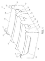
- Tray assembly 10 includes a display housing or tray 12 supporting product packages 14.
- the product packages are preferably packages which support a plurality of comestible products such as gum sticks, slabs, pellets or the like which may be wrapped or unwrapped.
- each individual package 14 may be wrapped with an environmental overwrap (not shown) to environmentally protect the products contained therein.
- the tray 12 includes a planar bottom wall 20 which is opposed to an upper open end 22.
- the tray 12 is generally rectangular in shape having a pair of opposed longitudinal side walls 24 and opposed transverse end walls 26. It may also be appreciated that other shapes and configurations of the tray may be employed where the dimensions of the side walls and end walls may be changed. Moreover, other geometric shapes are within the contemplation of the present invention.
- the end walls 26 define a centrally positioned recessed location 28 which provides front and back access to the packages 14 contained therein and also allows viewing of any advertising or informational indicia contained on the package 14.
- the tray 12 preferably with respect to one or more of the side walls 24, includes an undulated upper extent 30 defining alternating recesses 32 and wall portions 34 therebetween.
- the recesses 32 which may include a rounded bottom 36, extend downwardly from the open upper end 22 a substantial portion of the height of side walls 24.
- the wall portions 34 having a rounded upper ends 38, extend upwardly and define the boundary of the open upper end 22 of tray 12.
- Figure 1 provides one illustrative embodiment, where each side wall 24 includes three recesses 32 and four extending wall portions 34.
- the recesses and extending wall portions are shown to be uniform in Figure 1 , the invention is not limited thereto.
- the undulating portion may define recesses and extending wall portions of different size and configuration along the length of the side wall.
- the amplitude and frequency of the undulations need not be uniform along the length of the side wall.
- the undulating portions of both side walls in Figure 1 are a mirror image of each other, this need not be the case.
- the undulating portions on each side wall may differ.
- the tray 12 is held together in a rectangular configuration by adhesively attaching flange portions 27 adjacent front and back walls 26 to the end wall portions 34 of side walls 24. Other securement techniques may also be employed.
- each recess 32 of tray 12 provides manual access to the lateral portions 14a of packages 14.
- the number of recesses 32 on at least one side wall 24 match the number of stacks of packages 14 where the recesses are positioned generally centrally located with respect to each stack of packages 14.
- Such an arrangement allows a user to grasp one package with the thumb and forefinger placed within opposed recess 34 to easily grasp the stacked package.
- each recess 32 has a width at a location next adjacent to a package contained therein which is less than the width of the package.
- the width of the package is defined to be the extent extending along the undulating side wall of tray 12.
- the width of the recesses is further defined to be a width between the upstanding portions at a depth of the adjacent package to be removed. In some embodiments, the depth of each recess 32 extends below the upper extent of the lower most stacked package. Such an arrangement also allows manual access to the lower most package while assuring that the packages do not fall out through the recesses.
- the tray 12 is typically formed to closely conform to the stack packages contained therein, which in absence of the features of the present recesses 32 could make it difficult for the user to manually grasp one package from the tray.
- the recesses 32 formed by the undulating side walls 24 allow the user to grasp the package from the exterior thereof.
- the undulating pattern of side walls 24 not only provides for ease of manual access to the packages contained therein, but also provides manufacturing expediency in the formation of the tray 12.
- Tray 12 is formed from a planar member 40 typically formed of corrugated paper or cardboard, which may be laminated or unlaminated, or a variety of other materials well known in the art.
- the planar member 40 may be cut into a plurality of flat blanks 42 to form a plurality of trays 12. Each blank 42 is then used to form an individual tray 12. While four blanks 42 are shown cut from the planar member 40, it may be appreciated that any number of blanks 42 may be cut from an appropriately sized planar member 40. Furthermore, the blanks 42 may be cut continuously in succession.
- Each blank 42 has the general shape shown in Figure 2 where the undulating side walls 24 extend outwardly in opposite directions. As previously mentioned, the actual shape and size of each undulation on the side walls 24 may be varied, but the blanks 42 are cut such that the wall portions 34 of each side wall are formed from the recesses 32 of a side wall of an adjacent blank 42. Thus, the wall portions 34 and the recesses 32 are interlocked.
- the shape of the undulations in the side walls 24 may include, but are not limited to sine waves, square waves, saw waves, and triangular waves.
- the size of the undulations may be uniform or irregular in size, provided that the wall portions 34 and the recesses 32 interlock. This significantly reduces waste material, as the material cut from the side wall 24 to form the recesses 32 is not waste material but is material forming the wall portion 34 of the adjacent blank 42.
- the term “undulation” or “undulating” is understood to mean any configuration formed by extensions and recesses on the wall which has peaks and troughs of any configuration, uniform or non-uniform. Such configurations may include, but not be limited to waves, castillations, zig-zags, crests and valleys. The peaks and troughs may be of various configurations such as round, squares or plateau shaped. A combination of such shapes may be included along a single wall or more walls.
- side-by-side adjacent blanks 42 are offset slightly so that the longitudinal end wall portion 34 of one blank 42 may be cut from the recesses 32 of the adjacent blank 42. Similar techniques are used to arrange the blank 42 with respect to the end walls 26 and the flange portions 27.
- each blank 42 may be folded along fold lines 50 to form the tray 12 shown in Figure 1 . Thereafter, each individual tray 12 may be wrapped with an environmental overwrap (not shown) to additionally protect the contents of package 14.
- FIGs 3-5 provide a further preferred embodiment of the tray of the present invention.
- the tray 112 includes opposing undulating first and second side walls 123, 125. With reference to Figure 3 , the formation of the tray 112 may be described as a variation of the tray 12 described in Figures 112 .
- the tray 112 is formed from a planar member 140 typically formed of corrugated paper or cardboard, which may be laminated or unlaminated, or a variety of other materials well known in the art.
- the planar member 140 may be cut into a plurality of flat blanks 142 to form a plurality of trays 112.
- Each blank 142 is used to form an individual tray 112. While two blanks 142 are shown cut from a planar member 140, it may be appreciated that any number of blanks 142 may be cut from an appropriately sized planar member. Furthermore, the blanks 142 may be cut continuously in succession.
- Each blank 142 has the general shape shown in Figure 3 where the first and the second side walls 123, 125 extend outwardly in opposite directions.
- the actual shape and size of each undulation on the side walls 24 may be varied, but the blanks 142 are cut such that the extending wall portions 134 of each side wall are formed from the recesses 132 of a side wall of an adjacent blank 142.
- the extending wall portions 134 and the recesses 132 are interlocked.
- the shape of the undulations in the side walls 123, 125 may include, but are not limited to round or sine waves, square waves, saw waves, and triangular waves.
- the undulations may be uniform or irregular in size, so long as the wall portions 134 and the recesses 132 interlock. This significantly reduces waste material, as the material cut from the first side wall 123 may be used to form the recesses 132 of the second wall 125. Therefore, the material cut to form the extending wall portion 134 of the first side wall 123 is not waste material, but material forming the recesses 132 of the adjacent blank 142 and vice versa.
- side-by-side adjacent blanks 142 may be configured to be longitudinally aligned so that the longitudinal end wall portion 134 of one blank 142 may be cut from the recess 132 of the adjacent blank 142. Similar techniques are used to arrange the blank 142 with respect to the end walls 126 and the flange portions 127.
- the side walls 24 of the tray of Figures 1 -2 are configured so that there is the same arrangement and number of recesses 32 (three) and extending wall portions 34 (four).
- the side walls 123, 125 are configured so that there is a different arrangement and number of recesses 132 and extending wall portions 134.
- one side wall 123 includes three recesses 132 (C, D, E) and two extending wall portions 134 (A, B), while the other side wall 125 includes two recesses 132 (A, B) and three extending wall portions 134 (C, D, E).
- the recesses of one of the side walls are aligned longitudinally with the extending portions of the other side wall and visa versa. The benefit of such an arrangement may be more fully described herein below.
- each blank 142 has two opposing end walls 126.
- Two separate blanks 142 may be folded separately then placed on top of one another to create the cover tray 112 and the bottom tray 112, as shown in Figures 4-5 .
- the arrangement of Figure 3 furthers the reduction of scrap material generated by the blank 142 formation, as compared to the blank 42 of Figure 2 , as a result of the alignment of the blanks 142. Therefore, the blanks 142 of Figure 3 may further reduce the cost of manufacturing the tray 112.
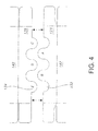
- Figure 4 shows a partial view of two blanks 142 after being cut and separated.
- Figure 4 shows the tray 112 with the first side wall 123 with two extending wall portions 134 (A, B) and three recess portions 132 (C, D, E) and the second side wall 125, on the opposite side of the tray, with three extending wall portions 134 (C, D, E) and two recess portions 132 (A, B).
- Figure 4 further illustrates how the embodiment may allow the adjacent blank 142 configuration to be longitudinally aligned instead of being longitudinally offset as illustrated in Figure 2 . As noted, this arrangement further reduces the scrap material generated by the blank 142 formation.
- the interlocked arrangement of the side walls 123, 125 also provide a further beneficial feature, shown in Figure 5 .
- Two identically folded trays 112 may serve as the base or bottom tray 112 and an interlocked top cover or top tray 112'.
- the blanks 142 are cut from the planar member 140 in a manner shown in Figure 3 , the cut blanks 142 may be folded along fold lines 150 to form the trays 112.
- One blank 142 may serve as a bottom tray 112, while the other blank 142' may be inverted and serve as a cover tray 112'.
- the trays 112 and 112' may be arranged such that the side wall, 125' of the cover tray 112' is aligned with side wall 123 of bottom tray 112.
- the opposite side walls are similarly disposed. This arrangement allows the undulated side walls to be interlocked or nested within the opposing undulated first and second side walls 123', 125, 123,125'.
- the design of the present embodiment of the invention allows for the manufacture of one blank 142 to be used as both a bottom tray 112 and a cover tray 112'.
- the present invention allows for the product to be displayed, packaged, and shipped using the one tray 112 provided in Figures 3-5 herein.
- Figure 6 provides an example of a blank 242 similar to the blank 142 of Figure 3 , except each blank 242 forms two trays 112, 112', with each tray 112, 112' having one separate end wall 126 and a common end wall 144.
- the blanks 242 are configured to allow one-half of the blank 242 to be folded to create a cover tray 112' and the other half of the blank 242 to be folded to create a bottom tray 112.
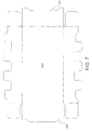
- Figure 7 shoves a blank 342 with square undulations.
- Figure 8 shows a blank 442 with plateaus on the edge of the undulations.
- Figure 9 shows a blank 547 with a zig-zag pattern of undulations along the side walls.
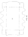
- Figure 10 shows a blank 647 having side walls with a non-uniform pattern of undulations therealong.
- Figure 11 shows a blank 747 having only one side wall including undulations therealong. The opposed side wall has no undulations.
- the undulations of the side wall of Figure 11 may be of any configuration, both uniform and non-uniform.
Landscapes
- Engineering & Computer Science (AREA)
- Mechanical Engineering (AREA)
- Cartons (AREA)
- Containers Having Bodies Formed In One Piece (AREA)
- Stackable Containers (AREA)
- Basic Packing Technique (AREA)
Abstract
Description
- The present invention restates generality to a display tray for supporting a plurality of stacked consumable product packages. More particularly, the present invention relates to a packaging and display tray formed from a plurality of interlocked flat blanks.
- Gum and other consumable products are typically packaged and sold in product packages containing a plurality of such products arranged in an array. The individual product packages may be overwrapped with a wrap which provides environmental protection to the product contained therein. A plurality of such packages may then be arranged in a stacked fashion in a tray or other housing for shipping.
- In addition to providing a convenient housing for shipping a plurality of such packages, the package itself may also serve as a display and dispensing tray at the point of sale. Trays of this type typically include a bottom wall and an upstanding perimetrical wall formed in a rectangular configuration. The upper end of the tray is typically opened so that the user may reach into the tray and pick out individual product packages. However, as may be appreciated, it is often difficult to reach deeply into the product package due to the upstanding side walls. The consumer's fingers must fit into the tray which is typically sized to closely accommodate the packages contained therein.
- Moreover, such dispensing trays are folded from flat blanks cut from a continuous planar stock. Quite often, due to the particular shape of the tray, there is often waste material between adjacent trays. This increases the cost of manufacture of such trays.
-
- It is, therefore, desirable to provide a product display and dispensing tray for accommodating packages of consumable products which allows the consumer to more easily grasp the product contained therein and which can be formed with less waste during the formation process.
- The present invention provides a combination of a tray and of a plurality of comestible product packages according to
claim 1. -
-
Figure 1 is a perspective showing of a display tray of the present invention supporting a plurality of consumable product packages therein. -
Figure 2 shows an arrangement of a planar member including blanks used to form the tray ofFigure 1 . -
Figure 3 shows a further embodiment of an arrangement of a planar member including blanks used to form a tray similar toFigure 1 . -
Figure 4 shows a portion of the blanks ofFigure 3 , after the blanks are cut and separated. -
Figure 5 is a side view showing two trays formed from the blanks ofFigure 3 stacked to form a bottom tray and a top cover. -
Figure 6 shows an example of a blank similar to the blank ofFigure 3 , except each blank forms a bottom and a cover tray with a common end wall attaching the trays. -
Figure 7 shows a further embodiment of the blanks with square shaped undulations on the side walls. -
Figure 8 shows a further embodiment of the blanks with plateau shaped undulations on the side walls. -
Figures 9 and10 show further configurations of the undulations of the side waits of the tray of the present invention. -
Figure 11 shows a further configuration of the tray of the present invention with undulations along one side wall. - The present invention provides a packaging and display tray for accommodating and dispensing a plurality of product packages. In a preferred embodiment, the product packages contained in the tray are gum packages. However, the present invention may be employed with any packaged comestible item. While the present invention is described for accommodating a plurality of product packages, it is understood that the tray may be used to accommodate a single product package.
- Referring to
Figure 1 , adisplay tray assembly 10 of the present invention is shown.Tray assembly 10 includes a display housing or tray 12 supportingproduct packages 14. The product packages are preferably packages which support a plurality of comestible products such as gum sticks, slabs, pellets or the like which may be wrapped or unwrapped. Moreover, eachindividual package 14 may be wrapped with an environmental overwrap (not shown) to environmentally protect the products contained therein. - In the embodiment shown in
Figure 1 , where a plurality of stacked packages are shown, ninepackages 14 are arranged in a single row stacked three deep. However, as may be appreciated, any number of packages arranged in various orientations may be employed with the present invention by changing the size and shape of thetray 12. Thetray 12 includes aplanar bottom wall 20 which is opposed to an upperopen end 22. Thetray 12 is generally rectangular in shape having a pair of opposedlongitudinal side walls 24 and opposedtransverse end walls 26. It may also be appreciated that other shapes and configurations of the tray may be employed where the dimensions of the side walls and end walls may be changed. Moreover, other geometric shapes are within the contemplation of the present invention. - The
end walls 26 define a centrally positionedrecessed location 28 which provides front and back access to thepackages 14 contained therein and also allows viewing of any advertising or informational indicia contained on thepackage 14. - The
tray 12, preferably with respect to one or more of theside walls 24, includes an undulatedupper extent 30 definingalternating recesses 32 andwall portions 34 therebetween. Therecesses 32, which may include arounded bottom 36, extend downwardly from the open upper end 22 a substantial portion of the height ofside walls 24. Thewall portions 34, having a roundedupper ends 38, extend upwardly and define the boundary of the openupper end 22 oftray 12. -
Figure 1 provides one illustrative embodiment, where eachside wall 24 includes threerecesses 32 and four extendingwall portions 34. However, other numbers and arrangements are also within the contemplation of the present invention. Moreover, while the recesses and extending wall portions are shown to be uniform inFigure 1 , the invention is not limited thereto. The undulating portion may define recesses and extending wall portions of different size and configuration along the length of the side wall. For example, the amplitude and frequency of the undulations need not be uniform along the length of the side wall. In addition, while the undulating portions of both side walls inFigure 1 are a mirror image of each other, this need not be the case. The undulating portions on each side wall may differ. - The
tray 12 is held together in a rectangular configuration by adhesively attachingflange portions 27 adjacent front andback walls 26 to theend wall portions 34 ofside walls 24. Other securement techniques may also be employed. - As may be appreciated, when configured as shown in
Figure 1 , therecesses 32 oftray 12 provide manual access to the lateral portions 14a ofpackages 14. In that regard, in one embodiment, it is preferable to have the number ofrecesses 32 on at least oneside wall 24 match the number of stacks ofpackages 14 where the recesses are positioned generally centrally located with respect to each stack ofpackages 14. Such an arrangement, for example, allows a user to grasp one package with the thumb and forefinger placed withinopposed recess 34 to easily grasp the stacked package. In a preferred embodiment, such as shown inFigure 1 , eachrecess 32 has a width at a location next adjacent to a package contained therein which is less than the width of the package. This arrangement maintains the package in the tray yet allows manual grasping access thereto. The width of the package is defined to be the extent extending along the undulating side wall oftray 12. The width of the recesses is further defined to be a width between the upstanding portions at a depth of the adjacent package to be removed. In some embodiments, the depth of eachrecess 32 extends below the upper extent of the lower most stacked package. Such an arrangement also allows manual access to the lower most package while assuring that the packages do not fall out through the recesses. - In order to more efficiently display the packages, the
tray 12 is typically formed to closely conform to the stack packages contained therein, which in absence of the features of the present recesses 32 could make it difficult for the user to manually grasp one package from the tray. Therecesses 32 formed by the undulatingside walls 24 allow the user to grasp the package from the exterior thereof. As will be discussed hereinbelow, the undulating pattern ofside walls 24 not only provides for ease of manual access to the packages contained therein, but also provides manufacturing expediency in the formation of thetray 12. - Referring now to
Figure 2 , the formation oftray 12 may be described.Tray 12 is formed from aplanar member 40 typically formed of corrugated paper or cardboard, which may be laminated or unlaminated, or a variety of other materials well known in the art. Theplanar member 40 may be cut into a plurality offlat blanks 42 to form a plurality oftrays 12. Each blank 42 is then used to form anindividual tray 12. While fourblanks 42 are shown cut from theplanar member 40, it may be appreciated that any number ofblanks 42 may be cut from an appropriately sizedplanar member 40. Furthermore, theblanks 42 may be cut continuously in succession. - Each blank 42 has the general shape shown in
Figure 2 where the undulatingside walls 24 extend outwardly in opposite directions. As previously mentioned, the actual shape and size of each undulation on theside walls 24 may be varied, but theblanks 42 are cut such that thewall portions 34 of each side wall are formed from therecesses 32 of a side wall of an adjacent blank 42. Thus, thewall portions 34 and therecesses 32 are interlocked. - For example, the shape of the undulations in the
side walls 24 may include, but are not limited to sine waves, square waves, saw waves, and triangular waves. Furthermore, as noted, the size of the undulations may be uniform or irregular in size, provided that thewall portions 34 and therecesses 32 interlock. This significantly reduces waste material, as the material cut from theside wall 24 to form therecesses 32 is not waste material but is material forming thewall portion 34 of the adjacent blank 42. - As used herein throughout, the term "undulation" or "undulating" is understood to mean any configuration formed by extensions and recesses on the wall which has peaks and troughs of any configuration, uniform or non-uniform. Such configurations may include, but not be limited to waves, castillations, zig-zags, crests and valleys. The peaks and troughs may be of various configurations such as round, squares or plateau shaped. A combination of such shapes may be included along a single wall or more walls.
- In that regard, side-by-side
adjacent blanks 42 are offset slightly so that the longitudinalend wall portion 34 of one blank 42 may be cut from therecesses 32 of the adjacent blank 42. Similar techniques are used to arrange the blank 42 with respect to theend walls 26 and theflange portions 27. - as shown in
Figure 2 , theend walls 26 of the longitudinallyadjacent blanks 42 are interlocked or nested as are theflange portions 27 with awall portion 34 of the next adjacent blank 42. this arrangement significantly reduces scrap material generated by the blank 42 formation and, therefore, results in a cost reduction in the manufacture of thetray 12. - Once the
blanks 42 are cut from theplanar member 40 in a manner shown inFigure 2 , each blank 42 may be folded alongfold lines 50 to form thetray 12 shown inFigure 1 . Thereafter, eachindividual tray 12 may be wrapped with an environmental overwrap (not shown) to additionally protect the contents ofpackage 14. -
Figures 3-5 provide a further preferred embodiment of the tray of the present invention. Thetray 112 includes opposing undulating first andsecond side walls Figure 3 , the formation of thetray 112 may be described as a variation of thetray 12 described inFigures 112 . Thetray 112 is formed from aplanar member 140 typically formed of corrugated paper or cardboard, which may be laminated or unlaminated, or a variety of other materials well known in the art. Theplanar member 140 may be cut into a plurality offlat blanks 142 to form a plurality oftrays 112. - Each blank 142 is used to form an
individual tray 112. While twoblanks 142 are shown cut from aplanar member 140, it may be appreciated that any number ofblanks 142 may be cut from an appropriately sized planar member. Furthermore, theblanks 142 may be cut continuously in succession. - Each blank 142 has the general shape shown in
Figure 3 where the first and thesecond side walls side walls 24 may be varied, but theblanks 142 are cut such that the extendingwall portions 134 of each side wall are formed from therecesses 132 of a side wall of an adjacent blank 142. Thus, the extendingwall portions 134 and therecesses 132 are interlocked. - For example, as in the previous embodiment, the shape of the undulations in the
side walls wall portions 134 and therecesses 132 interlock. This significantly reduces waste material, as the material cut from thefirst side wall 123 may be used to form therecesses 132 of thesecond wall 125. Therefore, the material cut to form the extendingwall portion 134 of thefirst side wall 123 is not waste material, but material forming therecesses 132 of the adjacent blank 142 and vice versa. - In that regard, side-by-side
adjacent blanks 142 may be configured to be longitudinally aligned so that the longitudinalend wall portion 134 of one blank 142 may be cut from therecess 132 of the adjacent blank 142. Similar techniques are used to arrange the blank 142 with respect to theend walls 126 and theflange portions 127. - As discussed above, the
side walls 24 of the tray ofFigures 1 -2 are configured so that there is the same arrangement and number of recesses 32 (three) and extending wall portions 34 (four). In the present embodiment, shown inFigure 3 , theside walls recesses 132 and extendingwall portions 134. In the embodiment shown inFigure 3 , oneside wall 123 includes three recesses 132 (C, D, E) and two extending wall portions 134 (A, B), while theother side wall 125 includes two recesses 132 (A, B) and three extending wall portions 134 (C, D, E). This, the recesses of one of the side walls are aligned longitudinally with the extending portions of the other side wall and visa versa. The benefit of such an arrangement may be more fully described herein below. - As shown in
Figure 3 , theend walls 126 of theadjacent blanks 142 are longitudinally aligned. Theflange portion 127 of each blank 142 is also longitudinally aligned with theflange portion 127 of the adjacent blank 142. This arrangement shows each blank 142 having two opposingend walls 126. Twoseparate blanks 142 may be folded separately then placed on top of one another to create thecover tray 112 and thebottom tray 112, as shown inFigures 4-5 . - The arrangement of
Figure 3 furthers the reduction of scrap material generated by the blank 142 formation, as compared to the blank 42 ofFigure 2 , as a result of the alignment of theblanks 142. Therefore, theblanks 142 ofFigure 3 may further reduce the cost of manufacturing thetray 112. -
Figure 4 shows a partial view of twoblanks 142 after being cut and separated.Figure 4 shows thetray 112 with thefirst side wall 123 with two extending wall portions 134 (A, B) and three recess portions 132 (C, D, E) and thesecond side wall 125, on the opposite side of the tray, with three extending wall portions 134 (C, D, E) and two recess portions 132 (A, B).Figure 4 further illustrates how the embodiment may allow the adjacent blank 142 configuration to be longitudinally aligned instead of being longitudinally offset as illustrated inFigure 2 . As noted, this arrangement further reduces the scrap material generated by the blank 142 formation. - The interlocked arrangement of the
side walls Figure 5 . Two identically foldedtrays 112 may serve as the base orbottom tray 112 and an interlocked top cover or top tray 112'. Theblanks 142 are cut from theplanar member 140 in a manner shown inFigure 3 , thecut blanks 142 may be folded alongfold lines 150 to form thetrays 112. One blank 142 may serve as abottom tray 112, while the other blank 142' may be inverted and serve as a cover tray 112'. Thetrays 112 and 112' may be arranged such that the side wall, 125' of the cover tray 112' is aligned withside wall 123 ofbottom tray 112. As may be applied, the opposite side walls (not shown) are similarly disposed. This arrangement allows the undulated side walls to be interlocked or nested within the opposing undulated first andsecond side walls 123', 125, 123,125'. - The design of the present embodiment of the invention allows for the manufacture of one blank 142 to be used as both a
bottom tray 112 and a cover tray 112'. Thus, the present invention allows for the product to be displayed, packaged, and shipped using the onetray 112 provided inFigures 3-5 herein. -
Figure 6 provides an example of a blank 242 similar to the blank 142 ofFigure 3 , except each blank 242 forms twotrays 112, 112', with eachtray 112, 112' having oneseparate end wall 126 and acommon end wall 144. Theblanks 242 are configured to allow one-half of the blank 242 to be folded to create a cover tray 112' and the other half of the blank 242 to be folded to create abottom tray 112. - Other configurations of the blanks further contemplated include, but are not limited to varying the size and shape of the undulating areas, such as square undulations, triangle undulation, and plateaus on the edge of undulations. Moreover, the size of the undulations may be varied or irregular so that the undulations on the end of the sides are smaller than in the center undulations and vice versa.
Figures 7-8 provide examples of other blank configurations. - Specifically,
Figure 7 shoves a blank 342 with square undulations.Figure 8 shows a blank 442 with plateaus on the edge of the undulations.Figure 9 shows a blank 547 with a zig-zag pattern of undulations along the side walls.Figure 10 shows a blank 647 having side walls with a non-uniform pattern of undulations therealong.Figure 11 shows a blank 747 having only one side wall including undulations therealong. The opposed side wall has no undulations. The undulations of the side wall ofFigure 11 may be of any configuration, both uniform and non-uniform. -
-
Item 1. A tray for accommodating and dispensing a stacked plurality of comestible product packages conprising:- a housing having a bottom wall, opposed front and back walls and opposed side walls extending upwardly from said bottom wall and defining an open upper end;
- Item 2. A tray of
item 1 wherein said side walls include said undulating upper extent and said recesses. - Item 3. A tray of item 2 wherein said side walls include a first side wall and a second side wall.
- Item 4. A tray of item 3 wherein said first side wall contains a first number of recesses and said second side wall contains a second number of recesses.
- Item 5. A tray of item 4 wherein said first number of recesses is the same as said second number of recesses.
- Item 6. A tray of item 4 wherein said first number of recesses is different than said second number of recesses.
- Item 7. A tray of item 6 wherein said recesses of said first side wall directly oppose said upwardly extending wall portions of said second side wall.
- Item 8. A tray of items 1 -7 wherein said recesses have a round bottom.
- Item 9. A tray of items 1-7 wherein said recesses have a square bottom.
-
Item 10. A tray of items 1-7 wherein said recesses have a plateau, shaped bottom. - Item 11. A tray of items 1-7 wherein said undulating upper extent defines an upwardly extending wall portion between each said recess.
- Item 2. A tray of item 11 wherein said upwardly extending wall portions are rounded.
- Item 13. A tray of item 11 wherein said upwardly extending wall portions are square shaped.
-
Item 14. A tray of item 11 wherein said upwardly extending wall portions are plateau shaped. - Item 15. A tray of item 11 wherein said upwardly extending wall portions are zig-zag shaped.
- Item 16. A method of forming a tray for accommodating and dispensing a stacked plurality of consumable products packages comprising the steps of:
- providing a planar member;
- cutting a plurality of adjacently arranged flat blanks from said planar member, said blanks each having opposed longitudinal edges each having an undulating configuration defining alternating extensions and recesses, said extensions of one said blank being formed in the recesses of the adjacent said blank; and
- folding each said blank into a tray-shaped housing having a bottom wall and an opposed open end, wherein said opposed longitudinal edges define side walls of said housing.
- Item 17 . A method of item 16 wherein said cutting step further includes continuously cutting a plurality of said blanks in succession.
- Item 18. A method of item 16 wherein said cutting step further includes cutting a first side wall such that said first side wall contains a first number of said recesses.
- Item 19. A method of item 18 therein said cutting step further includes cutting a second side wall such that said second side wall contains a second number of said recesses, wherein said first number of said recesses is the same as said second number of said recesses.
-
item 20. A method of item 18 wherein said cutting step further includes cutting a second side wall such that said second side wall contains a second number of said recesses, wherein said second number of said recesses is different than said first number of said recesses. - Item 21. A method of items 16-20 wherein said folding step includes folding said housing to form opposed end walls.
-
Item 22. A method of items 16-20 further comprising placing a tray on top of another tray to create a cover, wherein each said first side wall and each said second side wall are configured such that each said recess of said first side wall fits into each said extension of said second side wall. - Item 23. A method of
item 22, wherein two adjacent blanks are configured to be foldably connected by a common wall, said common wall replaces one of said end walls on each of said two adjacent blanks. -
Item 24. A method of item 23, wherein said cutting step further including cutting said two adjacent blanks, said common wall holding said two adjacent blanks together. - Item 25. A method of
item 24 wherein said folding steps further include folding said two adjacent blanks to form two attached trays with a cover tray and a bottom tray connected by said common end wall. -
Item 26. A method of items 16-20 wherein said flat blanks are arranged such that said undulations on the opposing side walls are nested and longitudinally aligned. -
Item 27. A method of items 16-20 wherein said flat blanks are arranged such that said undulations on the opposing side walls are nested and longitudinally offset. -
Item 28. A tray assembly comprising:- a first tray configured to be a bottom tray; and
- a second tray configured to be a cover tray, said first said second trays being identically configured;
- said first tray and said second tray each including a bottom wall, opposed front and back walls, and opposed side walls extending upwardly from said bottom wall and defining an upper open end, said opposed side walls further including an undulating configuration defining alternating extensions and recesses on said opposed side walls,
- Item 29. A tray of
item 28 wherein said side walls include a first side wall and a second side wall. -
Item 30. A tray of item 29 wherein said first side wall contains a first number of recesses and said second side wall contains a second number of recessees. - Item 31. A tray of
item 30 wherein said first number of recesses is the same as said second number of recesses. -
Item 32. A tray ofitem 30 wherein said first number of recesses is different than said second number of recesses. - Item 33. A tray of
item 32 wherein said recesses of said first side wall directly oppose said upwardly extending wall portions of said second side wall. -
Item 34. In combination, a tray and at least one comestible product package, said combination comprising:- a tray housing for accommodating said product package, said tray housing having a bottom wall, a pair of opposed longitudinal side walls and opposed transverse end walls defining a housing perimeter upstanding from said bottom wall;
- at least one of said side walls including an undulating pattern of recesses and wall portions extending the length of the side wall, said recesses permitting manual access to said package through said side walls.
- Item 35. The combination of
item 34 wherein said product package has an upper extent and said recesses extend below said upper extent of said product package supported in said tray housing. -
Item 36. The combination of items 34-35 wherein said product package is supported adjacent one said recess and wherein said recess has a width adjacent said product package which is less than the width of said product package supported in said tray housing. - Item 37. The combination of items 34-36 which said undulating pattern is uniform along said side walls.
-
Item 38. The combination of items 34-36 wherein said undulating portion of each of said side wall is such that the recesses of one side wall are longitudinally aligned with the wall portions of the other side wall. - Item 39. The combination of items 34-36 wherein said undulating pattern of each side wall is such that the recesses of one side wall are longitudinally aligned with the recesses of the other side wall.
-
Item 40. The combination ofitem 38 further including a pair of said tray housings wherein one said tray housing of said pair is nestable with the other said tray housing of said pair and wherein the wall portions of said one tray housing fit into the recesses of the other tray housing. - Item 41. The combination of items 34-36 wherein said tray housing is formed from a flat blank.
-
Item 42. The combination of item 41 wherein said pair of said tray housings are formed from adjacent nested flat blanks wherein the wall portions of one of said tray housing is formed from the recesses of said other tray housing. - Item 43. A flat sheet of material for forming a plurality of packaging trays comprising:
- a first tray blank formed in said sheet, said first blank having a generally rectangular configuration including opposed longitudinal side walls and opposed transverse end walls, said side walls having an undulating pattern therealong defining alternating recesses and extending portions;
- a second tray blank formed in said sheet, said second blank having a generally rectangular configuration including opposed longitudinal side walls and opposed transverse end walls, said side walls having an undulating pattern therealong defining alternating recesses and extending portions;
- Item 44. A flat sheet of item 43 wherein each of said side walls of each of said first and second tray blanks have the same number of recesses and extending portions therealong and wherein said adjacent first and second tray blanks are longitudinally staggered.
- Item 45. A flat sheet of item 43 wherein each of said side walls of each of said first and second tray blanks have a different number of recesses and extending portions therealong and wherein said adjacent first and second tray blanks are longitudinally aligned.
- Item 46. A flat sheet of item 45 wherein one of said first and second tray blanks is constructed to define a tray housing for accommodating at least one comestible product package therein.
- Item 47. A flat sheet of claim 46 wherein the other of said first and second tray blanks is constructed to define a tray cover for overlying nesting engagement with said one tray housing.
- Various changes to the foregoing described and shown structures would now be evident to those skilled in the art. Accordingly, the particularly disclosed scope of the invention is set forth in the following claims.
Claims (14)
- In combination, a tray (12) and a plurality of comestible product packages (14) said combination comprising:a tray housing accommodating said plurality of comestible product packages, said tray having a bottom wall (20), opposed front and back walls (26) and opposed side walls (24) extending upwardly from said bottom wall and defining an open upper end (22),where at least one of said opposed front, back or said side walls include an undulating upper extent (30) defined by spaced apart upwardly opening recesses(32);characterised in that the product packages (14) are arranged in stacks in the tray (12) and wherein at least one stack of product packages is aligned adjacent a recess (32), said recess having an open portion extending below an upper extent of the uppermost product package in the stack for permitting manual grasping of individual packages in the stack through said at least one of said opposed front and back walls and said side walls and wherein the recess (32) has a width which is less than the width of said product packages (19) in the stack.
- A combination as claimed in claim 1 wherein said side walls include said undulating upper extent (30) and said recesses (32).
- A combination as claimed in claim 2 wherein the number of recesses (32) on a first side wall is the same as the number of recesses on a second side wall.
- A combination as claimed in claim 2 wherein the number of recesses (32) on a first side wall is different than the number of recesses on a second side wall.
- A combination as claimed in claim 4 wherein said recesses (32) of said first side wall directly oppose said upwardly extending wall portions of said second side wall.
- A combination as claimed in any one of the preceding claims, wherein the tray is a first tray (112), opposed side walls of the first tray (112) including the undulating is a first tray (112), the opposed side walls of the first tray (112) including the undulating upper extent/which defines alternating extensions and recesses, the combination also comprising:a second tray (112') configured to be a cover tray;said second tray (112') including a bottom wall, opposed front and back walls, and opposed side walls extending upwardly from said bottom wall and defining an upper open end, said opposed side walls further including an undulating configuration defining alternating extensions and recesses on said opposed side walls,wherein said second tray (112') is configured to fit on top of said first tray (112) with said extensions of said first tray aligned and nested with said recesses of said second tray and said recesses of said first tray aligned and nested with said extensions of said second tray.
- A combination as claimed in any one of the preceding claims wherein said undulating pattern is uniform along said at least one of said opposed front, back, or said side walls.
- A combination as claimed in claim 3 wherein said undulating pattern of each side wall is such that the recesses of one side wall are longitudinally aligned with the recesses of the other side wall.
- A combination as claimed in any one of the preceding claims wherein said tray is formed from a flat blank.
- A combination as claimed in claim 6 wherein said first and second trays are formed from adjacent nested flat blanks wherein the wall portions of one of said tray is formed from the recesses of said other tray.
- A combination as claimed in claim 10, wherein each of said wall portions of each of said first and second tray blanks have the same number of recesses and extending portions therealong and wherein said adjacent first and second tray blanks are longitudinally staggered.
- A combination as claimed in claim 10, wherein each of said side walls of each of said first and second tray blanks have a different number of recesses and extending portions therealong and wherein said adjacent first and second tray blanks are longitudinally aligned.
- A combination as claimed in any one of the preceding claims, in which said recess has an open portion extending below an upper extent of the lowermost product package in the stack.
- A combination as claimed in any one of the preceding claims, in which at least one side wall includes said undulating upper extent defined by spaced apart upwardly opening recesses and wherein the number of recess in said at least one side wall match the number of stacks of packages positioned adjacent said side wall and where the recesses are positioned generally centrally located of their respective stacks.
Priority Applications (1)
| Application Number | Priority Date | Filing Date | Title |
|---|---|---|---|
| PL09747430T PL2282948T3 (en) | 2008-05-14 | 2009-05-13 | Packaging and display tray formed from interlocked blanks |
Applications Claiming Priority (3)
| Application Number | Priority Date | Filing Date | Title |
|---|---|---|---|
| US5307008P | 2008-05-14 | 2008-05-14 | |
| US11680508P | 2008-11-21 | 2008-11-21 | |
| PCT/US2009/043729 WO2009140346A1 (en) | 2008-05-14 | 2009-05-13 | Packaging and display tray formed from interlocked blanks |
Publications (2)
| Publication Number | Publication Date |
|---|---|
| EP2282948A1 EP2282948A1 (en) | 2011-02-16 |
| EP2282948B1 true EP2282948B1 (en) | 2012-01-04 |
Family
ID=40908538
Family Applications (1)
| Application Number | Title | Priority Date | Filing Date |
|---|---|---|---|
| EP09747430A Not-in-force EP2282948B1 (en) | 2008-05-14 | 2009-05-13 | Packaging and display tray formed from interlocked blanks |
Country Status (12)
| Country | Link |
|---|---|
| US (1) | US20090283581A1 (en) |
| EP (1) | EP2282948B1 (en) |
| JP (2) | JP2011520715A (en) |
| CN (1) | CN102026882B (en) |
| AT (1) | ATE539971T1 (en) |
| AU (1) | AU2009246428B2 (en) |
| CA (1) | CA2723755C (en) |
| ES (1) | ES2378445T3 (en) |
| MX (1) | MX2010012493A (en) |
| PL (1) | PL2282948T3 (en) |
| WO (1) | WO2009140346A1 (en) |
| ZA (1) | ZA200903291B (en) |
Cited By (1)
| Publication number | Priority date | Publication date | Assignee | Title |
|---|---|---|---|---|
| DE102023131101A1 (en) | 2023-11-09 | 2025-05-15 | Amecke Markenvertrieb GmbH & Co. KG | Outer packaging for beverage cartons |
Families Citing this family (11)
| Publication number | Priority date | Publication date | Assignee | Title |
|---|---|---|---|---|
| US20150375889A1 (en) * | 2010-09-15 | 2015-12-31 | Robert David Brockman | Under Sink Leak Protector Tray and Associated Method |
| GB201205243D0 (en) | 2012-03-26 | 2012-05-09 | Kraft Foods R & D Inc | Packaging and method of opening |
| GB2511560B (en) | 2013-03-07 | 2018-11-14 | Mondelez Uk R&D Ltd | Improved Packaging and Method of Forming Packaging |
| GB2511559B (en) | 2013-03-07 | 2018-11-14 | Mondelez Uk R&D Ltd | Improved Packaging and Method of Forming Packaging |
| DE102013110764A1 (en) * | 2013-09-27 | 2015-04-02 | Van Genechten Packaging N.V. | carton blank |
| EP3095915B1 (en) | 2015-05-20 | 2019-01-16 | Sika Technology AG | Application of a fabric for roadway structure having improved adhesive properties |
| JP7012024B2 (en) * | 2016-04-15 | 2022-01-27 | エコ. ロジック ブランズ インコーポレイテッド | Interconnection means for multi-part containers |
| CN112224594B (en) * | 2020-10-26 | 2022-08-05 | 上海八彦图信息科技有限公司 | Ginseng honoured guest certificate sorting device |
| CN114803046A (en) * | 2021-01-29 | 2022-07-29 | 维实洛克包装系统有限公司 | Carton and blank therefor |
| WO2022250713A1 (en) * | 2021-05-25 | 2022-12-01 | Citadel Casing Ltd | Interlocking case inserts |
| USD1043370S1 (en) | 2021-06-22 | 2024-09-24 | Citadel Casing Ltd | Packaging |
Family Cites Families (21)
| Publication number | Priority date | Publication date | Assignee | Title |
|---|---|---|---|---|
| US2027747A (en) * | 1934-10-30 | 1936-01-14 | Hinde & Dauch Paper Co | Joined structure |
| US2888132A (en) * | 1955-08-12 | 1959-05-26 | Waldorf Paper Prod Co | Divisible carton |
| US3521748A (en) * | 1968-06-27 | 1970-07-28 | Inland Container Corp | Adjustable depth carton |
| GB1392286A (en) * | 1971-04-05 | 1975-04-30 | Unilever Ltd | Blanks for cartons |
| FR2308553A1 (en) * | 1975-04-23 | 1976-11-19 | Sauterot Drac | Mfg. punnets for cooked foods - by cutting sheet to form blanks having wavy edges formed by single cuts between blanks |
| JPS5346943U (en) * | 1976-09-27 | 1978-04-21 | ||
| JPS5758019U (en) * | 1980-09-19 | 1982-04-06 | ||
| US4746010A (en) * | 1986-06-30 | 1988-05-24 | Stephen Fournier | Box convertible to food item tray |
| US5060851A (en) * | 1988-09-26 | 1991-10-29 | Macmillan Bloedel Containers | Interlocking container for carry-out food products |
| FR2676035A1 (en) * | 1991-04-30 | 1992-11-06 | Cartonnerie Moderne Ets Moulin | Cut-out for making a folding packaging box and box thus obtained |
| US5154292A (en) * | 1991-12-02 | 1992-10-13 | Bartucca Frank A | Sports card sleeve box |
| US5913424A (en) * | 1993-07-14 | 1999-06-22 | Tulip Corporation | Storage and display trays |
| US5839650A (en) * | 1997-03-07 | 1998-11-24 | Triangle Container Corporation | Stackable container |
| US6029803A (en) * | 1999-01-14 | 2000-02-29 | Ovadia Corp. | Display and storage box with interlocking, friction fitting halves |
| US6158653A (en) * | 1999-02-10 | 2000-12-12 | Allen Kanter | Container having improved stacking strength |
| USD469255S1 (en) * | 2001-05-08 | 2003-01-28 | Roy Hammett | Beverage tray |
| GB0202869D0 (en) * | 2002-02-07 | 2002-03-27 | Mead Corp | Carton with overlapped base panels and blank therefor |
| US20050121348A1 (en) * | 2003-12-09 | 2005-06-09 | Clare Timothy P. | Package insert and stackable package for articles |
| US7316319B2 (en) * | 2003-12-23 | 2008-01-08 | Thomas West | Lift van system |
| WO2006084923A1 (en) * | 2005-02-08 | 2006-08-17 | Kappa Iberoamericana, S.A. | Improvements to cardboard boxes for perishable goods and similar |
| GB2437514A (en) * | 2006-04-26 | 2007-10-31 | Sca Packaging Ltd | Display tray for supporting sachets |
-
2009
- 2009-05-13 ZA ZA2009/03291A patent/ZA200903291B/en unknown
- 2009-05-13 US US12/465,021 patent/US20090283581A1/en not_active Abandoned
- 2009-05-13 CN CN200980117476.0A patent/CN102026882B/en not_active Expired - Fee Related
- 2009-05-13 PL PL09747430T patent/PL2282948T3/en unknown
- 2009-05-13 MX MX2010012493A patent/MX2010012493A/en active IP Right Grant
- 2009-05-13 AU AU2009246428A patent/AU2009246428B2/en not_active Ceased
- 2009-05-13 AT AT09747430T patent/ATE539971T1/en active
- 2009-05-13 WO PCT/US2009/043729 patent/WO2009140346A1/en not_active Ceased
- 2009-05-13 EP EP09747430A patent/EP2282948B1/en not_active Not-in-force
- 2009-05-13 ES ES09747430T patent/ES2378445T3/en active Active
- 2009-05-13 CA CA2723755A patent/CA2723755C/en not_active Expired - Fee Related
- 2009-05-13 JP JP2011509635A patent/JP2011520715A/en active Pending
-
2014
- 2014-02-06 JP JP2014021059A patent/JP2014101150A/en active Pending
Cited By (2)
| Publication number | Priority date | Publication date | Assignee | Title |
|---|---|---|---|---|
| DE102023131101A1 (en) | 2023-11-09 | 2025-05-15 | Amecke Markenvertrieb GmbH & Co. KG | Outer packaging for beverage cartons |
| DE102023131101B4 (en) | 2023-11-09 | 2026-01-15 | Amecke Markenvertrieb GmbH & Co. KG | Packaging consisting of beverage cartons and outer packaging, as well as outer packaging for beverage cartons |
Also Published As
| Publication number | Publication date |
|---|---|
| CA2723755A1 (en) | 2009-11-19 |
| US20090283581A1 (en) | 2009-11-19 |
| CA2723755C (en) | 2013-12-31 |
| MX2010012493A (en) | 2010-12-17 |
| ES2378445T3 (en) | 2012-04-12 |
| AU2009246428A1 (en) | 2009-11-19 |
| ATE539971T1 (en) | 2012-01-15 |
| JP2014101150A (en) | 2014-06-05 |
| WO2009140346A1 (en) | 2009-11-19 |
| EP2282948A1 (en) | 2011-02-16 |
| PL2282948T3 (en) | 2012-10-31 |
| JP2011520715A (en) | 2011-07-21 |
| CN102026882A (en) | 2011-04-20 |
| CN102026882B (en) | 2014-01-15 |
| ZA200903291B (en) | 2009-12-30 |
| AU2009246428B2 (en) | 2012-08-23 |
Similar Documents
| Publication | Publication Date | Title |
|---|---|---|
| CA2723755C (en) | Packaging and display tray formed from interlocked blanks | |
| US4930633A (en) | Multiple pack for a plurality of cylindrical containers | |
| JP7576914B2 (en) | Cartons and blanks therefor | |
| US4895295A (en) | Multiple product wraparound carrier | |
| EP2307283A1 (en) | Protection arrangement | |
| US20180282039A1 (en) | Clip-in carrier package for beverage cans | |
| US7857136B2 (en) | Foldable tray for packaging bakery products | |
| KR200492642Y1 (en) | Package box and goods dispenser | |
| EP1934102B1 (en) | Bundle pack | |
| CA2771557A1 (en) | Container blank and container with denesting feature | |
| AU2012258335B2 (en) | Packaging and display tray formed from interlocked blanks | |
| US4467918A (en) | Lateral packaging for holding together superimposed articles | |
| JPH10194330A (en) | Container holder | |
| JP2023507806A (en) | Blanks for packages, goods carriers and goods carriers | |
| US20220324607A1 (en) | Packaging Articles | |
| EP2943411B1 (en) | Reinforced carton | |
| US9926126B2 (en) | Package configuration for empty sheet-formed containers | |
| JP5417955B2 (en) | Paper tray | |
| JP2005153914A (en) | Joining multipack | |
| JP5597442B2 (en) | Cardboard box | |
| US20250033826A1 (en) | Container With Denesting Features | |
| JPH11222229A (en) | Packaging material made of corrugated fiberboard | |
| WO1994027891A1 (en) | Stackable trays | |
| US20090223978A1 (en) | Display stand with disposable serving containers | |
| JP2011116432A (en) | Pack for bunched-up container |
Legal Events
| Date | Code | Title | Description |
|---|---|---|---|
| PUAI | Public reference made under article 153(3) epc to a published international application that has entered the european phase |
Free format text: ORIGINAL CODE: 0009012 |
|
| 17P | Request for examination filed |
Effective date: 20101028 |
|
| AK | Designated contracting states |
Kind code of ref document: A1 Designated state(s): AT BE BG CH CY CZ DE DK EE ES FI FR GB GR HR HU IE IS IT LI LT LU LV MC MK MT NL NO PL PT RO SE SI SK TR |
|
| AX | Request for extension of the european patent |
Extension state: AL BA RS |
|
| DAX | Request for extension of the european patent (deleted) | ||
| GRAP | Despatch of communication of intention to grant a patent |
Free format text: ORIGINAL CODE: EPIDOSNIGR1 |
|
| GRAS | Grant fee paid |
Free format text: ORIGINAL CODE: EPIDOSNIGR3 |
|
| GRAA | (expected) grant |
Free format text: ORIGINAL CODE: 0009210 |
|
| AK | Designated contracting states |
Kind code of ref document: B1 Designated state(s): AT BE BG CH CY CZ DE DK EE ES FI FR GB GR HR HU IE IS IT LI LT LU LV MC MK MT NL NO PL PT RO SE SI SK TR |
|
| REG | Reference to a national code |
Ref country code: GB Ref legal event code: FG4D |
|
| REG | Reference to a national code |
Ref country code: CH Ref legal event code: EP |
|
| REG | Reference to a national code |
Ref country code: AT Ref legal event code: REF Ref document number: 539971 Country of ref document: AT Kind code of ref document: T Effective date: 20120115 |
|
| RAP2 | Party data changed (patent owner data changed or rights of a patent transferred) |
Owner name: KRAFT FOODS GLOBAL BRANDS LLC |
|
| REG | Reference to a national code |
Ref country code: IE Ref legal event code: FG4D |
|
| REG | Reference to a national code |
Ref country code: DE Ref legal event code: R096 Ref document number: 602009004571 Country of ref document: DE Effective date: 20120301 |
|
| REG | Reference to a national code |
Ref country code: ES Ref legal event code: FG2A Ref document number: 2378445 Country of ref document: ES Kind code of ref document: T3 Effective date: 20120412 |
|
| REG | Reference to a national code |
Ref country code: NL Ref legal event code: VDEP Effective date: 20120104 |
|
| PG25 | Lapsed in a contracting state [announced via postgrant information from national office to epo] |
Ref country code: SI Free format text: LAPSE BECAUSE OF FAILURE TO SUBMIT A TRANSLATION OF THE DESCRIPTION OR TO PAY THE FEE WITHIN THE PRESCRIBED TIME-LIMIT Effective date: 20120104 |
|
| LTIE | Lt: invalidation of european patent or patent extension |
Effective date: 20120104 |
|
| PG25 | Lapsed in a contracting state [announced via postgrant information from national office to epo] |
Ref country code: NO Free format text: LAPSE BECAUSE OF FAILURE TO SUBMIT A TRANSLATION OF THE DESCRIPTION OR TO PAY THE FEE WITHIN THE PRESCRIBED TIME-LIMIT Effective date: 20120404 Ref country code: IS Free format text: LAPSE BECAUSE OF FAILURE TO SUBMIT A TRANSLATION OF THE DESCRIPTION OR TO PAY THE FEE WITHIN THE PRESCRIBED TIME-LIMIT Effective date: 20120504 Ref country code: BE Free format text: LAPSE BECAUSE OF FAILURE TO SUBMIT A TRANSLATION OF THE DESCRIPTION OR TO PAY THE FEE WITHIN THE PRESCRIBED TIME-LIMIT Effective date: 20120104 Ref country code: NL Free format text: LAPSE BECAUSE OF FAILURE TO SUBMIT A TRANSLATION OF THE DESCRIPTION OR TO PAY THE FEE WITHIN THE PRESCRIBED TIME-LIMIT Effective date: 20120104 Ref country code: LT Free format text: LAPSE BECAUSE OF FAILURE TO SUBMIT A TRANSLATION OF THE DESCRIPTION OR TO PAY THE FEE WITHIN THE PRESCRIBED TIME-LIMIT Effective date: 20120104 Ref country code: BG Free format text: LAPSE BECAUSE OF FAILURE TO SUBMIT A TRANSLATION OF THE DESCRIPTION OR TO PAY THE FEE WITHIN THE PRESCRIBED TIME-LIMIT Effective date: 20120404 Ref country code: HR Free format text: LAPSE BECAUSE OF FAILURE TO SUBMIT A TRANSLATION OF THE DESCRIPTION OR TO PAY THE FEE WITHIN THE PRESCRIBED TIME-LIMIT Effective date: 20120104 |
|
| PG25 | Lapsed in a contracting state [announced via postgrant information from national office to epo] |
Ref country code: GR Free format text: LAPSE BECAUSE OF FAILURE TO SUBMIT A TRANSLATION OF THE DESCRIPTION OR TO PAY THE FEE WITHIN THE PRESCRIBED TIME-LIMIT Effective date: 20120405 Ref country code: PT Free format text: LAPSE BECAUSE OF FAILURE TO SUBMIT A TRANSLATION OF THE DESCRIPTION OR TO PAY THE FEE WITHIN THE PRESCRIBED TIME-LIMIT Effective date: 20120504 Ref country code: FI Free format text: LAPSE BECAUSE OF FAILURE TO SUBMIT A TRANSLATION OF THE DESCRIPTION OR TO PAY THE FEE WITHIN THE PRESCRIBED TIME-LIMIT Effective date: 20120104 Ref country code: LV Free format text: LAPSE BECAUSE OF FAILURE TO SUBMIT A TRANSLATION OF THE DESCRIPTION OR TO PAY THE FEE WITHIN THE PRESCRIBED TIME-LIMIT Effective date: 20120104 |
|
| REG | Reference to a national code |
Ref country code: AT Ref legal event code: MK05 Ref document number: 539971 Country of ref document: AT Kind code of ref document: T Effective date: 20120104 |
|
| PG25 | Lapsed in a contracting state [announced via postgrant information from national office to epo] |
Ref country code: CY Free format text: LAPSE BECAUSE OF FAILURE TO SUBMIT A TRANSLATION OF THE DESCRIPTION OR TO PAY THE FEE WITHIN THE PRESCRIBED TIME-LIMIT Effective date: 20120104 |
|
| PG25 | Lapsed in a contracting state [announced via postgrant information from national office to epo] |
Ref country code: RO Free format text: LAPSE BECAUSE OF FAILURE TO SUBMIT A TRANSLATION OF THE DESCRIPTION OR TO PAY THE FEE WITHIN THE PRESCRIBED TIME-LIMIT Effective date: 20120104 Ref country code: EE Free format text: LAPSE BECAUSE OF FAILURE TO SUBMIT A TRANSLATION OF THE DESCRIPTION OR TO PAY THE FEE WITHIN THE PRESCRIBED TIME-LIMIT Effective date: 20120104 Ref country code: DK Free format text: LAPSE BECAUSE OF FAILURE TO SUBMIT A TRANSLATION OF THE DESCRIPTION OR TO PAY THE FEE WITHIN THE PRESCRIBED TIME-LIMIT Effective date: 20120104 Ref country code: CZ Free format text: LAPSE BECAUSE OF FAILURE TO SUBMIT A TRANSLATION OF THE DESCRIPTION OR TO PAY THE FEE WITHIN THE PRESCRIBED TIME-LIMIT Effective date: 20120104 Ref country code: SE Free format text: LAPSE BECAUSE OF FAILURE TO SUBMIT A TRANSLATION OF THE DESCRIPTION OR TO PAY THE FEE WITHIN THE PRESCRIBED TIME-LIMIT Effective date: 20120104 |
|
| REG | Reference to a national code |
Ref country code: PL Ref legal event code: T3 |
|
| PLBE | No opposition filed within time limit |
Free format text: ORIGINAL CODE: 0009261 |
|
| STAA | Information on the status of an ep patent application or granted ep patent |
Free format text: STATUS: NO OPPOSITION FILED WITHIN TIME LIMIT |
|
| PG25 | Lapsed in a contracting state [announced via postgrant information from national office to epo] |
Ref country code: SK Free format text: LAPSE BECAUSE OF FAILURE TO SUBMIT A TRANSLATION OF THE DESCRIPTION OR TO PAY THE FEE WITHIN THE PRESCRIBED TIME-LIMIT Effective date: 20120104 Ref country code: IT Free format text: LAPSE BECAUSE OF FAILURE TO SUBMIT A TRANSLATION OF THE DESCRIPTION OR TO PAY THE FEE WITHIN THE PRESCRIBED TIME-LIMIT Effective date: 20120104 |
|
| 26N | No opposition filed |
Effective date: 20121005 |
|
| PG25 | Lapsed in a contracting state [announced via postgrant information from national office to epo] |
Ref country code: MC Free format text: LAPSE BECAUSE OF NON-PAYMENT OF DUE FEES Effective date: 20120531 |
|
| PG25 | Lapsed in a contracting state [announced via postgrant information from national office to epo] |
Ref country code: AT Free format text: LAPSE BECAUSE OF FAILURE TO SUBMIT A TRANSLATION OF THE DESCRIPTION OR TO PAY THE FEE WITHIN THE PRESCRIBED TIME-LIMIT Effective date: 20120104 |
|
| REG | Reference to a national code |
Ref country code: DE Ref legal event code: R097 Ref document number: 602009004571 Country of ref document: DE Effective date: 20121005 |
|
| REG | Reference to a national code |
Ref country code: IE Ref legal event code: MM4A |
|
| PG25 | Lapsed in a contracting state [announced via postgrant information from national office to epo] |
Ref country code: MK Free format text: LAPSE BECAUSE OF FAILURE TO SUBMIT A TRANSLATION OF THE DESCRIPTION OR TO PAY THE FEE WITHIN THE PRESCRIBED TIME-LIMIT Effective date: 20120104 |
|
| PG25 | Lapsed in a contracting state [announced via postgrant information from national office to epo] |
Ref country code: IE Free format text: LAPSE BECAUSE OF NON-PAYMENT OF DUE FEES Effective date: 20120513 |
|
| PG25 | Lapsed in a contracting state [announced via postgrant information from national office to epo] |
Ref country code: MT Free format text: LAPSE BECAUSE OF FAILURE TO SUBMIT A TRANSLATION OF THE DESCRIPTION OR TO PAY THE FEE WITHIN THE PRESCRIBED TIME-LIMIT Effective date: 20120104 |
|
| REG | Reference to a national code |
Ref country code: DE Ref legal event code: R082 Ref document number: 602009004571 Country of ref document: DE Representative=s name: WEBER & HEIM PATENTANWAELTE, DE |
|
| REG | Reference to a national code |
Ref country code: ES Ref legal event code: PC2A Owner name: INTERCONTINENTAL GREAT BRANDS LLC Effective date: 20131213 |
|
| REG | Reference to a national code |
Ref country code: CH Ref legal event code: PL |
|
| REG | Reference to a national code |
Ref country code: DE Ref legal event code: R081 Ref document number: 602009004571 Country of ref document: DE Owner name: INTERCONTINENTAL GREAT BRANDS LLC, EAST HANOVE, US Free format text: FORMER OWNER: CADBURY ADAMS USA LLC, PARSIPPANY, N.J., US Effective date: 20120716 Ref country code: DE Ref legal event code: R081 Ref document number: 602009004571 Country of ref document: DE Owner name: INTERCONTINENTAL GREAT BRANDS LLC, EAST HANOVE, US Free format text: FORMER OWNER: KRAFT FOODS GLOBAL BRANDS LLC, NORTHFIELD, ILL., US Effective date: 20131112 Ref country code: DE Ref legal event code: R082 Ref document number: 602009004571 Country of ref document: DE Representative=s name: WEBER & HEIM PATENTANWAELTE PARTNERSCHAFTSGESE, DE Effective date: 20131112 Ref country code: DE Ref legal event code: R081 Ref document number: 602009004571 Country of ref document: DE Owner name: INTERCONTINENTAL GREAT BRANDS LLC, US Free format text: FORMER OWNER: KRAFT FOODS GLOBAL BRANDS LLC, NORTHFIELD, US Effective date: 20131112 Ref country code: DE Ref legal event code: R082 Ref document number: 602009004571 Country of ref document: DE Representative=s name: WEBER & HEIM PATENTANWAELTE, DE Effective date: 20131112 Ref country code: DE Ref legal event code: R081 Ref document number: 602009004571 Country of ref document: DE Owner name: INTERCONTINENTAL GREAT BRANDS LLC, US Free format text: FORMER OWNER: CADBURY ADAMS USA LLC, PARSIPPANY, US Effective date: 20120716 Ref country code: DE Ref legal event code: R082 Ref document number: 602009004571 Country of ref document: DE Representative=s name: WUNDERLICH & HEIM PATENTANWAELTE PARTNERSCHAFT, DE Effective date: 20131112 |
|
| PG25 | Lapsed in a contracting state [announced via postgrant information from national office to epo] |
Ref country code: LI Free format text: LAPSE BECAUSE OF NON-PAYMENT OF DUE FEES Effective date: 20130531 Ref country code: CH Free format text: LAPSE BECAUSE OF NON-PAYMENT OF DUE FEES Effective date: 20130531 |
|
| REG | Reference to a national code |
Ref country code: FR Ref legal event code: CD Owner name: INTERCONTINENTAL GREAT BRANDS LLC, US Effective date: 20140110 |
|
| PG25 | Lapsed in a contracting state [announced via postgrant information from national office to epo] |
Ref country code: LU Free format text: LAPSE BECAUSE OF NON-PAYMENT OF DUE FEES Effective date: 20120513 |
|
| PG25 | Lapsed in a contracting state [announced via postgrant information from national office to epo] |
Ref country code: HU Free format text: LAPSE BECAUSE OF FAILURE TO SUBMIT A TRANSLATION OF THE DESCRIPTION OR TO PAY THE FEE WITHIN THE PRESCRIBED TIME-LIMIT Effective date: 20090513 |
|
| PGFP | Annual fee paid to national office [announced via postgrant information from national office to epo] |
Ref country code: TR Payment date: 20150505 Year of fee payment: 7 |
|
| REG | Reference to a national code |
Ref country code: FR Ref legal event code: PLFP Year of fee payment: 8 |
|
| REG | Reference to a national code |
Ref country code: FR Ref legal event code: PLFP Year of fee payment: 9 |
|
| REG | Reference to a national code |
Ref country code: DE Ref legal event code: R082 Ref document number: 602009004571 Country of ref document: DE Representative=s name: WUNDERLICH & HEIM PATENTANWAELTE PARTNERSCHAFT, DE |
|
| REG | Reference to a national code |
Ref country code: FR Ref legal event code: PLFP Year of fee payment: 10 |
|
| PGFP | Annual fee paid to national office [announced via postgrant information from national office to epo] |
Ref country code: FR Payment date: 20190527 Year of fee payment: 11 |
|
| PGFP | Annual fee paid to national office [announced via postgrant information from national office to epo] |
Ref country code: ES Payment date: 20200601 Year of fee payment: 12 Ref country code: DE Payment date: 20200528 Year of fee payment: 12 |
|
| PGFP | Annual fee paid to national office [announced via postgrant information from national office to epo] |
Ref country code: PL Payment date: 20200511 Year of fee payment: 12 Ref country code: GB Payment date: 20200527 Year of fee payment: 12 |
|
| PG25 | Lapsed in a contracting state [announced via postgrant information from national office to epo] |
Ref country code: FR Free format text: LAPSE BECAUSE OF NON-PAYMENT OF DUE FEES Effective date: 20200531 |
|
| REG | Reference to a national code |
Ref country code: DE Ref legal event code: R119 Ref document number: 602009004571 Country of ref document: DE |
|
| GBPC | Gb: european patent ceased through non-payment of renewal fee |
Effective date: 20210513 |
|
| PG25 | Lapsed in a contracting state [announced via postgrant information from national office to epo] |
Ref country code: GB Free format text: LAPSE BECAUSE OF NON-PAYMENT OF DUE FEES Effective date: 20210513 Ref country code: DE Free format text: LAPSE BECAUSE OF NON-PAYMENT OF DUE FEES Effective date: 20211201 |
|
| PG25 | Lapsed in a contracting state [announced via postgrant information from national office to epo] |
Ref country code: TR Free format text: LAPSE BECAUSE OF NON-PAYMENT OF DUE FEES Effective date: 20160513 |
|
| REG | Reference to a national code |
Ref country code: ES Ref legal event code: FD2A Effective date: 20220802 |
|
| PG25 | Lapsed in a contracting state [announced via postgrant information from national office to epo] |
Ref country code: ES Free format text: LAPSE BECAUSE OF NON-PAYMENT OF DUE FEES Effective date: 20210514 |
|
| PG25 | Lapsed in a contracting state [announced via postgrant information from national office to epo] |
Ref country code: PL Free format text: LAPSE BECAUSE OF NON-PAYMENT OF DUE FEES Effective date: 20210513 |