EP2282926B1 - Verfahren und vorrichtung zum stabilisieren von fahrbewegungen eines einspurigen kraftfahrzeugs - Google Patents
Verfahren und vorrichtung zum stabilisieren von fahrbewegungen eines einspurigen kraftfahrzeugs Download PDFInfo
- Publication number
- EP2282926B1 EP2282926B1 EP08840783.8A EP08840783A EP2282926B1 EP 2282926 B1 EP2282926 B1 EP 2282926B1 EP 08840783 A EP08840783 A EP 08840783A EP 2282926 B1 EP2282926 B1 EP 2282926B1
- Authority
- EP
- European Patent Office
- Prior art keywords
- motor vehicle
- angle
- sensors
- inclination
- processed
- Prior art date
- Legal status (The legal status is an assumption and is not a legal conclusion. Google has not performed a legal analysis and makes no representation as to the accuracy of the status listed.)
- Not-in-force
Links
Images

Classifications
-
- B—PERFORMING OPERATIONS; TRANSPORTING
- B62—LAND VEHICLES FOR TRAVELLING OTHERWISE THAN ON RAILS
- B62J—CYCLE SADDLES OR SEATS; AUXILIARY DEVICES OR ACCESSORIES SPECIALLY ADAPTED TO CYCLES AND NOT OTHERWISE PROVIDED FOR, e.g. ARTICLE CARRIERS OR CYCLE PROTECTORS
- B62J27/00—Safety equipment
-
- B—PERFORMING OPERATIONS; TRANSPORTING
- B60—VEHICLES IN GENERAL
- B60T—VEHICLE BRAKE CONTROL SYSTEMS OR PARTS THEREOF; BRAKE CONTROL SYSTEMS OR PARTS THEREOF, IN GENERAL; ARRANGEMENT OF BRAKING ELEMENTS ON VEHICLES IN GENERAL; PORTABLE DEVICES FOR PREVENTING UNWANTED MOVEMENT OF VEHICLES; VEHICLE MODIFICATIONS TO FACILITATE COOLING OF BRAKES
- B60T8/00—Arrangements for adjusting wheel-braking force to meet varying vehicular or ground-surface conditions, e.g. limiting or varying distribution of braking force
- B60T8/17—Using electrical or electronic regulation means to control braking
- B60T8/1701—Braking or traction control means specially adapted for particular types of vehicles
- B60T8/1706—Braking or traction control means specially adapted for particular types of vehicles for single-track vehicles, e.g. motorcycles
-
- B—PERFORMING OPERATIONS; TRANSPORTING
- B60—VEHICLES IN GENERAL
- B60T—VEHICLE BRAKE CONTROL SYSTEMS OR PARTS THEREOF; BRAKE CONTROL SYSTEMS OR PARTS THEREOF, IN GENERAL; ARRANGEMENT OF BRAKING ELEMENTS ON VEHICLES IN GENERAL; PORTABLE DEVICES FOR PREVENTING UNWANTED MOVEMENT OF VEHICLES; VEHICLE MODIFICATIONS TO FACILITATE COOLING OF BRAKES
- B60T8/00—Arrangements for adjusting wheel-braking force to meet varying vehicular or ground-surface conditions, e.g. limiting or varying distribution of braking force
- B60T8/17—Using electrical or electronic regulation means to control braking
- B60T8/1755—Brake regulation specially adapted to control the stability of the vehicle, e.g. taking into account yaw rate or transverse acceleration in a curve
- B60T8/17554—Brake regulation specially adapted to control the stability of the vehicle, e.g. taking into account yaw rate or transverse acceleration in a curve specially adapted for enhancing stability around the vehicles longitudinal axle, i.e. roll-over prevention
-
- B—PERFORMING OPERATIONS; TRANSPORTING
- B62—LAND VEHICLES FOR TRAVELLING OTHERWISE THAN ON RAILS
- B62J—CYCLE SADDLES OR SEATS; AUXILIARY DEVICES OR ACCESSORIES SPECIALLY ADAPTED TO CYCLES AND NOT OTHERWISE PROVIDED FOR, e.g. ARTICLE CARRIERS OR CYCLE PROTECTORS
- B62J45/00—Electrical equipment arrangements specially adapted for use as accessories on cycles, not otherwise provided for
- B62J45/40—Sensor arrangements; Mounting thereof
- B62J45/41—Sensor arrangements; Mounting thereof characterised by the type of sensor
- B62J45/415—Inclination sensors
- B62J45/4151—Inclination sensors for sensing lateral inclination of the cycle
-
- B—PERFORMING OPERATIONS; TRANSPORTING
- B62—LAND VEHICLES FOR TRAVELLING OTHERWISE THAN ON RAILS
- B62K—CYCLES; CYCLE FRAMES; CYCLE STEERING DEVICES; RIDER-OPERATED TERMINAL CONTROLS SPECIALLY ADAPTED FOR CYCLES; CYCLE AXLE SUSPENSIONS; CYCLE SIDECARS, FORECARS, OR THE LIKE
- B62K21/00—Steering devices
-
- B—PERFORMING OPERATIONS; TRANSPORTING
- B60—VEHICLES IN GENERAL
- B60T—VEHICLE BRAKE CONTROL SYSTEMS OR PARTS THEREOF; BRAKE CONTROL SYSTEMS OR PARTS THEREOF, IN GENERAL; ARRANGEMENT OF BRAKING ELEMENTS ON VEHICLES IN GENERAL; PORTABLE DEVICES FOR PREVENTING UNWANTED MOVEMENT OF VEHICLES; VEHICLE MODIFICATIONS TO FACILITATE COOLING OF BRAKES
- B60T2230/00—Monitoring, detecting special vehicle behaviour; Counteracting thereof
- B60T2230/03—Overturn, rollover
-
- B—PERFORMING OPERATIONS; TRANSPORTING
- B60—VEHICLES IN GENERAL
- B60W—CONJOINT CONTROL OF VEHICLE SUB-UNITS OF DIFFERENT TYPE OR DIFFERENT FUNCTION; CONTROL SYSTEMS SPECIALLY ADAPTED FOR HYBRID VEHICLES; ROAD VEHICLE DRIVE CONTROL SYSTEMS FOR PURPOSES NOT RELATED TO THE CONTROL OF A PARTICULAR SUB-UNIT
- B60W10/00—Conjoint control of vehicle sub-units of different type or different function
- B60W10/02—Conjoint control of vehicle sub-units of different type or different function including control of driveline clutches
-
- B—PERFORMING OPERATIONS; TRANSPORTING
- B60—VEHICLES IN GENERAL
- B60W—CONJOINT CONTROL OF VEHICLE SUB-UNITS OF DIFFERENT TYPE OR DIFFERENT FUNCTION; CONTROL SYSTEMS SPECIALLY ADAPTED FOR HYBRID VEHICLES; ROAD VEHICLE DRIVE CONTROL SYSTEMS FOR PURPOSES NOT RELATED TO THE CONTROL OF A PARTICULAR SUB-UNIT
- B60W10/00—Conjoint control of vehicle sub-units of different type or different function
- B60W10/04—Conjoint control of vehicle sub-units of different type or different function including control of propulsion units
- B60W10/06—Conjoint control of vehicle sub-units of different type or different function including control of propulsion units including control of combustion engines
-
- B—PERFORMING OPERATIONS; TRANSPORTING
- B60—VEHICLES IN GENERAL
- B60W—CONJOINT CONTROL OF VEHICLE SUB-UNITS OF DIFFERENT TYPE OR DIFFERENT FUNCTION; CONTROL SYSTEMS SPECIALLY ADAPTED FOR HYBRID VEHICLES; ROAD VEHICLE DRIVE CONTROL SYSTEMS FOR PURPOSES NOT RELATED TO THE CONTROL OF A PARTICULAR SUB-UNIT
- B60W10/00—Conjoint control of vehicle sub-units of different type or different function
- B60W10/18—Conjoint control of vehicle sub-units of different type or different function including control of braking systems
- B60W10/184—Conjoint control of vehicle sub-units of different type or different function including control of braking systems with wheel brakes
-
- B—PERFORMING OPERATIONS; TRANSPORTING
- B60—VEHICLES IN GENERAL
- B60W—CONJOINT CONTROL OF VEHICLE SUB-UNITS OF DIFFERENT TYPE OR DIFFERENT FUNCTION; CONTROL SYSTEMS SPECIALLY ADAPTED FOR HYBRID VEHICLES; ROAD VEHICLE DRIVE CONTROL SYSTEMS FOR PURPOSES NOT RELATED TO THE CONTROL OF A PARTICULAR SUB-UNIT
- B60W10/00—Conjoint control of vehicle sub-units of different type or different function
- B60W10/22—Conjoint control of vehicle sub-units of different type or different function including control of suspension systems
-
- B—PERFORMING OPERATIONS; TRANSPORTING
- B60—VEHICLES IN GENERAL
- B60W—CONJOINT CONTROL OF VEHICLE SUB-UNITS OF DIFFERENT TYPE OR DIFFERENT FUNCTION; CONTROL SYSTEMS SPECIALLY ADAPTED FOR HYBRID VEHICLES; ROAD VEHICLE DRIVE CONTROL SYSTEMS FOR PURPOSES NOT RELATED TO THE CONTROL OF A PARTICULAR SUB-UNIT
- B60W2300/00—Indexing codes relating to the type of vehicle
- B60W2300/36—Cycles; Motorcycles; Scooters
-
- B—PERFORMING OPERATIONS; TRANSPORTING
- B60—VEHICLES IN GENERAL
- B60W—CONJOINT CONTROL OF VEHICLE SUB-UNITS OF DIFFERENT TYPE OR DIFFERENT FUNCTION; CONTROL SYSTEMS SPECIALLY ADAPTED FOR HYBRID VEHICLES; ROAD VEHICLE DRIVE CONTROL SYSTEMS FOR PURPOSES NOT RELATED TO THE CONTROL OF A PARTICULAR SUB-UNIT
- B60W2520/00—Input parameters relating to overall vehicle dynamics
- B60W2520/20—Sideslip angle
-
- B—PERFORMING OPERATIONS; TRANSPORTING
- B60—VEHICLES IN GENERAL
- B60W—CONJOINT CONTROL OF VEHICLE SUB-UNITS OF DIFFERENT TYPE OR DIFFERENT FUNCTION; CONTROL SYSTEMS SPECIALLY ADAPTED FOR HYBRID VEHICLES; ROAD VEHICLE DRIVE CONTROL SYSTEMS FOR PURPOSES NOT RELATED TO THE CONTROL OF A PARTICULAR SUB-UNIT
- B60W40/00—Estimation or calculation of non-directly measurable driving parameters for road vehicle drive control systems not related to the control of a particular sub unit, e.g. by using mathematical models
- B60W40/10—Estimation or calculation of non-directly measurable driving parameters for road vehicle drive control systems not related to the control of a particular sub unit, e.g. by using mathematical models related to vehicle motion
- B60W40/101—Side slip angle of tyre
-
- B—PERFORMING OPERATIONS; TRANSPORTING
- B60—VEHICLES IN GENERAL
- B60W—CONJOINT CONTROL OF VEHICLE SUB-UNITS OF DIFFERENT TYPE OR DIFFERENT FUNCTION; CONTROL SYSTEMS SPECIALLY ADAPTED FOR HYBRID VEHICLES; ROAD VEHICLE DRIVE CONTROL SYSTEMS FOR PURPOSES NOT RELATED TO THE CONTROL OF A PARTICULAR SUB-UNIT
- B60W40/00—Estimation or calculation of non-directly measurable driving parameters for road vehicle drive control systems not related to the control of a particular sub unit, e.g. by using mathematical models
- B60W40/10—Estimation or calculation of non-directly measurable driving parameters for road vehicle drive control systems not related to the control of a particular sub unit, e.g. by using mathematical models related to vehicle motion
- B60W40/103—Side slip angle of vehicle body
Definitions
- a float angle is understood to mean the angle of rotation of the entire vehicle with respect to the direction of movement. This slip angle occurs when cornering and especially when drifting.
- a slip angle is understood to mean the angle which exists between the direction in which a wheel points and the direction in which the wheel actually moves on the roadway.
- the skew angle is the angle between a cutting line, a wheel center plane and a road surface on the one hand, and a projection of a speed vector of a wheel center on the roadway on the other.
- the slip angles at the wheels may be different to the float angle of the entire vehicle.
- the invention is characterized in that, in a generic method, by means of at least one float angle detection sensor, the slip angle of the motor vehicle is detected and co-processed in the control device.
- the invention also relates to a device having corresponding means for carrying out the method according to the invention.
- the speed of the motor vehicle is detected and co-processed in the computing device.
- the stabilization interventions can then be triggered as a function of the respective available speed or the respectively existing acceleration.
- a more sensitive response of the control and regulating devices, which lead to a driving dynamics change of the motor vehicle, are thereby made possible.
- the time profile of the slip angle is detected and processed in the computing device, it is possible to carry out stabilization interventions earlier or in particular before the occurrence of critical driving dynamics situations.
- the control signal causes a decoupling, a brake intervention, a motor drive torque reduction and / or an active chassis control. Combining the different stabilization interventions, a faster stabilization and a higher precision in aligning the motor vehicle to avoid a fall are effected.
- a slip angle detection sensor determines the slip angle on a wheel of the motor vehicle, preferably on the rear wheel, and if this slip angle is also processed in the computer.
- the float angle detection sensor is thus able to detect and transmit not only the slip angle but also to consider and further transmit the slip angle of at least one wheel so that the control signal can be generated in the computing device in the downstream control device.
- the float angle detection sensor is a radar sensor
- the design freedom is significantly increased, since in addition to ultrasonic sensors, infrared sensors and Lidarsensoren ("Light Detection and Ranging Sensors”), particularly robust radar sensors can be used.
- Radar sensors have the advantages of non-contact measurement, that they are independent of mechanical stress, are easy to assemble and essentially maintenance-free work, even in poor visibility.
- control device triggers the control signal after a limit value has been exceeded.
- the limit value is permanently preset. This is on the one hand vorappelbar factory, so that the same trigger characteristics are available for all vehicles of the same type, or is individually adjustable for each driver to take into account the specifics of each driving style of each driver.
- the invention also relates to a device having appropriate means to perform such a method and is then designed particularly advantageous when this device can be retrofitted into existing single-track motor vehicles.
- FIG. 1 shows a single-track motor vehicle 1.
- the single-track motor vehicle is a motorcycle.
- the motorcycle has an engine 2, a front wheel 3 and a rear wheel 4.
- the front wheel 3 is deflectable by means of a link 5 relative to a longitudinal axis 6 of the motor vehicle 1.
- the motor vehicle 1 moves in a curve 7 on a roadway 8.
- a sensing device 9 is mounted in the lower region of the motorcycle.
- the sensing device 9 comprises two inclination sensors 10.
- the sensing device 9 further comprises two nicksensors 11.
- the inclination sensors 10 and nick sensors 11 are particularly well in FIG FIG. 2 recognizable.
- the sensing device 9 is designed as a radar-based speed vector sensor device and has four so-called antenna lobes 12. In each case two antenna lobes 12 are generated by the two tilt sensors 10. The two other antenna lobes 12 are generated by the nick sensors 11.
- a measurement of the distance of the sensing device 9 is made to the surface of the lane 8 in four directions, ie in the direction of travel and transverse to the direction of travel.
- Two contact surfaces 13 of the antenna lobes 12 formed by the tilt sensors 10 are aligned so that a connecting line is aligned by these contact surfaces orthogonal to the longitudinal direction of the vehicle.
- These two antenna lobes 12, which are caused by the nick sensors 11, are aligned in the longitudinal direction of the vehicle, ie along the longitudinal axis 6.
- a straight line through the contact surfaces of the antenna lobes 12 caused by the nicksensors 11 with the surface of the lane 8 is orthogonal to a straight line through the contact surfaces of the antenna lobes 12, as caused by the tilt sensors 10, with the surface of the lane 8.
- the special arrangement of the inclination sensors 10 and nicksensoren 11 is off FIG. 2 removable.
- the arrow 13 indicates the direction of travel of the motor vehicle 1, which in the illustrated embodiment in FIG. 2 equal to the longitudinal axis 6 of the motor vehicle 1 corresponds.
- the sensing device 9 is in FIG. 2 detached from the rest of the motorcycle.
- the antenna lobes 12 are not shown. However, the footprints of the antenna lobes 12 are shown on the surface of the lane 8 and provided with the reference numeral 13.
- FIG. 1 there is the motor vehicle 1 drivingly shown inclined in the curve 7, so that between a vertical axis and a vertical axis 14 by the motor vehicle 1, an angle ⁇ is present.
- the angle ⁇ is normally less than 50 ° - 60 °, usually 56 °.
- a horizontal road surface of the lane 8 is shown, but it is possible that the curve is excessive and thus not the angle to the road surface, but to the horizontal remains relevant.
- an angle ⁇ k determined.
- the angle of inclination is determined by means of the measured length I, that is to say the distance between one of the inclination sensors 10 and the surface of the roadway 8, the example showing that a right-hand antenna lobe 12 in the direction of travel forms the base. However, it can also be seen in the direction of travel left antenna lobe 12 form the base.
- FIG. 5 a flowchart for a method according to the invention is shown.
- the inclination sensors 10 and nicksensors 11 provide data to the computing device 15.
- at least one float angle detection sensor 17 additionally provides data to the computing device 15.
- the float angle detection sensor 17 provides the slip angle, but is also capable of either the skew angle of the rear wheel and / or the slip angle of the front wheel of the computing device 15 supply.
- pre-processing of the raw data takes place in the floating-angle detection sensor 17.
- the pre-processing of the raw data can also be done in the computing device 15.
- the swimming angle detection sensor 17 is a part of the sensing device 9, which includes the tilt sensors 10 and the nick sensors 11. A corresponding computational solution to calculate the slip angle then is necessary.
- the computing device 15 supplies a signal to a control device 18.
- This signal is a control signal which is generated by the computing device 15 in processing of the supplied data.
- the control device 18 now acts on one or more of the control and regulating devices, such as a coupling device 19, a braking device 20, an active chassis control device 21 and a cruise control device 22 by appropriate brief disengagement of the engine, short-term braking, softer or harder places of the chassis and / or adding or removing gas, the vehicle is then stabilized again.
- the vehicle is stabilized earlier and more reliably by appropriate stabilization interventions with regard to the vehicle dynamic behavior. Falls of such single-lane motor vehicles 1 and in particular the driver of such single-lane motor vehicles 1 are effectively prevented.
Landscapes
- Engineering & Computer Science (AREA)
- Mechanical Engineering (AREA)
- Transportation (AREA)
- Regulating Braking Force (AREA)
- Control Of Driving Devices And Active Controlling Of Vehicle (AREA)
- Traffic Control Systems (AREA)
Description
- Die Erfindung betrifft ein Verfahren zum Stabilisieren von Fahrbewegungen eines einspurigen Kraftfahrzeuges, wie einem Motorrad, bei dem über Neigungssensoren ein Neigungswinkel des Kraftfahrzeugs relativ zur Fahrbahn erfasst wird und nach Verarbeitung des Neigungswinkels in einer Recheneinrichtung ein darauf basierendes Steuersignal einer Steuervorrichtung zum Bewirken eines Stabilisierungseingriffes in die Fahrbewegung zugeführt wird.
- Unter einem Schwimmwinkel wird der Drehwinkel des gesamten Fahrzeugs gegen die Bewegungsrichtung verstanden. Dieser Schwimmwinkel tritt in Kurvenfahrten und insbesondere beim Driften auf.
- Abweichend davon wird unter einem Schräglaufwinkel der Winkel verstanden, der zwischen der Richtung, in die ein Rad zeigt und der Richtung, in der sich das Rad tatsächlich auf der Fahrbahn bewegt, vorliegt. Der Schräglaufwinkel ist der Winkel zwischen einer Schnittlinie, einer Radmittelebene und einer Fahrbahnebene einerseits, und einer Projektion eines Geschwindigkeitsvektors einer Radmitte auf die Fahrbahn andererseits.
- Die Schräglaufwinkel an den Rädern können unterschiedlich zum Schwimmwinkel des gesamten Fahrzeugs sein.
- Aus dem Stand der Technik, etwa der
DE 4117540 A1 ist eine Einrichtung zur Bestimmung von Nick- und Rollwinkeln bei Kraftfahrzeugen bekannt. Über drei Ultraschallsensoren wird dabei ein Nick- und Rollwinkel sowie die Höhe über der Fahrbahn, relativ vom Fahrzeugboden aus gesehen, bestimmt. Dabei sind drei Ultraschallsensoren derart angeordnet, dass sie zwischen sich eine Ebene aufspannen. - Aus der Deutschen Offenlegungsschrift
DE 10238526 A1 ist ein Verfahren und eine Vorrichtung zur Neigungserkennung offenbart. Dabei werden Ultraschall-, Lidar- und Radarsensoren als geeignet zum Ermitteln einer Neigung eines einspurigen Kraftfahrzeuges offenbart. - Aus der
US 7,006,901 B2 ist ein Verfahren und eine Vorrichtung mit den Merkmalen der Präambel der unabhängigen Ansprüche 1 (Verfahren) und 8 (Vorrichtung) bekannt. - Es hat sich jedoch in der Vergangenheit gezeigt, dass die alleinige Messung der Fahrzeugposition zur Fahrbahn bei einem einspurigen Kraftfahrzeug, wie etwa einem Motorrad, oft nicht ausreicht, um dieses Fahrzeug auch in schwierigen Fahrmanövern ausreichend zu stabilisieren. Insbesondere beim Beschleunigen aus Kurven besteht die Gefahr, dass ein zu großer Schräglaufwinkel zu einem Sturz führt. Der Schräglaufwinkel wird in der Literatur auch als Driftwinkel bezeichnet.
Besonders kritische Situationen entstehen dann, wenn am Hinterrad große Schräglaufwinkel vorliegen. Dies findet ihre Ursache in zwei Fällen, nämlich zum einen, dass bei einem zu großen Schräglaufwinkel das Hinterrad "ausbricht" und das Fahrzeug somit zur Kurvenmitte stürzt und andererseits, wenn das "ausbrechende Hinterrad" plötzlich wieder höhere Reibwerte auf einem anderen Fahrbahnabschnitt auffindet, somit wieder "auf der Fahrbahn greift", wodurch sich das Fahrzeug ruckartig aufstellt und aus der Kurve hinausstürzt.
Besonders kritisch sind auch sogenannte Lastwechselvorgänge, bedingt durch die Veränderung des Gasgriffes, durch ein- oder auskuppeln und/oder bremsen.
Ein Sturz des Kraftfahrzeuges, also des Zweirades, wie einem Motorrad, ist nicht nur für die Nutzer dieses Kraftfahrzeuges gefährlich, sondern gefährdet auch bis dahin unbeteiligte Dritte. Solche Stürze gilt es somit zu vermeiden. - Die Erfindung ist dadurch gekennzeichnet, dass in einem gattungsgemäßen Verfahren mittels zumindest eines Schwimmwinkelerfassungssensors der Schwimmwinkel des Kraftfahrzeugs erfasst und in der Steuervorrichtung mitverarbeitet wird.
- Die Erfindung betrifft auch eine Vorrichtung, die entsprechende Mittel zum Durchführen des erfindungsgemäßen Verfahrens aufweist.
- Eine für die fahrdynamische Situation ungünstige Entwicklung kann auf diese Art und Weise frühzeitig erkannt werden und das Fahrzeug wieder stabilisiert werden. Der Schräglaufwinkel an jedem der Räder kann auf diese Weise auf ein sicheres Maß begrenzt werden. Das Fahrverhalten des einspurigen Kraftfahrzeuges wird auch in schwierigen und anspruchsvollen Situationen besser beherrschbar und Stürze werden vermieden. Eine frühere, genauere und dosiertere Steuerung und/oder Regelung des Kraftfahrzeuges wird dadurch ermöglicht.
Vorteilhafte Weiterbildungen des Verfahrens sind in den Unteransprüchen beansprucht und werden nachfolgend näher erläutert. - Erfindungsgemäss wird die Geschwindigkeit des Kraftfahrzeugs erfasst und in der Recheneinrichtung mitverarbeitet. Die Stabilisierungseingriffe können dann abhängig von der jeweils vorliegenden Geschwindigkeit oder der jeweils existierenden Beschleunigung ausgelöst werden. Ein feinfühligeres Ansprechen der Steuer- und Regelvorrichtungen, die zu einer Fahrdynamikveränderung des Kraftfahrzeugs führen, werden dadurch ermöglicht.
Wenn der zeitliche Verlauf des Schwimmwinkels erfasst und in der Recheneinrichtung mit verarbeitet wird, ist es möglich, schon früher, insbesondere vor dem Auftreten kritischer Fahrdynamiksituationen, steuernd oder regelnd Stabilisierungseingriffe auszuführen.
Um das Fahrzeug effizient zu stabilisieren, ist es in einem weiteren Ausführungsbeispiel von Vorteil, wenn das Steuersignal ein Entkuppeln, einen Bremseingriff, eine Motorantriebsmomentreduzierung und/oder eine aktive Fahrwerksregelung hervorruft. Bei Kombination der unterschiedlichen Stabilisierungseingriffe werden eine schnellere Stabilisierung und eine höhere Präzision beim Ausrichten des Kraftfahrzeuges zum Vermeiden eines Sturzes bewirkt. - Um nicht nur den Schwimmwinkel des Gesamtfahrzeuges dem Stabilisierungsverfahren zugrunde zu legen, ist es in einer weiteren vorteilhaften Ausführungsvariante zu empfehlen, wenn ein Schwimmwinkelerfassungssensor den Schräglaufwinkel an einem Rad des Kraftfahrzeugs, vorzugsweise am Hinterrad, ermittelt und dieser Schräglaufwinkel in der Recheneinrichtung mitverarbeitet wird. Der Schwimmwinkelerfassungssensor ist somit in der Lage, nicht nur den Schwimmwinkel zu erfassen und weiter zu übermitteln, sondern auch den Schräglaufwinkel zumindest eines Rades zu berücksichtigen und weiter zu übermitteln, so dass in der Recheneinrichtung in der nachgelagerten Steuervorrichtung das Steuersignal generiert werden kann.
- Wenn der Schwimmwinkelerfassungssensor ein Radarsensor ist, so wird die Konstruktionsfreiheit deutlich erhöht, da neben Ultraschallsensoren, Infrarotsensoren und Lidarsensoren ("Light Detection and Ranging Sensoren") auch besonders robuste Radarsensoren verwendbar sind. Radarsensoren weisen beim berührungslosen Messen die Vorteile auf, dass sie unabhängig von mechanischen Belastungen sind, einfach montierbar sind und im Wesentlichen wartungsfrei arbeiten, selbst bei schlechten Sichtverhältnissen.
- Um das Auslösen des Steuersignals bei als kritisch beurteilten Situationen sicher hervorzurufen, ist es von Vorteil, wenn die Steuervorrichtung das Steuersignal nach Überschreiten eines Grenzwertes auslöst.
- Um für jedes Fahrzeug dieselben Situationen abfangen zu können, ist es von Vorteil, wenn der Grenzwert fest voreingestellt ist. Dies ist zum einen werksseitig vornehmbar, so dass für alle Fahrzeuge derselben Art dieselben Auslösecharakteristika vorliegen, oder aber für jeden Fahrzeugführer individuell einstellbar ist, um die Besonderheiten des jeweiligen Fahrstils des jeweiligen Fahrzeugführers zu berücksichtigen.
- Die Erfindung betrifft auch eine Vorrichtung, die entsprechende Mittel aufweist, um ein solches Verfahren durchzuführen und ist dann besonders vorteilhaft ausgestaltet, wenn diese Vorrichtung in bestehende einspurige Kraftfahrzeuge nachrüstbar ist.
- Die Erfindung ist mit Hilfe einer Zeichnung nachfolgend näher erläutert. Dabei zeigen:
- Figur 1
- ein schematisch dargestelltes Motorrad in Kurvenfahrt mit zwei Neigungssensoren und zwei Nicksensoren,
- Figur 2
- eine schematische Darstellung der Anordnung der Neigungssensoren und Nicksensoren aus
Figur 1 mit der von den Sensoren bestrichenen Fläche auf der Fahrbahnoberfläche, - Figur 3
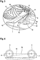
- eine vergrößerte Darstellung des Bereichs des Motorrades an dem die Neigungs- und Nicksensoren angebracht sind, sowie der von den Sensoren bestrichene Bereich,
- Figur 4
- eine schematische Darstellung des "Nickens" eines Kraftfahrzeuges bei einem Bremsmanöver und
- Figur 5
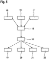
- eine schematische Darstellung des Ablaufs des Verfahrens in einem Ablaufdiagramm.
-
Figur 1 zeigt ein einspuriges Kraftfahrzeug 1. Im dargestellten Ausführungsbeispiel ist das einspurige Kraftfahrzeug ein Motorrad. Das Motorrad weist einen Verbrennungsmotor 2, ein Vorderrad 3 und ein Hinterrad 4 auf. Das Vorderrad 3 ist mittels eines Lenkers 5 relativ zu einer Längsachse 6 des Kraftfahrzeuges 1 auslenkbar. Das Kraftfahrzeug 1 bewegt sich in einer Kurve 7 auf einer Fahrbahn 8. Zwischen dem Hinterrad 4 und dem Vorderrad 3 ist im unteren Bereich des Motorrades eine Sensiervorrichtung 9 angebracht. Die Sensiervorrichtung 9 umfasst zwei Neigungssensoren 10. Die Sensiervorrichtung 9 umfasst ferner zwei Nicksensoren 11. Die Neigungssensoren 10 und Nicksensoren 11 sind besonders gut inFigur 2 erkennbar. - Die Sensiervorrichtung 9 ist als radarbasierte Speed-Vektor-Sensorvorrichtung ausgebildet und weist vier sogenannte Antennenkeulen 12 auf. Jeweils zwei Antennenkeulen 12 werden durch die beiden Neigungssensoren 10 erzeugt. Die zwei anderen Antennenkeulen 12 werden durch die Nicksensoren 11 erzeugt.
- Mittels der Sensiervorrichtung 9 wird eine Messung des Abstandes der Sensiervorrichtung 9 zur Oberfläche der Fahrbahn 8 in vier Richtungen, also in Fahrtrichtung und quer zur Fahrtrichtung vorgenommen.
- Zwei Aufstandsflächen 13 der durch die Neigungssensoren 10 gebildeten Antennenkeulen 12 sind so ausgerichtet, dass eine Verbindungslinie durch diese Aufstandsflächen orthogonal zur Längsrichtung des Fahrzeuges ausgerichtet ist. Diese zwei Antennenkeulen 12, die durch die Nicksensoren 11 hervorgerufen werden, sind in Längsrichtung des Fahrzeuges, also entlang der Längsachse 6 ausgerichtet. Eine Gerade durch die Aufstandsflächen der durch die Nicksensoren 11 hervorgerufenen Antennenkeulen 12 mit der Oberfläche der Fahrbahn 8 ist orthogonal zu einer Geraden durch die Aufstandsflächen der Antennenkeulen 12, wie sie durch die Neigungssensoren 10 hervorgerufen sind, mit der Oberfläche der Fahrbahn 8.
- Die spezielle Anordnung der Neigungssensoren 10 und Nicksensoren 11 ist aus
Figur 2 entnehmbar. Dabei kennzeichnet der Pfeil 13 die Fahrtrichtung des Kraftfahrzeugs 1, die in dem dargestellten Ausführungsbeispiel inFigur 2 gleich der Längsachse 6 des Kraftfahrzeuges 1 entspricht. Die Sensiervorrichtung 9 ist inFigur 2 losgelöst vom restlichen Motorrad dargestellt. Die Antennenkeulen 12 sind nicht dargestellt. Allerdings sind die Aufstandsflächen der Antennenkeulen 12 auf der Oberfläche der Fahrbahn 8 dargestellt und mit den Bezugszeichen 13 versehen. - Zurückkommend zu
Figur 1 ist dort das Kraftfahrzeug 1 in der Kurve 7 fahrend geneigt dargestellt, so dass zwischen einer vertikalen Achse und einer Hochachse 14 durch das Kraftfahrzeug 1 ein Winkel φ vorliegt. Der Winkel φ ist normalerweise geringer als 50° - 60°, im Regelfall 56°. Zwar ist in dem Ausführungsbeispiel nachFigur 1 eine horizontale Fahrbahnoberfläche der Fahrbahn 8 dargestellt, doch ist es möglich, dass die Kurve überhöht ist und somit nicht der Winkel zur Fahrbahnoberfläche, sondern zur Horizontalen relevant bleibt. - Wie in
Figur 3 gut erkennbar, misst eine der Neigungssensoren 10 die Länge I. Die Nicksensoren bestimmen eine Höhe, die über einem entsprechenden Algorithmus zur Höhe h0 umgerechnet werden. - Ferner wird in einer Recheneinrichtung 5, die in den
Figuren 1 bis 4 nicht dargestellt ist, ein Winkel Θk ermittelt. In der Recheneinrichtung 15 wird mit nachfolgendem Algorithmus der Winkel φ bestimmt.
- Auf diese Weise wird der Neigungswinkel mit Hilfe der gemessenen Länge I, also dem Abstand zwischen einem der Neigungssensoren 10 und der Oberfläche der Fahrbahn 8, wobei das Beispiel dargestellt ist, dass eine in Fahrrichtung gesehen rechte Antennenkeule 12 die Basis bildet, bestimmt. Es kann jedoch auch die in Fahrtrichtung gesehen linke Antennenkeule 12 die Basis bilden.
- Da es auch ein Ziel der Erfindung ist, die Kenntnis des Anpressdruckes und der Anpressbedingungen in jeder Fahrsituation zur Verfügung zu haben, also auch bei Bremsvorgängen, die ein "Nicken" hervorrufen, und in Kurven, ist in
Figur 4 die Auswirkung des Bremsens unter Hervorrufung eines "Nickens" dargestellt. Dabei taucht das Kraftfahrzeug in die am Vorderrad 3 angeordneten Federungen ein, wodurch sich im Bereich des Vorderrades 3 das Fahrzeug um den Betrag d absenkt. Die nach und während des Bremsens eingenommene Position eines Längsträgers 16 ist gestrichelt dargestellt. Der Abstand d ist im Regelfall geringer als der Radius r. - In
Figur 5 ist ein Ablaufdiagramm für ein Verfahren gemäß der Erfindung dargestellt. Die Neigungssensoren 10 und Nicksensoren 11 liefern Daten an die Recheneinrichtung 15. Um die Steuer- und Regelgüte zu erhöhen, liefert zumindest ein Schwimmwinkelerfassungssensor 17 zusätzlich Daten an die Recheneinrichtung 15. Der Schwimmwinkelerfassungssensor 17 liefert dabei den Schwimmwinkel, ist jedoch auch in der Lage, entweder den Schräglaufwinkel des Hinterrades und/oder den Schräglaufwinkel des Vorderrades der Recheneinrichtung 15 zuzuführen. Im Schwimmwinkelerfassungssensor 17 findet somit eine Vorverarbeitung der Rohdaten statt. Die Vorverarbeitung der Rohdaten kann jedoch auch in der Recheneinrichtung 15 erfolgen. Es ist möglich, dass der Schwimmwinkelerfassungssensor 17 ein Teil der Sensiervorrichtung 9 ist, die die Neigungssensoren 10 und die Nicksensoren 11 umfasst. Eine entsprechende rechnerische Lösung, um den Schwimmwinkel dann herauszurechnen, ist dann notwendig. - Die Recheneinrichtung 15 liefert ein Signal an eine Steuervorrichtung 18. Dieses Signal ist ein Steuersignal, das durch die Recheneinrichtung 15 in Verarbeitung der zugeführten Daten erzeugt ist. Die Steuervorrichtung 18 wirkt nun auf eines oder mehrere der Steuer- und Regelvorrichtungen, wie eine Kupplungsvorrichtung 19, eine Bremsvorrichtung 20, eine aktive Fahrwerksregelvorrichtung 21 und eine Geschwindigkeitsregelvorrichtung 22. Durch entsprechendes kurzzeitiges Auskuppeln des Motors, kurzzeitiges Bremsen, weicher oder härter Stellen des Fahrwerks und/oder Hinzuführen oder Zurücknehmen von Gas, wird das Fahrzeug dann wieder stabilisiert.
- Gemäß der Erfindung wird nicht mehr nur der Neigungswinkel und der Nickwinkel zum Hervorrufen vorher stabilisierender Brems- und Steuereingriffen genutzt, sondern der Schwimmwinkel und/oder die Schräglaufwinkel. Dadurch wird früher und sicherer das Fahrzeug durch entsprechende Stabilisierungseingriffe bzgl. des fahrdynamischen Verhaltens wieder stabilisiert. Stürze von solchen einspurigen Kraftfahrzeugen 1 und insbesondere der Fahrzeugführer solcher einspuriger Kraftfahrzeuge 1 werden wirkungsvoll verhindert.
- Die Verkehrssicherheit eines entsprechenden einspurigen Kraftfahrzeuges, wie einem Motorrad, wird dadurch erhöht.
Claims (8)
- Verfahren zum Stabilisieren einer Fahrbewegung eines einspurigen Kraftfahrzeugs (1), wie einem Motorrad, bei dem über Neigungssensoren (10) ein Neigungswinkel des Kraftfahrzeugs (1) relativ zu einer Fahrbahn (8) erfasst wird und nach Verarbeitung des Neigungswinkels in einer Recheneinrichtung (15) ein darauf basierendes Steuersignal einer Steuervorrichtung (18) zum Bewirken eines Stabilisierungseingriffes in die Fahrbewegung des Kraftfahrzeuges (1) zugeführt wird und die Geschwindigkeit des Kraftfahrzeugs (1) erfasst und in der Recheneinrichtung (15) mitverarbeitet wird, dadurch gekennzeichnet, dass mittels zumindest eines Schwimmwinkelerfassungssensors (17) der Schwimmwinkel des Kraftfahrzeugs (1) erfasst und in der Steuervorrichtung (18) mitverarbeitet wird.
- Verfahren nach Anspruch 1, wobei der zeitliche Verlauf des Schwimmwinkels erfasst und in der Recheneinrichtung (15) mitverarbeitet wird.
- Verfahren nach einem der Ansprüche 1 bis 2, wobei das Steuersignal ein Entkuppeln, einen Bremseingriff, eine Motorantriebsmomentreduzierung und/oder eine aktive Fahrwerksregelung hervorruft.
- Verfahren nach einem der Ansprüche 1 bis 3, wobei einer der Schwimmwinkelerfassungssensoren (17) einen Schräglaufwinkel an einem Rad des Kraftfahrzeuges (1), vorzugsweise an einem Hinterrad (4) ermittelt und dieser Schräglaufwinkel in der Recheneinrichtung (15) mit verarbeitet wird.
- Verfahren nach einem der Ansprüche 1 bis 4, wobei der Schwimmwinkelerfassungssensor (17) ein Radarsensor ist.
- Verfahren nach einem der Ansprüche 1 bis 5, wobei die Steuervorrichtung (18) das Steuersignal nach Überschreiten eines Grenzwertes auslöst.
- Verfahren nach Anspruch 6, wobei der Grenzwert fest voreingestellt ist.
- Vorrichtung, aufweisend Mittel zum Durchführen des Verfahrens nach einem der vorhergehenden Ansprüche.
Applications Claiming Priority (2)
| Application Number | Priority Date | Filing Date | Title |
|---|---|---|---|
| DE102008001970A DE102008001970A1 (de) | 2008-05-26 | 2008-05-26 | Verfahren zum Stabilisieren von Fahrbewegungen eines einspurigen Kraftfahrzeugs, unter Nutzung des Neigungswinkels und des Schwimmwinkels sowie Vorrichtung dafür |
| PCT/EP2008/067964 WO2009143914A1 (de) | 2008-05-26 | 2008-12-19 | Verfahren und vorrichtung zum stabilisieren von fahrbewegungen eines einspurigen kraftfahrzeugs |
Publications (2)
| Publication Number | Publication Date |
|---|---|
| EP2282926A1 EP2282926A1 (de) | 2011-02-16 |
| EP2282926B1 true EP2282926B1 (de) | 2018-10-17 |
Family
ID=40506493
Family Applications (1)
| Application Number | Title | Priority Date | Filing Date |
|---|---|---|---|
| EP08840783.8A Not-in-force EP2282926B1 (de) | 2008-05-26 | 2008-12-19 | Verfahren und vorrichtung zum stabilisieren von fahrbewegungen eines einspurigen kraftfahrzeugs |
Country Status (5)
| Country | Link |
|---|---|
| US (1) | US20110172881A1 (de) |
| EP (1) | EP2282926B1 (de) |
| JP (1) | JP5285148B2 (de) |
| DE (1) | DE102008001970A1 (de) |
| WO (1) | WO2009143914A1 (de) |
Families Citing this family (16)
| Publication number | Priority date | Publication date | Assignee | Title |
|---|---|---|---|---|
| DE102010003951A1 (de) * | 2010-04-14 | 2011-10-20 | Robert Bosch Gmbh | Verfahren zum Stabilisieren eines Zweirads bei seitlich rutschendem Hinterrad |
| EP2738075B1 (de) * | 2011-07-28 | 2018-03-28 | Yamaha Hatsudoki Kabushiki Kaisha | Haltungskontrollvorrichtung und grätschsitzfahrzeug damit |
| DE102012211963A1 (de) | 2012-07-10 | 2014-01-30 | Robert Bosch Gmbh | Verfahren zur Stabilisierung eines Zweirads bei Kurvenfahrt |
| WO2014017138A1 (ja) | 2012-07-25 | 2014-01-30 | ボッシュ株式会社 | 二輪車の転倒防止方法及び装置 |
| DE102012219935B4 (de) * | 2012-10-31 | 2014-08-28 | Bayerische Motoren Werke Aktiengesellschaft | Verfahren und Baugruppe zur Bestimmung der Abweichung der Fahrzeuglängsachse von einer Bewegungsrichtung eines Motorrades sowie Fahrassistenzsystem und Verfahren zu seiner Betätigung |
| JP5914448B2 (ja) * | 2013-11-01 | 2016-05-11 | ヤマハ発動機株式会社 | 鞍乗り型車両および車輪力取得装置 |
| US9594094B2 (en) | 2014-04-16 | 2017-03-14 | Yamaha Hatsudoki Kabushiki Kaisha | Lateral force estimation system, method of estimating lateral force and vehicle |
| US9897450B2 (en) * | 2015-05-20 | 2018-02-20 | Nokia Technologies Oy | Method and apparatus to obtain differential location information |
| US10060379B2 (en) * | 2015-09-04 | 2018-08-28 | Ford Global Technologies, Llc | Method for a hybrid vehicle |
| DE102016223070A1 (de) * | 2016-11-23 | 2018-05-24 | Robert Bosch Gmbh | Verfahren und Steuergerät zum Erkennen von kritischen Fahrsituationen eines Kraftzweirads |
| DE102017212123B4 (de) * | 2017-07-14 | 2021-03-25 | Robert Bosch Gmbh | Verfahren und Vorrichtung zur Kurvenstabilisierung eines Fahrrads |
| DE112019003302T5 (de) * | 2018-06-29 | 2021-03-18 | Honda Motor Co., Ltd. | Kupplungssteuervorrichtung für ein Fahrzeug des Sattelsitztyps |
| US11027786B2 (en) | 2018-11-20 | 2021-06-08 | Harley-Davidson Motor Company Group, LLC | Gyroscopic rider assist device |
| JP2020093558A (ja) * | 2018-12-10 | 2020-06-18 | ロベルト・ボッシュ・ゲゼルシャフト・ミト・ベシュレンクテル・ハフツングRobert Bosch Gmbh | 制御装置及び制御方法 |
| CN112061279B (zh) * | 2018-12-29 | 2022-02-22 | 深圳得到运通科技有限公司 | 一种电动车安全控制的实现方法 |
| AT527129B1 (de) | 2023-07-03 | 2024-11-15 | Maierhofer Johannes | Unterstützungsvorrichtung für ein Fahrrad und Verfahren zum Betreiben der Unterstützungsvorrichtung |
Citations (1)
| Publication number | Priority date | Publication date | Assignee | Title |
|---|---|---|---|---|
| US7006901B2 (en) * | 2002-11-18 | 2006-02-28 | Wang Everett X | Computerized automated dynamic control system for single-track vehicles |
Family Cites Families (13)
| Publication number | Priority date | Publication date | Assignee | Title |
|---|---|---|---|---|
| DE4117540A1 (de) | 1991-05-29 | 1992-12-03 | Fraunhofer Ges Forschung | Einrichtung zur bestimmung von nick- und rollwinkel bei kraftfahrzeugen |
| US5875408A (en) * | 1995-07-17 | 1999-02-23 | Imra America, Inc. | Automated vehicle guidance system and method for automatically guiding a vehicle |
| JP4640905B2 (ja) * | 2001-04-06 | 2011-03-02 | 本田技研工業株式会社 | ステアリングダンパ装置 |
| DE10235378B4 (de) * | 2002-08-02 | 2015-06-25 | Robert Bosch Gmbh | Verfahren und Vorrichtung zur Bremsenregelung |
| DE10238526A1 (de) * | 2002-08-22 | 2004-03-04 | Robert Bosch Gmbh | Verfahren und Vorrichtung zur Neigungserkennung |
| JP2004082903A (ja) * | 2002-08-28 | 2004-03-18 | Furuki Shinobu | 自立型自動車両 |
| US20040254702A1 (en) * | 2003-06-16 | 2004-12-16 | Mueller Donald Lee | Method and apparatus for sensing a turn on a vehicle |
| DE10350046A1 (de) * | 2003-10-27 | 2005-05-25 | Schubach, Rudolf, Dipl.-Ing. | Vorrichtung zum dynamischen Messen des Rollwinkels von Fahrzeugen |
| CN101005981B (zh) * | 2004-08-06 | 2010-06-16 | 本田技研工业株式会社 | 车辆的控制装置 |
| US7437242B2 (en) * | 2004-09-30 | 2008-10-14 | Victor Company Of Japan, Ltd. | Navigation apparatus |
| DE102005003981B4 (de) * | 2005-01-28 | 2012-03-29 | Bayerische Motoren Werke Aktiengesellschaft | Verfahren zur Antriebsmomentregelung bei einem einspurigen Kraftfahrzeug |
| JP4230483B2 (ja) * | 2005-11-14 | 2009-02-25 | マイコム株式会社 | 自動二輪車 |
| US8494747B2 (en) * | 2007-03-16 | 2013-07-23 | Continental Teves Ag & Co. Ohg | Method and device for stabilizing a single-track motor vehicle |
-
2008
- 2008-05-26 DE DE102008001970A patent/DE102008001970A1/de not_active Withdrawn
- 2008-12-19 US US12/736,854 patent/US20110172881A1/en not_active Abandoned
- 2008-12-19 WO PCT/EP2008/067964 patent/WO2009143914A1/de not_active Ceased
- 2008-12-19 JP JP2011510848A patent/JP5285148B2/ja not_active Expired - Fee Related
- 2008-12-19 EP EP08840783.8A patent/EP2282926B1/de not_active Not-in-force
Patent Citations (1)
| Publication number | Priority date | Publication date | Assignee | Title |
|---|---|---|---|---|
| US7006901B2 (en) * | 2002-11-18 | 2006-02-28 | Wang Everett X | Computerized automated dynamic control system for single-track vehicles |
Also Published As
| Publication number | Publication date |
|---|---|
| JP5285148B2 (ja) | 2013-09-11 |
| WO2009143914A1 (de) | 2009-12-03 |
| US20110172881A1 (en) | 2011-07-14 |
| EP2282926A1 (de) | 2011-02-16 |
| JP2011520703A (ja) | 2011-07-21 |
| DE102008001970A1 (de) | 2009-12-03 |
Similar Documents
| Publication | Publication Date | Title |
|---|---|---|
| EP2282926A1 (de) | Verfahren und vorrichtung zum stabilisieren von fahrbewegungen eines einspurigen kraftfahrzeugs | |
| EP2558340B1 (de) | Verfahren zum stabilisieren eines zweirads bei seitlich rutschendem hinterrad | |
| DE102012020074B4 (de) | Spurwechsel-Unterstützungssystem für Fahrzeuge und Spurwechsel- Unterstützungsverfahren hierfür | |
| DE60318919T2 (de) | Fahrzeugsteuervorrichtung mit Servolenkung | |
| EP2358574B1 (de) | Verfahren und vorrichtung zum bestimmen des schräglagewinkels eines zweiradfahrzeugs | |
| EP2949531B1 (de) | Verfahren und fahrerassistenzsystem zur ermittlung fahrdynamischer zustände eines nutzfahrzeugs | |
| DE112016002910B4 (de) | Spurhaltevorrichtung | |
| DE102010033381B4 (de) | Verfahren und System zum Steuern eines Fahrzeugs und eines Anhängers | |
| EP2616292B1 (de) | Verfahren zur bremsmomentenregelung in einem zweiradfahrzeug bei schräglagenfahrt | |
| DE10235378B4 (de) | Verfahren und Vorrichtung zur Bremsenregelung | |
| DE102005009814B4 (de) | Fahrzeugzustands-Erfassungssystem und -verfahren | |
| DE102018129823A1 (de) | Überwachen der Ausrichtung des Fahrzeugaufhängungssystems | |
| DE102011017103B4 (de) | Systeme und verfahren zum steuern eines fahrzeugsentlang einer strasse mit einem strassenbankett | |
| DE10126315C2 (de) | Straßenreibzahl-Schätzvorrichtung für ein Kraftfahrzeug | |
| DE102017005456B4 (de) | Gelenkfahrzeug | |
| DE112019001595B4 (de) | Steigungsschätzvorrichtung und fahrzeug | |
| EP3442839B1 (de) | Verfahren und vorrichtung zum bestimmen einer sicherheitskritischen gierbewegung eines fahrzeugs | |
| EP3544868A1 (de) | Verfahren und steuergerät zum erkennen von kritischen fahrsituationen eines kraftzweirads | |
| DE102013009399A1 (de) | Verfahren zur Erkennung einer kritischen Fahrsituation eines Fahrzeugs | |
| WO2008077670A1 (de) | Verfahren und vorrichtung zum ermitteln einer reibkennzahl | |
| DE102014009115B4 (de) | Lenksteuervorrichtung und- verfahren | |
| DE102006002399A1 (de) | Verfahren und Vorrichtung zur Regelung der Brems- und/oder der Antriebskräfte eines einspurigen Fahrzeugs | |
| DE102004048531A1 (de) | Vorrichtung und Verfahren zur Stabilisierung eines Fahrzeugs | |
| DE102015207755A1 (de) | Gerät zum Regeln/Steuern eines Fahrens | |
| EP3148856B1 (de) | Verfahren zur einstellung einer schlupfschwelle und fahrdynamik-regeleinrichtung |
Legal Events
| Date | Code | Title | Description |
|---|---|---|---|
| PUAI | Public reference made under article 153(3) epc to a published international application that has entered the european phase |
Free format text: ORIGINAL CODE: 0009012 |
|
| 17P | Request for examination filed |
Effective date: 20101227 |
|
| AK | Designated contracting states |
Kind code of ref document: A1 Designated state(s): AT BE BG CH CY CZ DE DK EE ES FI FR GB GR HR HU IE IS IT LI LT LU LV MC MT NL NO PL PT RO SE SI SK TR |
|
| AX | Request for extension of the european patent |
Extension state: AL BA MK RS |
|
| DAX | Request for extension of the european patent (deleted) | ||
| GRAP | Despatch of communication of intention to grant a patent |
Free format text: ORIGINAL CODE: EPIDOSNIGR1 |
|
| INTG | Intention to grant announced |
Effective date: 20180719 |
|
| GRAS | Grant fee paid |
Free format text: ORIGINAL CODE: EPIDOSNIGR3 |
|
| GRAA | (expected) grant |
Free format text: ORIGINAL CODE: 0009210 |
|
| AK | Designated contracting states |
Kind code of ref document: B1 Designated state(s): AT BE BG CH CY CZ DE DK EE ES FI FR GB GR HR HU IE IS IT LI LT LU LV MC MT NL NO PL PT RO SE SI SK TR |
|
| REG | Reference to a national code |
Ref country code: GB Ref legal event code: FG4D Free format text: NOT ENGLISH |
|
| REG | Reference to a national code |
Ref country code: CH Ref legal event code: EP |
|
| REG | Reference to a national code |
Ref country code: IE Ref legal event code: FG4D Free format text: LANGUAGE OF EP DOCUMENT: GERMAN |
|
| REG | Reference to a national code |
Ref country code: DE Ref legal event code: R096 Ref document number: 502008016398 Country of ref document: DE Ref country code: AT Ref legal event code: REF Ref document number: 1053664 Country of ref document: AT Kind code of ref document: T Effective date: 20181115 |
|
| REG | Reference to a national code |
Ref country code: NL Ref legal event code: MP Effective date: 20181017 |
|
| REG | Reference to a national code |
Ref country code: LT Ref legal event code: MG4D |
|
| PG25 | Lapsed in a contracting state [announced via postgrant information from national office to epo] |
Ref country code: NL Free format text: LAPSE BECAUSE OF FAILURE TO SUBMIT A TRANSLATION OF THE DESCRIPTION OR TO PAY THE FEE WITHIN THE PRESCRIBED TIME-LIMIT Effective date: 20181017 |
|
| PG25 | Lapsed in a contracting state [announced via postgrant information from national office to epo] |
Ref country code: BG Free format text: LAPSE BECAUSE OF FAILURE TO SUBMIT A TRANSLATION OF THE DESCRIPTION OR TO PAY THE FEE WITHIN THE PRESCRIBED TIME-LIMIT Effective date: 20190117 Ref country code: PL Free format text: LAPSE BECAUSE OF FAILURE TO SUBMIT A TRANSLATION OF THE DESCRIPTION OR TO PAY THE FEE WITHIN THE PRESCRIBED TIME-LIMIT Effective date: 20181017 Ref country code: HR Free format text: LAPSE BECAUSE OF FAILURE TO SUBMIT A TRANSLATION OF THE DESCRIPTION OR TO PAY THE FEE WITHIN THE PRESCRIBED TIME-LIMIT Effective date: 20181017 Ref country code: FI Free format text: LAPSE BECAUSE OF FAILURE TO SUBMIT A TRANSLATION OF THE DESCRIPTION OR TO PAY THE FEE WITHIN THE PRESCRIBED TIME-LIMIT Effective date: 20181017 Ref country code: LT Free format text: LAPSE BECAUSE OF FAILURE TO SUBMIT A TRANSLATION OF THE DESCRIPTION OR TO PAY THE FEE WITHIN THE PRESCRIBED TIME-LIMIT Effective date: 20181017 Ref country code: LV Free format text: LAPSE BECAUSE OF FAILURE TO SUBMIT A TRANSLATION OF THE DESCRIPTION OR TO PAY THE FEE WITHIN THE PRESCRIBED TIME-LIMIT Effective date: 20181017 Ref country code: ES Free format text: LAPSE BECAUSE OF FAILURE TO SUBMIT A TRANSLATION OF THE DESCRIPTION OR TO PAY THE FEE WITHIN THE PRESCRIBED TIME-LIMIT Effective date: 20181017 Ref country code: IS Free format text: LAPSE BECAUSE OF FAILURE TO SUBMIT A TRANSLATION OF THE DESCRIPTION OR TO PAY THE FEE WITHIN THE PRESCRIBED TIME-LIMIT Effective date: 20190217 Ref country code: NO Free format text: LAPSE BECAUSE OF FAILURE TO SUBMIT A TRANSLATION OF THE DESCRIPTION OR TO PAY THE FEE WITHIN THE PRESCRIBED TIME-LIMIT Effective date: 20190117 |
|
| PG25 | Lapsed in a contracting state [announced via postgrant information from national office to epo] |
Ref country code: PT Free format text: LAPSE BECAUSE OF FAILURE TO SUBMIT A TRANSLATION OF THE DESCRIPTION OR TO PAY THE FEE WITHIN THE PRESCRIBED TIME-LIMIT Effective date: 20190217 Ref country code: GR Free format text: LAPSE BECAUSE OF FAILURE TO SUBMIT A TRANSLATION OF THE DESCRIPTION OR TO PAY THE FEE WITHIN THE PRESCRIBED TIME-LIMIT Effective date: 20190118 Ref country code: SE Free format text: LAPSE BECAUSE OF FAILURE TO SUBMIT A TRANSLATION OF THE DESCRIPTION OR TO PAY THE FEE WITHIN THE PRESCRIBED TIME-LIMIT Effective date: 20181017 |
|
| REG | Reference to a national code |
Ref country code: DE Ref legal event code: R119 Ref document number: 502008016398 Country of ref document: DE |
|
| PG25 | Lapsed in a contracting state [announced via postgrant information from national office to epo] |
Ref country code: DK Free format text: LAPSE BECAUSE OF FAILURE TO SUBMIT A TRANSLATION OF THE DESCRIPTION OR TO PAY THE FEE WITHIN THE PRESCRIBED TIME-LIMIT Effective date: 20181017 Ref country code: IT Free format text: LAPSE BECAUSE OF FAILURE TO SUBMIT A TRANSLATION OF THE DESCRIPTION OR TO PAY THE FEE WITHIN THE PRESCRIBED TIME-LIMIT Effective date: 20181017 Ref country code: CZ Free format text: LAPSE BECAUSE OF FAILURE TO SUBMIT A TRANSLATION OF THE DESCRIPTION OR TO PAY THE FEE WITHIN THE PRESCRIBED TIME-LIMIT Effective date: 20181017 |
|
| REG | Reference to a national code |
Ref country code: CH Ref legal event code: PL |
|
| PLBE | No opposition filed within time limit |
Free format text: ORIGINAL CODE: 0009261 |
|
| STAA | Information on the status of an ep patent application or granted ep patent |
Free format text: STATUS: NO OPPOSITION FILED WITHIN TIME LIMIT |
|
| PG25 | Lapsed in a contracting state [announced via postgrant information from national office to epo] |
Ref country code: MC Free format text: LAPSE BECAUSE OF FAILURE TO SUBMIT A TRANSLATION OF THE DESCRIPTION OR TO PAY THE FEE WITHIN THE PRESCRIBED TIME-LIMIT Effective date: 20181017 Ref country code: SK Free format text: LAPSE BECAUSE OF FAILURE TO SUBMIT A TRANSLATION OF THE DESCRIPTION OR TO PAY THE FEE WITHIN THE PRESCRIBED TIME-LIMIT Effective date: 20181017 Ref country code: EE Free format text: LAPSE BECAUSE OF FAILURE TO SUBMIT A TRANSLATION OF THE DESCRIPTION OR TO PAY THE FEE WITHIN THE PRESCRIBED TIME-LIMIT Effective date: 20181017 Ref country code: LU Free format text: LAPSE BECAUSE OF NON-PAYMENT OF DUE FEES Effective date: 20181219 Ref country code: RO Free format text: LAPSE BECAUSE OF FAILURE TO SUBMIT A TRANSLATION OF THE DESCRIPTION OR TO PAY THE FEE WITHIN THE PRESCRIBED TIME-LIMIT Effective date: 20181017 |
|
| REG | Reference to a national code |
Ref country code: IE Ref legal event code: MM4A |
|
| 26N | No opposition filed |
Effective date: 20190718 |
|
| GBPC | Gb: european patent ceased through non-payment of renewal fee |
Effective date: 20190117 |
|
| REG | Reference to a national code |
Ref country code: BE Ref legal event code: MM Effective date: 20181231 |
|
| PG25 | Lapsed in a contracting state [announced via postgrant information from national office to epo] |
Ref country code: DE Free format text: LAPSE BECAUSE OF NON-PAYMENT OF DUE FEES Effective date: 20190702 Ref country code: FR Free format text: LAPSE BECAUSE OF NON-PAYMENT OF DUE FEES Effective date: 20181231 Ref country code: SI Free format text: LAPSE BECAUSE OF FAILURE TO SUBMIT A TRANSLATION OF THE DESCRIPTION OR TO PAY THE FEE WITHIN THE PRESCRIBED TIME-LIMIT Effective date: 20181017 Ref country code: IE Free format text: LAPSE BECAUSE OF NON-PAYMENT OF DUE FEES Effective date: 20181219 |
|
| PG25 | Lapsed in a contracting state [announced via postgrant information from national office to epo] |
Ref country code: BE Free format text: LAPSE BECAUSE OF NON-PAYMENT OF DUE FEES Effective date: 20181231 |
|
| PG25 | Lapsed in a contracting state [announced via postgrant information from national office to epo] |
Ref country code: CH Free format text: LAPSE BECAUSE OF NON-PAYMENT OF DUE FEES Effective date: 20181231 Ref country code: LI Free format text: LAPSE BECAUSE OF NON-PAYMENT OF DUE FEES Effective date: 20181231 Ref country code: GB Free format text: LAPSE BECAUSE OF NON-PAYMENT OF DUE FEES Effective date: 20190117 |
|
| PG25 | Lapsed in a contracting state [announced via postgrant information from national office to epo] |
Ref country code: MT Free format text: LAPSE BECAUSE OF FAILURE TO SUBMIT A TRANSLATION OF THE DESCRIPTION OR TO PAY THE FEE WITHIN THE PRESCRIBED TIME-LIMIT Effective date: 20181017 |
|
| REG | Reference to a national code |
Ref country code: AT Ref legal event code: MM01 Ref document number: 1053664 Country of ref document: AT Kind code of ref document: T Effective date: 20181219 |
|
| PG25 | Lapsed in a contracting state [announced via postgrant information from national office to epo] |
Ref country code: TR Free format text: LAPSE BECAUSE OF FAILURE TO SUBMIT A TRANSLATION OF THE DESCRIPTION OR TO PAY THE FEE WITHIN THE PRESCRIBED TIME-LIMIT Effective date: 20181017 |
|
| PG25 | Lapsed in a contracting state [announced via postgrant information from national office to epo] |
Ref country code: AT Free format text: LAPSE BECAUSE OF NON-PAYMENT OF DUE FEES Effective date: 20181219 |
|
| PG25 | Lapsed in a contracting state [announced via postgrant information from national office to epo] |
Ref country code: CY Free format text: LAPSE BECAUSE OF FAILURE TO SUBMIT A TRANSLATION OF THE DESCRIPTION OR TO PAY THE FEE WITHIN THE PRESCRIBED TIME-LIMIT Effective date: 20181017 Ref country code: HU Free format text: LAPSE BECAUSE OF FAILURE TO SUBMIT A TRANSLATION OF THE DESCRIPTION OR TO PAY THE FEE WITHIN THE PRESCRIBED TIME-LIMIT; INVALID AB INITIO Effective date: 20081219 |