EP2282514A1 - Recording apparatus and processing method executed by the recording apparatus - Google Patents
Recording apparatus and processing method executed by the recording apparatus Download PDFInfo
- Publication number
- EP2282514A1 EP2282514A1 EP10171976A EP10171976A EP2282514A1 EP 2282514 A1 EP2282514 A1 EP 2282514A1 EP 10171976 A EP10171976 A EP 10171976A EP 10171976 A EP10171976 A EP 10171976A EP 2282514 A1 EP2282514 A1 EP 2282514A1
- Authority
- EP
- European Patent Office
- Prior art keywords
- raster
- data
- recording
- rasterization
- multivalued data
- Prior art date
- Legal status (The legal status is an assumption and is not a legal conclusion. Google has not performed a legal analysis and makes no representation as to the accuracy of the status listed.)
- Granted
Links
Images


Classifications
-
- H—ELECTRICITY
- H04—ELECTRIC COMMUNICATION TECHNIQUE
- H04N—PICTORIAL COMMUNICATION, e.g. TELEVISION
- H04N1/00—Scanning, transmission or reproduction of documents or the like, e.g. facsimile transmission; Details thereof
- H04N1/40—Picture signal circuits
- H04N1/405—Halftoning, i.e. converting the picture signal of a continuous-tone original into a corresponding signal showing only two levels
-
- B—PERFORMING OPERATIONS; TRANSPORTING
- B41—PRINTING; LINING MACHINES; TYPEWRITERS; STAMPS
- B41J—TYPEWRITERS; SELECTIVE PRINTING MECHANISMS, i.e. MECHANISMS PRINTING OTHERWISE THAN FROM A FORME; CORRECTION OF TYPOGRAPHICAL ERRORS
- B41J19/00—Character- or line-spacing mechanisms
- B41J19/14—Character- or line-spacing mechanisms with means for effecting line or character spacing in either direction
- B41J19/142—Character- or line-spacing mechanisms with means for effecting line or character spacing in either direction with a reciprocating print head printing in both directions across the paper width
-
- H—ELECTRICITY
- H04—ELECTRIC COMMUNICATION TECHNIQUE
- H04N—PICTORIAL COMMUNICATION, e.g. TELEVISION
- H04N1/00—Scanning, transmission or reproduction of documents or the like, e.g. facsimile transmission; Details thereof
- H04N1/04—Scanning arrangements, i.e. arrangements for the displacement of active reading or reproducing elements relative to the original or reproducing medium, or vice versa
- H04N1/12—Scanning arrangements, i.e. arrangements for the displacement of active reading or reproducing elements relative to the original or reproducing medium, or vice versa using the sheet-feed movement or the medium-advance or the drum-rotation movement as the slow scanning component, e.g. arrangements for the main-scanning
- H04N1/126—Arrangements for the main scanning
- H04N1/128—Arrangements for the main scanning using a scanning head arranged for linear reciprocating motion
-
- H—ELECTRICITY
- H04—ELECTRIC COMMUNICATION TECHNIQUE
- H04N—PICTORIAL COMMUNICATION, e.g. TELEVISION
- H04N1/00—Scanning, transmission or reproduction of documents or the like, e.g. facsimile transmission; Details thereof
- H04N1/32—Circuits or arrangements for control or supervision between transmitter and receiver or between image input and image output device, e.g. between a still-image camera and its memory or between a still-image camera and a printer device
- H04N1/32358—Circuits or arrangements for control or supervision between transmitter and receiver or between image input and image output device, e.g. between a still-image camera and its memory or between a still-image camera and a printer device using picture signal storage, e.g. at transmitter
- H04N1/32491—Circuits or arrangements for control or supervision between transmitter and receiver or between image input and image output device, e.g. between a still-image camera and its memory or between a still-image camera and a printer device using picture signal storage, e.g. at transmitter alternate storage in and retrieval from two parallel memories, e.g. using ping-pong buffers
-
- H—ELECTRICITY
- H04—ELECTRIC COMMUNICATION TECHNIQUE
- H04N—PICTORIAL COMMUNICATION, e.g. TELEVISION
- H04N1/00—Scanning, transmission or reproduction of documents or the like, e.g. facsimile transmission; Details thereof
- H04N1/40—Picture signal circuits
- H04N1/405—Halftoning, i.e. converting the picture signal of a continuous-tone original into a corresponding signal showing only two levels
- H04N1/4055—Halftoning, i.e. converting the picture signal of a continuous-tone original into a corresponding signal showing only two levels producing a clustered dots or a size modulated halftone pattern
-
- H—ELECTRICITY
- H04—ELECTRIC COMMUNICATION TECHNIQUE
- H04N—PICTORIAL COMMUNICATION, e.g. TELEVISION
- H04N1/00—Scanning, transmission or reproduction of documents or the like, e.g. facsimile transmission; Details thereof
- H04N1/04—Scanning arrangements, i.e. arrangements for the displacement of active reading or reproducing elements relative to the original or reproducing medium, or vice versa
- H04N1/19—Scanning arrangements, i.e. arrangements for the displacement of active reading or reproducing elements relative to the original or reproducing medium, or vice versa using multi-element arrays
- H04N1/191—Scanning arrangements, i.e. arrangements for the displacement of active reading or reproducing elements relative to the original or reproducing medium, or vice versa using multi-element arrays the array comprising a one-dimensional array, or a combination of one-dimensional arrays, or a substantially one-dimensional array, e.g. an array of staggered elements
- H04N1/1911—Simultaneously or substantially simultaneously scanning picture elements on more than one main scanning line, e.g. scanning in swaths
-
- H—ELECTRICITY
- H04—ELECTRIC COMMUNICATION TECHNIQUE
- H04N—PICTORIAL COMMUNICATION, e.g. TELEVISION
- H04N2201/00—Indexing scheme relating to scanning, transmission or reproduction of documents or the like, and to details thereof
- H04N2201/04—Scanning arrangements
- H04N2201/0402—Arrangements not specific to a particular one of the scanning methods covered by groups H04N1/04 - H04N1/207
- H04N2201/0466—Selectively scanning in one or the other of two opposite directions, e.g. in the forward or the reverse direction
- H04N2201/0468—Scanning in both of the two directions, e.g. during the forward and return movements
-
- H—ELECTRICITY
- H04—ELECTRIC COMMUNICATION TECHNIQUE
- H04N—PICTORIAL COMMUNICATION, e.g. TELEVISION
- H04N2201/00—Indexing scheme relating to scanning, transmission or reproduction of documents or the like, and to details thereof
- H04N2201/32—Circuits or arrangements for control or supervision between transmitter and receiver or between image input and image output device, e.g. between a still-image camera and its memory or between a still-image camera and a printer device
- H04N2201/3285—Circuits or arrangements for control or supervision between transmitter and receiver or between image input and image output device, e.g. between a still-image camera and its memory or between a still-image camera and a printer device using picture signal storage, e.g. at transmitter
- H04N2201/329—Storage of less than a complete document page or image frame
- H04N2201/3294—Storage of less than a complete document page or image frame of several complete lines, e.g. a band of data
Landscapes
- Engineering & Computer Science (AREA)
- Multimedia (AREA)
- Signal Processing (AREA)
- Ink Jet (AREA)
- Record Information Processing For Printing (AREA)
- Facsimile Image Signal Circuits (AREA)
- Color, Gradation (AREA)
Abstract
Description
- The present invention relates to a recording apparatus, a controller for the recording apparatus and a processing method executed by the recording apparatus.
- A conventional recording apparatus executes recording of an image on a recording medium. When data regarding an image to be recorded is received from a host apparatus, the conventional recording apparatus rasterizes the received data into binary bitmap data. In addition, the recording apparatus transfers the bitmap data to a recording head to execute the recording process according to the bitmap.
- As a method for rasterizing multivalued data (e.g. density level values from 0 to 255 for each pixel) into bitmap data, a conventional method generates and uses a rasterization table (i.e. a dot matrix) for the gradation (e.g. colour-ranking or shade-ranking, also referred to as density-ranking) of each pixel. In executing rasterization described above, if only a fixed rasterization table (of a single dot matrix associated with each gradation (or density) level) is provided for the gradation of pixels and if the pixels have the same gradation, then the same rasterization pattern is obtained (i.e. a series of pixels with the same colour or shade using the same dot matrix is printed). In executing rasterization using a fixed pattern, banding or image unevenness may occur due to smear on nozzles or unevenly discharged ink because smear or unevenness is more visible when a regular pattern is used because of the conspicuousness of the regular pattern.
- In order to address the above-described problem, a conventional method generates and uses a plurality of dot matrices for the gradation of each pixel. The conventional method like this selects one from among the plurality of matrices to apply to each pixel (even if the pixels are of the same density). In this case, the pattern corresponding to each gradation is not fixed. Accordingly, the influence from the smear on the nozzles may not easily arise. Therefore, the conventional method is capable of reducing or suppressing visual unevenness that may otherwise occur due to unevenness of the mechanical accuracy of a recording head. In other words, a smoother transition of colour or shade from one pixel to the next in a raster is possible because the pixel colours or shades are determined based on one of several possible overall dot matrices.
- Various methods for selecting one from among a plurality of dot matrices have been conventionally proposed. Japanese Patent Application Laid-Open No.
09-046522 - However, if the method discussed in Japanese Patent Application Laid-Open No.
09-046522 - In addition, a recording apparatus may include a plurality of recording modes, such as a single-pass recording mode and a multipass recording mode, either mode in which both single direction recording and bidirectional recording can be executed. Accordingly, in order to appropriately select a dot matrix, it is necessary also to consider these recording modes.
- In the method discussed in Japanese Patent Application Laid-Open No.
09-046522 - On the other hand, it is desired by the market that recording is executed at a high speed and that costs of manufacture of a recording apparatus is reduced. Therefore, it is desirable to reduce the time taken in executing rasterization processing. In addition, it is desirable to simplify the circuitry configuration of a recording apparatus.
- According to an aspect of the present invention, there is provided a recording apparatus as specified in
claims 1 to 5. According to a second aspect of the invention, there is provided a processing method according toclaims 6 and 7. - Further features and aspects of the present invention will become apparent from the following detailed description of exemplary embodiments with reference to the attached drawings.
- The invention will hereinbelow be described, purely by way of example, with reference to the following figures.
-
Fig. 1 is a perspective view illustrating an example of an external appearance and an exemplary configuration of an inkjet recording apparatus according to an exemplary embodiment of the present invention. -
Fig. 2 illustrates an exemplary functional configuration of the recording apparatus illustrated inFig. 1 . -
Fig. 3 illustrates an exemplary functional configuration of a controller illustrated inFig. 2 . -
Fig. 4 is a flow chart illustrating an example of processing executed by the recording apparatus illustrated inFig. 1 . -
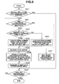
Fig. 5 is a flow chart illustrating an example of data rasterization processing, which is executed in step S107 illustrated inFig. 4 . -
Fig. 6 is a flow chart illustrating an example of multipass recording and rasterization processing, which is executed in step S207 illustrated inFig. 5 . -
Fig. 7 illustrates an exemplary functional configuration of a controller according to a second exemplary embodiment of the present invention. -
Fig. 8 is a flow chart illustrating an exemplary flow of processing executed by the recording apparatus according to the second exemplary embodiment of the present invention. -
Fig. 9 is a flow chart illustrating an example of data rasterization processing, which is executed in step S107, according to the second exemplary embodiment of the present invention. -
Figs. 10A and 10B schematically illustrate an example of received data, which is transmitted from a receiving buffer provided in the controller to a raster control unit. -
Fig. 11 illustrates an example of a rasterization pattern. -
Fig. 12A illustrates an example of raster data.Fig. 12B illustrates an example of a method for storing information about an empty raster.Fig. 12C illustrates an example of a multivalued data storage unit. -
Fig. 13A illustrates an example of allocation of a pattern of multivalued data.Fig. 13B illustrates an example of a method for storing information about a left edge and a right edge of multivalued data of a raster. - DESCRIPTION OF THE EMBODIMENTS
- A recording apparatus according to a first exemplary embodiment of the present invention, which employs an inkjet recording method, will be described in detail below. As the recording apparatus according to an exemplary embodiment of the present invention, it is useful to use a single function printer having a recording (i.e. printing) function only. It is also useful if a multifunction printer having a plurality of functions, such as a recording function, a facsimile transmission function, and a scanner function, is used as the recording apparatus according to an exemplary embodiment of the present invention. Furthermore, the present invention can be implemented in a manufacturing apparatus configured to manufacture a colour filter, an electronic device or an optical device by using a predetermined recording method.
- In the following description, the term "recording" or to "record" includes an operation or processing for generating information, such as text, a graphic, an image, a pattern, or a structure on a recording medium, or processing information to be stored on a recording medium. The recordal may be performed regardless of whether the information being recorded has become visible so that a user can visually recognize the information.
- In addition, in the following description, the term "recording medium" refers to a medium on which the image or pattern is recorded. The recording medium is generally made of a material capable of receiving ink, such as paper, cloth, a plastic film, a metal plate, a glass material, a ceramic material, resin, wood, leather, etc. The term "ink" refers to a liquid, gel or similar that can be used in generating the image or pattern on a recording medium. The processing of the ink includes processing executed for solidification or insolubilization (e.g. coming out of solution) of a colorant included in the ink to be provided on a recording medium.
-
Fig. 1 is a perspective view of an exemplary configuration of an inkjet recording apparatus. - Referring to
Fig. 1 , an inkjet recording apparatus (hereinafter simply referred to as a "recording apparatus") 1 includes acarriage 2. Thecarriage 2 includes an inkjet recording head (hereinafter simply referred to as a "recording head") 3. Therecording head 3 discharges ink by using the inkjet recording method to execute recording. During recording, thecarriage 2 reciprocatingly moves along a carriage supporting member 7 in directions indicated by the arrow A. - The
recording apparatus 1 feeds a recording medium P, such as a sheet of recording paper, via a paper feed mechanism 5, to a recording position. At the timing the recording medium P is fed to the recording position, therecording head 3 discharges ink onto the recording medium P. Thus, therecording apparatus 1 executes recording on the recording medium P. - The
carriage 2 of therecording apparatus 1 includes anink cartridge 6 as well as therecording head 3. Theink cartridge 6 contains ink to be supplied to therecording head 3. Theink cartridge 6 is detachably mounted on thecarriage 2. - The
recording apparatus 1 illustrated inFig. 1 is capable of executing colour recording. Accordingly, four ink cartridges containing magenta (M), cyan (C), yellow (Y), and black (k) inks are mounted on thecarriage 2. The four ink cartridges can be mounted and dismounted separately and independently from one another. - The
recording head 3 according to the present exemplary embodiment employs an inkjet printing method, in which ink is discharged by using thermal energy. Accordingly, therecording head 3 includes an electrothermal conversion member. The electrothermal conversion member is provided to each ink discharge port. Pulse voltage is applied to a corresponding electrothermal conversion member according to a recording signal. Then, ink is discharged from a corresponding ink discharge port. -
Fig. 2 illustrates an exemplary functional configuration of therecording apparatus 1 illustrated inFig. 1 . Therecording apparatus 1 stores a plurality of rasterization tables (dot matrices) in correspondence with each gradation of multivalued data. Therecording apparatus 1 rasterizes the multivalued data into bitmap data by using any one of the plurality of rasterization tables. Furthermore, therecording apparatus 1 executes gradation recording according to the bitmap data. By "gradation", what is understood is that the colour or density of a pixel will be graded from light to dark/bright (low to high density or light to bright colour). The density level may be graded from 0 to 255 according to the number of dots within a dot matrix that determines the gradation of the pixel. - Every time data having the same gradation is processed, the
recording apparatus 1 according to the present exemplary embodiment changes the rasterization table to be used for rasterization on the gradation. Accordingly, different rasterization patterns are generated for a plurality of pieces of data having the same gradation. - In the example illustrated in
Fig. 2 , acontroller 600 includes a micro processing unit (MPU) 601, a read-only memory (ROM) 602, an application specific integrated circuit (ASIC) 603, a random access memory (RAM) 604, asystem bus 605, and an analogue-to-digital (A/D)converter 606. In the present exemplary embodiment, theROM 602 stores a program corresponding to the following control sequence, a predetermined table, and other fixed data. TheASIC 603 controls a carriage motor M1 via acarriage motor driver 640 and a conveyance motor M2 via aconveyance motor driver 642. In addition, theASIC 603 generates a control signal, which is used for controlling therecording head 3. - The
RAM 604 is used as a work area for rasterization of image data and for executing a program thereon. TheMPU 601, theASIC 603, and theRAM 604 are in communication with one another via thesystem bus 605 to transmit and receive data therebetween. The A/D converter 606 converts an analogue signal, which is input by sensors, into a digital signal (i.e., executes A/D conversion on the analogue signal) and supplies the digital signal generated by the conversion to theMPU 601. - A
switch group 620 includes apower switch 621, aprint switch 622, and arecovery switch 623. Asensor group 630 includes sensors for detecting the state of therecording apparatus 1, such as aposition sensor 631 and atemperature sensor 632. - During scanning and recording by the
recording head 3, theASIC 603, while directly accessing a storage area of theRAM 604, transfers dot data (binary data) for driving a recording element (e.g. a discharge heater) to therecording head 3. - The carriage motor M1 is a drive source for causing the
carriage 2 to reciprocatingly move and scan in the directions indicated by arrow A illustrated inFig. 1 . Acarriage motor driver 640 controls driving of the carriage motor M1. The conveyance motor M2 is a drive source for conveying the recording medium P. Aconveyance motor driver 642 controls driving of the conveyance motor M2. - A recording head control unit 644 (shown in
Fig. 3 ) controls therecording head 3 according to recording data input from thecontroller 600. Therecording head 3 is caused to move and scan in a direction perpendicular to the conveyance direction of the recording medium P (hereinafter simply referred to as a "scanning direction"). - The recording by the
recording head 3 is executed in the single-pass recording mode (both executing single-direction recording and bidirectional recording can be executed) or the multipass recording mode (both single-direction recording and bidirectional recording can be executed). - In the example illustrated in
Fig. 2 , acomputer 610 is a source of supplying image data (alternatively, a reader apparatus configured to read an image or a digital camera). Thecomputer 610 is simply referred to as a host apparatus. - Between the
host apparatus 610 and therecording apparatus 1, image data, a command, and a status signal are transmitted and received via an interface (I/F) 611. The image data is input as data having a format of a raster (hereinafter simply referred to as "raster data"). -
Fig. 3 illustrates an exemplary functional configuration of thecontroller 600 illustrated inFig. 2 .
Referring toFig. 3 , thecontroller 600 includes or is connected to an I/F 611 for communicating with thehost apparatus 610. The controller includes a receivingbuffer 102, araster control unit 103, a multivalueddata storage unit 104, asecond storage unit 105, afirst storage unit 106, and a rasterization control unit (a generation unit) 101. In addition, thecontroller 600 includes a recordingdirection storage unit 108, a rasterizationtable storage unit 109, aselector 110, and an initialvalue storage unit 111. - The I/
F 611 receives raster data from thehost apparatus 610. The receivingbuffer 102 temporarily stores the data received by the I/F 611 from thehost apparatus 610 as received data. The data stored on the receivingbuffer 102 includes raster data. In the present exemplary embodiment, the raster data may also be simply referred to as a "raster". The raster data (each raster) stored on the receivingbuffer 102 is transmitted to theraster control unit 103. - Now, the raster data will be described in detail below with reference to
Figs. 10A and 10B . Referring toFig. 10A , in the raster data, quantized data (multivalued data) 201 is arranged in the scanning direction (indicated by arrow A inFig. 10A ) of the recording head. Theleading edge 205 of each raster corresponds to the left edge of the recording medium while the trailingedge 206 of each raster corresponds to the right edge of the recording medium. Raster data (202, 203, and 204) is arranged in a direction perpendicular to the scanning direction A, though each raster extends along the scanning direction A. The direction of conveyance of the recording medium and thus of the raster data is indicated by arrow B inFig. 10A . - A raster is made up of a plurality of pixels, each with a density value. The density value of each pixel may also be known as its gradation. As will be described later, there are several ways in which a bitmap may be built up for the same density value of a pixel. As a raster is made up of a plurality of pixels, it comprises a
first pixel 205 at its leading edge and alast pixel 206 at its trailing edge. The leading pixel, trailing pixel and pixels in between may have a range of density values as shown inFig. 10B . Each number (01, 02 and 03) represents a different density level. Each may be converted into a different dot matrix in the bitmap. The dot matrices (or patterns) have different numbers to differentiate them from each other in a rasterization table. Thefirst storage unit 106 stores an initial value of the pattern number of a leading edge (i.e. first pixel) of a raster in forward recording. The initial value of the pattern number is stored in correspondence with each gradation (i.e. density value). The initial value of theraster leading edge 205 can be arbitrarily set. - The
second storage unit 105 stores an initial value of the pattern number of the trailing edge of the raster (the raster right edge). More specifically, thesecond storage unit 105 stores an initial value of the pattern number in backward recording. The initial value of the pattern number is stored in correspondence with each gradation. - The
raster control unit 103 acquiresdata 201 of each raster from the receivingbuffer 102. Theraster control unit 103 executes horizontal-vertical (HV) conversion on the acquired raster. In addition, theraster control unit 103 stores the converted data on the multivalueddata storage unit 104. In storing the data, theraster control unit 103 checks (evaluates) the gradation of each data (multivalued data) within the raster. - Now, method for checking raster data illustrated in
Fig. 10B , which method is executed by theraster control unit 103, will be described in detail below. In the example illustrated inFig. 10B , theraster data 201 includes four pieces of "level 01 data" (i.e. four pixels with density level 01), three pieces of "level 02 data", and two pieces of "level 03 data". - The
raster control unit 103 acquires the pattern number corresponding to the rasterization table for each gradation. In other words, theraster control unit 103 determines how many different dot matrix patterns are available for each pixel density, for example, by referring to a table such as that illustrated inFig. 11 . In the present exemplary embodiment, the pattern number is stored on thefirst storage unit 106. In addition, theraster control unit 103 changes (increments or decrements) the acquired pattern number in a monitoring process every time multivalued data having the same gradation is processed. In other words, the raster control unit uses a different pattern each time a pixel with a specific density level is to be printed and stores the number of the presently-used pattern. The reason for this is that if only one pattern were to be used for each density level, a conspicuous regularity of dots may occur in the image, thus degrading image quality. Different patterns are thus selected for the same density pixels in order to maintain an element of irregularity in the printed image. - In the example illustrated in
Fig. 10B , if the pattern number of thelevel 03 data is "1" and thelevel 03 data is acquired twice, theraster control unit 103 increments the pattern number by 2 and as a result, the present pattern number becomes "3". The above-described processing is executed on the other level data (01 and 02), too (the presently-used pattern number oflevel 01 being incremented by 4 and the pattern number oflevel 02 being incremented by 3 in the example ofFig. 10B ). - After setting the rasterization table for all rasters, the
raster control unit 103 stores the resulting pattern number of the rasterization table corresponding to each gradation in thesecond storage unit 105. Theraster control unit 103 then executes the above-described processing (i.e. the allocation of the appropriate pattern to pixels of each density) on subsequent raster data. - Furthermore, because the
second storage unit 105 includes pattern numbers of a plurality of rasters, theraster control unit 103 also manages the position of the raster (the raster number). As described above, thesecond storage unit 105 previously stores the pattern number of the rasterization table corresponding to each raster, which is to be used in recording in the backward direction. - The recording
direction storage unit 108 stores the direction of rasterization by a rasterization unit 107 (i.e., the direction of scanning by the recording head 3) as designated recording direction information. The designated recording direction information is stored for each raster. - The rasterization
table storage unit 109 functions as a matrix storage unit for storing the rasterization table (the dot matrix). A plurality of rasterization tables is stored for each gradation (i.e. eachdensity Level 0 to 255) as illustrated inFig. 11 . The rasterization table illustrated inFig. 11 includes rasterization tables (i.e. dot matrix patterns) oflevels 00 through 03, though levels 04 to 255 may also be imagined. In addition, each rasterization table includes 2 × 2 dot matrix data. - In the example illustrated in
Fig. 11 , black dots, each of which is indicated as a black square inFig. 11 , are dots to be recorded. In addition, white dots, each of which is indicated as a white square inFig. 11 , are dots not to be recorded. - In the rasterization table, a
single pattern 1 is set for the level 00 (patterns Patterns 1 through 4 are set for each of thelevels 01 through 03. Each of thepatterns 1 through 4 is allocated a pattern number (e.g. pattern numbers 1 to 16 or 1 to 13 in the case ofFig. 11 , depending on how many different patterns there are for the density levels of interest). The size of the rasterization table is determined according to the number of quantization operations (the number of gradations) when multivalued data is quantized. In the present exemplary embodiment, the rasterization table used in rasterizing multivalued data having the same gradation is allocated with pattern numbers including serial numbers (i.e. sequential numbers). - The
selector 110 determines the recording direction according to the designated recording direction information. In addition, theselector 110 selects the data stored on thefirst storage unit 106 during forward recording. On the other hand, theselector 110 selects the data stored on thesecond storage unit 105 during backward recording. Accordingly, the initial pattern number according to the recording direction is stored on the initialvalue storage unit 111. - Which of the
first storage unit 106 and thesecond storage unit 105 is to be used as the source from which the pattern number is to be acquired is determined every time recording by therecording head 3 executed according to the recording width of therecording head 3 is completed. As will be described in detail below, the above-described determination (selection) processing is not executed during bidirectional multipass recording (more specifically, in recording after the second pass). - The rasterization control unit (generation unit) 101 rasterizes multivalued data into bitmap data. The
rasterization control unit 101 includes atable acquisition unit 112, amode determination unit 113, and therasterization unit 107. - In order to rasterize the data to be rasterized, the
table acquisition unit 112 acquires the rasterization table from the rasterizationtable storage unit 109. Acquisition of the rasterization table is executed for each raster. More specifically, thetable acquisition unit 112 acquires the pattern number expanded and stored on the initialvalue storage unit 111 as the initial value. Subsequently, thetable acquisition unit 112 serially acquires the rasterization tables corresponding to the pattern number while incrementing or decrementing the acquired pattern number every time multivalued data having the same gradation is processed. - The
mode determination unit 113 determines the recording mode. More specifically, themode determination unit 113 determines which of single-direction recording and bidirectional recording is to be used in executing recording. - In executing the single direction recording, the
carriage 2 is moved only in either one of the forward direction and the backward direction (in the present exemplary embodiment, the forward direction only) to execute scanning for the recording operation. - On the other hand, in executing bidirectional recording, the recording is bi-directionally executed in the forward and backward directions in the main scanning direction of the
carriage 2. In the single-pass recording mode, the recording is executed on different areas every time thecarriage 2 is moved. On the other hand, in the multipass recording mode, the recording is executed by moving thecarriage 2 for a plurality of number of times in either one of the forward and backward directions for the same recording area. - The
rasterization unit 107 acquires data from the multivalueddata storage unit 104 for each raster. In addition, therasterization unit 107 rasterizes the acquired raster into bitmap data. The rasterization table acquired by thetable acquisition unit 112 is used for the rasterization. - The data size of the bitmap data rasterized by the
rasterization unit 107 is larger than that of the multivalued data. After being rasterized by therasterization unit 107, the bitmap data is transmitted to the recordinghead control unit 644. Then, the recordinghead control unit 644 controls therecording head 3 according to the received bitmap data to execute recording. - An exemplary flow of processing executed by the
recording apparatus 1 illustrated inFig. 1 will be described in detail below with reference toFig. 4 . The processing illustrated inFig. 4 is executed after receiving data from thehost apparatus 610. - Referring to
Fig. 4 , in step S101, therecording apparatus 1 stores the received data on the receivingbuffer 102. More specifically, theraster control unit 103 acquires data from the receivingbuffer 102 for each raster. In step S102, theraster control unit 103 HV-converts the acquired raster and determines the gradation of each data within the raster. - In step S103, the
raster control unit 103 updates the pattern number of the rasterization table in correspondence with the gradation of each data. More specifically, in updating the pattern number in step S103, theraster control unit 103 acquires the initial value of the pattern number corresponding to each gradation from thefirst storage unit 106. In addition, theraster control unit 103 sets the pattern number to each data according to the initial value. In other words, theraster control unit 103 increments the pattern number every time data having the same gradation is processed and sets the corresponding pattern number on each data. - After updating the pattern number, the processing advances to step S104. In step S104, the
raster control unit 103 stores the raster of the multivalued data on the multivalueddata storage unit 104. In step S105, theraster control unit 103 stores the pattern number (the value at the trailing edge) at the time all the rasters are completely processed on thesecond storage unit 105. In step S106, therecording apparatus 1 determines whether all the rasters have been completely processed. If it is determined that the processing of all the rasters has not been completed yet (NO in step S106), then the processing returns to step S102. In this case, therecording apparatus 1 repeats the processing in steps S102 through S105 until all the rasters are completely processed. - After completing the processing up to step S105 and if all rasters have been processed (YES in S106), the processing advances to step S107. In step S107, the
recording apparatus 1 executes the rasterization processing. Then, the processing ends. - Now, an exemplary flow of the data rasterization processing in step S107 illustrated in
Fig. 4 will be described in detail below with reference toFig. 5 . When the data rasterization processing starts, therecording apparatus 1 uses themode determination unit 113 to determine the recording mode in step S201. More specifically, themode determination unit 113 determines which of the single-pass recording mode and the multipass recording mode is set as the recording mode. - If it is determined that the multipass recording mode has been set (YES in step S201), then the processing advances to step S207. In step S207, the
recording apparatus 1 executes multipass recording and rasterization processing. The multipass recording and rasterization processing executed in step S207 will be described in detail later below. - In step S208, the
recording apparatus 1 transmits the bitmap data resulting from the rasterization processing from therasterization unit 107 to the recordinghead control unit 644. The recordinghead control unit 644 controls therecording head 3 according to the received bitmap data to execute recording. In step S209, therecording apparatus 1 determines whether all the rasters have been completely processed. If it is determined that all the rasters have not been completely processed yet (NO in step S209), then the processing returns to step S201. In this case, the processing in steps S201 through S208 is repeated until all the rasters are completely processed. - If it is determined that the multipass recording mode has not been set (NO in step S201), the processing advances to step S202. In step S202, the
recording apparatus 1 determines whether the rasterization (recording) direction of the raster to be rasterized (recorded) is the forward direction by using theselector 110. The determination in step S202 is executed based on the designated recording direction information stored on the recordingdirection storage unit 108. - If it is determined that the recording is to be executed in the forward direction (YES in step S202), then the processing advances to step S203. In step S203, the
recording apparatus 1 selects the data stored on thefirst storage unit 106. In addition, in step S203, therecording apparatus 1 loads the pattern number from thefirst storage unit 106 onto the initialvalue storage unit 111. - If it is determined that the recording is to be executed in the backward direction (NO in step S202), then the processing advances to step S204. In step S204, the
selector 110 selects the data stored on thesecond storage unit 105. In addition, in step S204, theselector 110 of therecording apparatus 1 loads the pattern number from thesecond storage unit 105 onto the initialvalue storage unit 111. - After loading the initial value of the pattern number on the initial
value storage unit 111, therecording apparatus 1 uses therasterization unit 107 to check (determine) the direction of rasterization of the data according to the designated recording direction information stored on the recordingdirection storage unit 108. - After checking the direction of rasterization, the processing advances to step S205. In step S205, the
recording apparatus 1 uses therasterization unit 107 to read the multivalued data from the multivalueddata storage unit 104. In step S206, thetable acquisition unit 112 acquires the rasterization table according to the initial value of the pattern number stored on the initialvalue storage unit 111. Furthermore, therasterization unit 107 of therecording apparatus 1 rasterizes the multivalued data into bitmap data according to the acquired rasterization table and the direction of rasterization. - If the direction of rasterization is the forward raster direction (forward scanning direction), then the initial value of the pattern number is read from the
first storage unit 106. In addition, therecording apparatus 1 increments the pattern number every time the data having the same gradation is processed. - On the other hand, if the direction of rasterization is the backward raster direction (backward scanning direction), then the initial value of the pattern number is read from the
second storage unit 105. In addition, therecording apparatus 1 decrements the pattern number every time the data having the same gradation is processed. - In step S208, the
rasterization unit 107 of therecording apparatus 1 transmits the rasterized bitmap data from therasterization unit 107 to the recordinghead control unit 644. Then, the recordinghead control unit 644 controls therecording head 3 according to the received bitmap data to execute recording. - In step S209, the
recording apparatus 1 determines whether all the rasters have been completely processed. If it is determined that the processing of all the rasters has not been completed yet (NO in step S209), then the processing returns to step S201. In this case, therecording apparatus 1 repeats the processing in steps S201 through S208 until all the rasters are completely processed. - The flow of processing executed by the
recording apparatus 1 described above with reference toFig. 5 is a mere example and the present invention is not limited to this. More specifically, the processing illustrated inFig. 5 can be appropriately modified. For example, it is also useful if the transmission of the bitmap data to the recordinghead control unit 644 is executed after the rasterization of all the rasters into bitmap data is completed. Alternatively, it is also useful if the processing in different steps described above is executed in parallel to one another. - An exemplary flow of multipass recording and rasterization processing in step S207 illustrated in
Fig. 5 will be described in detail below with reference toFig. 6 . When the multipass recording and rasterization processing starts, in step S301 illustrated inFig. 6 , therecording apparatus 1 determines whether the current rasterization pattern is processing for the first pass. If it is determined that the current rasterization pattern is processing for the first pass (YES in step S301), then the processing advances to step S302 and executes the processing in step S302 and following steps. The processing in steps S302 through S305 is substantially similar to the processing in steps S202 through S205 described above with reference toFig. 5 . Accordingly, the description thereof will not be repeated here. - The processing in step S306 is slightly different from that in step S206. More specifically, in step S306, the
recording apparatus 1 uses therasterization unit 107 to thin out the data acquired from the multivalueddata storage unit 104 according to the number of times therecording head 3 scans the same recording area when rasterizing the data into bitmap data. In this way, during multipass recording, the recording can be executed by scanning the carriage 2 a plurality of times across the same recording area. The method for executing the thinning processing can be executed by a known method.
Accordingly, the thinning method will not be described in detail here. - After completely rasterizing the data into bitmap data in step S306, the processing advances to step S307. In step S307, the
recording apparatus 1 determines whether the recording is executed by bidirectional recording. If it is determined that the multipass recording is executed by single direction recording (NO in step S307), then the processing ends there. - On the other hand, if it is determined that the multipass recording is executed by bidirectional recording (YES in step S307), then the processing advances to step S308. In step S308, the
recording apparatus 1 writes the pattern number (the value at the trailing edge) at the time the rasterization processing in step S306 is completed on the initialvalue storage unit 111. Then, the processing ends. - Returning to the top of the flow chart of
Fig. 6 , if it is determined that the current rasterization pattern is processing for the second pass or following passes (NO in step S301), then the processing advances to step S309. In step S309, themode determination unit 113 of therecording apparatus 1 determines whether the multipass recording is to be executed by bidirectional recording. - If it is determined that the multipass recording is to be executed by single direction recording (NO in step S309), then the processing returns to step S302 and the
recording apparatus 1 repeats the processing in step S302 and the following steps. On the other hand, if it is determined that the multipass recording is to be executed by bidirectional recording (YES in step S309), then therecording apparatus 1 checks the direction of rasterization of the data according to the designated recording direction information stored on the recordingdirection storage unit 108. - After checking the raster direction, the
recording apparatus 1 uses therasterization unit 107 to read the same multivalued data as that in the first pass from the multivalueddata storage unit 104 in step S310. Therecording apparatus 1 uses thetable acquisition unit 112 to acquire the rasterization table according to the initial value of the pattern number stored on the initialvalue storage unit 111. - The initial value of the pattern number stored on the initial
value storage unit 111 is the same as that of the pattern number written in step S308. More specifically, in executing multipass recording by bidirectional recording, in the rasterization for the second pass and following passes, therecording apparatus 1 does not store the initial value by using theselector 110 or thefirst storage unit 106. - After acquiring the initial value of the pattern number, then in step S311, the
rasterization unit 107 of therecording apparatus 1 rasterizes the multivalued data into bitmap data based on the rasterization table and the raster direction acquired in the above-described manner. More specifically, in step S312, similar to the processing in step S306 described above, therasterization unit 107 thins out the data acquired from the multivalueddata storage unit 104 according to the number of times of scanning by therecording head 3 on the same recording area and rasterizes the thinned data into bitmap data. Then, the processing ends. - With the above-described configuration, the present exemplary embodiment, which is configured to change the rasterization table used in rasterization for each gradation every time data having the same gradation is processed, can match a result of recording among single direction recording, bidirectional recording, and multipass recording.
- In addition, in multipass recording in the case of bidirectional recording, the processing for storing the initial value of the pattern number can be simplified for the second pass and following passes. More specifically, for the second pass and following passes, it is not necessary to write the initial value of the pattern number on the initial
value storage unit 111 by using theselector 110 or thefirst storage unit 106. Accordingly, the present exemplary embodiment having the above-described configuration can reduce the time taken for the processing because the processing for acquiring the initial value of the pattern number can be omitted for the second pass and following passes in multipass recording. In addition, the present exemplary embodiment having the above-described configuration can simplify the circuitry configuration for implementing the initial value acquisition processing. - In addition, according to the present exemplary embodiment having the above-described configuration, the required capacity of the buffer can be reduced because the present exemplary embodiment directly stores the input data on the multivalued
data storage unit 104 as multivalued data. - Furthermore, as described above, the present exemplary embodiment stores a plurality of rasterization tables for each gradation and executes the rasterization by using either one of the rasterization tables. Accordingly, the present exemplary embodiment having the above-described configuration can reduce banding or image unevenness.
- In addition, as described above, the initial value of the top portion of the raster (the raster left edge) can be arbitrarily set according to the present exemplary embodiment. Accordingly, if the initial value is arbitrarily set, the present exemplary embodiment can prevent having to use a fixed pattern even if the same data is present in the vertical direction over a plurality of rasters.
- A second exemplary embodiment of the present invention will be described in detail below. The configuration of the
recording apparatus 1 according to the second exemplary embodiment is similar to the configuration described above with reference toFigs. 1 and2 in the first exemplary embodiment described above. Accordingly, the description thereof will not be repeated here. In the following description, differences from the first exemplary embodiment only will be described in detail. As one difference point from the first exemplary embodiment, the present exemplary embodiment detects an empty raster. An empty raster is one for which all values of the multivalue data are zero. -
Fig. 12A illustrates an example of data including five rasters (N to N+4) each corresponding to each location on paper. In the example illustrated inFig. 12A , the "N + 1" raster and the "N + 3" raster are empty rasters. - Now, an exemplary functional configuration of a
controller 600 according to the present exemplary embodiment will be described in detail below with reference toFig. 7 . The components and units of thecontroller 600 according to the present exemplary embodiment similar to those illustrated inFig. 3 and described above in the first exemplary embodiment are provided with the same reference numerals and symbols as those illustrated inFig. 3 . Accordingly, the description thereof will not be repeated here. - The
controller 600 according to the present exemplary embodiment includes an empty rasterinformation storage unit 114 and an emptyraster determination unit 115 in addition to the components of the first exemplary embodiment. The empty rasterinformation storage unit 114 stores information about an empty raster for which all values of multivalued data of each raster has a value of "0" (the gradation value is "0"). Hereinbelow, the above-described information is simply referred to as "empty raster information". - In executing rasterization of raster data, the empty
raster determination unit 115 is configured to determine whether the raster data to be processed is an empty raster. A result of the determination by the emptyraster determination unit 115 is stored on the empty rasterinformation storage unit 114. -
Fig. 12B illustrates an example of the empty rasterinformation storage unit 114. Referring toFig. 12B , the empty rasterinformation storage unit 114 stores information "1", which indicates an empty raster, at addresses corresponding to "N + 1" and "N + 3" rasters.Fig. 12C illustrates an exemplary result obtained by theraster control circuit 103 storing raster data on the multivalueddata storage unit 104. Similar to the first exemplary embodiment, in storing the multivalued data on the multivalueddata storage unit 104, theraster control unit 103 allocates the pattern number. -
Fig. 13A illustrates an exemplary method for allocating the pattern number for thelevel 01 of the multivalued data in the creation of a bitmap as illustrated inFigs. 12A and 12C . As described above in the first exemplary embodiment, four patterns are provided for thelevel 01 as illustrated inFig. 11 . Accordingly, theraster control unit 103 serially allocatespatterns 1 through 4 to N through "N + 4" rasters. For example, referring toFig. 12A , in the raster labelled "N", the values of the first, second, and fifth pixels counting from the left edge have density level "01". Similarly, in the raster labelled "N + 2", the values of the third and sixth pixels counting from the left edge have density level "01". Accordingly, referring toFig. 13A , the pattern numbers "1", "2", and "3" are allocated to the "N" raster as the next numbers in the series of patterns. Then, the pattern numbers "4" and "1" are allocated to the "N + 2" raster as the next numbers in the series. As there are only four patterns, once all four have been used, the first pattern is used again. Similarly, the pattern numbers "2" and "3" are allocated to the "N + 4" raster. -
Fig. 13B illustrates an example of a method for storing the initial value of the dot pattern for thedensity level 01 pixels. In general, thefirst storage unit 106 and thesecond storage unit 105 store the initial value corresponding to the scanning direction. For the raster data whose multivalued data having a value other than "0" does not appear (i.e., the raster data whose value (density level) of all the multivalued data included in the raster data is "00"), theraster control unit 103 does not allocate a pattern number. Accordingly, in this case, neither thefirst storage unit 106 nor thesecond storage unit 105 stores information about the empty raster. Referring toFig. 13B , the pattern numbers closest to the left edge in the respective rasters are stored in the storage area 106-01, and the pattern numbers closest to the right edge in the respective rasters are stored in the storage area 105-01. For example, the pattern number closest to the left edge in the "N" raster is "1" and the pattern number closest to the right edge in the "N" raster is "3". Such numbers "1" and "3" are stored in the storage areas 106-01 and 105-01, respectively. The pattern number closest to the left edge in the "N + 2" raster is "4" and the pattern number closest to the right edge in the "N + 2" raster is "1". Such numbers "4" and "1" are stored in the storage areas 106-01 and 105-01, respectively. This enables the variety of patterns to be used whether the scanning is in the forward or backward direction, as a "starting pattern" is made available for either direction in 106-01 and 105-01 respectively. - In the present exemplary embodiment, an address of the storage location of the raster data on the multivalued data storage unit 104 (within the buffer) is stored on the empty raster
information storage unit 114 as empty raster information. - Now, an exemplary method for generating bitmap data, which is executed by the
rasterization control unit 101, will be described in detail below. Therasterization control unit 101 reads multivalued data from the multivalueddata storage unit 104 and generates bitmap data based on the read multivalued data. In addition, therasterization control unit 101 stores the generated bitmap data on a transfer buffer included in therasterization control unit 101. - In rasterizing raster data, the
rasterization control unit 101 uses the emptyraster determination unit 115 to refer to the data stored on the empty rasterinformation storage unit 114. If the raster data to be rasterized is an empty raster, then therasterization control unit 101 does not load a pattern number from thesecond storage unit 105 or thefirst storage unit 106. In addition, in this case, therasterization unit 107 does not execute rasterization for that raster data. Accordingly, the present exemplary embodiment can reduce a data bus band. - Now, an exemplary flow of processing executed by the
recording apparatus 1 according to the present exemplary embodiment will be described in detail below with reference toFig. 8 . In the following description, processing executed after receiving data from thehost apparatus 610 will be described. The processing executed by therecording apparatus 1 according to the present exemplary embodiment is basically similar to the processing illustrated inFig. 4 in the above-described first exemplary embodiment. Accordingly, a difference from the first exemplary embodiment only will be described in detail. - After receiving data from the
host apparatus 610, then in step S101, therecording apparatus 1 stores the received data on the receivingbuffer 102. In step S102, theraster control unit 103 loads raster data for each raster from the receivingbuffer 102. In addition, theraster control unit 103 executes HV conversion on the acquired raster data. In step S401, theraster control unit 103 determines the gradation of each multivalued data within the raster data. - If it is determined that multivalued data having a value other than "0" exists within the raster data (YES in step S401), then the processing advances to step S103. In step S103, the
raster control unit 103 updates the pattern number corresponding to the rasterization table according to the gradation of each multivalued data as in the first exemplary embodiment. In step S104, therecording apparatus 1 stores the multivalued data on the multivalueddata storage unit 104. - On the other hand, if it is determined that all the multivalued data included in each raster has a value of 0 (NO in step S401), then the processing advances to step S402. In step S402, the
recording apparatus 1 stores information indicating that the raster data is an empty raster (empty raster information) on the empty rasterinformation storage unit 114. - After that, similar to the first exemplary embodiment, in step S106, the
recording apparatus 1 determines whether all the rasters have been completely processed. If it is determined that all the rasters have not been completely processed yet (NO in step S106), then the processing returns to step S102 and the processing in steps S102 through S105 and the processing in steps S401 and S402 are repeated. Steps S105 and S106 are the same as described above with reference toFig. 4 . - After executing the processing up to step S105, the processing advances to step S107. In step S107, the
recording apparatus 1 executes the rasterization processing. Then, the processing ends. - Now, the data rasterization processing in step S107 illustrated in
Fig. 8 according to the present exemplary embodiment will be described in detail below with reference toFig. 9 . The data rasterization processing according to the present exemplary embodiment is similar to that described above with reference toFig. 5 in the first exemplary embodiment. Accordingly, a point in difference from the first exemplary embodiment will be primarily described in detail below. - When the data rasterization processing starts, in step S501, the
recording apparatus 1 uses the emptyraster determination unit 115 to refer to the data stored on the empty rasterinformation storage unit 114. More specifically, in step S501, the emptyraster determination unit 115 determines whether the raster to be processed is an empty raster. If it is determined that the raster data to be processed is an empty raster (YES in step S501), then the processing advances to step S209 and therecording apparatus 1 does not execute processing on the raster data. In this case, the processing advances to rasterization processing of a subsequent raster. - More specifically, in this case, in step S209, the
recording apparatus 1 determines whether all the rasters have been completely processed as in the first exemplary embodiment. If it is determined that all the rasters have not been completely processed yet (NO in step S209), then the processing returns to step S201 and the processing in steps S201 through S208 are repeated. On the other hand, if it is determined that all the rasters have been completely processed (YES in step S209), then the processing ends. - The multipass recording and rasterization processing in step S208 illustrated in
Fig. 9 is similar to the processing in the first exemplary embodiment described above with reference toFig. 6 . Accordingly, the description thereof will not be repeated here. - As described above, according to the second exemplary embodiment having the above-described configuration, if an empty raster that does not include any multivalued data exists, the
recording apparatus 1 does not store the pattern number corresponding to the rasterization table for the empty raster on the memory and sets empty raster information instead.
Accordingly, the present exemplary embodiment can reduce the required capacity of the storage area. In addition, in the present exemplary embodiment, rasterization processing can be omitted for an empty raster. Accordingly, the present exemplary embodiment having the above-described configuration can reduce the data bus band. - Exemplary embodiments of the present invention are as described above. However, the present invention is not limited to the embodiments described above with reference to the attached drawings. More specifically, the present invention can be implemented by an appropriate modification thereof within the scope of the present invention.
- While the present invention has been described with reference to exemplary embodiments, it is to be understood that the invention is not limited to the disclosed exemplary embodiments, but is defined by the scope of the following claims.
- An aspect of the present invention provides a processing method for use in a recording apparatus having a recording head and first and second storage means, the method comprising: storing raster data including multivalued data; storing an initial value of a dot pattern designated to a direction of scanning by the recording head and a value of the multivalued data; storing information indicating an empty raster in which every multivalued data of a raster has a value of 0; evaluating the value of the multivalued data and determining whether a raster is the empty raster for each raster; storing the initial value in the first storage means, storing the information regarding empty rasters in the second storage means, and storing multivalued data on the buffer according to a result of the evaluation and the determination; and, based on the stored initial value and the stored associated dot pattern, reading the multivalued data from the buffer and generating a dot pattern based on the read multivalued data.
Claims (9)
- A recording control apparatus (600) configured to cause a recording head (3) of a recording apparatus (1) to scan in a reciprocating manner (A), the recording control apparatus comprising:a buffer (102) configured to store raster data including multivalued data;storage means (104) having stored therein a table (Fig. 11) in which at least one dot pattern (Pattern 1, Pattern 2, Pattern 3, Pattern 4) is defined for each value (Level 00; Level 01; Level 02; Level 03) of the multivalued data;
first information storage means (105, 106) configured to store an initial value of the dot pattern in association with both a scanning direction of the recording head and the value of the multivalued data;
second information storage means (114) configured to store information indicating an empty raster in which every multivalued data of the raster has a value of 0;
determination means configured to evaluate each value of the multivalued data and to determine whether a raster is the empty raster for each raster;
raster control means configured to store the initial value in the first information storage means, to store the information indicating the empty raster on the second information storage means, and to store multivalued data on the buffer, according to a result of the evaluation and the determination by the determination means; and
generation means configured, based on the initial value stored in the first information storage means and the information stored in the table, to read the multivalued data from the buffer and to generate an appropriate dot pattern based on the read multivalued data. - A recording control apparatus (600) according to claim 1, wherein the raster control means is configured to store, in the buffer, multivalued data included in raster data excluding the empty raster.
- A recording control apparatus (600) according to claim 1 or 2, wherein the first information storage means (105, 106) includes first storage means configured to store an initial value corresponding to a predetermined scan direction, and second storage means configured to store an initial value corresponding to a scan direction opposite to the predetermined scan direction.
- A recording control apparatus (600) according to claim 1, 2 or 3, wherein the raster control means (103) is configured to set the initial value in the first information storage means (106) for a raster excluding the empty raster.
- A recording control apparatus (600) according to claim 1, wherein the generation means is configured to transfer binary data generated based on the dot pattern to the recording head.
- A rasterising method for use in a recording apparatus having a recording head that is able to scan reciprocally, the method comprising:storing a table that associates pixel density values with dot matrices that are suitable for providing the pixel density values of a bitmap image;for each occurrence of a pixel density value in a raster of the bitmap image, allocating, to each pixel density value in the raster, a dot matrix from the table;storing a first and last dot matrix for each raster;
anddesignating the first dot matrix as an initial dot matrix for printing in a first scanning direction and the last dot matrix as an initial dot matrix for printing in a second scanning direction that is opposite to the first scanning direction. - A rasterising method according to claim 6, wherein the step of allocating a dot matrix from the table comprises allocating a different dot matrix to sequential same pixel density values.
- A rasterising method according to claim 6 or 7, wherein the step of allocating a dot matrix from the table comprises:determining a pixel density value that is non-zero;
andallocating, to each non-zero pixel density value in the raster, a dot matrix from the table. - A rasterising method according to claim 6 or 7, further comprising the steps of:determining at least one raster in the bitmap image that has a zero pixel density value;storing information indicating that said at least one raster that has a zero pixel density value;storing multivalue data for at least one raster in the bitmap image that has a non-zero pixel density value; andallocating a dot matrix only to said at least one raster for which multivalue data is stored.
Applications Claiming Priority (1)
| Application Number | Priority Date | Filing Date | Title |
|---|---|---|---|
| JP2009182887 | 2009-08-05 |
Publications (2)
| Publication Number | Publication Date |
|---|---|
| EP2282514A1 true EP2282514A1 (en) | 2011-02-09 |
| EP2282514B1 EP2282514B1 (en) | 2013-01-02 |
Family
ID=42985554
Family Applications (1)
| Application Number | Title | Priority Date | Filing Date |
|---|---|---|---|
| EP10171976A Not-in-force EP2282514B1 (en) | 2009-08-05 | 2010-08-05 | Recording apparatus and processing method executed by the recording apparatus |
Country Status (6)
| Country | Link |
|---|---|
| US (1) | US8262185B2 (en) |
| EP (1) | EP2282514B1 (en) |
| JP (1) | JP5800476B2 (en) |
| KR (1) | KR101332952B1 (en) |
| CN (1) | CN101992592B (en) |
| RU (2) | RU2433450C1 (en) |
Families Citing this family (3)
| Publication number | Priority date | Publication date | Assignee | Title |
|---|---|---|---|---|
| US9313365B2 (en) * | 2014-04-07 | 2016-04-12 | Canon Kabushiki Kaisha | Image processing apparatus, image processing method, and image recording apparatus |
| RU2675787C1 (en) * | 2017-12-19 | 2018-12-25 | Общество с ограниченной ответственностью Научно-производственное предприятие "Эксорб" | Method for processing liquid radioactive wastes |
| RU2675251C1 (en) * | 2017-12-19 | 2018-12-18 | Общество с ограниченной ответственностью Научно-производственное предприятие "Эксорб" | Method for processing liquid radioactive wastes |
Citations (6)
| Publication number | Priority date | Publication date | Assignee | Title |
|---|---|---|---|---|
| US4595956A (en) * | 1981-03-26 | 1986-06-17 | Canon Kabushiki Kaisha | Image processing apparatus |
| US5060168A (en) * | 1987-08-12 | 1991-10-22 | Hitachi, Ltd. | Method and apparatus for controlling raster scan printer |
| JPH0946522A (en) | 1995-07-28 | 1997-02-14 | Canon Inc | Image processing method, printer and display device |
| EP1059803A2 (en) * | 1999-06-07 | 2000-12-13 | Canon Kabushiki Kaisha | Image recording apparatus and image recording method |
| US20020021319A1 (en) * | 2000-07-17 | 2002-02-21 | Norihiro Kawatoko | Printing apparatus and method |
| US20070091134A1 (en) * | 2005-10-20 | 2007-04-26 | Toshiaki Kakutani | High-image-quality halftone process |
Family Cites Families (7)
| Publication number | Priority date | Publication date | Assignee | Title |
|---|---|---|---|---|
| JPS5971591A (en) * | 1982-10-18 | 1984-04-23 | Mita Ind Co Ltd | Laser recorder |
| SU1647611A1 (en) * | 1988-12-06 | 1991-05-07 | Институт Технической Кибернетики Ан Бсср | Image recording method and device thereof |
| JP4916059B2 (en) * | 2001-07-31 | 2012-04-11 | キヤノン株式会社 | Image processing device |
| JP2004088363A (en) * | 2002-08-26 | 2004-03-18 | Canon Inc | Image processing apparatus, image output system, and image processing method |
| JP2004106528A (en) * | 2002-08-28 | 2004-04-08 | Canon Inc | Image recording device and method |
| JP4574163B2 (en) * | 2003-12-12 | 2010-11-04 | キヤノン株式会社 | Inkjet recording apparatus and inkjet recording method |
| JP4151663B2 (en) * | 2004-11-18 | 2008-09-17 | セイコーエプソン株式会社 | Generation of pattern matrix used in halftone processing |
-
2010
- 2010-08-02 US US12/848,868 patent/US8262185B2/en not_active Expired - Fee Related
- 2010-08-04 KR KR1020100075244A patent/KR101332952B1/en active IP Right Grant
- 2010-08-04 RU RU2010132829/08A patent/RU2433450C1/en not_active IP Right Cessation
- 2010-08-04 JP JP2010175737A patent/JP5800476B2/en not_active Expired - Fee Related
- 2010-08-05 EP EP10171976A patent/EP2282514B1/en not_active Not-in-force
- 2010-08-05 CN CN201010249710XA patent/CN101992592B/en not_active Expired - Fee Related
-
2011
- 2011-08-16 RU RU2011134392/08A patent/RU2477512C1/en not_active IP Right Cessation
Patent Citations (6)
| Publication number | Priority date | Publication date | Assignee | Title |
|---|---|---|---|---|
| US4595956A (en) * | 1981-03-26 | 1986-06-17 | Canon Kabushiki Kaisha | Image processing apparatus |
| US5060168A (en) * | 1987-08-12 | 1991-10-22 | Hitachi, Ltd. | Method and apparatus for controlling raster scan printer |
| JPH0946522A (en) | 1995-07-28 | 1997-02-14 | Canon Inc | Image processing method, printer and display device |
| EP1059803A2 (en) * | 1999-06-07 | 2000-12-13 | Canon Kabushiki Kaisha | Image recording apparatus and image recording method |
| US20020021319A1 (en) * | 2000-07-17 | 2002-02-21 | Norihiro Kawatoko | Printing apparatus and method |
| US20070091134A1 (en) * | 2005-10-20 | 2007-04-26 | Toshiaki Kakutani | High-image-quality halftone process |
Also Published As
| Publication number | Publication date |
|---|---|
| JP5800476B2 (en) | 2015-10-28 |
| KR101332952B1 (en) | 2013-11-25 |
| EP2282514B1 (en) | 2013-01-02 |
| JP2011051339A (en) | 2011-03-17 |
| US20110032292A1 (en) | 2011-02-10 |
| RU2011134392A (en) | 2013-02-27 |
| RU2477512C1 (en) | 2013-03-10 |
| US8262185B2 (en) | 2012-09-11 |
| KR20110014529A (en) | 2011-02-11 |
| RU2433450C1 (en) | 2011-11-10 |
| CN101992592A (en) | 2011-03-30 |
| CN101992592B (en) | 2013-08-21 |
Similar Documents
| Publication | Publication Date | Title |
|---|---|---|
| US6827415B2 (en) | Printing apparatus, computer-readable medium, and printing method | |
| US8807698B2 (en) | Inkjet printing apparatus and inkjet printing method | |
| US8424992B2 (en) | Recording method, recording apparatus and operation control program | |
| EP2093658A2 (en) | Printing control system, printing request terminal, printer, printing control program, and printing control method | |
| US8477339B2 (en) | Image processing apparatus, method, and computer-readable medium, in which data is compressed according to a lossless or lossy compression method | |
| US8976416B2 (en) | Image processing apparatus and method thereof | |
| EP2282514B1 (en) | Recording apparatus and processing method executed by the recording apparatus | |
| US20040100658A1 (en) | Method for recording image corresponding to positional information on recording medium and recording method | |
| JP4062125B2 (en) | Print control system, print control apparatus, and print control method | |
| JP3143466B2 (en) | Image recording device | |
| US8736888B2 (en) | Printing apparatus and processing method therefor | |
| JP6160023B2 (en) | Printing device | |
| JPH11254660A (en) | Method and apparatus for printing image, and printed matter | |
| KR100771714B1 (en) | Recording apparatus and data processing method for recording apparatus | |
| EP1499102A2 (en) | Counterfeiting instrument tracking in high speed color printing apparatus | |
| JP4710343B2 (en) | Printing device | |
| JP2002219801A (en) | Print for managing function of printer depending on ink cartridge | |
| KR100208385B1 (en) | Apparatus and method for buffering data by dividing text and picture data | |
| JP2006159648A (en) | Recording system, image processor, inkjet recorder and image processing method | |
| JP2011199326A (en) | Image processing apparatus, recorder, and image processing method | |
| JP2002240262A (en) | Print technology for altering contour representation depending on print mode | |
| JP2005262589A (en) | Recording apparatus |
Legal Events
| Date | Code | Title | Description |
|---|---|---|---|
| PUAI | Public reference made under article 153(3) epc to a published international application that has entered the european phase |
Free format text: ORIGINAL CODE: 0009012 |
|
| AK | Designated contracting states |
Kind code of ref document: A1 Designated state(s): AL AT BE BG CH CY CZ DE DK EE ES FI FR GB GR HR HU IE IS IT LI LT LU LV MC MK MT NL NO PL PT RO SE SI SK SM TR |
|
| AX | Request for extension of the european patent |
Extension state: BA ME RS |
|
| 17P | Request for examination filed |
Effective date: 20110809 |
|
| GRAP | Despatch of communication of intention to grant a patent |
Free format text: ORIGINAL CODE: EPIDOSNIGR1 |
|
| GRAS | Grant fee paid |
Free format text: ORIGINAL CODE: EPIDOSNIGR3 |
|
| GRAA | (expected) grant |
Free format text: ORIGINAL CODE: 0009210 |
|
| AK | Designated contracting states |
Kind code of ref document: B1 Designated state(s): AL AT BE BG CH CY CZ DE DK EE ES FI FR GB GR HR HU IE IS IT LI LT LU LV MC MK MT NL NO PL PT RO SE SI SK SM TR |
|
| REG | Reference to a national code |
Ref country code: GB Ref legal event code: FG4D |
|
| REG | Reference to a national code |
Ref country code: AT Ref legal event code: REF Ref document number: 592144 Country of ref document: AT Kind code of ref document: T Effective date: 20130115 Ref country code: CH Ref legal event code: EP |
|
| REG | Reference to a national code |
Ref country code: IE Ref legal event code: FG4D |
|
| REG | Reference to a national code |
Ref country code: DE Ref legal event code: R082 Ref document number: 602010004397 Country of ref document: DE Representative=s name: WESER & KOLLEGEN, DE |
|
| REG | Reference to a national code |
Ref country code: DE Ref legal event code: R096 Ref document number: 602010004397 Country of ref document: DE Effective date: 20130314 |
|
| REG | Reference to a national code |
Ref country code: AT Ref legal event code: MK05 Ref document number: 592144 Country of ref document: AT Kind code of ref document: T Effective date: 20130102 |
|
| REG | Reference to a national code |
Ref country code: NL Ref legal event code: VDEP Effective date: 20130102 |
|
| PG25 | Lapsed in a contracting state [announced via postgrant information from national office to epo] |
Ref country code: SI Free format text: LAPSE BECAUSE OF FAILURE TO SUBMIT A TRANSLATION OF THE DESCRIPTION OR TO PAY THE FEE WITHIN THE PRESCRIBED TIME-LIMIT Effective date: 20130102 |
|
| REG | Reference to a national code |
Ref country code: LT Ref legal event code: MG4D |
|
| PG25 | Lapsed in a contracting state [announced via postgrant information from national office to epo] |
Ref country code: AT Free format text: LAPSE BECAUSE OF FAILURE TO SUBMIT A TRANSLATION OF THE DESCRIPTION OR TO PAY THE FEE WITHIN THE PRESCRIBED TIME-LIMIT Effective date: 20130102 Ref country code: IS Free format text: LAPSE BECAUSE OF FAILURE TO SUBMIT A TRANSLATION OF THE DESCRIPTION OR TO PAY THE FEE WITHIN THE PRESCRIBED TIME-LIMIT Effective date: 20130502 Ref country code: CZ Free format text: LAPSE BECAUSE OF FAILURE TO SUBMIT A TRANSLATION OF THE DESCRIPTION OR TO PAY THE FEE WITHIN THE PRESCRIBED TIME-LIMIT Effective date: 20130102 Ref country code: BE Free format text: LAPSE BECAUSE OF FAILURE TO SUBMIT A TRANSLATION OF THE DESCRIPTION OR TO PAY THE FEE WITHIN THE PRESCRIBED TIME-LIMIT Effective date: 20130102 Ref country code: LT Free format text: LAPSE BECAUSE OF FAILURE TO SUBMIT A TRANSLATION OF THE DESCRIPTION OR TO PAY THE FEE WITHIN THE PRESCRIBED TIME-LIMIT Effective date: 20130102 Ref country code: NO Free format text: LAPSE BECAUSE OF FAILURE TO SUBMIT A TRANSLATION OF THE DESCRIPTION OR TO PAY THE FEE WITHIN THE PRESCRIBED TIME-LIMIT Effective date: 20130402 Ref country code: SE Free format text: LAPSE BECAUSE OF FAILURE TO SUBMIT A TRANSLATION OF THE DESCRIPTION OR TO PAY THE FEE WITHIN THE PRESCRIBED TIME-LIMIT Effective date: 20130102 Ref country code: BG Free format text: LAPSE BECAUSE OF FAILURE TO SUBMIT A TRANSLATION OF THE DESCRIPTION OR TO PAY THE FEE WITHIN THE PRESCRIBED TIME-LIMIT Effective date: 20130402 Ref country code: ES Free format text: LAPSE BECAUSE OF FAILURE TO SUBMIT A TRANSLATION OF THE DESCRIPTION OR TO PAY THE FEE WITHIN THE PRESCRIBED TIME-LIMIT Effective date: 20130413 |
|
| PG25 | Lapsed in a contracting state [announced via postgrant information from national office to epo] |
Ref country code: PT Free format text: LAPSE BECAUSE OF FAILURE TO SUBMIT A TRANSLATION OF THE DESCRIPTION OR TO PAY THE FEE WITHIN THE PRESCRIBED TIME-LIMIT Effective date: 20130502 Ref country code: LV Free format text: LAPSE BECAUSE OF FAILURE TO SUBMIT A TRANSLATION OF THE DESCRIPTION OR TO PAY THE FEE WITHIN THE PRESCRIBED TIME-LIMIT Effective date: 20130102 Ref country code: FI Free format text: LAPSE BECAUSE OF FAILURE TO SUBMIT A TRANSLATION OF THE DESCRIPTION OR TO PAY THE FEE WITHIN THE PRESCRIBED TIME-LIMIT Effective date: 20130102 Ref country code: GR Free format text: LAPSE BECAUSE OF FAILURE TO SUBMIT A TRANSLATION OF THE DESCRIPTION OR TO PAY THE FEE WITHIN THE PRESCRIBED TIME-LIMIT Effective date: 20130403 Ref country code: PL Free format text: LAPSE BECAUSE OF FAILURE TO SUBMIT A TRANSLATION OF THE DESCRIPTION OR TO PAY THE FEE WITHIN THE PRESCRIBED TIME-LIMIT Effective date: 20130102 Ref country code: NL Free format text: LAPSE BECAUSE OF FAILURE TO SUBMIT A TRANSLATION OF THE DESCRIPTION OR TO PAY THE FEE WITHIN THE PRESCRIBED TIME-LIMIT Effective date: 20130102 |
|
| PG25 | Lapsed in a contracting state [announced via postgrant information from national office to epo] |
Ref country code: HR Free format text: LAPSE BECAUSE OF FAILURE TO SUBMIT A TRANSLATION OF THE DESCRIPTION OR TO PAY THE FEE WITHIN THE PRESCRIBED TIME-LIMIT Effective date: 20130102 |
|
| PG25 | Lapsed in a contracting state [announced via postgrant information from national office to epo] |
Ref country code: EE Free format text: LAPSE BECAUSE OF FAILURE TO SUBMIT A TRANSLATION OF THE DESCRIPTION OR TO PAY THE FEE WITHIN THE PRESCRIBED TIME-LIMIT Effective date: 20130102 Ref country code: RO Free format text: LAPSE BECAUSE OF FAILURE TO SUBMIT A TRANSLATION OF THE DESCRIPTION OR TO PAY THE FEE WITHIN THE PRESCRIBED TIME-LIMIT Effective date: 20130102 Ref country code: SK Free format text: LAPSE BECAUSE OF FAILURE TO SUBMIT A TRANSLATION OF THE DESCRIPTION OR TO PAY THE FEE WITHIN THE PRESCRIBED TIME-LIMIT Effective date: 20130102 Ref country code: DK Free format text: LAPSE BECAUSE OF FAILURE TO SUBMIT A TRANSLATION OF THE DESCRIPTION OR TO PAY THE FEE WITHIN THE PRESCRIBED TIME-LIMIT Effective date: 20130102 |
|
| PLBE | No opposition filed within time limit |
Free format text: ORIGINAL CODE: 0009261 |
|
| STAA | Information on the status of an ep patent application or granted ep patent |
Free format text: STATUS: NO OPPOSITION FILED WITHIN TIME LIMIT |
|
| PG25 | Lapsed in a contracting state [announced via postgrant information from national office to epo] |
Ref country code: CY Free format text: LAPSE BECAUSE OF FAILURE TO SUBMIT A TRANSLATION OF THE DESCRIPTION OR TO PAY THE FEE WITHIN THE PRESCRIBED TIME-LIMIT Effective date: 20130102 |
|
| 26N | No opposition filed |
Effective date: 20131003 |
|
| PG25 | Lapsed in a contracting state [announced via postgrant information from national office to epo] |
Ref country code: IT Free format text: LAPSE BECAUSE OF FAILURE TO SUBMIT A TRANSLATION OF THE DESCRIPTION OR TO PAY THE FEE WITHIN THE PRESCRIBED TIME-LIMIT Effective date: 20130102 |
|
| REG | Reference to a national code |
Ref country code: DE Ref legal event code: R097 Ref document number: 602010004397 Country of ref document: DE Effective date: 20131003 |
|
| PG25 | Lapsed in a contracting state [announced via postgrant information from national office to epo] |
Ref country code: MC Free format text: LAPSE BECAUSE OF FAILURE TO SUBMIT A TRANSLATION OF THE DESCRIPTION OR TO PAY THE FEE WITHIN THE PRESCRIBED TIME-LIMIT Effective date: 20130102 |
|
| REG | Reference to a national code |
Ref country code: IE Ref legal event code: MM4A |
|
| REG | Reference to a national code |
Ref country code: FR Ref legal event code: ST Effective date: 20140430 |
|
| PG25 | Lapsed in a contracting state [announced via postgrant information from national office to epo] |
Ref country code: IE Free format text: LAPSE BECAUSE OF NON-PAYMENT OF DUE FEES Effective date: 20130805 |
|
| PG25 | Lapsed in a contracting state [announced via postgrant information from national office to epo] |
Ref country code: FR Free format text: LAPSE BECAUSE OF NON-PAYMENT OF DUE FEES Effective date: 20130902 |
|
| REG | Reference to a national code |
Ref country code: CH Ref legal event code: PL |
|
| PG25 | Lapsed in a contracting state [announced via postgrant information from national office to epo] |
Ref country code: LI Free format text: LAPSE BECAUSE OF NON-PAYMENT OF DUE FEES Effective date: 20140831 Ref country code: CH Free format text: LAPSE BECAUSE OF NON-PAYMENT OF DUE FEES Effective date: 20140831 |
|
| PG25 | Lapsed in a contracting state [announced via postgrant information from national office to epo] |
Ref country code: SM Free format text: LAPSE BECAUSE OF FAILURE TO SUBMIT A TRANSLATION OF THE DESCRIPTION OR TO PAY THE FEE WITHIN THE PRESCRIBED TIME-LIMIT Effective date: 20130102 |
|
| PG25 | Lapsed in a contracting state [announced via postgrant information from national office to epo] |
Ref country code: TR Free format text: LAPSE BECAUSE OF FAILURE TO SUBMIT A TRANSLATION OF THE DESCRIPTION OR TO PAY THE FEE WITHIN THE PRESCRIBED TIME-LIMIT Effective date: 20130102 Ref country code: MT Free format text: LAPSE BECAUSE OF FAILURE TO SUBMIT A TRANSLATION OF THE DESCRIPTION OR TO PAY THE FEE WITHIN THE PRESCRIBED TIME-LIMIT Effective date: 20130102 |
|
| PG25 | Lapsed in a contracting state [announced via postgrant information from national office to epo] |
Ref country code: LU Free format text: LAPSE BECAUSE OF NON-PAYMENT OF DUE FEES Effective date: 20130805 Ref country code: MK Free format text: LAPSE BECAUSE OF FAILURE TO SUBMIT A TRANSLATION OF THE DESCRIPTION OR TO PAY THE FEE WITHIN THE PRESCRIBED TIME-LIMIT Effective date: 20130102 Ref country code: HU Free format text: LAPSE BECAUSE OF FAILURE TO SUBMIT A TRANSLATION OF THE DESCRIPTION OR TO PAY THE FEE WITHIN THE PRESCRIBED TIME-LIMIT; INVALID AB INITIO Effective date: 20100805 |
|
| PG25 | Lapsed in a contracting state [announced via postgrant information from national office to epo] |
Ref country code: AL Free format text: LAPSE BECAUSE OF FAILURE TO SUBMIT A TRANSLATION OF THE DESCRIPTION OR TO PAY THE FEE WITHIN THE PRESCRIBED TIME-LIMIT Effective date: 20130102 |
|
| PGFP | Annual fee paid to national office [announced via postgrant information from national office to epo] |
Ref country code: GB Payment date: 20190829 Year of fee payment: 10 |
|
| PGFP | Annual fee paid to national office [announced via postgrant information from national office to epo] |
Ref country code: DE Payment date: 20191031 Year of fee payment: 10 |
|
| REG | Reference to a national code |
Ref country code: DE Ref legal event code: R119 Ref document number: 602010004397 Country of ref document: DE |
|
| GBPC | Gb: european patent ceased through non-payment of renewal fee |
Effective date: 20200805 |
|
| PG25 | Lapsed in a contracting state [announced via postgrant information from national office to epo] |
Ref country code: DE Free format text: LAPSE BECAUSE OF NON-PAYMENT OF DUE FEES Effective date: 20210302 |
|
| PG25 | Lapsed in a contracting state [announced via postgrant information from national office to epo] |
Ref country code: GB Free format text: LAPSE BECAUSE OF NON-PAYMENT OF DUE FEES Effective date: 20200805 |