EP2282115A1 - Brenner einer Gasturbine - Google Patents
Brenner einer Gasturbine Download PDFInfo
- Publication number
- EP2282115A1 EP2282115A1 EP09166907A EP09166907A EP2282115A1 EP 2282115 A1 EP2282115 A1 EP 2282115A1 EP 09166907 A EP09166907 A EP 09166907A EP 09166907 A EP09166907 A EP 09166907A EP 2282115 A1 EP2282115 A1 EP 2282115A1
- Authority
- EP
- European Patent Office
- Prior art keywords
- nozzle
- burner
- shaped chamber
- cone shaped
- liquid fuel
- Prior art date
- Legal status (The legal status is an assumption and is not a legal conclusion. Google has not performed a legal analysis and makes no representation as to the accuracy of the status listed.)
- Withdrawn
Links
Images

Classifications
-
- F—MECHANICAL ENGINEERING; LIGHTING; HEATING; WEAPONS; BLASTING
- F23—COMBUSTION APPARATUS; COMBUSTION PROCESSES
- F23D—BURNERS
- F23D11/00—Burners using a direct spraying action of liquid droplets or vaporised liquid into the combustion space
- F23D11/36—Details, e.g. burner cooling means, noise reduction means
- F23D11/38—Nozzles; Cleaning devices therefor
-
- F—MECHANICAL ENGINEERING; LIGHTING; HEATING; WEAPONS; BLASTING
- F23—COMBUSTION APPARATUS; COMBUSTION PROCESSES
- F23D—BURNERS
- F23D17/00—Burners for combustion conjointly or alternatively of gaseous or liquid or pulverulent fuel
- F23D17/002—Burners for combustion conjointly or alternatively of gaseous or liquid or pulverulent fuel gaseous or liquid fuel
-
- F—MECHANICAL ENGINEERING; LIGHTING; HEATING; WEAPONS; BLASTING
- F23—COMBUSTION APPARATUS; COMBUSTION PROCESSES
- F23R—GENERATING COMBUSTION PRODUCTS OF HIGH PRESSURE OR HIGH VELOCITY, e.g. GAS-TURBINE COMBUSTION CHAMBERS
- F23R3/00—Continuous combustion chambers using liquid or gaseous fuel
- F23R3/28—Continuous combustion chambers using liquid or gaseous fuel characterised by the fuel supply
- F23R3/286—Continuous combustion chambers using liquid or gaseous fuel characterised by the fuel supply having fuel-air premixing devices
-
- F—MECHANICAL ENGINEERING; LIGHTING; HEATING; WEAPONS; BLASTING
- F23—COMBUSTION APPARATUS; COMBUSTION PROCESSES
- F23C—METHODS OR APPARATUS FOR COMBUSTION USING FLUID FUEL OR SOLID FUEL SUSPENDED IN A CARRIER GAS OR AIR
- F23C2900/00—Special features of, or arrangements for combustion apparatus using fluid fuels or solid fuels suspended in air; Combustion processes therefor
- F23C2900/07002—Premix burners with air inlet slots obtained between offset curved wall surfaces, e.g. double cone burners
-
- F—MECHANICAL ENGINEERING; LIGHTING; HEATING; WEAPONS; BLASTING
- F23—COMBUSTION APPARATUS; COMBUSTION PROCESSES
- F23C—METHODS OR APPARATUS FOR COMBUSTION USING FLUID FUEL OR SOLID FUEL SUSPENDED IN A CARRIER GAS OR AIR
- F23C2900/00—Special features of, or arrangements for combustion apparatus using fluid fuels or solid fuels suspended in air; Combustion processes therefor
- F23C2900/07021—Details of lances
-
- F—MECHANICAL ENGINEERING; LIGHTING; HEATING; WEAPONS; BLASTING
- F23—COMBUSTION APPARATUS; COMBUSTION PROCESSES
- F23R—GENERATING COMBUSTION PRODUCTS OF HIGH PRESSURE OR HIGH VELOCITY, e.g. GAS-TURBINE COMBUSTION CHAMBERS
- F23R2900/00—Special features of, or arrangements for continuous combustion chambers; Combustion processes therefor
- F23R2900/00014—Reducing thermo-acoustic vibrations by passive means, e.g. by Helmholtz resonators
Definitions
- the present invention relates to a burner of a gas turbine.
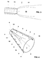
- Figure 1 shows a traditional burner. This burner has a cone shaped chamber 1 defined by two part cone shells 2 wherein air 3 is introduced through slots 4.
- the air generates in the centre of the cone shaped chamber 1 (i.e. along the axis 5 of the cone shaped chamber 1) a zone of larger vortices 6 (the vortex core).
- a lance 8 is provided along the axis 5 to inject a thin liquid fuel jet 15 into the cone shaped chamber 1; in particular the liquid fuel jet 15 is injected into the vortex core 6 to mix with the air and form a combustible mixture.
- liquid fuel jet cross section when the liquid fuel jet cross section is too small, it withstands large asymmetrical centrifugal forces since liquid fuel jet can not reliably stay within the equally small vortex core and misses the centre, with large gradients of circumferential velocity, which then prevents it from staying at the vortex core; in practice during operation the liquid fuel jet 15 fluctuates radially around the vortex core.
- Combustion instabilities can influence both the lifetime and noise emissions.
- the technical aim of the present invention is therefore to provide a burner of a gas turbine by which the said problems of the known art are eliminated or sensibly reduced.
- an aspect of the invention is to provide a burner with which combustion instabilities are limited and thus noise, in particular low frequency noise, is reduced.
- Another aspect of the invention is to provide a burner having a longer lifetime with respect to traditional burners.
- the structure of the burner is similar to that already described and, in this respect, it has two part cone shells 2 arranged offset with respect to one another and defining a cone shaped chamber 1.
- the cone shaped chamber 1 has two longitudinal tangential slots 4 for feeding air 3, and a lance 8 arranged along the axis 5 for feeding a liquid fuel.
- the burner may also have more than two part cone shells.
- the cone shells are also provided with nozzles 10 arranged on each of the cone shell, close to the tangential slots 4, to inject gaseous fuel into the cone shaped chamber 1.
- cone shells 2 are housed in a plenum (not shown) wherein compressed air coming from the compressor of the gas turbine (not shown) is fed, this air enters through the tangential slots 4 into the cone shaped chamber 1; downstream of the cone shaped chamber 1 a combustion chamber (not shown) is provided.
- the lance 8 carries a liquid fuel nozzle 12 arranged centrally in the cone shaped chamber 1, i.e. a longitudinal axis of the nozzle 12 overlaps the axis 5.
- the axis of the lance 8 is the same as the axis of the nozzle 12 and it is also the same as the axis 5 of the cone shaped chamber 1.
- the nozzle 12 has a first portion 13 with a constant diameter D and, downstream of it, a second portion 14, facing the cone shaped chamber 1, that is divergent in shape.
- the diverging portion 14 of the nozzle 12 has a diffuser angle ⁇ (i.e. an angle between the wall of the nozzle and the axis 5) of less than 5° and preferably comprised between 2-4°.
- ⁇ i.e. an angle between the wall of the nozzle and the axis 5
- the diverging portion 14 of the nozzle 12 has a diffuser length L to nozzle diameter D ratio comprised between 2-6, preferably between 3-5 and more preferably about 4, wherein the diffuser length L is the length of the diverging portion 14 of the nozzle 12 and the nozzle diameter D is the smaller diameter of the diverging portion 14 (i.e. the diameter D of the first portion 13 of the nozzle 12).
- the burner may operate with gaseous fuel and liquid fuel.
- the diameter of the liquid jet 15 is large (in particular larger than in traditional burners), when the liquid fuel jet 15 enters the vortex core 6 is subject to substantially symmetrical centrifugal forces that do not urge it outside of the vortex core 6.
- liquid jet 15 stays within the vortex core 6 without radial fluctuations, limiting in particular low frequency combustion instabilities and low frequency noise.
- the burner of the invention also lets the NO x emissions, CO emissions and smoke be sensibly reduced.
- the improved combustion stability lets and extended lifetime be achieved.
Priority Applications (4)
| Application Number | Priority Date | Filing Date | Title |
|---|---|---|---|
| EP09166907A EP2282115A1 (de) | 2009-07-30 | 2009-07-30 | Brenner einer Gasturbine |
| EP10167953.8A EP2284441A3 (de) | 2009-07-30 | 2010-06-30 | Brenner einer Gasturbine |
| AU2010202846A AU2010202846B2 (en) | 2009-07-30 | 2010-07-06 | Burner of a gas turbine |
| US12/846,087 US9435532B2 (en) | 2009-07-30 | 2010-07-29 | Burner of a gas turbine |
Applications Claiming Priority (1)
| Application Number | Priority Date | Filing Date | Title |
|---|---|---|---|
| EP09166907A EP2282115A1 (de) | 2009-07-30 | 2009-07-30 | Brenner einer Gasturbine |
Publications (1)
| Publication Number | Publication Date |
|---|---|
| EP2282115A1 true EP2282115A1 (de) | 2011-02-09 |
Family
ID=41393485
Family Applications (2)
| Application Number | Title | Priority Date | Filing Date |
|---|---|---|---|
| EP09166907A Withdrawn EP2282115A1 (de) | 2009-07-30 | 2009-07-30 | Brenner einer Gasturbine |
| EP10167953.8A Withdrawn EP2284441A3 (de) | 2009-07-30 | 2010-06-30 | Brenner einer Gasturbine |
Family Applications After (1)
| Application Number | Title | Priority Date | Filing Date |
|---|---|---|---|
| EP10167953.8A Withdrawn EP2284441A3 (de) | 2009-07-30 | 2010-06-30 | Brenner einer Gasturbine |
Country Status (3)
| Country | Link |
|---|---|
| US (1) | US9435532B2 (de) |
| EP (2) | EP2282115A1 (de) |
| AU (1) | AU2010202846B2 (de) |
Cited By (1)
| Publication number | Priority date | Publication date | Assignee | Title |
|---|---|---|---|---|
| WO2013101506A1 (en) * | 2011-12-29 | 2013-07-04 | Solar Turbines Incorporated | Method and apparatus for swaged liquid injector spoke |
Families Citing this family (3)
| Publication number | Priority date | Publication date | Assignee | Title |
|---|---|---|---|---|
| JP7044669B2 (ja) * | 2018-09-05 | 2022-03-30 | 三菱重工業株式会社 | ガスタービン燃焼器 |
| WO2020087154A1 (en) * | 2018-10-30 | 2020-05-07 | Questor Technology Inc. | Low-pressure gas burner |
| CN114508768A (zh) * | 2022-01-13 | 2022-05-17 | 南京航空航天大学 | 一种带涡控扩压器的航空燃气轮机燃烧室 |
Citations (8)
| Publication number | Priority date | Publication date | Assignee | Title |
|---|---|---|---|---|
| EP0362997A1 (de) * | 1988-08-26 | 1990-04-11 | The Dow Chemical Company | Zusammenstellung eines Brennerkopfes |
| EP0692675A2 (de) * | 1994-07-13 | 1996-01-17 | Abb Research Ltd. | Verfahren und Vorrichtung zum Betreiben eines kombinierten Brenners für flüssige und gasförmige Brennstoffe |
| DE4446609A1 (de) * | 1994-12-24 | 1996-06-27 | Abb Management Ag | Verfahren und Vorrichtung zur Brennstoffzuführung zu einem sowohl für flüssige als auch für gasförmige Brennstoffe geeigneten Brenner |
| DE19537636A1 (de) * | 1995-10-10 | 1997-04-17 | Asea Brown Boveri | Verfahren zum Betrieb einer Kraftwerksanlage |
| EP0911583A1 (de) * | 1997-10-27 | 1999-04-28 | Asea Brown Boveri AG | Verfahren zum Betrieb eines Vormischbrenners |
| WO2003054447A1 (de) * | 2001-12-20 | 2003-07-03 | Alstom Technology Ltd | Brennstofflanze |
| US20030150217A1 (en) * | 2002-02-13 | 2003-08-14 | Alstom (Switzerland) Ltd | Method for the reduction of combustion-driven oscillations in combustion systems and premixing burner for carrying out the method |
| WO2008052360A1 (en) * | 2006-11-03 | 2008-05-08 | Nxtgen Emission Controls Inc. | Fuel processor with critical flow venturi |
Family Cites Families (6)
| Publication number | Priority date | Publication date | Assignee | Title |
|---|---|---|---|---|
| US1684647A (en) * | 1927-11-28 | 1928-09-18 | Philip J Sonner | Gas burner |
| FR1226568A (fr) * | 1959-02-21 | 1960-07-13 | Siderurgie Fse Inst Rech | Brûleur à flamme stable et à forte concentration calorifique obtenue par onde de choc |
| US5431346A (en) * | 1993-07-20 | 1995-07-11 | Sinaisky; Nickoli | Nozzle including a venturi tube creating external cavitation collapse for atomization |
| JP4172270B2 (ja) * | 2000-07-05 | 2008-10-29 | オープン ストック カンパニー ケミカル オートマティック デザイン ビュロウ (シーエーディービィ) | 同軸ジェット噴射装置 |
| US6470672B1 (en) * | 2000-07-17 | 2002-10-29 | The United States Of America As Represented By The Administrator Of The National Aeronautics And Space Administration | Minimally intrusive and nonintrusive supersonic injectors for LANTR and RBCC/Scramjet propulsion systems |
| US7051956B2 (en) * | 2003-03-20 | 2006-05-30 | Sandia Naitonal Laboratories | Ejector device for direct injection fuel jet |
-
2009
- 2009-07-30 EP EP09166907A patent/EP2282115A1/de not_active Withdrawn
-
2010
- 2010-06-30 EP EP10167953.8A patent/EP2284441A3/de not_active Withdrawn
- 2010-07-06 AU AU2010202846A patent/AU2010202846B2/en not_active Ceased
- 2010-07-29 US US12/846,087 patent/US9435532B2/en not_active Expired - Fee Related
Patent Citations (9)
| Publication number | Priority date | Publication date | Assignee | Title |
|---|---|---|---|---|
| EP0362997A1 (de) * | 1988-08-26 | 1990-04-11 | The Dow Chemical Company | Zusammenstellung eines Brennerkopfes |
| EP0692675A2 (de) * | 1994-07-13 | 1996-01-17 | Abb Research Ltd. | Verfahren und Vorrichtung zum Betreiben eines kombinierten Brenners für flüssige und gasförmige Brennstoffe |
| DE4446609A1 (de) * | 1994-12-24 | 1996-06-27 | Abb Management Ag | Verfahren und Vorrichtung zur Brennstoffzuführung zu einem sowohl für flüssige als auch für gasförmige Brennstoffe geeigneten Brenner |
| DE19537636A1 (de) * | 1995-10-10 | 1997-04-17 | Asea Brown Boveri | Verfahren zum Betrieb einer Kraftwerksanlage |
| EP0911583A1 (de) * | 1997-10-27 | 1999-04-28 | Asea Brown Boveri AG | Verfahren zum Betrieb eines Vormischbrenners |
| US6270338B1 (en) | 1997-10-27 | 2001-08-07 | Asea Brown Boveri Ag | Method for operating a premix burner |
| WO2003054447A1 (de) * | 2001-12-20 | 2003-07-03 | Alstom Technology Ltd | Brennstofflanze |
| US20030150217A1 (en) * | 2002-02-13 | 2003-08-14 | Alstom (Switzerland) Ltd | Method for the reduction of combustion-driven oscillations in combustion systems and premixing burner for carrying out the method |
| WO2008052360A1 (en) * | 2006-11-03 | 2008-05-08 | Nxtgen Emission Controls Inc. | Fuel processor with critical flow venturi |
Cited By (2)
| Publication number | Priority date | Publication date | Assignee | Title |
|---|---|---|---|---|
| WO2013101506A1 (en) * | 2011-12-29 | 2013-07-04 | Solar Turbines Incorporated | Method and apparatus for swaged liquid injector spoke |
| US9296038B2 (en) | 2011-12-29 | 2016-03-29 | Solar Turbines Incorporated | Method and apparatus for swaged liquid injector spoke |
Also Published As
| Publication number | Publication date |
|---|---|
| EP2284441A2 (de) | 2011-02-16 |
| US9435532B2 (en) | 2016-09-06 |
| AU2010202846A1 (en) | 2011-02-17 |
| US20110027732A1 (en) | 2011-02-03 |
| AU2010202846B2 (en) | 2011-11-24 |
| EP2284441A3 (de) | 2014-12-17 |
Similar Documents
| Publication | Publication Date | Title |
|---|---|---|
| JP6169920B2 (ja) | 燃焼ダイナミクスを低減するためのシステムおよび方法 | |
| CN102628592B (zh) | 构造为用于减轻高频动态性的涡轮燃烧器及相关方法 | |
| JP6004976B2 (ja) | 燃焼器及びガスタービン | |
| WO2015046097A1 (ja) | ガスタービン燃焼器およびこれを備えたガスタービン機関 | |
| JP2010223577A6 (ja) | スワーラ、少なくとも1つのスワーラを備えたバーナにおける逆火の防止方法およびバーナ | |
| JP2010223577A (ja) | スワーラ、少なくとも1つのスワーラを備えたバーナにおける逆火の防止方法およびバーナ | |
| EP2650612A1 (de) | Brenner | |
| US8869533B2 (en) | Combustion system for a gas turbine comprising a resonator | |
| US20100058767A1 (en) | Swirl angle of secondary fuel nozzle for turbomachine combustor | |
| EP3076077B1 (de) | Düse, verbrennungsvorrichtung und gasturbine | |
| EP2211109A1 (de) | Brenner einer Gasturbine und Verfahren zum Mischen eines Kraftstoffs mit einem gasförmigen Strom | |
| EP2420731B1 (de) | Brenner für Nachverbrennung | |
| EP2282115A1 (de) | Brenner einer Gasturbine | |
| WO2016193068A1 (en) | Combustor arrangement | |
| US6978619B2 (en) | Premixed burner with profiled air mass stream, gas turbine and process for burning fuel in air | |
| US7827777B2 (en) | Combustor with reduced carbon monoxide emissions | |
| EP2685163B1 (de) | Multikonus-Vormischungsbrenner für eine Gasturbine | |
| JP4776697B2 (ja) | ガスタービン用燃焼器およびガスタービン用燃焼器の運転方法 | |
| EP3325886B1 (de) | Vorrichtung mit anordnung aus brennstoffdüsen zur abschwächung der verbrennungsdynamik bei einem gasturbinenmotor | |
| US20100192591A1 (en) | Burner for a gas turbine and method for feeding a gaseous fuel in a burner | |
| EP2420730B1 (de) | Nachbrenner | |
| US8966905B2 (en) | Combustion device | |
| CN108954386B (zh) | 混合器及用于操作该混合器的方法 | |
| JP2017048978A (ja) | ガスタービン燃焼器、ガスタービン、及びガスタービン燃焼器のバーナ |
Legal Events
| Date | Code | Title | Description |
|---|---|---|---|
| PUAI | Public reference made under article 153(3) epc to a published international application that has entered the european phase |
Free format text: ORIGINAL CODE: 0009012 |
|
| AK | Designated contracting states |
Kind code of ref document: A1 Designated state(s): AT BE BG CH CY CZ DE DK EE ES FI FR GB GR HR HU IE IS IT LI LT LU LV MC MK MT NL NO PL PT RO SE SI SK SM TR |
|
| AX | Request for extension of the european patent |
Extension state: AL BA RS |
|
| STAA | Information on the status of an ep patent application or granted ep patent |
Free format text: STATUS: THE APPLICATION IS DEEMED TO BE WITHDRAWN |
|
| 18D | Application deemed to be withdrawn |
Effective date: 20110810 |