EP2282107A2 - Vehicle lamp - Google Patents
Vehicle lamp Download PDFInfo
- Publication number
- EP2282107A2 EP2282107A2 EP10171903A EP10171903A EP2282107A2 EP 2282107 A2 EP2282107 A2 EP 2282107A2 EP 10171903 A EP10171903 A EP 10171903A EP 10171903 A EP10171903 A EP 10171903A EP 2282107 A2 EP2282107 A2 EP 2282107A2
- Authority
- EP
- European Patent Office
- Prior art keywords
- light emitting
- emitting device
- semiconductor light
- supply module
- power supply
- Prior art date
- Legal status (The legal status is an assumption and is not a legal conclusion. Google has not performed a legal analysis and makes no representation as to the accuracy of the status listed.)
- Withdrawn
Links
- 239000004065 semiconductor Substances 0.000 claims abstract description 34
- 230000003287 optical effect Effects 0.000 claims abstract description 25
- 238000003780 insertion Methods 0.000 description 6
- 230000037431 insertion Effects 0.000 description 6
- 239000000463 material Substances 0.000 description 2
- XAGFODPZIPBFFR-UHFFFAOYSA-N aluminium Chemical compound [Al] XAGFODPZIPBFFR-UHFFFAOYSA-N 0.000 description 1
- 229910052782 aluminium Inorganic materials 0.000 description 1
- 239000004020 conductor Substances 0.000 description 1
- 238000002788 crimping Methods 0.000 description 1
- 238000010348 incorporation Methods 0.000 description 1
- 238000012986 modification Methods 0.000 description 1
- 230000004048 modification Effects 0.000 description 1
- 239000000843 powder Substances 0.000 description 1
- 239000011347 resin Substances 0.000 description 1
- 229920005989 resin Polymers 0.000 description 1
- 238000005476 soldering Methods 0.000 description 1
- 229910001220 stainless steel Inorganic materials 0.000 description 1
- 239000010935 stainless steel Substances 0.000 description 1
- 238000003466 welding Methods 0.000 description 1
Images


Classifications
-
- F—MECHANICAL ENGINEERING; LIGHTING; HEATING; WEAPONS; BLASTING
- F21—LIGHTING
- F21V—FUNCTIONAL FEATURES OR DETAILS OF LIGHTING DEVICES OR SYSTEMS THEREOF; STRUCTURAL COMBINATIONS OF LIGHTING DEVICES WITH OTHER ARTICLES, NOT OTHERWISE PROVIDED FOR
- F21V23/00—Arrangement of electric circuit elements in or on lighting devices
-
- F—MECHANICAL ENGINEERING; LIGHTING; HEATING; WEAPONS; BLASTING
- F21—LIGHTING
- F21S—NON-PORTABLE LIGHTING DEVICES; SYSTEMS THEREOF; VEHICLE LIGHTING DEVICES SPECIALLY ADAPTED FOR VEHICLE EXTERIORS
- F21S41/00—Illuminating devices specially adapted for vehicle exteriors, e.g. headlamps
- F21S41/10—Illuminating devices specially adapted for vehicle exteriors, e.g. headlamps characterised by the light source
- F21S41/14—Illuminating devices specially adapted for vehicle exteriors, e.g. headlamps characterised by the light source characterised by the type of light source
- F21S41/141—Light emitting diodes [LED]
- F21S41/151—Light emitting diodes [LED] arranged in one or more lines
-
- F—MECHANICAL ENGINEERING; LIGHTING; HEATING; WEAPONS; BLASTING
- F21—LIGHTING
- F21S—NON-PORTABLE LIGHTING DEVICES; SYSTEMS THEREOF; VEHICLE LIGHTING DEVICES SPECIALLY ADAPTED FOR VEHICLE EXTERIORS
- F21S41/00—Illuminating devices specially adapted for vehicle exteriors, e.g. headlamps
- F21S41/10—Illuminating devices specially adapted for vehicle exteriors, e.g. headlamps characterised by the light source
- F21S41/19—Attachment of light sources or lamp holders
- F21S41/192—Details of lamp holders, terminals or connectors
-
- F—MECHANICAL ENGINEERING; LIGHTING; HEATING; WEAPONS; BLASTING
- F21—LIGHTING
- F21S—NON-PORTABLE LIGHTING DEVICES; SYSTEMS THEREOF; VEHICLE LIGHTING DEVICES SPECIALLY ADAPTED FOR VEHICLE EXTERIORS
- F21S43/00—Signalling devices specially adapted for vehicle exteriors, e.g. brake lamps, direction indicator lights or reversing lights
- F21S43/10—Signalling devices specially adapted for vehicle exteriors, e.g. brake lamps, direction indicator lights or reversing lights characterised by the light source
- F21S43/13—Signalling devices specially adapted for vehicle exteriors, e.g. brake lamps, direction indicator lights or reversing lights characterised by the light source characterised by the type of light source
- F21S43/14—Light emitting diodes [LED]
-
- F—MECHANICAL ENGINEERING; LIGHTING; HEATING; WEAPONS; BLASTING
- F21—LIGHTING
- F21S—NON-PORTABLE LIGHTING DEVICES; SYSTEMS THEREOF; VEHICLE LIGHTING DEVICES SPECIALLY ADAPTED FOR VEHICLE EXTERIORS
- F21S43/00—Signalling devices specially adapted for vehicle exteriors, e.g. brake lamps, direction indicator lights or reversing lights
- F21S43/10—Signalling devices specially adapted for vehicle exteriors, e.g. brake lamps, direction indicator lights or reversing lights characterised by the light source
- F21S43/19—Attachment of light sources or lamp holders
- F21S43/195—Details of lamp holders, terminals or connectors
Definitions
- a semiconductor light emitting device such as a light emitting diode, emits light with very small current. Accordingly, a semiconductor light emitting device has low power consumption and long life as compared to a filament bulb.
- Related art vehicle lamps include, for example, a vehicle tail lamp having a semiconductor light emitting device as a light source (see, e.g., JP 2008-084578 A ) and a vehicle headlamp having a high-luminance semiconductor light emitting device.
- a vehicle lamp includes a semiconductor light emitting device as a light source, a power supply module configured to supply electric power from a power source to the semiconductor light emitting device, and a housing in which the power supply module is accommodated.
- the semiconductor light emitting device is mounted on the power supply module.
- the power supply module comprises a current control circuit configured to control an amount of current supplied to the semiconductor light emitting device.
- the semiconductor light emitting device and the current control circuit are arranged to overlap each other in a direction of an optical axis of the semiconductor light emitting device. Therefore, a vehicle lamp according to the present invention notably enables the incorporation of the current control circuit in the power supply module in a space-saving manner without increasing the size of the housing in directions perpendicular to the optical axis of the semiconductor light emitting device.
- Figs. 1 to 4 illustrate aspects of a vehicle lamp according to the exemplary embodiment.
- the vehicle lamp includes a power supply module 100, a light emitting device 120 mounted on the power supply module 100 to serve as a light source of the vehicle lamp, and a housing 200 configured to accommodate the power supply module 100 and the light emitting device 120.
- the vehicle lamp is adapted for use in, for example, a rear combination lamp, or in a headlamp to irradiate a region in front of a vehicle.
- insertion holes 113 are formed at five positions, that is, four positions on the conductive plate 110a and one position on the conductive plate 110f. Further, an insertion hole 133, which is larger than the insertion hole 113, is formed at another position on the conductive plate 110f.
- Each of the conductive plates 110a, 110c, 110e, 110f are bent along the respective broken lines shown in Fig. 2 , whereby the power supply module 100 as shown in Fig. 1 is formed.
- Each of the side walls 114a, 114b, 114c, 114d has an extension wall 115a, 115b, 115c, 115d, which extend in a direction substantially perpendicular to the direction of the optical axis of the light emitting device 120. Further, according to this exemplary embodiment, the extension walls 115a, 115b, 115c, 115d are further folded toward the optical axis of the light emitting device 120 at corner portions between the adjacent ones the side walls 114a, 114b, 114c, 114d.
- the housing 200 includes an upper housing part 220 and a lower housing part 210.
- the lower housing part 210 includes a disk-shaped bottom wall 212 and a cylindrical side wall 211 that extends from the bottom wall 212 so as to be perpendicular to the bottom wall.
- a connector 216 extends from a center region of the bottom wall 212 in a direction opposite to the direction in which the side wall 211 extends.
- a plurality of stepped bosses 213 (five in this exemplary embodiment) is disposed in a region surrounded by the side wall 211.
- Each of the stepped bosses 213 is provided to extend from the bottom wall 212 substantially in the same direction as the side wall 211 in a columnar manner.
- An upper portion of each of the stepped bosses 213 has a diameter substantially equal to an inner diameter of the insertion hole 113 of the power supply module 100.
- locking protrusions 215 are provided on the side wall 211 of the lower housing part 210 at regular intervals along a circumferential direction of the side wall 211.
- three locking protrusions 215 are arranged at intervals of 120°. The locking protrusions 215 are used when attaching the vehicle lamp to a lamp body 300.
- the upper housing part 220 includes a top wall 222 having an opening 224 in a center thereof, and a cylindrical side wall 221 extending from the top wall 222 substantially perpendicular to the top wall 222.
- the top wall 222 has a curved surface, which is concave in the direction in which the side wall 221 extends, on an opposite side of the side wall 221.
- a material having high reflectance such as aluminum, is deposited.
- the vehicle lamp is assembled by attaching the power supply module 100 to the lower housing part 210 so that the light emitting device 120 faces upward, and fitting the upper housing part 220 to the lower housing part 210. More specifically, first, the stepped bosses 213 of the lower housing part 210 are inserted into the insertion holes 113 of the power supply module 100. Then, portions of the respective stepped bosses 213, which protrude from the insertion holes 113, are welded, whereby the power supply module 100 is fixed to the lower housing part 210.
- extension walls 115a, 115b, 115c, 115d are folded toward the optical axis of the light emitting device 120. Therefore, it is possible to provide the extension walls 115a, 115b, 115c, 115d without increasing the size of the housing 200 in directions perpendicular to the optical axis of the light emitting device 120.
- the light source attaching portion 310 is a cylindrical portion extending from an opening 320 in the lamp body 300.
- An inner diameter of the light source attaching portion 310 is substantially equal to an outer diameter of the lower housing part 210.
- Engaging grooves 311 are formed in the light source attaching portion 310 at regular intervals along the circumferential direction. In this exemplary embodiment, three engaging grooves 311 are arranged at intervals of 120°.
Landscapes
- Engineering & Computer Science (AREA)
- General Engineering & Computer Science (AREA)
- Physics & Mathematics (AREA)
- Microelectronics & Electronic Packaging (AREA)
- Optics & Photonics (AREA)
- Non-Portable Lighting Devices Or Systems Thereof (AREA)
- Lighting Device Outwards From Vehicle And Optical Signal (AREA)
Abstract
A vehicle lamp includes a semiconductor light emitting device (120) as light source, a power supply module (100) configured to supply electric power from a power source to the semiconductor light emitting device (120), and a housing (200) in which the power supply module (100) is accommodated. The semiconductor light emitting device (120) is mounted on the power supply module (100). The power supply module (100) comprises a current control circuit (110b-110e, 116, 117) configured to control an amount of current supplied to the semiconductor light emitting device (120). The semiconductor light emitting device (120) and the current control circuit (110b-110e, 116, 117) are arranged to overlap each other in a direction of an optical axis of the semiconductor light emitting device (120).
Description
- Apparatuses consistent with the present invention relate to a vehicle lamp and, more particularly, to a vehicle lamp having a semiconductor light emitting device which serves as a light source, a power supply module configured to supply electric power from a power source to the semiconductor light emitting device, and a housing configured to accommodate the power supply module.
- A semiconductor light emitting device, such as a light emitting diode, emits light with very small current. Accordingly, a semiconductor light emitting device has low power consumption and long life as compared to a filament bulb. Related art vehicle lamps include, for example, a vehicle tail lamp having a semiconductor light emitting device as a light source (see, e.g.,
JP 2008-084578 A - When using a semiconductor light emitting device as a light source of a vehicle lamp, a current control circuit is provided to control current supplied to the semiconductor light emitting device. The current control circuit is arranged in a limited space inside a lamp housing. Further, a semiconductor light emitting device is relatively weak against heat. Therefore, a heat dissipating structure is provided to efficiently dissipate heat from the semiconductor light emitting device and the current control circuit.
- According to an illustrative aspect of the present invention, a vehicle lamp includes a semiconductor light emitting device as a light source, a power supply module configured to supply electric power from a power source to the semiconductor light emitting device, and a housing in which the power supply module is accommodated. The semiconductor light emitting device is mounted on the power supply module. The power supply module comprises a current control circuit configured to control an amount of current supplied to the semiconductor light emitting device. The semiconductor light emitting device and the current control circuit are arranged to overlap each other in a direction of an optical axis of the semiconductor light emitting device.
Therefore, a vehicle lamp according to the present invention notably enables the incorporation of the current control circuit in the power supply module in a space-saving manner without increasing the size of the housing in directions perpendicular to the optical axis of the semiconductor light emitting device. - Other aspects and advantages of the invention will be apparent from the following description, the drawings and the claims.
-
-
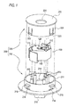
Fig. 1 is an exploded perspective view of a vehicle lamp according to an exemplary embodiment of the present invention; -
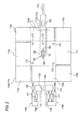
Fig. 2 is a plan view of a power supply module before being formed as a casing; -
Fig. 3 is a top view of the power supply module mounted on a lower housing part; -
Fig. 4 is a sectional view of the vehicle lamp; and -
Fig. 5 is an enlarged view of a light source attaching portion of a lamp body. - Hereinafter, an exemplary embodiment of the present invention will be described in detail with reference to the drawings. However, the following exemplary embodiment does not limit the scope of the claimed invention.
-
Figs. 1 to 4 illustrate aspects of a vehicle lamp according to the exemplary embodiment. As shown inFig. 1 , the vehicle lamp includes apower supply module 100, alight emitting device 120 mounted on thepower supply module 100 to serve as a light source of the vehicle lamp, and ahousing 200 configured to accommodate thepower supply module 100 and thelight emitting device 120. The vehicle lamp is adapted for use in, for example, a rear combination lamp, or in a headlamp to irradiate a region in front of a vehicle. - As shown in
Fig. 1 , thepower supply module 100 has a form of a casing like a rectangular box. Thepower supply module 100 has aconductive plate 110 which forms an exterior of thepower supply module 100. As shown inFig. 2 , thepower supply module 100 may be manufactured by providing planar members and three-dimensionally assembling the planar members. More specifically, according to the exemplary embodiment, a plurality ofconductive plates - Then, the
conductive plates rectifier diodes 116, andcurrent control resistors 117 are fixed to one side of theconductive plate 110a as shown inFig. 2 . Therectifier diodes 116 and thecurrent control resistors 117 may be fixed to theconductive plates rectifier diodes 116 and thecurrent control resistors 117 are fixed to theconductive plates conductive plates - The
light emitting device 120 is fixed to theconductive plate 110a at a position shown inFig. 2 such that the optical axis of thelight emitting device 120 is directed toward the front of the lamp. Thelight emitting device 120 is an example of a semiconductor light emitting device, and includes alight emitting part 122 and alead frame 123 as shown inFig. 2 . Thelight emitting part 122 may have a plurality of LED chips 121 (three in this exemplary embodiment). TheLED chips 121 are sealed by a transparent resin material, and are electrically coupled to each other via thelead frame 123. Both ends of thelead frame 123 extend out from respective sides of thelight emitting part 122. - One of the extended portions of the
lead frame 123 serves as a positive terminal of thelight emitting device 120, and is fixed to theconductive plate 110a and electrically coupled to theconductive plate 110a. The other of the extending portions serves as a ground terminal of thelight emitting device 120, and is fixed to theconductive plate 110f and electrically coupled to theconductive plate 110f. Thelead frame 123 is fixed to theconductive plates - The
conductive plate 110a is configured to function as a positiveelectrode connecting part 111, and is electrically coupled to a positive electrode of a power source via a current control circuit and power source-side electrodes conductive plate 110f is configured to function as aground connecting part 112, and is electrically coupled to a ground potential via a ground-side electrode 118c. - After the
light emitting device 120 is mounted as described above, as shown inFig. 2 ,insertion holes 113 are formed at five positions, that is, four positions on theconductive plate 110a and one position on theconductive plate 110f. Further, aninsertion hole 133, which is larger than theinsertion hole 113, is formed at another position on theconductive plate 110f. Each of theconductive plates Fig. 2 , whereby thepower supply module 100 as shown inFig. 1 is formed. - Portions along and near a perimeter of the positive electrode connecting part 111 (the
conductive plate 110a) are folded so as to be substantially parallel to the direction of the optical axis of thelight emitting device 120, respectively, thereby formingside walls power supply module 100. A portion of the ground connecting part 112 (theconductive plate 110f) is also folded so as to be substantially parallel to the direction of the optical axis of thelight emitting device 120, thereby forming a part of theside wall 114d. - Each of the
side walls extension wall light emitting device 120. Further, according to this exemplary embodiment, theextension walls light emitting device 120 at corner portions between the adjacent ones theside walls - Distal end portions of the
conductive plates light emitting device 120, thereby formingelectrodes connector 216 when thepower supply module 100 is fitted to the housing 200 (seeFig. 4 ). In this exemplary embodiment, theelectrodes conductive plates electrode 118c formed by folding the distal end portion of theconductive plate 110f functions as a ground-side electrode that is coupled to ground potential. - The
light emitting device 120 is mounted at a center of a top surface of thepower supply module 100. On the other hand, theconductive plates rectifier diodes 116, and thecurrent control resistors 117 are arranged in a bottom side of thepower supply module 100. Theconductive plates rectifier diodes 116, and thecurrent control resistors 117 form a current control circuit that controls an amount of current supplied from the power source-side electrodes light emitting device 120. - The
housing 200 includes anupper housing part 220 and alower housing part 210. Thelower housing part 210 includes a disk-shaped bottom wall 212 and acylindrical side wall 211 that extends from thebottom wall 212 so as to be perpendicular to the bottom wall. Aconnector 216 extends from a center region of thebottom wall 212 in a direction opposite to the direction in which theside wall 211 extends. Further, a plurality of stepped bosses 213 (five in this exemplary embodiment) is disposed in a region surrounded by theside wall 211. Each of thestepped bosses 213 is provided to extend from thebottom wall 212 substantially in the same direction as theside wall 211 in a columnar manner. An upper portion of each of thestepped bosses 213 has a diameter substantially equal to an inner diameter of theinsertion hole 113 of thepower supply module 100. - As shown in
Figs. 1 and3 ,locking protrusions 215 are provided on theside wall 211 of thelower housing part 210 at regular intervals along a circumferential direction of theside wall 211. In the exemplary embodiment, three lockingprotrusions 215 are arranged at intervals of 120°. The lockingprotrusions 215 are used when attaching the vehicle lamp to alamp body 300. - The
upper housing part 220 includes atop wall 222 having anopening 224 in a center thereof, and acylindrical side wall 221 extending from thetop wall 222 substantially perpendicular to thetop wall 222. Thetop wall 222 has a curved surface, which is concave in the direction in which theside wall 221 extends, on an opposite side of theside wall 221. On the curved surface of thetop wall 222, a material having high reflectance, such as aluminum, is deposited. - Fitting
protrusions 223 are formed on theside wall 221 of theupper housing part 220 at regular intervals along the circumferential direction. In this exemplary embodiment, threefitting protrusions 223 are arranged at intervals of 120°. Counterpartfitting holes 214 are formed in theside wall 211 of thelower housing part 210 at regular intervals along the circumferential direction. In this exemplary embodiment, threefitting holes 214 are arranged at intervals of 120°. - The vehicle lamp is assembled by attaching the
power supply module 100 to thelower housing part 210 so that thelight emitting device 120 faces upward, and fitting theupper housing part 220 to thelower housing part 210. More specifically, first, the steppedbosses 213 of thelower housing part 210 are inserted into the insertion holes 113 of thepower supply module 100. Then, portions of the respective steppedbosses 213, which protrude from the insertion holes 113, are welded, whereby thepower supply module 100 is fixed to thelower housing part 210. - The
extension walls side walls power supply module 100, are folded toward the optical axis of thelight emitting device 120 as described above. Therefore, when thepowder supply module 100 is fitted to thelower housing part 210, theextension walls Fig. 3 . - Next, the
upper housing part 220 and is fitted to thelower housing part 210. More specifically, an outer surface of theside wall 221 of theupper housing part 220 slides on an inner surface of theside wall 211 of thelower housing part 210, and thefitting protrusions 223 of theupper housing part 220 are fitted into the respectivefitting holes 214 of thelower housing part 210, so that the upper andlower housing parts - According to the vehicle lamp assembled in the manner described above, as shown in
Fig. 4 , the light emitting surface of thelight emitting device 120 is exposed to the outside through theopening 224 of theupper housing part 220. The direction of the optical axis of thelight emitting device 120 is oriented in a front-rear direction of the lamp (the vertical direction inFig. 4 ). Theelectrodes power supply module 100 protrude from a central portion of theconnector 216 along the direction of the optical axis of thelight emitting device 120. - The
power supply module 100 is configured such that thelight emitting device 120 and the current control circuit are arranged to overlap each other in the direction of the optical axis of thelight emitting device 120. Therefore, the current control circuit can be incorporated in thepower supply module 100 in a space-saving manner without increasing a size of thehousing 200 in directions perpendicular to the optical axis of thelight emitting device 120. - Further, a portion of the positive
electrode connecting part 111 and a portion theground connecting part 112 are folded so as to be substantially parallel to the optical axis. Therefore, an area occupied by the positiveelectrode connecting part 111 and theground connecting part 112 can be reduced in directions perpendicular to the optical axis of thelight emitting device 120. According to another exemplary embodiment, thepower supply module 100 may be configured such that a portion of one of the positiveelectrode connecting part 111 and theground connecting part 112 is folded so as to be substantially parallel to the optical axis. In this case, likewise, an area occupied by the positiveelectrode connecting part 111 or theground connecting part 112 can be reduced in directions perpendicular to the optical axis of thelight emitting device 120. - The
extension walls electrode connecting part 111 and theground connecting part 112, and are configured and arranged to function as heat dissipating fins (heat sinks). Therefore, separate heat dissipating fins need not be provided in addition to thepower supply module 100. - Further, the
extension walls light emitting device 120. Therefore, it is possible to provide theextension walls housing 200 in directions perpendicular to the optical axis of thelight emitting device 120. -
Fig. 5 is an enlarged view of a lightsource attaching portion 310 of thelamp body 300 to which the vehicle lamp is attached. Thelamp body 300 is, for example a portion of a headlamp. - The light
source attaching portion 310 is a cylindrical portion extending from anopening 320 in thelamp body 300. An inner diameter of the lightsource attaching portion 310 is substantially equal to an outer diameter of thelower housing part 210. Engaginggrooves 311 are formed in the lightsource attaching portion 310 at regular intervals along the circumferential direction. In this exemplary embodiment, three engaginggrooves 311 are arranged at intervals of 120°. - When attaching the vehicle lamp to the
lamp body 300, first, the lockingprotrusions 215 of the vehicle lamp are inserted into the respectiveengaging grooves 311 of the lightsource attaching portion 310. Then, the vehicle lamp is rotated so that the lockingprotrusions 215 are guided by the engaginggrooves 311 and are fitted to lockingrecesses 312 that are formed at the ends of the respectiveengaging grooves 311, whereby the vehicle lamp is fixed to thelamp body 300. - While the present invention has been described with reference to a certain exemplary embodiment thereof, the scope of the present invention is not limited to the exemplary embodiment described above, and it will be understood by those skilled in the art that various changes and modifications may be made therein without departing from the scope of the present invention as defined by the appended claims.
Claims (6)
- A vehicle lamp characterized by comprising:a semiconductor light emitting device (120) configured to serve as a light source of the vehicle lamp;a power supply module (100) configured to supply electric power from a power source to the semiconductor light emitting device (120); anda housing (200) in which the power supply module (100) is accommodated,wherein the semiconductor light emitting device (120) is mounted on the power supply module (100),the power supply module (100) comprises a current control circuit (110b-110e, 116, 117) configured to control an amount of current supplied to the semiconductor light emitting device (120), andthe semiconductor light emitting device (120) and the current control circuit (110b-110e, 116, 117) are arranged to overlap each other in a direction of an optical axis of the semiconductor light emitting device (120).
- The vehicle lamp according to claim 1, wherein the semiconductor light emitting device (120) comprises a positive terminal and a ground terminal, and
the power supply module (100) further comprises:a positive electrode connecting part (110a, 111) configured to electrically couple the positive terminal of the semiconductor light emitting device (120) and a positive electrode of the power source; anda ground connecting part (110f, 112) configured to electrically couple the ground terminal of the semiconductor light emitting device (120) and a ground potential,wherein at least one of the positive electrode connecting part (110a, 111) and the ground connecting part (110f, 112) comprises a folded portion (114a-114d) that is folded so as to extend in the direction of the optical axis. - The vehicle lamp according to claim 2, wherein the at least one of the positive electrode connecting part (110a, 111) and the ground connecting part (110f, 112) further comprises an extension wall (115a-115d) extending from the folded portion (114a-114d) in a direction substantially perpendicular to the direction of the optical axis.
- The vehicle lamp according to claim 3, wherein the extension wall (115a-115d) is folded toward the optical axis.
- The vehicle lamp according to any one of the preceding claims, wherein the housing (200) comprises:a first housing part (210) to which the power supply module (100) is attached; anda second housing part (220) comprising an opening (224),wherein the second housing part (220) is attached to the first housing part (210) such that the optical axis of the semiconductor light emitting device (120) extends through the opening (224).
- The vehicle lamp according to claim 5, wherein the current control circuit (110b-110e, 116, 117) comprises an electrode (118a, 118b) configured to be electrically coupled to the power source, and
the first housing part (210) comprises a connector (216) into which the electrode (118a, 118b) of the current control circuit (110b-110e, 116, 117) extends.
Applications Claiming Priority (1)
| Application Number | Priority Date | Filing Date | Title |
|---|---|---|---|
| JP2009184288A JP5451243B2 (en) | 2009-08-07 | 2009-08-07 | Vehicle lighting |
Publications (1)
| Publication Number | Publication Date |
|---|---|
| EP2282107A2 true EP2282107A2 (en) | 2011-02-09 |
Family
ID=43097621
Family Applications (1)
| Application Number | Title | Priority Date | Filing Date |
|---|---|---|---|
| EP10171903A Withdrawn EP2282107A2 (en) | 2009-08-07 | 2010-08-04 | Vehicle lamp |
Country Status (5)
| Country | Link |
|---|---|
| US (1) | US8264152B2 (en) |
| EP (1) | EP2282107A2 (en) |
| JP (1) | JP5451243B2 (en) |
| KR (1) | KR101201607B1 (en) |
| CN (1) | CN101994970B (en) |
Families Citing this family (2)
| Publication number | Priority date | Publication date | Assignee | Title |
|---|---|---|---|---|
| CN103256541A (en) * | 2012-02-15 | 2013-08-21 | 宁波比格斯通光电科技有限公司 | Vehicle lamp with integrated far and near light |
| CN103953886B (en) * | 2014-04-30 | 2016-02-10 | 常州星宇车灯股份有限公司 | The dimming components of front fog lamp of automobile and heat shield combination assembling device |
Citations (1)
| Publication number | Priority date | Publication date | Assignee | Title |
|---|---|---|---|---|
| JP2008084578A (en) | 2006-09-26 | 2008-04-10 | Koito Mfg Co Ltd | Vehicle lighting |
Family Cites Families (12)
| Publication number | Priority date | Publication date | Assignee | Title |
|---|---|---|---|---|
| JPH0481305U (en) * | 1990-11-22 | 1992-07-15 | ||
| JPH11273423A (en) * | 1998-03-19 | 1999-10-08 | Elna Co Ltd | Light-emitting diode assembly lamp |
| JP4246333B2 (en) * | 1999-10-29 | 2009-04-02 | 富士重工業株式会社 | Vehicle lamp |
| JP2003152228A (en) * | 2001-11-12 | 2003-05-23 | Sumitomo Bakelite Co Ltd | LED case and LED light emitter |
| JP2004319121A (en) * | 2003-04-11 | 2004-11-11 | Stanley Electric Co Ltd | LED lamp socket |
| JP2005183531A (en) * | 2003-12-17 | 2005-07-07 | Sharp Corp | Semiconductor light emitting device |
| JP2005322528A (en) * | 2004-05-10 | 2005-11-17 | Ichikoh Ind Ltd | Vehicle lighting |
| JP2006202864A (en) * | 2005-01-19 | 2006-08-03 | Souji Kobayashi | LED bulb |
| JP4345017B2 (en) * | 2005-04-28 | 2009-10-14 | 住友電装株式会社 | Light emitting device |
| JP2008166412A (en) * | 2006-12-27 | 2008-07-17 | Koito Mfg Co Ltd | Light emitting element drive circuit and vehicle lamp |
| CN101368714A (en) * | 2007-08-16 | 2009-02-18 | 大亿交通工业制造股份有限公司 | Heat radiating device for LED vehicle lamp |
| US7841756B2 (en) * | 2008-01-31 | 2010-11-30 | Honda Motor Co., Ltd. | Vehicle lamp assembly |
-
2009
- 2009-08-07 JP JP2009184288A patent/JP5451243B2/en not_active Expired - Fee Related
-
2010
- 2010-07-26 US US12/843,193 patent/US8264152B2/en not_active Expired - Fee Related
- 2010-08-04 EP EP10171903A patent/EP2282107A2/en not_active Withdrawn
- 2010-08-05 KR KR1020100075563A patent/KR101201607B1/en not_active Expired - Fee Related
- 2010-08-06 CN CN2010102503929A patent/CN101994970B/en not_active Expired - Fee Related
Patent Citations (1)
| Publication number | Priority date | Publication date | Assignee | Title |
|---|---|---|---|---|
| JP2008084578A (en) | 2006-09-26 | 2008-04-10 | Koito Mfg Co Ltd | Vehicle lighting |
Also Published As
| Publication number | Publication date |
|---|---|
| JP5451243B2 (en) | 2014-03-26 |
| CN101994970A (en) | 2011-03-30 |
| KR20110015389A (en) | 2011-02-15 |
| US8264152B2 (en) | 2012-09-11 |
| US20110031884A1 (en) | 2011-02-10 |
| JP2011040188A (en) | 2011-02-24 |
| CN101994970B (en) | 2012-10-10 |
| KR101201607B1 (en) | 2012-11-14 |
Similar Documents
| Publication | Publication Date | Title |
|---|---|---|
| US8444308B2 (en) | Vehicular lamp | |
| US9644809B2 (en) | Light source unit | |
| EP2228587B1 (en) | Led bulb and lighting apparatus | |
| JP4962253B2 (en) | LED bulb | |
| JP5779329B2 (en) | Vehicle lighting | |
| EP1914470B1 (en) | Semiconductor lamp | |
| US10203080B1 (en) | Lighting device for vehicles and lighting tool for vehicles | |
| WO2011052639A1 (en) | Led lighting device | |
| EP2873909B1 (en) | Light emitting diode bulb | |
| KR101295281B1 (en) | Lighting apparatus | |
| JP2015220034A (en) | Led module and vehicle lamp fitting including the same | |
| JP2015220035A (en) | Led module and vehicle lamp fitting including the same | |
| JP2018092847A (en) | Light source unit | |
| JP5582899B2 (en) | Lamp and lighting device | |
| US8264152B2 (en) | Vehicle lamp | |
| US9979154B2 (en) | Semiconductor laser device | |
| JP6136014B2 (en) | Lighting device | |
| JP6712769B2 (en) | Light source unit, lighting device, and vehicle | |
| JP6108304B2 (en) | Illumination light source and illumination device | |
| TW201339485A (en) | Lamp | |
| WO2013128733A1 (en) | Light-emitting device, and illumination apparatus using same | |
| US20170067626A1 (en) | Light source module | |
| JP2015065034A (en) | Vehicle lamp using a light source module | |
| JP7056433B2 (en) | Vehicle lighting equipment and vehicle lighting equipment | |
| CN106287452A (en) | LED light device and ligthing paraphernalia |
Legal Events
| Date | Code | Title | Description |
|---|---|---|---|
| PUAI | Public reference made under article 153(3) epc to a published international application that has entered the european phase |
Free format text: ORIGINAL CODE: 0009012 |
|
| 17P | Request for examination filed |
Effective date: 20100804 |
|
| AK | Designated contracting states |
Kind code of ref document: A2 Designated state(s): AL AT BE BG CH CY CZ DE DK EE ES FI FR GB GR HR HU IE IS IT LI LT LU LV MC MK MT NL NO PL PT RO SE SI SK SM TR |
|
| AX | Request for extension of the european patent |
Extension state: BA ME RS |
|
| STAA | Information on the status of an ep patent application or granted ep patent |
Free format text: STATUS: THE APPLICATION HAS BEEN WITHDRAWN |
|
| 18W | Application withdrawn |
Effective date: 20160609 |