EP2282071B1 - Spline telescopic shaft and method of manufacturing - Google Patents
Spline telescopic shaft and method of manufacturing Download PDFInfo
- Publication number
- EP2282071B1 EP2282071B1 EP10171834.4A EP10171834A EP2282071B1 EP 2282071 B1 EP2282071 B1 EP 2282071B1 EP 10171834 A EP10171834 A EP 10171834A EP 2282071 B1 EP2282071 B1 EP 2282071B1
- Authority
- EP
- European Patent Office
- Prior art keywords
- shaft
- spline
- resin coating
- manufacturing
- intermediate member
- Prior art date
- Legal status (The legal status is an assumption and is not a legal conclusion. Google has not performed a legal analysis and makes no representation as to the accuracy of the status listed.)
- Active
Links
- 238000004519 manufacturing process Methods 0.000 title claims description 86
- 229920005989 resin Polymers 0.000 claims description 140
- 239000011347 resin Substances 0.000 claims description 140
- 238000000576 coating method Methods 0.000 claims description 98
- 239000011248 coating agent Substances 0.000 claims description 94
- 238000000034 method Methods 0.000 claims description 67
- 230000008569 process Effects 0.000 claims description 51
- 239000010410 layer Substances 0.000 claims description 28
- 238000005299 abrasion Methods 0.000 claims description 13
- 238000010438 heat treatment Methods 0.000 claims description 11
- 238000002844 melting Methods 0.000 claims description 9
- 230000008018 melting Effects 0.000 claims description 9
- 239000002344 surface layer Substances 0.000 claims description 5
- 239000000843 powder Substances 0.000 claims description 4
- 230000003746 surface roughness Effects 0.000 description 12
- 230000000052 comparative effect Effects 0.000 description 9
- 239000000463 material Substances 0.000 description 5
- 230000003068 static effect Effects 0.000 description 5
- 230000005540 biological transmission Effects 0.000 description 4
- 238000005520 cutting process Methods 0.000 description 4
- 230000000694 effects Effects 0.000 description 4
- 239000004519 grease Substances 0.000 description 4
- 230000007246 mechanism Effects 0.000 description 4
- 238000007781 pre-processing Methods 0.000 description 4
- 239000004952 Polyamide Substances 0.000 description 2
- 230000002159 abnormal effect Effects 0.000 description 2
- 230000003247 decreasing effect Effects 0.000 description 2
- 238000010586 diagram Methods 0.000 description 2
- 230000020169 heat generation Effects 0.000 description 2
- 239000000314 lubricant Substances 0.000 description 2
- 230000002093 peripheral effect Effects 0.000 description 2
- 229920002647 polyamide Polymers 0.000 description 2
- 230000009467 reduction Effects 0.000 description 2
- 229930182556 Polyacetal Natural products 0.000 description 1
- 229910009372 YVO4 Inorganic materials 0.000 description 1
- 238000010521 absorption reaction Methods 0.000 description 1
- 238000005422 blasting Methods 0.000 description 1
- 239000002775 capsule Substances 0.000 description 1
- 238000005266 casting Methods 0.000 description 1
- 238000010273 cold forging Methods 0.000 description 1
- 230000008878 coupling Effects 0.000 description 1
- 238000010168 coupling process Methods 0.000 description 1
- 238000005859 coupling reaction Methods 0.000 description 1
- 238000007598 dipping method Methods 0.000 description 1
- 238000006073 displacement reaction Methods 0.000 description 1
- 230000005674 electromagnetic induction Effects 0.000 description 1
- 239000003822 epoxy resin Substances 0.000 description 1
- 239000010419 fine particle Substances 0.000 description 1
- 230000017525 heat dissipation Effects 0.000 description 1
- 230000001678 irradiating effect Effects 0.000 description 1
- 238000003754 machining Methods 0.000 description 1
- 229920000647 polyepoxide Polymers 0.000 description 1
- 229920006324 polyoxymethylene Polymers 0.000 description 1
- 238000003825 pressing Methods 0.000 description 1
- 239000002987 primer (paints) Substances 0.000 description 1
- 230000001737 promoting effect Effects 0.000 description 1
- 230000001105 regulatory effect Effects 0.000 description 1
- 238000010008 shearing Methods 0.000 description 1
- 230000035939 shock Effects 0.000 description 1
- 238000005480 shot peening Methods 0.000 description 1
- 238000009751 slip forming Methods 0.000 description 1
- 229920005992 thermoplastic resin Polymers 0.000 description 1
- XLYOFNOQVPJJNP-UHFFFAOYSA-N water Substances O XLYOFNOQVPJJNP-UHFFFAOYSA-N 0.000 description 1
- 239000002023 wood Substances 0.000 description 1
Images


Classifications
-
- F—MECHANICAL ENGINEERING; LIGHTING; HEATING; WEAPONS; BLASTING
- F16—ENGINEERING ELEMENTS AND UNITS; GENERAL MEASURES FOR PRODUCING AND MAINTAINING EFFECTIVE FUNCTIONING OF MACHINES OR INSTALLATIONS; THERMAL INSULATION IN GENERAL
- F16C—SHAFTS; FLEXIBLE SHAFTS; ELEMENTS OR CRANKSHAFT MECHANISMS; ROTARY BODIES OTHER THAN GEARING ELEMENTS; BEARINGS
- F16C3/00—Shafts; Axles; Cranks; Eccentrics
- F16C3/02—Shafts; Axles
- F16C3/03—Shafts; Axles telescopic
- F16C3/035—Shafts; Axles telescopic with built-in bearings
-
- F—MECHANICAL ENGINEERING; LIGHTING; HEATING; WEAPONS; BLASTING
- F16—ENGINEERING ELEMENTS AND UNITS; GENERAL MEASURES FOR PRODUCING AND MAINTAINING EFFECTIVE FUNCTIONING OF MACHINES OR INSTALLATIONS; THERMAL INSULATION IN GENERAL
- F16C—SHAFTS; FLEXIBLE SHAFTS; ELEMENTS OR CRANKSHAFT MECHANISMS; ROTARY BODIES OTHER THAN GEARING ELEMENTS; BEARINGS
- F16C33/00—Parts of bearings; Special methods for making bearings or parts thereof
- F16C33/02—Parts of sliding-contact bearings
- F16C33/04—Brasses; Bushes; Linings
- F16C33/20—Sliding surface consisting mainly of plastics
- F16C33/208—Methods of manufacture, e.g. shaping, applying coatings
-
- F—MECHANICAL ENGINEERING; LIGHTING; HEATING; WEAPONS; BLASTING
- F16—ENGINEERING ELEMENTS AND UNITS; GENERAL MEASURES FOR PRODUCING AND MAINTAINING EFFECTIVE FUNCTIONING OF MACHINES OR INSTALLATIONS; THERMAL INSULATION IN GENERAL
- F16D—COUPLINGS FOR TRANSMITTING ROTATION; CLUTCHES; BRAKES
- F16D3/00—Yielding couplings, i.e. with means permitting movement between the connected parts during the drive
- F16D3/02—Yielding couplings, i.e. with means permitting movement between the connected parts during the drive adapted to specific functions
- F16D3/06—Yielding couplings, i.e. with means permitting movement between the connected parts during the drive adapted to specific functions specially adapted to allow axial displacement
-
- F—MECHANICAL ENGINEERING; LIGHTING; HEATING; WEAPONS; BLASTING
- F16—ENGINEERING ELEMENTS AND UNITS; GENERAL MEASURES FOR PRODUCING AND MAINTAINING EFFECTIVE FUNCTIONING OF MACHINES OR INSTALLATIONS; THERMAL INSULATION IN GENERAL
- F16C—SHAFTS; FLEXIBLE SHAFTS; ELEMENTS OR CRANKSHAFT MECHANISMS; ROTARY BODIES OTHER THAN GEARING ELEMENTS; BEARINGS
- F16C2326/00—Articles relating to transporting
- F16C2326/20—Land vehicles
- F16C2326/24—Steering systems, e.g. steering rods or columns
-
- F—MECHANICAL ENGINEERING; LIGHTING; HEATING; WEAPONS; BLASTING
- F16—ENGINEERING ELEMENTS AND UNITS; GENERAL MEASURES FOR PRODUCING AND MAINTAINING EFFECTIVE FUNCTIONING OF MACHINES OR INSTALLATIONS; THERMAL INSULATION IN GENERAL
- F16D—COUPLINGS FOR TRANSMITTING ROTATION; CLUTCHES; BRAKES
- F16D2250/00—Manufacturing; Assembly
-
- F—MECHANICAL ENGINEERING; LIGHTING; HEATING; WEAPONS; BLASTING
- F16—ENGINEERING ELEMENTS AND UNITS; GENERAL MEASURES FOR PRODUCING AND MAINTAINING EFFECTIVE FUNCTIONING OF MACHINES OR INSTALLATIONS; THERMAL INSULATION IN GENERAL
- F16D—COUPLINGS FOR TRANSMITTING ROTATION; CLUTCHES; BRAKES
- F16D2300/00—Special features for couplings or clutches
- F16D2300/10—Surface characteristics; Details related to material surfaces
-
- Y—GENERAL TAGGING OF NEW TECHNOLOGICAL DEVELOPMENTS; GENERAL TAGGING OF CROSS-SECTIONAL TECHNOLOGIES SPANNING OVER SEVERAL SECTIONS OF THE IPC; TECHNICAL SUBJECTS COVERED BY FORMER USPC CROSS-REFERENCE ART COLLECTIONS [XRACs] AND DIGESTS
- Y10—TECHNICAL SUBJECTS COVERED BY FORMER USPC
- Y10T—TECHNICAL SUBJECTS COVERED BY FORMER US CLASSIFICATION
- Y10T29/00—Metal working
- Y10T29/49—Method of mechanical manufacture
- Y10T29/49826—Assembling or joining
Definitions
- the present invention relates to a spline telescopic shaft, a method for manufacturing the spline telescopic shaft, and a vehicle steering apparatus.
- a telescopic shaft for vehicle steering in which a surface hardened layer is provided on a surface of fitted teeth by shot peening processing, and a large number of minute recesses are formed on the surface hardened layer has been proposed (see, e.g., Japanese Patent Application Laid-Open No. 2005-153677 ).
- the recesses function as a grease reservoir.
- JP 2009 168194 A describes a method for manufacturing a telescopic shaft. According to the method, a female shaft is engaged with a male shaft after a coating portion is formed on a tooth of the male shaft. Subsequently, a fitting process is performed in which the male shaft is relatively axially slid with respect to the female shaft, while the female shaft is heated by electromagnetic induction of an external heating apparatus.
- a female spline manufacturing method including a process for forming a groove in a circumferential direction to be a basis of an oil reservoir on an inner peripheral surface of a hollow cylindrical material and a process for forming a female spline by plasticity processing on the inner peripheral surface of the hollow cylindrical material having the groove formed therein has been proposed (see, e.g., Japanese Patent Application Laid-Open No. 2006-207639 ).
- the groove is used as an oil reservoir by leaving a trace of the groove on a surface of a tooth surface of an inner alpine formed by the plasticity processing.
- tooth surfaces of an inner shaft and an outer shaft may be respectively provided with resin coatings.
- backlash in a rotation direction is produced between the inner shaft and the outer shaft due to the effect of a variation in dimensional precision between both the shafts.
- the inner shaft and the outer shaft are selected depending on the dimensional precision and combined with each other so that a fitting clearance between both the shafts becomes suitable (so-called matching assembly).
- a spline telescopic shaft capable of maintaining highly accurate fitting over a long period of time between first and second shafts and a method for manufacturing the spline telescopic shaft are provided.
- the present invention is further directed to providing a vehicle steering apparatus capable of maintaining a good steering feeling over a long period of time.
- the inventor of the present application has paid attention to the following points in solving the above-mentioned problems. Even if a resin coating is provided on one of tooth surfaces of splines in first and second shafts, there are a region where a clearance between the tooth surfaces is large and a region where the clearance is small when viewing at a surface roughness level the tooth surfaces in the early stages of use. Therefore, backlash between both the shafts is regulated only by the region where the clearance is small with an actual contact area between both the tooth surfaces being narrow.
- the resin coating in the region where the space is small wears in the early stages, to reach in the early stages a state where an amount of the clearance between both the tooth surfaces is large.
- backlash between both the shafts is increased in the early stages.
- the inventor has supposed the backlash is increased in a short time from the early stages of use because the resin coating rapidly wears until both the tooth spaces are fitted to each other at a surface roughness level.
- a spline telescopic shaft includes a first shaft and a second shaft that are fitted to each other slidably in an axial direction, a first spline and a second spline that are respectively provided in the first shaft and the second shaft and engage with each other, and a resin coating that is provided on at least a tooth surface of the first spline and is fitted to a tooth surface of the second spline.
- the resin coating is subjected to heat fitting processing for fitting the surface of the resin coating to the tooth surface of the second spline by sliding the first shaft and the second shaft in the axial direction, wherein the heat fitting processing includes heating and melting only a surface layer portion of the resin coating to a temperature that is a melting point or more of the resin composing the resin coating by heat including frictional heat generated by the relatively axially sliding of the first shaft and the second shaft.
- the resin coating that has been subjected to the heat fitting processing for the tooth surface of the second spline with a zero or negative fitting clearance therebetween on at least the tooth surface of the first spline can be made substantially zero (e.g., 10 um or less, preferably 5 um or less) at a surface roughness level (a level of the size of irregularities caused by a striped processing trace in an axial direction produced on the tooth surface when spline processing is performed). More specifically, an actual contact area between both the tooth surfaces can be significantly widened at a surface roughness level. As a result, a highly accurate fitted state between the first shaft and the second shaft can be realized. Therefore, backlash between both the shafts can be prevented from being produced over a long period of time.
- the tooth surfaces of the first spline and the second spline may be fitted to each other with a zero or negative fitting clearance therebetween.
- the surface of the resin coating in a stage before the heat fitting processing may be formed by the tooth surface of the second spline or a tool.
- the fitting space during the heat fitting processing can be set with high accuracy.
- An example of the tool is a surface broach (a broach for giving a required shape to an outer surface of a workpiece).
- the fitting clearance between the corresponding tooth surfaces of the first spline and the second spline may be 10 ⁇ m or less. More specifically, the fitting clearance between the tooth surfaces can be substantially 10 ⁇ m or less by using the resin coating that has been subjected to the heat fitting processing. As a result, a highly accurate fitted state between the first shaft and the second shaft can be realized.
- a groove extending in a direction crossing the axial direction may be formed on the surface of the resin coating. Further, at least a part of abrasion powder composed of resin produced when the heat fitting processing is performed may be contained in the groove.
- the resin softened by frictional heat is incorporated into the groove to extend in a sliding direction so that an unnecessary portion (a portion to be removed) of the softened resin is efficiently removed.
- the abrasion powder does not roughen the surface of the resin coating because it can be incorporated into the groove.
- the resin coating can be fitted to the counterpart in a relatively smooth state. Therefore, a substantial contact area between the tooth surfaces of the first and second splines can be increased. As a result, a spline telescopic shaft that is superior in sliding properties and durability can be realized. Since the groove functions as a lubricant reservoir, a good lubricated state can be maintained for a long period of time.
- a method for manufacturing a spline telescopic shaft having a first shaft and a second shaft that are fitted to each other slidably in an axial direction includes a step of forming an intermediate member for manufacturing the first shaft having a first spline, a surface forming step for processing a resin layer formed on at least a tooth surface of the first spline in the intermediate member for manufacturing the first shaft using the second shaft or a tool, to obtain a resin coating having a molded surface, wherein after the surface forming step a heat fitting processing step for sliding the intermediate member for manufacturing the first shaft is performed which enables the first shaft to be slid relatively to the second shaft in the axial direction , such that a surface of the resin coating is fitted to a tooth surface of the second spline in the second shaft.
- the resin coating having the molded surface is obtained by pushing the first shaft manufacturing intermediate member, in which the resin layer is formed on at least the tooth surface of the first spline in the first shaft serving as an inner shaft, for example, into a surface broach serving as the second shaft serving as an outer shaft, for example, or a tool (a broach for giving a required shape to an outer surface of a workpiece), to cut off the resin layer.
- the resin coating having the molded surface is obtained by pushing the second shaft serving as an inner shaft, for example, into the first shaft manufacturing intermediate member, in which the resin coating is formed on at least the tooth surface of the first spline in the first shaft serving as an outer shaft, for example, to cut off the resin layer or cutting off the resin layer using an internal broach serving as a tool (a broach for giving a required shape to an inner surface of a workpiece).
- a resin coating having a surface that has been fitted at a surface roughness level to the tooth surface of the second spline in the second shaft can be obtained by relatively sliding the manufacturing intermediate member and the second shaft after the surface forming process. Therefore, the fitting clearance between the corresponding tooth surfaces of the first and second splines in the early stages of use can be made substantially zero at a source roughness level. More specifically, an actual contact area between both the tooth surfaces can be significantly widened at a surface roughness level. As a result, a highly accurate fitted state between the first and second shafts can be realized. Therefore, backlash between both the shafts can be prevented from being produced over a long period of time.
- the heat fitting processing step includes the step of heating and melting only a surface layer portion of the resin coating to a temperature that is a melting point or more of the resin composing the resin coating by heat including frictional heat generated by the sliding between the first shaft and the second shaft.
- frictional heat generated by the resin coating itself is used to heat the resin coating. Therefore, no external heating means is required so that a manufacturing facility can be simplified.
- the higher surface pressure for a counterpart is in the resin coating, the higher frictional heat to be generated becomes. More specifically, higher frictional heat can be obtained in an area where the resin is to be softened. Therefore, the resin coating can be effectively fitted to the shape of the counterpart.
- a vehicle steering apparatus for transmitting a steering force using the spline telescopic shaft can maintain a good steering feeling over a long period of time, and can reduce noise generated by a rattle sound over a long period of time.
- Fig. 1 is a diagram illustrating a schematic configuration of a vehicle steering apparatus having an intermediate shaft to which a spline telescopic shaft according to an embodiment of the present invention is applied.
- the vehicle steering apparatus 1 includes a steering shaft 3 connected to a steering member 2 such as a steering wheel, and an intermediate shaft 5 serving as a spline telescopic shaft connected to the steering shaft 3 via a universal joint 4.
- the vehicle steering apparatus 1 includes a pinion shaft 7 connected to the intermediate shaft 5 via a universal joint 6, and a rack shaft 8 serving as a steering shaft having a rack 8a that engages with a pinion 7a provided in the vicinity of an end of the pinion shaft 7.
- a rack-and-pinion mechanism including the pinion shaft 7 and the rack shaft 8 constitutes a steering mechanism A1.
- the rack shaft 8 is supported movably in an axial direction (a direction perpendicular to paper) in a right-and-left direction of a vehicle by a housing 10 fixed to a vehicle body member 9.
- Each of ends of the rack shaft 8 is connected to a corresponding steering wheel via a corresponding tie rod and a corresponding knuckle arm, which is not illustrated.
- the steering shaft 3 includes a first steering shaft 11 and a second steering shaft 12 that are coaxially connected to each other.
- the first steering shaft 11 includes an upper shaft 13 and a lower shaft 14.
- the upper shaft 13 and the lower shaft 14 are fitted to each other together rotatably and relatively slidably in an axial direction using spline coupling.
- Either one of the upper shaft 13 and the lower shaft 14 constitutes an inner shaft, and the other shaft constitutes a cylindrical outer shaft.
- the second steering shaft 12 includes an input shaft 15 connected to the lower shaft 14 together rotatably, an output shaft 16 connected to the intermediate shaft 5 via the universal joint 4, and a torsion bar 17 connecting the input shaft 15 and the output shaft 16 to each other relatively rotatably.
- the steering shaft 3 is rotatably supported via a bearing (not illustrated) by a steering column 20 fixed to vehicle body members 18 and 19.
- the steering column 20 includes a cylindrical upper jacket 21 and a cylindrical lower jacket 22 that are fitted to each other relatively movably in the axial direction, and a housing 23 connected to a lower end in the axial direction of the lower jacket 22.
- the housing 23 houses a speed reduction mechanism 25 for decelerating power of an electric motor 24 for steering assist and transmitting the power to the output shaft 16.
- the speed reduction mechanism 25 includes a driving gear 26 that is connected to a rotating shaft (not illustrated) of the electric motor 24 together rotatably, and a driven gear 27 that engages with the driving gear 26 and rotates together with the output shaft 16.
- the driving gear 26 is composed of a worm shaft, for example, and the driven gear 27 is composed of a worm wheel, for example.
- the steering column 20 is fixed to the vehicle body members 18 and 19 via an upper bracket 28 on the back side of the vehicle and a lower bracket 29 on the front side of the vehicle.
- the upper bracket 28 can be fixed to the upper jacket 21 in the steering column 20 via a column bracket, described below.
- the upper bracket 28 is fixed to the vehicle body-side member 18 using a fixed bolt (stud bolt) 30 projecting downward from the vehicle body-side member 18, a nut 31 screwed into the fixed bolt 30, and a capsule 32 detachably held in the upper bracket 28.
- the lower bracket 29 is fixed to the lower jacket 22 in the steering column 20.
- the lower bracket 29 is fixed to the vehicle body-side member 19 using a fixed bolt (stud bolt) 33 projecting from the vehicle body member 19 and a nut 34 screwed into the fixed bolt 33.
- the intermediate shaft 5 serving as the spline telescopic shaft is formed by spline-fitting the inner shaft 35 and the cylindrical outer shaft 36 to each other slidably in the axial direction X1 and torque-transmittably.
- Either one of the inner shaft 35 and the outer shaft 36 constitutes an upper shaft, and the other shaft constitutes a lower shaft.
- the outer shaft 36 is connected to the universal joint 4 as the upper shaft, and the inner shaft 35 is connected to the universal joint 6 as the lower shaft.
- the spline telescopic shaft is applied to the intermediate shaft 5
- the spline telescopic shaft according to the present invention may be applied to the first steering shaft 11, and the first steering shaft 11 may perform a telescopic adjustment function and a shock absorption function.
- the vehicle steering apparatus 1 is an electric power steering apparatus
- the spline telescopic shaft according to the present invention may be applied to a steering apparatus for a manual steering vehicle.
- the present embodiment is characterized in that a resin coating 39 having a surface 39a that has been subjected to heat fitting processing (see Fig. 4F ) for the outer shaft 36 is formed on at lest a tooth surface 37a of the external spline 37, as illustrated in Fig. 3 . More specifically, at least a part of the resin coating 39 with which the periphery of a core 350 of the inner shaft 35 is coated forms at least the tooth surface 37a of the external spline 37.
- first shaft is either one of the inner shaft 35 and the outer shaft 36.
- the resin coating 39 is formed on at least the tooth surface 37a of the external spline 37 serving as a first spline in the inner shaft 35 serving as a first shaft
- a resin coating may be formed on at least a tooth surface 38a of the internal spline 38 serving as a first spline in the outer shaft 36 serving as a first shaft.
- a material is cast, to obtain an inner shaft manufacturing intermediate member 41 having an external spline 40 formed thereon.
- a tooth surface of the external spline 40 on the inner shaft manufacturing intermediate member 41 illustrated in Fig. 4A is subjected to preprocessing for coating. More specifically, base processing such as shot blasting or primer coating is performed to smooth the tooth surface as processing in a stage preceding a stage in which a resin layer 44 is formed in a coating process illustrated in Fig. 4C , described below.
- base processing such as shot blasting or primer coating is performed to smooth the tooth surface as processing in a stage preceding a stage in which a resin layer 44 is formed in a coating process illustrated in Fig. 4C , described below.
- an inner shaft manufacturing intermediate member 43 (corresponding to the core 350 in the inner shaft 35), having an external spline 42 at least a tooth surface of which has been subjected to preprocessing, formed thereon, as illustrated in Fig. 4B , is obtained.
- the resin layer 44 is formed on at least the tooth surface of the external spline 42 on the inner shaft manufacturing intermediate member 43 illustrated in Fig. 4B , to obtain an inner shaft manufacturing intermediate member 45 having the resin layer 44 formed thereon, as illustrated in Fig. 4C .
- the inner shaft manufacturing intermediate member 43 that has been subjected to preprocessing is heated, and is then dipped for a predetermined period of time in a dipping tank including fluidized resin powder.
- the resin power is melted by heat after adhering to the inner shaft manufacturing intermediate member 43, to form the resin layer 44.
- a cross section on the outer periphery of the resin layer 44 forms a circular shape or a substantially circular shape.
- resin forming the resin layer 44 include thermoplastic resin such as polyamide or polyacetal.
- the resin layer 44 may be injection-molded.
- the universal joint 4 is connected to an end of the inner shaft manufacturing intermediate member 45.
- the inner shaft manufacturing intermediate member 45 having the resin layer 44 formed thereon is broached into the outer shaft 36 serving as a counterpart shaft.
- an inner shaft manufacturing intermediate member 47 having the resin coating 39 formed thereon is obtained by a tooth surface 38a of an internal spline 38 in the outer shaft 36.
- an excess portion 44a of the resin layer 44 is cut off, and is discharged out of the outer shaft 36 serving as the counterpart shaft in a manner of wood shavings.
- the inner shaft manufacturing intermediate member 47 that has been inserted into the outer shaft 36 serving as the counterpart shaft is forcibly slid relative to the outer shaft 36, to complete the inner shaft 35 coated with the resin coating 39 having a surface 39a fitted to the tooth surface 38a of the internal spline 38 in the outer shaft 36.
- a grease coating process illustrated in Fig. 4G the surface 39a of the resin coating 39 on the inner shaft 35 is coated with grease 48.
- the inner shaft 35 coated with the grease 48 is incorporated into the outer shaft 36, to complete the intermediate shaft 5 serving the spline telescopic shaft, as illustrated in Fig. 4H .
- the inner shaft manufacturing intermediate member 45 having the resin layer 44 formed thereon is pushed into the outer shaft 36 serving as the counterpart shaft, to obtain the inner shaft manufacturing intermediate member 47 having the resin coating 39 on at least the tooth surface 37a of the external spline 37, and the inner shaft manufacturing intermediate member 47 is then forcibly slid relative to the outer shaft 36.
- the inner shaft 35 having the resin coating 39 having the surface 39a, which has been fitted at a surface roughness level to the tooth surface 38a of the internal spline 38 in the outer shaft 36, formed thereon can be obtained.
- the resin coating 39 that has been subjected to the heat fitting processing for the tooth surface 38a of the internal spline 38 with a zero or negative fitting clearance therebetween is formed on at least the tooth surface 37a of the external spline 37. Therefore, a fitting clearance between the tooth surfaces 37a and 38a of both the splines 37 and 38 in the early stages of use can be made substantially zero (e.g., 10 ⁇ m or less, preferably 5 ⁇ m or less) at a surface roughness level.
- an actual contact area between both the tooth surfaces 37a and 38a can be significantly widened at a surface roughness level.
- a highly accurate fitted state between the inner shaft 35 and the outer shaft 36 can be realized. Therefore, backlash between the inner shaft 35 and the outer shaft 36 can be prevented from being produced over a long period of time. This enables a good steering feeling to be obtained over a long period of time while enabling noise generated by a rattle sound between the tooth surfaces 37a and 38a to be reduced.
- Quietness can be improved by preventing so-called stick slip between the inner shaft 35 and the outer shaft 36.
- a sliding stroke between the inner shaft manufacturing intermediate member 47 and the outer shaft 36 is in a range of ⁇ 10 mm to ⁇ 50 mm, and a sliding frequency is 1.5 Hz to 10 Hz.
- the necessity of an external heating unit is eliminated by using frictional heat so that a manufacturing facility can be simplified.
- the higher surface pressure for the counterpart is on the surface 39a of the resin coating 39, the higher frictional heat to be generated becomes. More specifically, higher frictional heat can be obtained in a region where the resin is to be softened, so that the resin coating 39 can be effectively fitted to the shape of the counterpart.
- the inner shaft manufacturing intermediate member 47 and the outer shaft 36 can be slid at a long sliding stroke ( ⁇ 30 mm or more) and at high speed (2 Hz or more) to perform the heat fitting processing at high efficiency.
- a heat transmission area is increased. Therefore, an amount of heat transfer relative to an amount of heat generation is increased so that a temperature rise of the outer shaft 36 can be suppressed.
- a ratio of the amount of heat generation to the amount of heat transfer is decreased.
- the thickness of a softened layer is decreased. Therefore, production of abrasion power in a roller state can be suppressed so that a tooth surface can be stably formed.
- the outer shaft 36 and the inner shaft manufacturing intermediate member 47 may be heated by an external heater (not illustrated) in place of heating by frictional heat.
- an external heater not illustrated
- the temperature of heat to be applied from the exterior is set to a melting point or less of the resin, to forcibly slide the inner shaft manufacturing intermediate member 47 and the outer shaft 36 so that only the surface layer portion of the resin coating 39 reaches a temperature that is the melting point or more of the resin.
- a groove forming process illustrated in Fig. 5I may be included between a broaching process illustrated in Fig. 5E and a heat fitting process illustrated in Fig. 5F , as illustrated in Figs. 5A to 5H .
- Processes illustrated in Figs. 5A to 5E respectively correspond to the processes illustrated in Figs. 4A to 4E
- processes illustrated in Figs. 5F to 5H respectively correspond to the processes illustrated in Figs. 4F to 4H .
- the surface 39a of the resin coating 39 is irradiated with a laser 51 (e.g., a YVO 4 laser or a CO 2 laser) in a direction crossing the axial direction X1 from a laser irradiation unit 50, to thermally decompose a part of the resin and remove the resin.
- a laser 51 e.g., a YVO 4 laser or a CO 2 laser
- an inner shaft manufacturing intermediate member 147 having a resin coating 139 having a continuously spiral groove 52, as illustrated in Fig. 5J , formed therein is obtained.
- the groove 52 is formed to a predetermined depth from a surface 139a of the resin coating 139, as illustrated in a cross-sectional view of Fig. 6 illustrating the inner shaft manufacturing intermediate member 147 and a perspective view of Fig. 7 taken along a line B illustrated in Fig. 6 (corresponding to a diagram as viewed in a direction opposite to tooth surfaces 37a of external spline teeth 370).
- the groove 52 extends to cross each of the external spline teeth 370 in the inner shaft manufacturing intermediate member 147. As illustrated in Fig. 7 , parts of the grooves 52 forming a spiral shape are arranged with predetermined spacing in the axial direction X1 of the inner shaft manufacturing intermediate member 45 on the tooth surfaces 37a of the external spline teeth 370, and extend in a direction Z1 inclined at a predetermined angle to a radial direction of the inner shaft manufacturing intermediate member 45.
- the grooves 52 may be continuously formed, or may be intermittently formed. Although the grooves 52 may form a spiral shape, as described above, a plurality of annular grooves extending in a circumferential direction of the inner shaft 35 may be spaced apart in the axial direction X1, which is not illustrated.
- the groove 52 is formed on the one tooth surface 37a of the external spline tooth 370 by irradiating the laser 51 in an irradiation direction R1 perpendicular to an axial direction Y1 (a direction perpendicular to paper) of the inner shaft manufacturing intermediate member 45 from the laser irradiation unit 50 at a position indicated by a solid line in Fig. 8 and relatively moving the laser 51 and the inner shaft manufacturing intermediate member 45 in the axial direction Y1 while rotating the inner shaft manufacturing intermediate member 45, for example.
- the laser irradiation unit 50 is then displaced to a position indicated by a two-dot and dash line illustrated in Fig. 8 by parallel displacement in a direction perpendicular to the irradiation direction R1, to irradiate the laser 51 in an irradiation direction R2 perpendicular to the axial direction Y1 of the inner shaft manufacturing intermediate member 45.
- the laser 51 and the inner shaft manufacturing intermediate member 45 are relatively moved in the axial direction Y1 while rotating the inner shaft manufacturing intermediate member 45, to form the groove 52 on the other tooth surface 37a of the external spline tooth 370.
- the position indicated by the solid line and the position indicated by the two-dot and dash line of the laser irradiation unit 50 are symmetric with respect to a plane P1 including a central axis C1 of the inner shaft manufacturing intermediate member 45 and parallel to the irradiation direction R1 of the laser 51.
- Processing by the laser 51 may be replaced with fine groove processing by water jets or compressed air including hard fine particles.
- the groove 52 is provided. More specifically, in the heat fitting process illustrated in Fig. 5E for fitting the resin coating 139 in a heated state by frictional heat or an external heater to the tooth surface 38a of the internal spline 38 in the outer shaft 36, softened resin receives shearing resistance between the tooth surface 38a in the outer shaft 36 and unsoftened resin, so that abrasion power in a roller shape detached in a manner of bits of eraser grit from the surface 139a of the resin coating 139 may be produced.
- the groove 52 is provided on the surface 139a of the resin coating 139 so that the abrasion power can be incorporated into the groove 52.
- the surface 139a of the resin coating 139 can be fitted to the counterpart in a relatively smooth state.
- the intermediate shaft 5 (or the first steering shaft 11) serving as the spline telescopic shaft that is superior in sliding properties and superior in durability can be realized.
- the groove 52 functions as a lubricant reservoir. Therefore, a good lubricated state can be maintained for a long period of time.
- the depth of the groove 52 can be at least one of 50 % or more or 0.1 mm or more of the thickness of the resin coating 139.
- the groove width of the groove 52 (the width of the groove 52 in the axial direction X1) can be 0.2 mm or more and 1 mm or less.
- a space between the grooves 52 in the axial direction X1 can be one to ten times the height of spline teeth.
- the resin coating 139 that has been subjected to heat fitting processing for the tooth surface 38a of the internal spline 38 with a zero or negative fitting clearance therebetween is formed on at least the tooth surface 37a of the external spline 37. Therefore, the fitting clearance between the tooth surfaces 37a and 38a of both the splines 37 and 38 in the early stages of use can be approximately zero (e.g., 10 ⁇ m or less, preferably 5 ⁇ m or less) at a surface roughness level.
- an actual contact area between both the tooth surfaces 37a and 38a can be significantly widened at a surface roughness level.
- a highly accurate fitted state between the inner shaft 35 and the outer shaft 36 can be realized. Therefore, backlash between the inner shaft 35 and the outer shaft 36 can be prevented from being produced over a long period of time. This enables a good steering feeling to be obtained over a long period of time while enabling noise generated by a rattle sound between the tooth surfaces 37a and 38a to be reduced.
- Quietness can be improved by preventing so-called stick slip between the inner shaft 35 and the outer shaft 36.
- the heat fitting processing using frictional heat is performed, a manufacturing facility can be simplified. In the heat fitting processing, however, heating using an external heater may be used. Since the groove 52 is provided in the resin coating 139 that has not been subjected to the heat fitting processing using frictional heat or an external heater, the abrasion power produced in the heat fitting process can be incorporated into the groove 52. Therefore, the surface 139a of the resin coating 139 can be made smoother. This enables a more highly accurate fitted state between the inner shaft 35 and the outer shaft 36 to be realized, thereby more reliably preventing backlash between the inner shaft 35 and the outer shaft 36 to be produced over a long period of time. Therefore, a good steering feeling can be obtained over a long period of time. Further, noise generated by a rattle sound between the tooth surfaces 37a and 38a can be further reduced. Quietness can be improved by reliably preventing so-called stick slip between the inner shaft 35 and the outer shaft 36.
- Figs. 9A and 9H illustrate a method for manufacturing an intermediate shaft serving as a spline telescopic shaft in still another embodiment of the present invention.
- the following is a difference between the embodiment illustrated in Figs. 9A to 9H and the embodiment illustrated in Figs. 4A to 4H . More specifically, in the embodiment illustrated in Figs. 4A to 4H , in the broaching process illustrated in Fig. 4E after the jointing process illustrated in Fig. 4D , the inner shaft manufacturing intermediate member 45 is pushed into the outer shaft 36 serving as the counterpart shaft to form the resin coating 39 by cutting off the resin layer 44. On the other hand, in the embodiment illustrated in Figs.
- an inner shaft manufacturing intermediate member 45 is pushed into an annular surface broach 46 for forming an inner shaft in order to form a resin coating 39 by cutting off a resin layer 44 in a broaching process illustrated in Fig. 9E1 before a jointing process illustrated in Fig. 9D .
- the surface broach means a broach for giving a required shape on an outer surface of a workpiece.
- a broach for giving a required shape to an inner surface of the workpiece is referred to as an internal broach.
- an excess portion 44a of the resin layer 44 is cut off by a tooth surface of an internal spline 46a on the inner periphery of the surface broach 46, to obtain an inner shaft manufacturing intermediate member 47 having a resin coating 39 formed thereon, as illustrated in Fig. 9E2 .
- the inner shaft manufacturing intermediate member 47 is inserted into an outer shaft 36 serving as a counterpart shaft in a heat fitting process illustrated in Fig. 9F via a jointing process illustrated in Fig. 9D , to perform heat fitting processing.
- the outer shaft 36 and the inner shaft manufacturing intermediate member 47 may be heated by frictional heat, or may be heated by an external heater (not illustrated).
- the dedicated surface broach 46 is used in the broaching process illustrated in Fig. 9E in addition to producing a similar function effect to that illustrated in Figs. 4A to 4H . Therefore, the resin layer 44 can be efficiently cut off.
- a contour shape Q1 on the inner periphery of the surface broach 46 illustrated in Fig. 10A (which is matched with a contour shape Q2 on a surface of a resin coating 39 illustrated in Fig. 10B ) has the following relationship with a contour shape Q3 of an internal spline 38 in the outer shaft 36 (corresponding to a tooth surface 38a, a large-diameter portion 38b, and a small-diameter portion 38c).
- a tooth surface Q21 serving as a torque transmission surface is processed to such a size that the corresponding tooth surface 38a of the internal spline 38 in the outer shaft 36 and the tooth surface Q21 can be fitted to each other (i.e., pressed into each other) with a negative space therebetween.
- the resin coating 39 is processed to such a size that a space S1 is provided between the large-diameter portion 38b (corresponding to the tooth bottom) of the internal spline 38 and a large-diameter portion Q22 of the contour shape Q2 on the surface of the resin coating 39 (corresponding to the tooth tip of an external spline 37 in an inner shaft 35 and matched with a large-diameter portion Q12 of the contour shape Q1 on the inner periphery of the surface broach 46), and a space S2 is provided between a small-diameter portion 38c (corresponding to the tooth tip) of the internal spline 38 and a small-diameter portion Q23 of the contour shape Q2 on the surface of the resin coating 39 (corresponding to the tooth bottom of the external spline 37 in the inner shaft 35 and matched with a small-diameter portion Q13 of the contour shape Q1 on the inner periphery of the surface broach 46).
- an actual contact portion is only the tooth surface Q21 serving as a torque transmission surface, and the large-diameter portion Q22 and the small-diameter portion Q23 enter a noncontact state, as illustrated in Fig. 10B . Therefore, a load at which the inner shaft manufacturing intermediate member 47 is to be pressed into the outer shaft 36 can be reduced so that the inner shaft manufacturing intermediate member 47 can be easily pressed into the outer shaft 36.
- the heat fitting processing can be performed with a relatively small equipment capacity. Even if the large-diameter portion Q22 and the small-diameter portion Q23 are negatively spaced apart from the internal spline 38 in the outer shaft 36, a facility having a sufficient capacity can execute the heat fitting processing without any problem.
- Figs. 11A and 11H illustrate a method for manufacturing an intermediate shaft serving as a spline telescopic shaft according to still another embodiment of the present invention.
- the embodiment illustrated in Figs. 11A to 11H differs from the embodiment illustrated in Figs. 9A to 9H in that a groove is formed in the inner shaft manufacturing intermediate member 47 that has passed through a broaching process illustrated in Fig. 11E1 in a groove forming process illustrated in Fig. 11I , to obtain an inner shaft manufacturing intermediate member 147 on which a resin coating 139 having grooves 52 formed thereon is formed, as illustrated in Fig. 11J .
- Processes illustrated in Figs. 11A to 11E1 and 11E2 respectively correspond to the processes illustrated in Figs. 9A to 9E1 and 9E2
- processes illustrated in Figs. 11D to 11H respectively correspond to the processes illustrated in Figs. 9D to 9H
- the groove forming process illustrated in Fig. 11I corresponds to the groove forming process illustrated in Fig. 5I .
- a similar function effect to that in the embodiment illustrated in Figs. 9A to 9H is produced, and the grooves 52 are formed in the resin coating 139 before heat fitting processing, as in the embodiment illustrated in Figs. 5A to 5H . Therefore, abrasion power composed of resin can be incorporated into the grooves 52 in a heat fitting processing process. Therefore, no abnormal abrasion occurs on a surface 139a of the resin coating 139, that is, the surface 139a is not roughened by making the abrasion power huge. Thus, the surface 139a of the resin coating 139 can be fitted to a counterpart in a relatively smooth state.
- a resin coating that has been subjected to heat fitting processing for a tooth surface of an internal spline in an outer shaft with a zero or negative fitting clearance therebetween is formed on at least a tooth surface of an external spline in an inner shaft
- the present invention is not limited to the same.
- the present invention can be implemented by forming a resin coating that has been subjected to heat fitting processing for a tooth surface of an external spline in an inner shaft with a zero or negative fitting space therebetween on at least a tooth surface of an internal spline in an outer shaft, which is not illustrated.
- the resin layer formed in an internal spline in an outer shaft manufacturing intermediate member is cut off, to form a resin coating
- the resin layer is cut off using an inner shaft in an actual counterpart.
- the resin layer is cut off by broaching using an internal broach.
- the outer shaft manufacturing intermediate member having the resin coating is fitted to the inner shaft in the counterpart, to perform heat fitting processing by heating by frictional heat generated by forced sliding or heating by an external heater in combination with heating by forced sliding.
- a tooth surface serving as a torque transmission surface in the resin coating can be negatively spaced apart from a tooth surface of an external spline in the inner shaft in the counterpart, and a space can be provided between a large-diameter portion of the external spline in the inner shaft (corresponding to the tooth tip of the external spline) and a large-diameter portion of the resin coating (corresponding to the tooth bottom of the internal spline) while a space can be formed between a small-diameter portion of the external spline in the inner shaft (corresponding to the tooth bottom of the external spline) and a small-diameter portion of the resin coating (corresponding to the tooth tip of the internal spline).
- the vehicle steering apparatus 1 is a so-called column assist type electric power steering apparatus for applying a steering assist force to the steering shaft 3, it may be a so-called pinion assist type electric power steering apparatus for applying a steering assist force to the pinion shaft 7, or may be a so-called rack assist type electric power steering apparatus for applying a steering assist force to the rack shaft 8. It may be applied to a steering apparatus for a manual steering vehicle.
- the spline telescopic shaft according to the present invention is applicable as a telescopic shaft for telescopically adjusting a steering column.
- Example 1 and Comparative example 1 The present invention will be described below based on an example and a comparative example.
- a spline telescopic shaft in an example 1 was produced by providing an inner shaft 35 having a resin coating 139 made of polyamide having a film thickness of 270 ⁇ m that had been subjected to heat fitting processing on a surface including a tooth surface 37a of an external spline 37 and combining the inner shaft 35 with a corresponding outer shaft 36 via the processes illustrated in Figs. 4A to 4H .
- An internal spline was formed by broaching in the inner diameter of a sleeve composed of a cold forging.
- a spline telescopic shaft in a comparative example 1 was produced on a tooth surface of an external spline by combining an inner shaft coated with epoxy resin that had been adjusted to a film thickness of 10 ⁇ m by machining with a corresponding outer shaft.
- the spline telescopic shafts in the example 1 and the comparative example 1 are similar in the material, the shape, and the size of a core of the inner shaft, and are similar in the material, the shape, and the size of the outer shaft.
- Each of the spline telescopic shafts in the example 1 and the comparative example 1 was assembled at a mounting angle of 30° as an intermediate shaft of an actual vehicle steering apparatus, to perform a stationary steering durability test.
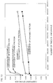
- the initial amount of play was 2.8 minutes, and the amount of play was increased to 8 minutes in approximately 400,000 times of endurance.
- the amount of play at the start of endurance was 0.3 minutes, and an increase in the amount of play was significantly gentle even via the number of times of endurance.
- the amount of play was 2.5 minutes even via 400, 000 times of endurance. This proved that a state where there is little backlash was maintained over a long period of time.
- the coefficient of friction was calculated based on the result of measuring a sliding load when a torque of 30 N ⁇ m was loaded to an actual spline product.
- An initial coefficient of dynamic friction and an initial coefficient of static friction were greater than a coefficient of dynamic friction and a coefficient of static friction in the example 1 by 50 % or more.
- the coefficient of dynamic friction and the coefficient of static friction were greatly increased in approximately 40,000 numbers of endurance.
Description
- The present invention relates to a spline telescopic shaft, a method for manufacturing the spline telescopic shaft, and a vehicle steering apparatus.
- A telescopic shaft for vehicle steering in which a surface hardened layer is provided on a surface of fitted teeth by shot peening processing, and a large number of minute recesses are formed on the surface hardened layer has been proposed (see, e.g., Japanese Patent Application Laid-Open No.
2005-153677 -
JP 2009 168194 A - A female spline manufacturing method including a process for forming a groove in a circumferential direction to be a basis of an oil reservoir on an inner peripheral surface of a hollow cylindrical material and a process for forming a female spline by plasticity processing on the inner peripheral surface of the hollow cylindrical material having the groove formed therein has been proposed (see, e.g., Japanese Patent Application Laid-Open No.
2006-207639 - In this type of spline telescopic shaft, tooth surfaces of an inner shaft and an outer shaft may be respectively provided with resin coatings. However, backlash in a rotation direction is produced between the inner shaft and the outer shaft due to the effect of a variation in dimensional precision between both the shafts. In order to reduce the backlash, the inner shaft and the outer shaft are selected depending on the dimensional precision and combined with each other so that a fitting clearance between both the shafts becomes suitable (so-called matching assembly).
- Even if no backlash is produced between both the shafts in the early stages of use, however, backlash between both the shafts is rapidly increased when a period of time for the use has elapsed.
- The present invention is defined as in the claims. A spline telescopic shaft capable of maintaining highly accurate fitting over a long period of time between first and second shafts and a method for manufacturing the spline telescopic shaft are provided. The present invention is further directed to providing a vehicle steering apparatus capable of maintaining a good steering feeling over a long period of time.
- The inventor of the present application has paid attention to the following points in solving the above-mentioned problems. Even if a resin coating is provided on one of tooth surfaces of splines in first and second shafts, there are a region where a clearance between the tooth surfaces is large and a region where the clearance is small when viewing at a surface roughness level the tooth surfaces in the early stages of use. Therefore, backlash between both the shafts is regulated only by the region where the clearance is small with an actual contact area between both the tooth surfaces being narrow. In the use for a relatively short time from the early stages thereof, therefore, the resin coating in the region where the space is small (corresponding to a region where the actual contact area is small) wears in the early stages, to reach in the early stages a state where an amount of the clearance between both the tooth surfaces is large. As a result, backlash between both the shafts is increased in the early stages. In other words, the inventor has supposed the backlash is increased in a short time from the early stages of use because the resin coating rapidly wears until both the tooth spaces are fitted to each other at a surface roughness level.
- According to one aspect, a spline telescopic shaft includes a first shaft and a second shaft that are fitted to each other slidably in an axial direction, a first spline and a second spline that are respectively provided in the first shaft and the second shaft and engage with each other, and a resin coating that is provided on at least a tooth surface of the first spline and is fitted to a tooth surface of the second spline. The resin coating is subjected to heat fitting processing for fitting the surface of the resin coating to the tooth surface of the second spline by sliding the first shaft and the second shaft in the axial direction, wherein the heat fitting processing includes heating and melting only a surface layer portion of the resin coating to a temperature that is a melting point or more of the resin composing the resin coating by heat including frictional heat generated by the relatively axially sliding of the first shaft and the second shaft.
- In the one aspect, the resin coating that has been subjected to the heat fitting processing for the tooth surface of the second spline with a zero or negative fitting clearance therebetween on at least the tooth surface of the first spline. Therefore, the fitting clearance between corresponding tooth surfaces of the first and second splines in the early stages of use can be made substantially zero (e.g., 10 um or less, preferably 5 um or less) at a surface roughness level (a level of the size of irregularities caused by a striped processing trace in an axial direction produced on the tooth surface when spline processing is performed). More specifically, an actual contact area between both the tooth surfaces can be significantly widened at a surface roughness level. As a result, a highly accurate fitted state between the first shaft and the second shaft can be realized. Therefore, backlash between both the shafts can be prevented from being produced over a long period of time.
- The tooth surfaces of the first spline and the second spline may be fitted to each other with a zero or negative fitting clearance therebetween.
- The surface of the resin coating in a stage before the heat fitting processing may be formed by the tooth surface of the second spline or a tool. In this case, the fitting space during the heat fitting processing can be set with high accuracy. An example of the tool is a surface broach (a broach for giving a required shape to an outer surface of a workpiece).
- In another aspect, the fitting clearance between the corresponding tooth surfaces of the first spline and the second spline may be 10 µm or less. More specifically, the fitting clearance between the tooth surfaces can be substantially 10 µm or less by using the resin coating that has been subjected to the heat fitting processing. As a result, a highly accurate fitted state between the first shaft and the second shaft can be realized.
- A groove extending in a direction crossing the axial direction may be formed on the surface of the resin coating. Further, at least a part of abrasion powder composed of resin produced when the heat fitting processing is performed may be contained in the groove.
- In the heat fitting processing for fitting the resin coating to a counterpart using frictional heat generated by the sliding, for example, the resin softened by frictional heat is incorporated into the groove to extend in a sliding direction so that an unnecessary portion (a portion to be removed) of the softened resin is efficiently removed.
- As the resin is softened, abrasion power in a roller shape that has been detached from the resin coating may be produced. In the present aspect, the abrasion powder does not roughen the surface of the resin coating because it can be incorporated into the groove. As a result, the resin coating can be fitted to the counterpart in a relatively smooth state. Therefore, a substantial contact area between the tooth surfaces of the first and second splines can be increased. As a result, a spline telescopic shaft that is superior in sliding properties and durability can be realized. Since the groove functions as a lubricant reservoir, a good lubricated state can be maintained for a long period of time.
- According to another aspect, a method for manufacturing a spline telescopic shaft having a first shaft and a second shaft that are fitted to each other slidably in an axial direction includes a step of forming an intermediate member for manufacturing the first shaft having a first spline, a surface forming step for processing a resin layer formed on at least a tooth surface of the first spline in the intermediate member for manufacturing the first shaft using the second shaft or a tool, to obtain a resin coating having a molded surface, wherein after the surface forming step a heat fitting processing step for sliding the intermediate member for manufacturing the first shaft is performed which enables the first shaft to be slid relatively to the second shaft in the axial direction , such that a surface of the resin coating is fitted to a tooth surface of the second spline in the second shaft.
- In this aspect, the resin coating having the molded surface is obtained by pushing the first shaft manufacturing intermediate member, in which the resin layer is formed on at least the tooth surface of the first spline in the first shaft serving as an inner shaft, for example, into a surface broach serving as the second shaft serving as an outer shaft, for example, or a tool (a broach for giving a required shape to an outer surface of a workpiece), to cut off the resin layer. Alternatively, the resin coating having the molded surface is obtained by pushing the second shaft serving as an inner shaft, for example, into the first shaft manufacturing intermediate member, in which the resin coating is formed on at least the tooth surface of the first spline in the first shaft serving as an outer shaft, for example, to cut off the resin layer or cutting off the resin layer using an internal broach serving as a tool (a broach for giving a required shape to an inner surface of a workpiece).
- Then, a resin coating having a surface that has been fitted at a surface roughness level to the tooth surface of the second spline in the second shaft can be obtained by relatively sliding the manufacturing intermediate member and the second shaft after the surface forming process. Therefore, the fitting clearance between the corresponding tooth surfaces of the first and second splines in the early stages of use can be made substantially zero at a source roughness level. More specifically, an actual contact area between both the tooth surfaces can be significantly widened at a surface roughness level. As a result, a highly accurate fitted state between the first and second shafts can be realized. Therefore, backlash between both the shafts can be prevented from being produced over a long period of time.
- The heat fitting processing step includes the step of heating and melting only a surface layer portion of the resin coating to a temperature that is a melting point or more of the resin composing the resin coating by heat including frictional heat generated by the sliding between the first shaft and the second shaft. In this case, frictional heat generated by the resin coating itself is used to heat the resin coating. Therefore, no external heating means is required so that a manufacturing facility can be simplified. The higher surface pressure for a counterpart is in the resin coating, the higher frictional heat to be generated becomes. More specifically, higher frictional heat can be obtained in an area where the resin is to be softened. Therefore, the resin coating can be effectively fitted to the shape of the counterpart.
- A vehicle steering apparatus for transmitting a steering force using the spline telescopic shaft can maintain a good steering feeling over a long period of time, and can reduce noise generated by a rattle sound over a long period of time.
-
-
Fig. 1 is a schematic view illustrating a schematic configuration of a vehicle steering apparatus having an intermediate shaft serving as a spline telescopic shaft according to an embodiment of the present invention. -
Fig. 2 is a partially broken side view of an intermediate shaft. -
Fig. 3 is a cross-sectional view taken along a line III-III illustrated inFig. 2 . -
Figs. 4A to 4H are schematic views sequentially illustrating processes for manufacturing an intermediate shaft. -
Figs. 5A to 5E, 5I, 5J, and 5F to 5H are schematic views illustrating processes for manufacturing an intermediate shaft serving as a spline telescopic shaft according to an embodiment of the present invention. -
Fig. 6 is a cross-sectional view of an inner shaft manufacturing intermediate member having grooves illustrated inFig. 5J formed therein. -
Fig. 7 is a perspective view as viewed in a direction B illustrated inFig. 6 , illustrating tooth surfaces. -
Fig. 8 is a schematic view of a method for subjecting a resin coating to groove processing using a laser. -
Figs. 9A to 9C, 9E1, 9E2, 9D, and 9F to 9H are schematic views illustrating processes for manufacturing an intermediate shaft serving as a spline telescopic shaft. -
Fig. 10A is a schematic view illustrating a relationship between a contour shape on the inner periphery of a surface broach used in a broaching process illustrated inFig. 9E1 and a contour shape of an internal spline in an outer shaft, andFig. 10B is a schematic view illustrating a relationship between a contour shape
of a surface of a resin coating molded with the surface broach and a contour shape of an internal spline in an outer shaft. -
Figs. 11A to 11C, 11E1, 11E2, 11I, 11J, 11D, and 11F to 11H are schematic views illustrating processes for manufacturing an intermediate shaft serving as a spline telescopic shaft according to a further embodiment of the present invention. -
Fig. 12 is a graph illustrating a relationship between the number of times of endurance and an amount of play. -
Fig. 13 is a graph illustrating a relationship between the number of times of endurance and a coefficient of friction. - Preferred embodiments of the present invention will be described with reference to the accompanying drawings.
-
Fig. 1 is a diagram illustrating a schematic configuration of a vehicle steering apparatus having an intermediate shaft to which a spline telescopic shaft according to an embodiment of the present invention is applied. Referring toFig. 1 , thevehicle steering apparatus 1 includes asteering shaft 3 connected to asteering member 2 such as a steering wheel, and anintermediate shaft 5 serving as a spline telescopic shaft connected to thesteering shaft 3 via auniversal joint 4. Thevehicle steering apparatus 1 includes apinion shaft 7 connected to theintermediate shaft 5 via auniversal joint 6, and arack shaft 8 serving as a steering shaft having arack 8a that engages with apinion 7a provided in the vicinity of an end of thepinion shaft 7. A rack-and-pinion mechanism including thepinion shaft 7 and therack shaft 8 constitutes a steering mechanism A1. Therack shaft 8 is supported movably in an axial direction (a direction perpendicular to paper) in a right-and-left direction of a vehicle by ahousing 10 fixed to avehicle body member 9. Each of ends of therack shaft 8 is connected to a corresponding steering wheel via a corresponding tie rod and a corresponding knuckle arm, which is not illustrated. - The steering
shaft 3 includes afirst steering shaft 11 and asecond steering shaft 12 that are coaxially connected to each other. Thefirst steering shaft 11 includes anupper shaft 13 and alower shaft 14. Theupper shaft 13 and thelower shaft 14 are fitted to each other together rotatably and relatively slidably in an axial direction using spline coupling. Either one of theupper shaft 13 and thelower shaft 14 constitutes an inner shaft, and the other shaft constitutes a cylindrical outer shaft. - The
second steering shaft 12 includes aninput shaft 15 connected to thelower shaft 14 together rotatably, anoutput shaft 16 connected to theintermediate shaft 5 via theuniversal joint 4, and atorsion bar 17 connecting theinput shaft 15 and theoutput shaft 16 to each other relatively rotatably. - The steering
shaft 3 is rotatably supported via a bearing (not illustrated) by asteering column 20 fixed tovehicle body members - The
steering column 20 includes a cylindricalupper jacket 21 and a cylindricallower jacket 22 that are fitted to each other relatively movably in the axial direction, and ahousing 23 connected to a lower end in the axial direction of thelower jacket 22. Thehousing 23 houses aspeed reduction mechanism 25 for decelerating power of anelectric motor 24 for steering assist and transmitting the power to theoutput shaft 16. - The
speed reduction mechanism 25 includes adriving gear 26 that is connected to a rotating shaft (not illustrated) of theelectric motor 24 together rotatably, and a drivengear 27 that engages with thedriving gear 26 and rotates together with theoutput shaft 16. Thedriving gear 26 is composed of a worm shaft, for example, and the drivengear 27 is composed of a worm wheel, for example. - The
steering column 20 is fixed to thevehicle body members upper bracket 28 on the back side of the vehicle and alower bracket 29 on the front side of the vehicle. Theupper bracket 28 can be fixed to theupper jacket 21 in thesteering column 20 via a column bracket, described below. Theupper bracket 28 is fixed to the vehicle body-side member 18 using a fixed bolt (stud bolt) 30 projecting downward from the vehicle body-side member 18, a nut 31 screwed into the fixed bolt 30, and acapsule 32 detachably held in theupper bracket 28. - The
lower bracket 29 is fixed to thelower jacket 22 in thesteering column 20. Thelower bracket 29 is fixed to the vehicle body-side member 19 using a fixed bolt (stud bolt) 33 projecting from thevehicle body member 19 and anut 34 screwed into the fixedbolt 33. - Referring to
Figs. 1 and2 , theintermediate shaft 5 serving as the spline telescopic shaft is formed by spline-fitting theinner shaft 35 and the cylindricalouter shaft 36 to each other slidably in the axial direction X1 and torque-transmittably. Either one of theinner shaft 35 and theouter shaft 36 constitutes an upper shaft, and the other shaft constitutes a lower shaft. In the present embodiment, theouter shaft 36 is connected to theuniversal joint 4 as the upper shaft, and theinner shaft 35 is connected to theuniversal joint 6 as the lower shaft. - Although in the present embodiment, the spline telescopic shaft is applied to the
intermediate shaft 5, the spline telescopic shaft according to the present invention may be applied to thefirst steering shaft 11, and thefirst steering shaft 11 may perform a telescopic adjustment function and a shock absorption function. Although in the present embodiment, thevehicle steering apparatus 1 is an electric power steering apparatus, the spline telescopic shaft according to the present invention may be applied to a steering apparatus for a manual steering vehicle. - Referring to
Figs. 2 and3 , anexternal spline 37 provided on theouter periphery 35a of theinner shaft 35, and aninternal spline 38 provided on theinner periphery 36a of theouter shaft 36. The present embodiment is characterized in that aresin coating 39 having asurface 39a that has been subjected to heat fitting processing (seeFig. 4F ) for theouter shaft 36 is formed on at lest atooth surface 37a of theexternal spline 37, as illustrated inFig. 3 . More specifically, at least a part of theresin coating 39 with which the periphery of acore 350 of theinner shaft 35 is coated forms at least thetooth surface 37a of theexternal spline 37. - In the present invention, out of first and second shafts that are fitted to each other slidably in the axial direction, at least a tooth surface of a first spline in the first shaft is provided with a resin coating. The first shaft is either one of the
inner shaft 35 and theouter shaft 36. Although in the present embodiment, theresin coating 39 is formed on at least thetooth surface 37a of theexternal spline 37 serving as a first spline in theinner shaft 35 serving as a first shaft, a resin coating may be formed on at least atooth surface 38a of theinternal spline 38 serving as a first spline in theouter shaft 36 serving as a first shaft. - Processes for manufacturing the
intermediate shaft 5 will be described with reference to schematic views ofFigs. 4A to 4H . - First, in a casting process illustrated in
Fig. 4A , a material is cast, to obtain an inner shaft manufacturingintermediate member 41 having anexternal spline 40 formed thereon. - Then, in a preprocessing process illustrated in
Fig. 4B , at least a tooth surface of theexternal spline 40 on the inner shaft manufacturingintermediate member 41 illustrated inFig. 4A is subjected to preprocessing for coating. More specifically, base processing such as shot blasting or primer coating is performed to smooth the tooth surface as processing in a stage preceding a stage in which aresin layer 44 is formed in a coating process illustrated inFig. 4C , described below. Thus, an inner shaft manufacturing intermediate member 43 (corresponding to thecore 350 in the inner shaft 35), having anexternal spline 42 at least a tooth surface of which has been subjected to preprocessing, formed thereon, as illustrated inFig. 4B , is obtained. - Then, in the coating process illustrated in
Fig. 4C , theresin layer 44 is formed on at least the tooth surface of theexternal spline 42 on the inner shaft manufacturingintermediate member 43 illustrated inFig. 4B , to obtain an inner shaft manufacturingintermediate member 45 having theresin layer 44 formed thereon, as illustrated inFig. 4C . More specifically, the inner shaft manufacturingintermediate member 43 that has been subjected to preprocessing is heated, and is then dipped for a predetermined period of time in a dipping tank including fluidized resin powder. Thus, the resin power is melted by heat after adhering to the inner shaft manufacturingintermediate member 43, to form theresin layer 44. A cross section on the outer periphery of theresin layer 44 forms a circular shape or a substantially circular shape. Examples of resin forming theresin layer 44 include thermoplastic resin such as polyamide or polyacetal. Theresin layer 44 may be injection-molded. - Then, in a jointing process illustrated in
Fig. 4D , theuniversal joint 4 is connected to an end of the inner shaft manufacturingintermediate member 45. - Then, in a broaching process illustrated in
Fig. 4E , the inner shaft manufacturingintermediate member 45 having theresin layer 44 formed thereon is broached into theouter shaft 36 serving as a counterpart shaft. Thus, an inner shaft manufacturingintermediate member 47 having theresin coating 39 formed thereon, as illustrated inFig. 4F , is obtained by atooth surface 38a of aninternal spline 38 in theouter shaft 36. In the broaching process, when the inner shaft manufacturingintermediate member 45 is broached, anexcess portion 44a of theresin layer 44 is cut off, and is discharged out of theouter shaft 36 serving as the counterpart shaft in a manner of wood shavings. - Then, in a heat fitting process illustrated in
Fig. 4F , the inner shaft manufacturingintermediate member 47 that has been inserted into theouter shaft 36 serving as the counterpart shaft is forcibly slid relative to theouter shaft 36, to complete theinner shaft 35 coated with theresin coating 39 having asurface 39a fitted to thetooth surface 38a of theinternal spline 38 in theouter shaft 36. - In the heat fitting process, frictional heat generated by the forced sliding between the
outer shaft 36 serving as the counterpart shaft and the inner shaft manufacturingintermediate member 47 is used, to heat and melt a surface layer portion of theresin coating 39 that contacts theouter shaft 36 to a temperature that is a melting point or more of the resin composing theresin coating 39. Theresin coating 39 is fitted to theinternal spline 38 in theouter shaft 36 while promoting softening of the resin in a heated state, and is then cooled. Thus, thesurface 39a of theresin coating 39 can be fitted to thetooth surface 38a of theinternal spline 38 in theouter shaft 36 at a surface roughness level. This completes theinner shaft 35. - In a grease coating process illustrated in
Fig. 4G , thesurface 39a of theresin coating 39 on theinner shaft 35 is coated withgrease 48. Theinner shaft 35 coated with thegrease 48 is incorporated into theouter shaft 36, to complete theintermediate shaft 5 serving the spline telescopic shaft, as illustrated inFig. 4H . - In the method for manufacturing the spline telescopic shaft (intermediate shaft 5) according to the present embodiment, the inner shaft manufacturing
intermediate member 45 having theresin layer 44 formed thereon is pushed into theouter shaft 36 serving as the counterpart shaft, to obtain the inner shaft manufacturingintermediate member 47 having theresin coating 39 on at least thetooth surface 37a of theexternal spline 37, and the inner shaft manufacturingintermediate member 47 is then forcibly slid relative to theouter shaft 36. Thus, theinner shaft 35 having theresin coating 39 having thesurface 39a, which has been fitted at a surface roughness level to thetooth surface 38a of theinternal spline 38 in theouter shaft 36, formed thereon can be obtained. - More specifically, in the spline telescopic shaft (intermediate shaft 5) according to the present embodiment, the
resin coating 39 that has been subjected to the heat fitting processing for thetooth surface 38a of theinternal spline 38 with a zero or negative fitting clearance therebetween is formed on at least thetooth surface 37a of theexternal spline 37. Therefore, a fitting clearance between the tooth surfaces 37a and 38a of both thesplines - More specifically, an actual contact area between both the tooth surfaces 37a and 38a can be significantly widened at a surface roughness level. As a result, a highly accurate fitted state between the
inner shaft 35 and theouter shaft 36 can be realized. Therefore, backlash between theinner shaft 35 and theouter shaft 36 can be prevented from being produced over a long period of time. This enables a good steering feeling to be obtained over a long period of time while enabling noise generated by a rattle sound between the tooth surfaces 37a and 38a to be reduced. Quietness can be improved by preventing so-called stick slip between theinner shaft 35 and theouter shaft 36. - As sliding conditions between the inner shaft manufacturing
intermediate member 47 and theouter shaft 36 when frictional heat generated by forced sliding between the inner shaft manufacturingintermediate shaft 47 and theouter shaft 36 is used to heat the inner shaft manufacturingintermediate member 47 in the heat fitting process illustrated inFig. 4F , a sliding stroke between the inner shaft manufacturingintermediate member 47 and theouter shaft 36 is in a range of ± 10 mm to ± 50 mm, and a sliding frequency is 1.5 Hz to 10 Hz. - The necessity of an external heating unit is eliminated by using frictional heat so that a manufacturing facility can be simplified. The higher surface pressure for the counterpart is on the
surface 39a of theresin coating 39, the higher frictional heat to be generated becomes. More specifically, higher frictional heat can be obtained in a region where the resin is to be softened, so that theresin coating 39 can be effectively fitted to the shape of the counterpart. - When the heat fitting processing is performed using frictional heat, the inner shaft manufacturing
intermediate member 47 and theouter shaft 36 can be slid at a long sliding stroke (± 30 mm or more) and at high speed (2 Hz or more) to perform the heat fitting processing at high efficiency. This is for the following reasons. More specifically, when the sliding stroke is lengthened, a heat transmission area is increased. Therefore, an amount of heat transfer relative to an amount of heat generation is increased so that a temperature rise of theouter shaft 36 can be suppressed. Thus, a ratio of the amount of heat generation to the amount of heat transfer (amount of heat dissipation) is decreased. As a result, the thickness of a softened layer is decreased. Therefore, production of abrasion power in a roller state can be suppressed so that a tooth surface can be stably formed. - In the heat fitting process, the
outer shaft 36 and the inner shaft manufacturingintermediate member 47 may be heated by an external heater (not illustrated) in place of heating by frictional heat. When theouter shaft 36 and the inner shaft manufacturingintermediate member 47 are heated by an external heater, the temperature of heat to be applied from the exterior is set to a melting point or less of the resin, to forcibly slide the inner shaft manufacturingintermediate member 47 and theouter shaft 36 so that only the surface layer portion of theresin coating 39 reaches a temperature that is the melting point or more of the resin. - As described above, in the heat fitting process using frictional heat and an external heater, a groove forming process illustrated in
Fig. 5I may be included between a broaching process illustrated inFig. 5E and a heat fitting process illustrated inFig. 5F , as illustrated inFigs. 5A to 5H . Processes illustrated inFigs. 5A to 5E respectively correspond to the processes illustrated inFigs. 4A to 4E , and processes illustrated inFigs. 5F to 5H respectively correspond to the processes illustrated inFigs. 4F to 4H . - In the groove forming process illustrated in
Fig. 5I , thesurface 39a of theresin coating 39 is irradiated with a laser 51 (e.g., a YVO4 laser or a CO2 laser) in a direction crossing the axial direction X1 from alaser irradiation unit 50, to thermally decompose a part of the resin and remove the resin. Thus, an inner shaft manufacturingintermediate member 147 having aresin coating 139 having a continuouslyspiral groove 52, as illustrated inFig. 5J , formed therein is obtained. - The
groove 52 is formed to a predetermined depth from asurface 139a of theresin coating 139, as illustrated in a cross-sectional view ofFig. 6 illustrating the inner shaft manufacturingintermediate member 147 and a perspective view ofFig. 7 taken along a line B illustrated inFig. 6 (corresponding to a diagram as viewed in a direction opposite totooth surfaces 37a of external spline teeth 370). - The
groove 52 extends to cross each of theexternal spline teeth 370 in the inner shaft manufacturingintermediate member 147. As illustrated inFig. 7 , parts of thegrooves 52 forming a spiral shape are arranged with predetermined spacing in the axial direction X1 of the inner shaft manufacturingintermediate member 45 on the tooth surfaces 37a of theexternal spline teeth 370, and extend in a direction Z1 inclined at a predetermined angle to a radial direction of the inner shaft manufacturingintermediate member 45. - The
grooves 52 may be continuously formed, or may be intermittently formed. Although thegrooves 52 may form a spiral shape, as described above, a plurality of annular grooves extending in a circumferential direction of theinner shaft 35 may be spaced apart in the axial direction X1, which is not illustrated. - The
groove 52 is formed on the onetooth surface 37a of theexternal spline tooth 370 by irradiating thelaser 51 in an irradiation direction R1 perpendicular to an axial direction Y1 (a direction perpendicular to paper) of the inner shaft manufacturingintermediate member 45 from thelaser irradiation unit 50 at a position indicated by a solid line inFig. 8 and relatively moving thelaser 51 and the inner shaft manufacturingintermediate member 45 in the axial direction Y1 while rotating the inner shaft manufacturingintermediate member 45, for example. - The
laser irradiation unit 50 is then displaced to a position indicated by a two-dot and dash line illustrated inFig. 8 by parallel displacement in a direction perpendicular to the irradiation direction R1, to irradiate thelaser 51 in an irradiation direction R2 perpendicular to the axial direction Y1 of the inner shaft manufacturingintermediate member 45. Thelaser 51 and the inner shaft manufacturingintermediate member 45 are relatively moved in the axial direction Y1 while rotating the inner shaft manufacturingintermediate member 45, to form thegroove 52 on theother tooth surface 37a of theexternal spline tooth 370. - In
Fig. 8 , the position indicated by the solid line and the position indicated by the two-dot and dash line of thelaser irradiation unit 50 are symmetric with respect to a plane P1 including a central axis C1 of the inner shaft manufacturingintermediate member 45 and parallel to the irradiation direction R1 of thelaser 51. - Processing by the
laser 51 may be replaced with fine groove processing by water jets or compressed air including hard fine particles. - The following is the meaning that the
groove 52 is provided. More specifically, in the heat fitting process illustrated inFig. 5E for fitting theresin coating 139 in a heated state by frictional heat or an external heater to thetooth surface 38a of theinternal spline 38 in theouter shaft 36, softened resin receives shearing resistance between thetooth surface 38a in theouter shaft 36 and unsoftened resin, so that abrasion power in a roller shape detached in a manner of bits of eraser grit from thesurface 139a of theresin coating 139 may be produced. On the other hand, thegroove 52 is provided on thesurface 139a of theresin coating 139 so that the abrasion power can be incorporated into thegroove 52. Therefore, no abnormal abrasion occurs on thesurface 139a of theresin coating 139, that is, thesurface 139a is not roughened by making the abrasion power huge. Thus, thesurface 139a of theresin coating 139 can be fitted to the counterpart in a relatively smooth state. - Therefore, a substantial contact area between the tooth surfaces 37a and 38a of the
external spline 37 and theinternal spline 38 can be increased. As a result, the intermediate shaft 5 (or the first steering shaft 11) serving as the spline telescopic shaft that is superior in sliding properties and superior in durability can be realized. When theintermediate shaft 5 is used, thegroove 52 functions as a lubricant reservoir. Therefore, a good lubricated state can be maintained for a long period of time. - The depth of the
groove 52 can be at least one of 50 % or more or 0.1 mm or more of the thickness of theresin coating 139. The groove width of the groove 52 (the width of thegroove 52 in the axial direction X1) can be 0.2 mm or more and 1 mm or less. - A space between the
grooves 52 in the axial direction X1 can be one to ten times the height of spline teeth. - According to the embodiment illustrated in
Figs. 5A to 5H , a similar function effect as that in the embodiment illustrated inFigs. 4A to 4H can be produced. More specifically, theresin coating 139 that has been subjected to heat fitting processing for thetooth surface 38a of theinternal spline 38 with a zero or negative fitting clearance therebetween is formed on at least thetooth surface 37a of theexternal spline 37. Therefore, the fitting clearance between the tooth surfaces 37a and 38a of both thesplines inner shaft 35 and theouter shaft 36 can be realized. Therefore, backlash between theinner shaft 35 and theouter shaft 36 can be prevented from being produced over a long period of time. This enables a good steering feeling to be obtained over a long period of time while enabling noise generated by a rattle sound between the tooth surfaces 37a and 38a to be reduced. Quietness can be improved by preventing so-called stick slip between theinner shaft 35 and theouter shaft 36. - Particularly when the heat fitting processing using frictional heat is performed, a manufacturing facility can be simplified. In the heat fitting processing, however, heating using an external heater may be used. Since the
groove 52 is provided in theresin coating 139 that has not been subjected to the heat fitting processing using frictional heat or an external heater, the abrasion power produced in the heat fitting process can be incorporated into thegroove 52. Therefore, thesurface 139a of theresin coating 139 can be made smoother. This enables a more highly accurate fitted state between theinner shaft 35 and theouter shaft 36 to be realized, thereby more reliably preventing backlash between theinner shaft 35 and theouter shaft 36 to be produced over a long period of time. Therefore, a good steering feeling can be obtained over a long period of time. Further, noise generated by a rattle sound between the tooth surfaces 37a and 38a can be further reduced. Quietness can be improved by reliably preventing so-called stick slip between theinner shaft 35 and theouter shaft 36. -
Figs. 9A and 9H illustrate a method for manufacturing an intermediate shaft serving as a spline telescopic shaft in still another embodiment of the present invention. The following is a difference between the embodiment illustrated inFigs. 9A to 9H and the embodiment illustrated inFigs. 4A to 4H . More specifically, in the embodiment illustrated inFigs. 4A to 4H , in the broaching process illustrated inFig. 4E after the jointing process illustrated inFig. 4D , the inner shaft manufacturingintermediate member 45 is pushed into theouter shaft 36 serving as the counterpart shaft to form theresin coating 39 by cutting off theresin layer 44. On the other hand, in the embodiment illustrated inFigs. 9A to 9H , an inner shaft manufacturingintermediate member 45 is pushed into an annular surface broach 46 for forming an inner shaft in order to form aresin coating 39 by cutting off aresin layer 44 in a broaching process illustrated inFig. 9E1 before a jointing process illustrated inFig. 9D . - The surface broach means a broach for giving a required shape on an outer surface of a workpiece. On the other hand, a broach for giving a required shape to an inner surface of the workpiece is referred to as an internal broach.
- In the broaching process illustrated in
Fig. 9E1 , anexcess portion 44a of theresin layer 44 is cut off by a tooth surface of aninternal spline 46a on the inner periphery of thesurface broach 46, to obtain an inner shaft manufacturingintermediate member 47 having aresin coating 39 formed thereon, as illustrated inFig. 9E2 . The inner shaft manufacturingintermediate member 47 is inserted into anouter shaft 36 serving as a counterpart shaft in a heat fitting process illustrated inFig. 9F via a jointing process illustrated inFig. 9D , to perform heat fitting processing. In the heat fitting process illustrated inFig. 9F , theouter shaft 36 and the inner shaft manufacturingintermediate member 47 may be heated by frictional heat, or may be heated by an external heater (not illustrated). - In the embodiment illustrated in
Figs. 9A to 9H , the dedicated surface broach 46 is used in the broaching process illustrated inFig. 9E in addition to producing a similar function effect to that illustrated inFigs. 4A to 4H . Therefore, theresin layer 44 can be efficiently cut off. - When the
resin coating 39 is formed by cutting off theresin layer 44 on the inner shaft manufacturingintermediate member 45 using the surface broach 46 as in the present embodiment, a contour shape Q1 on the inner periphery of the surface broach 46 illustrated inFig. 10A (which is matched with a contour shape Q2 on a surface of aresin coating 39 illustrated inFig. 10B ) has the following relationship with a contour shape Q3 of aninternal spline 38 in the outer shaft 36 (corresponding to atooth surface 38a, a large-diameter portion 38b, and a small-diameter portion 38c). - More specifically, referring to
Fig. 10B , in the contour shape Q2 of the resin coating 39 (which is matched with the contour shape Q1 of the surface broach 46), a tooth surface Q21 serving as a torque transmission surface is processed to such a size that the correspondingtooth surface 38a of theinternal spline 38 in theouter shaft 36 and the tooth surface Q21 can be fitted to each other (i.e., pressed into each other) with a negative space therebetween. - The
resin coating 39 is processed to such a size that a space S1 is provided between the large-diameter portion 38b (corresponding to the tooth bottom) of theinternal spline 38 and a large-diameter portion Q22 of the contour shape Q2 on the surface of the resin coating 39 (corresponding to the tooth tip of anexternal spline 37 in aninner shaft 35 and matched with a large-diameter portion Q12 of the contour shape Q1 on the inner periphery of the surface broach 46), and a space S2 is provided between a small-diameter portion 38c (corresponding to the tooth tip) of theinternal spline 38 and a small-diameter portion Q23 of the contour shape Q2 on the surface of the resin coating 39 (corresponding to the tooth bottom of theexternal spline 37 in theinner shaft 35 and matched with a small-diameter portion Q13 of the contour shape Q1 on the inner periphery of the surface broach 46). - In a process for pressing the inner shaft manufacturing
intermediate member 47 having theresin coating 39 processed with the surface broach 46 having the above-mentioned shape into theouter shaft 36 serving as the counterpart shaft, an actual contact portion is only the tooth surface Q21 serving as a torque transmission surface, and the large-diameter portion Q22 and the small-diameter portion Q23 enter a noncontact state, as illustrated inFig. 10B . Therefore, a load at which the inner shaft manufacturingintermediate member 47 is to be pressed into theouter shaft 36 can be reduced so that the inner shaft manufacturingintermediate member 47 can be easily pressed into theouter shaft 36. - In the heat fitting process, a sliding load is also reduced. Therefore, the heat fitting processing can be performed with a relatively small equipment capacity. Even if the large-diameter portion Q22 and the small-diameter portion Q23 are negatively spaced apart from the
internal spline 38 in theouter shaft 36, a facility having a sufficient capacity can execute the heat fitting processing without any problem. -
Figs. 11A and 11H illustrate a method for manufacturing an intermediate shaft serving as a spline telescopic shaft according to still another embodiment of the present invention. The embodiment illustrated inFigs. 11A to 11H differs from the embodiment illustrated inFigs. 9A to 9H in that a groove is formed in the inner shaft manufacturingintermediate member 47 that has passed through a broaching process illustrated inFig. 11E1 in a groove forming process illustrated inFig. 11I , to obtain an inner shaft manufacturingintermediate member 147 on which aresin coating 139 havinggrooves 52 formed thereon is formed, as illustrated inFig. 11J . - Processes illustrated in
Figs. 11A to 11E1 and 11E2 respectively correspond to the processes illustrated inFigs. 9A to 9E1 and 9E2 , and processes illustrated inFigs. 11D to 11H respectively correspond to the processes illustrated inFigs. 9D to 9H . The groove forming process illustrated inFig. 11I corresponds to the groove forming process illustrated inFig. 5I . - In the embodiment illustrated in
Figs. 11A to 11H , a similar function effect to that in the embodiment illustrated inFigs. 9A to 9H is produced, and thegrooves 52 are formed in theresin coating 139 before heat fitting processing, as in the embodiment illustrated inFigs. 5A to 5H . Therefore, abrasion power composed of resin can be incorporated into thegrooves 52 in a heat fitting processing process. Therefore, no abnormal abrasion occurs on asurface 139a of theresin coating 139, that is, thesurface 139a is not roughened by making the abrasion power huge. Thus, thesurface 139a of theresin coating 139 can be fitted to a counterpart in a relatively smooth state. - Although in each of the above-mentioned embodiments, a resin coating that has been subjected to heat fitting processing for a tooth surface of an internal spline in an outer shaft with a zero or negative fitting clearance therebetween is formed on at least a tooth surface of an external spline in an inner shaft, the present invention is not limited to the same. The present invention can be implemented by forming a resin coating that has been subjected to heat fitting processing for a tooth surface of an external spline in an inner shaft with a zero or negative fitting space therebetween on at least a tooth surface of an internal spline in an outer shaft, which is not illustrated. In the case, when a resin layer formed in an internal spline in an outer shaft manufacturing intermediate member is cut off, to form a resin coating, the resin layer is cut off using an inner shaft in an actual counterpart. Alternately, the resin layer is cut off by broaching using an internal broach. Then, the outer shaft manufacturing intermediate member having the resin coating is fitted to the inner shaft in the counterpart, to perform heat fitting processing by heating by frictional heat generated by forced sliding or heating by an external heater in combination with heating by forced sliding.
- Even when the resin layer formed in the internal spline in the outer shaft manufacturing intermediate member is cut off to form the resin coating, a tooth surface serving as a torque transmission surface in the resin coating can be negatively spaced apart from a tooth surface of an external spline in the inner shaft in the counterpart, and a space can be provided between a large-diameter portion of the external spline in the inner shaft (corresponding to the tooth tip of the external spline) and a large-diameter portion of the resin coating (corresponding to the tooth bottom of the internal spline) while a space can be formed between a small-diameter portion of the external spline in the inner shaft (corresponding to the tooth bottom of the external spline) and a small-diameter portion of the resin coating (corresponding to the tooth tip of the internal spline).
- Although in each of the above-mentioned embodiments, the
vehicle steering apparatus 1 is a so-called column assist type electric power steering apparatus for applying a steering assist force to thesteering shaft 3, it may be a so-called pinion assist type electric power steering apparatus for applying a steering assist force to thepinion shaft 7, or may be a so-called rack assist type electric power steering apparatus for applying a steering assist force to therack shaft 8. It may be applied to a steering apparatus for a manual steering vehicle. The spline telescopic shaft according to the present invention is applicable as a telescopic shaft for telescopically adjusting a steering column. - The present invention will be described below based on an example and a comparative example. Example 1 and Comparative example 1
- A spline telescopic shaft in an example 1 was produced by providing an
inner shaft 35 having aresin coating 139 made of polyamide having a film thickness of 270 µm that had been subjected to heat fitting processing on a surface including atooth surface 37a of anexternal spline 37 and combining theinner shaft 35 with a correspondingouter shaft 36 via the processes illustrated inFigs. 4A to 4H . An internal spline was formed by broaching in the inner diameter of a sleeve composed of a cold forging. - A spline telescopic shaft in a comparative example 1 was produced on a tooth surface of an external spline by combining an inner shaft coated with epoxy resin that had been adjusted to a film thickness of 10 µm by machining with a corresponding outer shaft. The spline telescopic shafts in the example 1 and the comparative example 1 are similar in the material, the shape, and the size of a core of the inner shaft, and are similar in the material, the shape, and the size of the outer shaft. Durability test
- For each of the spline telescopic shafts in the example 1 and the comparative example 1, a durability test was performed under test conditions, described below, to measure amounts of play (backlash) in a rotation direction of the inner shaft and the outer shaft. A coefficient of friction between tooth surfaces was measured.
- Each of the spline telescopic shafts in the example 1 and the comparative example 1 was assembled at a mounting angle of 30° as an intermediate shaft of an actual vehicle steering apparatus, to perform a stationary steering durability test.
- Load torque : ± 50 Nm
- Rotational angle : ± 90°
- Rotational period : 0.9 Hz
- Sliding amount : ± 0.5 mm
- Test temperature : room temperature
- As a result, a relationship between the number of times of endurance (the number of repetitions) and the above-mentioned amount of play, as illustrated in
Fig. 12 , was obtained, and a relationship between the number of times of endurance and the coefficient of endurance, as illustrated inFig. 13 , was obtained. This proved the following. - Referring to
Fig. 12 , in the comparative example 1, the initial amount of play was 2.8 minutes, and the amount of play was increased to 8 minutes in approximately 400,000 times of endurance. On the other hand, in the example 1, the amount of play at the start of endurance was 0.3 minutes, and an increase in the amount of play was significantly gentle even via the number of times of endurance. Moreover, the amount of play was 2.5 minutes even via 400, 000 times of endurance. This proved that a state where there is little backlash was maintained over a long period of time. - Referring to
Fig. 13 , in the comparative example 1, the coefficient of friction was calculated based on the result of measuring a sliding load when a torque of 30 N·m was loaded to an actual spline product. An initial coefficient of dynamic friction and an initial coefficient of static friction were greater than a coefficient of dynamic friction and a coefficient of static friction in the example 1 by 50 % or more. In the comparative example 1, the coefficient of dynamic friction and the coefficient of static friction were greatly increased in approximately 40,000 numbers of endurance. - On the other hand, in the example 1, respective increases in the coefficient of dynamic friction and the coefficient of static friction were significantly gentle even via the number of times of endurance. Moreover, the coefficient of dynamic friction and the coefficient of static friction were respectively 0.11 and 0.09 even via 400,000 times of endurance. This proved that superior sliding properties were maintained over a long period of time.
- While the invention has been described in detail with respect to specific embodiments thereof, it will be appreciated that those skilled in the art, upon attaining an understanding of the foregoing, may readily conceive of alternations to, variations of, and equivalents to these embodiments. Accordingly, the scope of the present invention should be assessed as that of the appended claims.
Claims (12)
- A method for manufacturing a spline telescopic shaft (5) having a first shaft and a second shaft that are fitted to each other slidably in an axial direction (X1), the method comprising:a step of forming an intermediate member (45) for manufacturing the first shaft (35) having a first spline (42);a surface forming step for processing a resin layer (44) formed on at least a tooth surface of the first spline (42) in the intermediate member (45) for manufacturing the first shaft (35) using the second shaft (36) or a tool (46), to obtain a resin coating (39; 139) having a molded surface; whereinafter the surface forming step a heat fitting processing step for sliding the intermediate member (47; 147) for manufacturing the first shaft (35) is performed which enables the first shaft (35) to be slid relatively to the second shaft (36) in the axial direction, such that a surface (39a; 139a) of the resin coating (39; 139) is fitted to a tooth surface (38a) of the second spline (38) in the second shaft (36),characterized in thatthe heat fitting processing step includes the step of heating and melting only a surface layer portion of the resin coating (39; 139) to a temperature that is a melting point or more of the resin composing the resin coating (39; 139) by heat including frictional heat generated by the relatively axially sliding of the intermediate member for manufacturing the first shaft (35) and the second shaft (36).
- The method for manufacturing the spline telescopic shaft (5) according to claim 1, wherein corresponding tooth surfaces (37a, 38a) of the first spline (37) and the second spline (38) are fitted to each other with a zero or negative fitting clearance therebetween.
- The method for manufacturing the spline telescopic shaft (5) according to claim 1 or 2, further comprising
a groove forming step for forming a groove (52) extending in a direction crossing the axial direction (X1) on the surface (39a; 139a) of the resin coating (39; 139) between the surface forming step and the heat fitting processing step. - The method for manufacturing the spline telescopic shaft (5) according to any one of claims 1 to 3, wherein
a surface broach (45) serving as the tool processes only a tooth surface (Q21) of the intermediate member (45) for manufacturing the first shaft (35) before the surface forming step. - The method for manufacturing the spline telescopic shaft (5) according to claim 4, wherein
spaces (S1, S2) are respectively provided between a large-diameter portion (Q22) and a small-diameter portion (Q23) of the intermediate member (45) for manufacturing the first shaft (35) before the surface forming step and the surface broach (46) serving as the tool. - A spline telescopic shaft (5) produced by the method according to any one of claims 1 to 5, comprising:a first shaft (35) and a second shaft (36) that are fitted to each other slidably in an axial direction (X1);a first spline (37) and a second spline (38) that are respectively provided in the first shaft (35) and the second shaft (36) and engage with each other; anda resin coating (39; 139) that is provided on at least a tooth surface (37a) of the first spline (37) and is fitted to a tooth surface (38a) of the second spline (38),wherein a surface (39a; 139a) of the resin coating (39; 139) is fitted to the tooth surface (38a) of the second spline (38).
- The spline telescopic shaft (5) according to claim 6, wherein corresponding tooth surfaces (37a, 38a) of the first spline (37) and the second spline (38) are fitted to each other with a zero or negative fitting clearance therebetween.
- The spline telescopic shaft (5) according to claim 6, wherein
the surface (39; 139a) of the resin coating (39; 139) in a stage before the heat fitting processing is molded by the tooth surface (38a) of the second spline (38) or a tool (46). - The spline telescopic shaft (5) according to any one of claims 6 to 8,
wherein
the fitting clearance between the corresponding tooth surfaces (37a, 38a) of the first spline (37) and the second spline (38) is 10 µm or less. - The spline telescopic shaft (5) according to any one of claims 6 to 9,
wherein
a groove (52) extending in a direction crossing the axial direction (X1) is formed on the surface (39a; 139a) of the resin coating (39; 139). - The spline telescopic shaft (5) according to claim 10, wherein
at least a part of abrasion powder composed of resin produced when the heat fitting processing is performed is contained in the groove (52). - A vehicle steering apparatus (1) for transmitting a steering force using the spline telescopic shaft (5) according to any one of claims 6 to 11.
Applications Claiming Priority (1)
| Application Number | Priority Date | Filing Date | Title |
|---|---|---|---|
| JP2009184541A JP2011038560A (en) | 2009-08-07 | 2009-08-07 | Spline telescopic shaft, method of manufacturing the same, and vehicle steering apparatus |
Publications (3)
| Publication Number | Publication Date |
|---|---|
| EP2282071A2 EP2282071A2 (en) | 2011-02-09 |
| EP2282071A3 EP2282071A3 (en) | 2012-01-11 |
| EP2282071B1 true EP2282071B1 (en) | 2016-06-29 |
Family
ID=42985470
Family Applications (1)
| Application Number | Title | Priority Date | Filing Date |
|---|---|---|---|
| EP10171834.4A Active EP2282071B1 (en) | 2009-08-07 | 2010-08-04 | Spline telescopic shaft and method of manufacturing |
Country Status (3)
| Country | Link |
|---|---|
| US (1) | US8753215B2 (en) |
| EP (1) | EP2282071B1 (en) |
| JP (1) | JP2011038560A (en) |
Families Citing this family (24)
| Publication number | Priority date | Publication date | Assignee | Title |
|---|---|---|---|---|
| JP2011038560A (en) * | 2009-08-07 | 2011-02-24 | Jtekt Corp | Spline telescopic shaft, method of manufacturing the same, and vehicle steering apparatus |
| JP5408194B2 (en) * | 2010-10-11 | 2014-02-05 | 日本精工株式会社 | Telescopic shaft manufacturing method and telescopic shaft manufactured by this manufacturing method |
| DE102010049106A1 (en) * | 2010-10-21 | 2011-06-09 | Daimler Ag | Sliding sleeve blank for producing sliding sleeve for steering spindle shaft in motor vehicle-steering shaft arrangement, has cylindrical shape, and is one cold forming press component, which has preliminary gearing at one section |
| JP5867773B2 (en) * | 2011-03-18 | 2016-02-24 | 株式会社ジェイテクト | Manufacturing method of power transmission shaft |
| ES2395976B1 (en) * | 2011-08-31 | 2013-09-06 | Castellon Melchor Daumal | INTERMEDIATE AXLE FOR STEERING COLUMNS INCORPORATING OILS. |
| CN203005509U (en) * | 2011-09-26 | 2013-06-19 | 爱信精机株式会社 | Vehicle steering device |
| KR20150031274A (en) * | 2012-06-19 | 2015-03-23 | 니타 가부시키가이샤 | Structural body for shaft, male member, and female member |
| JP6205778B2 (en) * | 2012-09-19 | 2017-10-04 | 株式会社ジェイテクト | Rotation transmission device, vehicle steering device and intermediate shaft |
| US8777264B2 (en) * | 2012-10-05 | 2014-07-15 | GM Global Technology Operations LLC | Steering column assembly for a motor vehicle |
| JP6191869B2 (en) * | 2013-11-11 | 2017-09-06 | 株式会社ジェイテクト | Telescopic shaft manufacturing method |
| JP6229885B2 (en) | 2014-01-21 | 2017-11-15 | 株式会社ジェイテクト | Telescopic shaft manufacturing method |
| JP2015169285A (en) * | 2014-03-07 | 2015-09-28 | 株式会社ジェイテクト | Resin coating forming method of spline shaft and spline shaft |
| DE102014105822B4 (en) * | 2014-04-25 | 2016-03-03 | Thyssenkrupp Presta Ag | Steering shaft for a motor vehicle |
| JP6455703B2 (en) * | 2014-09-04 | 2019-01-23 | 株式会社ジェイテクト | Intermediate shaft |
| JP6489362B2 (en) * | 2015-04-03 | 2019-03-27 | 株式会社ジェイテクト | Manufacturing method of sliding shaft |
| DE102015209768B3 (en) | 2015-05-28 | 2016-10-13 | Volkswagen Aktiengesellschaft | Length adjustable shaft for a steering device of a vehicle and steering device for a vehicle |
| US9739316B2 (en) * | 2015-08-04 | 2017-08-22 | The Boeing Company | Torque tube assemblies for use with aircraft high lift devices |
| US9956985B2 (en) * | 2016-02-16 | 2018-05-01 | Steering Solutions Ip Holding Corporation | Steering shaft assembly |
| JP6622653B2 (en) * | 2016-06-06 | 2019-12-18 | 株式会社ジェイテクト | Spline telescopic shaft manufacturing method |
| US10882070B2 (en) * | 2017-03-28 | 2021-01-05 | Steering Solutions Ip Holding Corporation | Method of manufacturing a steering shaft assembly |
| US10641315B2 (en) * | 2017-04-04 | 2020-05-05 | Steering Solutions Ip Holding Corporation | Steering shaft assembly having anti-pull apart feature |
| US11053983B2 (en) | 2018-01-19 | 2021-07-06 | The Boeing Company | Torque tube assemblies for use with aircraft high lift devices |
| US11060566B2 (en) | 2018-01-19 | 2021-07-13 | The Boeing Company | Apparatus and methods for rigging a torque tube assembly in an aircraft |
| JP2021115883A (en) * | 2020-01-22 | 2021-08-10 | 株式会社ジェイテクト | Steering device and manufacturing method thereof |
Citations (1)
| Publication number | Priority date | Publication date | Assignee | Title |
|---|---|---|---|---|
| JP2001130420A (en) * | 1999-11-01 | 2001-05-15 | Kyowa Kogyo Kk | Shaft structure for steering |
Family Cites Families (29)
| Publication number | Priority date | Publication date | Assignee | Title |
|---|---|---|---|---|
| US4282764A (en) * | 1979-09-17 | 1981-08-11 | Rexnord Inc. | Rotary to linear actuator and method of making the same |
| JPH0523856Y2 (en) * | 1985-12-06 | 1993-06-17 | ||
| US5692770A (en) * | 1995-09-15 | 1997-12-02 | Breed Automotive Technology, Inc. | Modular steering wheel and airbag combination |
| JPH09105419A (en) | 1995-10-11 | 1997-04-22 | Matsui Seisakusho:Kk | Propeller shaft and manufacture thereof |
| US5969448A (en) * | 1997-07-03 | 1999-10-19 | Data Storage Institute | Electric spindle motor |
| JP3631084B2 (en) * | 1999-09-13 | 2005-03-23 | 光洋精工株式会社 | Coated product, method for producing the same, and coating apparatus |
| US7595095B2 (en) * | 2000-09-12 | 2009-09-29 | Koyo Seiko Co. | Coated article, manufacturing method therefor and coating apparatus |
| US6381933B1 (en) * | 2000-11-27 | 2002-05-07 | New Holland North America, Inc. | Shaft coupling with tapered splines for a pull-type forage harvester |
| US7008202B2 (en) * | 2001-03-08 | 2006-03-07 | The Japan Steel Works, Ltd. | Method and apparatus for forming thermoplastic resin foam |
| TW542778B (en) * | 2001-09-14 | 2003-07-21 | Sumitomo Heavy Industries | Injection apparatus |
| JP4045112B2 (en) * | 2002-03-26 | 2008-02-13 | 光洋機械工業株式会社 | Telescopic shaft and method for forming coating layer of telescopic shaft |
| JP3797304B2 (en) * | 2002-09-13 | 2006-07-19 | 日本精工株式会社 | Telescopic shaft for vehicle steering |
| WO2004113150A1 (en) * | 2003-06-20 | 2004-12-29 | Nsk Ltd. | Motor vehicle steering device |
| JP2005153677A (en) | 2003-11-25 | 2005-06-16 | Nsk Ltd | Telescopic shaft for vehicle steering |
| JP4696916B2 (en) * | 2004-01-27 | 2011-06-08 | 日本精工株式会社 | Telescopic shaft for vehicle steering |
| JP4515824B2 (en) * | 2004-05-27 | 2010-08-04 | Ntn株式会社 | High precision plain bearing |
| JP2006207639A (en) | 2005-01-26 | 2006-08-10 | Nsk Ltd | Manufacturing method of female spline shaft with oil reservoir and female spline shaft manufactured thereby |
| EP1834716B1 (en) * | 2004-11-29 | 2012-08-08 | Nsk Ltd. | Method of producing toothed transmission member having oil holders and toothed transmission member produced by the method |
| US20060130309A1 (en) * | 2004-12-22 | 2006-06-22 | Torque-Traction Technologies, Inc. | Method of manufacturing a splined member having a coating of a material applied thereto |
| US8230710B2 (en) | 2005-03-25 | 2012-07-31 | American Axle & Manufacturing, Inc. | Method for forming a slip joint assembly with coated splines |
| WO2006123602A1 (en) * | 2005-05-18 | 2006-11-23 | Ntn Corporation | Bearing and bearing device |
| US20080070707A1 (en) * | 2006-07-28 | 2008-03-20 | Nidec Sankyo Corporation | Rotor shaft and motor with rotor shaft |
| JP5098377B2 (en) * | 2007-03-13 | 2012-12-12 | 日本精工株式会社 | Telescopic shaft for vehicle steering |
| JP2008302485A (en) * | 2007-06-11 | 2008-12-18 | Tsudakoma Corp | Cooling apparatus for table plate of rotary indexing device |
| JP2009001251A (en) * | 2007-06-25 | 2009-01-08 | Jtekt Corp | Telescopic shaft for vehicle steering and steering device for vehicle equipped with the same |
| JP2009029301A (en) * | 2007-07-27 | 2009-02-12 | Jtekt Corp | Extendable shaft for steering vehicle and vehicular steering device with the same |
| JP5104332B2 (en) * | 2008-01-18 | 2012-12-19 | 日本精工株式会社 | Telescopic shaft manufacturing method and telescopic shaft manufactured by this manufacturing method |
| JP2011038560A (en) * | 2009-08-07 | 2011-02-24 | Jtekt Corp | Spline telescopic shaft, method of manufacturing the same, and vehicle steering apparatus |
| JP5453012B2 (en) * | 2009-08-07 | 2014-03-26 | 株式会社ジェイテクト | Spline telescopic shaft manufacturing method |
-
2009
- 2009-08-07 JP JP2009184541A patent/JP2011038560A/en active Pending
-
2010
- 2010-08-03 US US12/805,497 patent/US8753215B2/en active Active
- 2010-08-04 EP EP10171834.4A patent/EP2282071B1/en active Active
Patent Citations (1)
| Publication number | Priority date | Publication date | Assignee | Title |
|---|---|---|---|---|
| JP2001130420A (en) * | 1999-11-01 | 2001-05-15 | Kyowa Kogyo Kk | Shaft structure for steering |
Also Published As
| Publication number | Publication date |
|---|---|
| US20110030496A1 (en) | 2011-02-10 |
| EP2282071A2 (en) | 2011-02-09 |
| US8753215B2 (en) | 2014-06-17 |
| JP2011038560A (en) | 2011-02-24 |
| EP2282071A3 (en) | 2012-01-11 |
Similar Documents
| Publication | Publication Date | Title |
|---|---|---|
| EP2282071B1 (en) | Spline telescopic shaft and method of manufacturing | |
| US8419555B2 (en) | Spline telescopic shaft, method for manufacturing spline telescopic shaft, and vehicle steering apparatus | |
| JP5867773B2 (en) | Manufacturing method of power transmission shaft | |
| JP5967627B2 (en) | Spline telescopic shaft manufacturing method | |
| WO2011105299A1 (en) | Extendable spline shaft, vehicle steering provided with extendable spline shaft, and method for producing extendable spline shaft | |
| CA2167771C (en) | Method for making a drive line slip joint assembly | |
| JP5549658B2 (en) | Telescopic shaft manufacturing method and telescopic shaft manufactured by this manufacturing method | |
| JP5419747B2 (en) | Spline telescopic shaft manufacturing method, spline telescopic shaft and vehicle steering telescopic shaft | |
| CN107458499B (en) | Method for manufacturing spline telescopic shaft | |
| JP2003065422A (en) | Gear, reduction gear mechanism and electric power steering device | |
| JP2017025964A (en) | Telescopic shaft and manufacturing method thereof | |
| JP6057139B2 (en) | Manufacturing method of power transmission shaft | |
| JP7124891B2 (en) | Linear drive shaft for electric power steering device, electric power steering device, and manufacturing method thereof | |
| JP2005240959A (en) | Electric power steering unit and method of manufacturing the same | |
| KR100655860B1 (en) | Coating pinion shaft of steering apparatus | |
| JP2002178091A (en) | Helical gear and differential apparatus | |
| JP2011226615A (en) | Method for producing power transmission member |
Legal Events
| Date | Code | Title | Description |
|---|---|---|---|
| PUAI | Public reference made under article 153(3) epc to a published international application that has entered the european phase |
Free format text: ORIGINAL CODE: 0009012 |
|
| AK | Designated contracting states |
Kind code of ref document: A2 Designated state(s): AL AT BE BG CH CY CZ DE DK EE ES FI FR GB GR HR HU IE IS IT LI LT LU LV MC MK MT NL NO PL PT RO SE SI SK SM TR |
|
| AX | Request for extension of the european patent |
Extension state: BA ME RS |
|
| PUAL | Search report despatched |
Free format text: ORIGINAL CODE: 0009013 |
|
| AK | Designated contracting states |
Kind code of ref document: A3 Designated state(s): AL AT BE BG CH CY CZ DE DK EE ES FI FR GB GR HR HU IE IS IT LI LT LU LV MC MK MT NL NO PL PT RO SE SI SK SM TR |
|
| AX | Request for extension of the european patent |
Extension state: BA ME RS |
|
| RIC1 | Information provided on ipc code assigned before grant |
Ipc: F16C 33/20 20060101ALI20111207BHEP Ipc: F16C 3/03 20060101AFI20111207BHEP |
|
| 17P | Request for examination filed |
Effective date: 20120711 |
|
| 17Q | First examination report despatched |
Effective date: 20121002 |
|
| REG | Reference to a national code |
Ref country code: DE Ref legal event code: R079 Ref document number: 602010034253 Country of ref document: DE Free format text: PREVIOUS MAIN CLASS: F16C0003030000 Ipc: F16D0003060000 |
|
| GRAP | Despatch of communication of intention to grant a patent |
Free format text: ORIGINAL CODE: EPIDOSNIGR1 |
|
| RIC1 | Information provided on ipc code assigned before grant |
Ipc: F16D 3/06 20060101AFI20160111BHEP Ipc: F16C 33/20 20060101ALI20160111BHEP Ipc: F16C 3/03 20060101ALI20160111BHEP Ipc: F16C 3/035 20060101ALI20160111BHEP |
|
| INTG | Intention to grant announced |
Effective date: 20160202 |
|
| GRAS | Grant fee paid |
Free format text: ORIGINAL CODE: EPIDOSNIGR3 |
|
| GRAA | (expected) grant |
Free format text: ORIGINAL CODE: 0009210 |
|
| AK | Designated contracting states |
Kind code of ref document: B1 Designated state(s): AL AT BE BG CH CY CZ DE DK EE ES FI FR GB GR HR HU IE IS IT LI LT LU LV MC MK MT NL NO PL PT RO SE SI SK SM TR |
|
| REG | Reference to a national code |
Ref country code: GB Ref legal event code: FG4D |
|
| REG | Reference to a national code |
Ref country code: CH Ref legal event code: EP |
|
| REG | Reference to a national code |
Ref country code: AT Ref legal event code: REF Ref document number: 809356 Country of ref document: AT Kind code of ref document: T Effective date: 20160715 |
|
| REG | Reference to a national code |
Ref country code: IE Ref legal event code: FG4D |
|
| REG | Reference to a national code |
Ref country code: DE Ref legal event code: R096 Ref document number: 602010034253 Country of ref document: DE |
|
| REG | Reference to a national code |
Ref country code: FR Ref legal event code: PLFP Year of fee payment: 7 |
|
| REG | Reference to a national code |
Ref country code: LT Ref legal event code: MG4D |
|
| PG25 | Lapsed in a contracting state [announced via postgrant information from national office to epo] |
Ref country code: FI Free format text: LAPSE BECAUSE OF FAILURE TO SUBMIT A TRANSLATION OF THE DESCRIPTION OR TO PAY THE FEE WITHIN THE PRESCRIBED TIME-LIMIT Effective date: 20160629 Ref country code: LT Free format text: LAPSE BECAUSE OF FAILURE TO SUBMIT A TRANSLATION OF THE DESCRIPTION OR TO PAY THE FEE WITHIN THE PRESCRIBED TIME-LIMIT Effective date: 20160629 Ref country code: NO Free format text: LAPSE BECAUSE OF FAILURE TO SUBMIT A TRANSLATION OF THE DESCRIPTION OR TO PAY THE FEE WITHIN THE PRESCRIBED TIME-LIMIT Effective date: 20160929 |
|
| REG | Reference to a national code |
Ref country code: NL Ref legal event code: MP Effective date: 20160629 |
|
| PG25 | Lapsed in a contracting state [announced via postgrant information from national office to epo] |
Ref country code: LV Free format text: LAPSE BECAUSE OF FAILURE TO SUBMIT A TRANSLATION OF THE DESCRIPTION OR TO PAY THE FEE WITHIN THE PRESCRIBED TIME-LIMIT Effective date: 20160629 Ref country code: GR Free format text: LAPSE BECAUSE OF FAILURE TO SUBMIT A TRANSLATION OF THE DESCRIPTION OR TO PAY THE FEE WITHIN THE PRESCRIBED TIME-LIMIT Effective date: 20160930 Ref country code: NL Free format text: LAPSE BECAUSE OF FAILURE TO SUBMIT A TRANSLATION OF THE DESCRIPTION OR TO PAY THE FEE WITHIN THE PRESCRIBED TIME-LIMIT Effective date: 20160629 Ref country code: HR Free format text: LAPSE BECAUSE OF FAILURE TO SUBMIT A TRANSLATION OF THE DESCRIPTION OR TO PAY THE FEE WITHIN THE PRESCRIBED TIME-LIMIT Effective date: 20160629 Ref country code: SE Free format text: LAPSE BECAUSE OF FAILURE TO SUBMIT A TRANSLATION OF THE DESCRIPTION OR TO PAY THE FEE WITHIN THE PRESCRIBED TIME-LIMIT Effective date: 20160629 |
|
| REG | Reference to a national code |
Ref country code: AT Ref legal event code: MK05 Ref document number: 809356 Country of ref document: AT Kind code of ref document: T Effective date: 20160629 |
|
| PG25 | Lapsed in a contracting state [announced via postgrant information from national office to epo] |
Ref country code: BE Free format text: LAPSE BECAUSE OF NON-PAYMENT OF DUE FEES Effective date: 20160831 |
|
| PG25 | Lapsed in a contracting state [announced via postgrant information from national office to epo] |
Ref country code: CZ Free format text: LAPSE BECAUSE OF FAILURE TO SUBMIT A TRANSLATION OF THE DESCRIPTION OR TO PAY THE FEE WITHIN THE PRESCRIBED TIME-LIMIT Effective date: 20160629 Ref country code: RO Free format text: LAPSE BECAUSE OF FAILURE TO SUBMIT A TRANSLATION OF THE DESCRIPTION OR TO PAY THE FEE WITHIN THE PRESCRIBED TIME-LIMIT Effective date: 20160629 Ref country code: SK Free format text: LAPSE BECAUSE OF FAILURE TO SUBMIT A TRANSLATION OF THE DESCRIPTION OR TO PAY THE FEE WITHIN THE PRESCRIBED TIME-LIMIT Effective date: 20160629 Ref country code: IT Free format text: LAPSE BECAUSE OF FAILURE TO SUBMIT A TRANSLATION OF THE DESCRIPTION OR TO PAY THE FEE WITHIN THE PRESCRIBED TIME-LIMIT Effective date: 20160629 Ref country code: EE Free format text: LAPSE BECAUSE OF FAILURE TO SUBMIT A TRANSLATION OF THE DESCRIPTION OR TO PAY THE FEE WITHIN THE PRESCRIBED TIME-LIMIT Effective date: 20160629 Ref country code: IS Free format text: LAPSE BECAUSE OF FAILURE TO SUBMIT A TRANSLATION OF THE DESCRIPTION OR TO PAY THE FEE WITHIN THE PRESCRIBED TIME-LIMIT Effective date: 20161029 |
|
| PG25 | Lapsed in a contracting state [announced via postgrant information from national office to epo] |
Ref country code: AT Free format text: LAPSE BECAUSE OF FAILURE TO SUBMIT A TRANSLATION OF THE DESCRIPTION OR TO PAY THE FEE WITHIN THE PRESCRIBED TIME-LIMIT Effective date: 20160629 Ref country code: PL Free format text: LAPSE BECAUSE OF FAILURE TO SUBMIT A TRANSLATION OF THE DESCRIPTION OR TO PAY THE FEE WITHIN THE PRESCRIBED TIME-LIMIT Effective date: 20160629 Ref country code: ES Free format text: LAPSE BECAUSE OF FAILURE TO SUBMIT A TRANSLATION OF THE DESCRIPTION OR TO PAY THE FEE WITHIN THE PRESCRIBED TIME-LIMIT Effective date: 20160629 Ref country code: SM Free format text: LAPSE BECAUSE OF FAILURE TO SUBMIT A TRANSLATION OF THE DESCRIPTION OR TO PAY THE FEE WITHIN THE PRESCRIBED TIME-LIMIT Effective date: 20160629 Ref country code: PT Free format text: LAPSE BECAUSE OF FAILURE TO SUBMIT A TRANSLATION OF THE DESCRIPTION OR TO PAY THE FEE WITHIN THE PRESCRIBED TIME-LIMIT Effective date: 20161031 Ref country code: BE Free format text: LAPSE BECAUSE OF FAILURE TO SUBMIT A TRANSLATION OF THE DESCRIPTION OR TO PAY THE FEE WITHIN THE PRESCRIBED TIME-LIMIT Effective date: 20160629 |
|
| REG | Reference to a national code |
Ref country code: DE Ref legal event code: R097 Ref document number: 602010034253 Country of ref document: DE |
|
| PG25 | Lapsed in a contracting state [announced via postgrant information from national office to epo] |
Ref country code: MC Free format text: LAPSE BECAUSE OF FAILURE TO SUBMIT A TRANSLATION OF THE DESCRIPTION OR TO PAY THE FEE WITHIN THE PRESCRIBED TIME-LIMIT Effective date: 20160629 |
|
| REG | Reference to a national code |
Ref country code: CH Ref legal event code: PL |
|
| PG25 | Lapsed in a contracting state [announced via postgrant information from national office to epo] |
Ref country code: LI Free format text: LAPSE BECAUSE OF NON-PAYMENT OF DUE FEES Effective date: 20160831 Ref country code: CH Free format text: LAPSE BECAUSE OF NON-PAYMENT OF DUE FEES Effective date: 20160831 |
|
| PLBE | No opposition filed within time limit |
Free format text: ORIGINAL CODE: 0009261 |
|
| STAA | Information on the status of an ep patent application or granted ep patent |
Free format text: STATUS: NO OPPOSITION FILED WITHIN TIME LIMIT |
|
| GBPC | Gb: european patent ceased through non-payment of renewal fee |
Effective date: 20160929 |
|
| PG25 | Lapsed in a contracting state [announced via postgrant information from national office to epo] |
Ref country code: DK Free format text: LAPSE BECAUSE OF FAILURE TO SUBMIT A TRANSLATION OF THE DESCRIPTION OR TO PAY THE FEE WITHIN THE PRESCRIBED TIME-LIMIT Effective date: 20160629 |
|
| REG | Reference to a national code |
Ref country code: IE Ref legal event code: MM4A |
|
| 26N | No opposition filed |
Effective date: 20170330 |
|
| STAA | Information on the status of an ep patent application or granted ep patent |
Free format text: STATUS: NO OPPOSITION FILED WITHIN TIME LIMIT |
|
| REG | Reference to a national code |
Ref country code: FR Ref legal event code: PLFP Year of fee payment: 8 |
|
| PG25 | Lapsed in a contracting state [announced via postgrant information from national office to epo] |
Ref country code: GB Free format text: LAPSE BECAUSE OF NON-PAYMENT OF DUE FEES Effective date: 20160929 Ref country code: IE Free format text: LAPSE BECAUSE OF NON-PAYMENT OF DUE FEES Effective date: 20160804 |
|
| PG25 | Lapsed in a contracting state [announced via postgrant information from national office to epo] |
Ref country code: LU Free format text: LAPSE BECAUSE OF NON-PAYMENT OF DUE FEES Effective date: 20160804 Ref country code: SI Free format text: LAPSE BECAUSE OF FAILURE TO SUBMIT A TRANSLATION OF THE DESCRIPTION OR TO PAY THE FEE WITHIN THE PRESCRIBED TIME-LIMIT Effective date: 20160629 Ref country code: BG Free format text: LAPSE BECAUSE OF FAILURE TO SUBMIT A TRANSLATION OF THE DESCRIPTION OR TO PAY THE FEE WITHIN THE PRESCRIBED TIME-LIMIT Effective date: 20160929 |
|
| PG25 | Lapsed in a contracting state [announced via postgrant information from national office to epo] |
Ref country code: CY Free format text: LAPSE BECAUSE OF FAILURE TO SUBMIT A TRANSLATION OF THE DESCRIPTION OR TO PAY THE FEE WITHIN THE PRESCRIBED TIME-LIMIT Effective date: 20160629 Ref country code: HU Free format text: LAPSE BECAUSE OF FAILURE TO SUBMIT A TRANSLATION OF THE DESCRIPTION OR TO PAY THE FEE WITHIN THE PRESCRIBED TIME-LIMIT; INVALID AB INITIO Effective date: 20100804 |
|
| PG25 | Lapsed in a contracting state [announced via postgrant information from national office to epo] |
Ref country code: MK Free format text: LAPSE BECAUSE OF FAILURE TO SUBMIT A TRANSLATION OF THE DESCRIPTION OR TO PAY THE FEE WITHIN THE PRESCRIBED TIME-LIMIT Effective date: 20160629 Ref country code: TR Free format text: LAPSE BECAUSE OF FAILURE TO SUBMIT A TRANSLATION OF THE DESCRIPTION OR TO PAY THE FEE WITHIN THE PRESCRIBED TIME-LIMIT Effective date: 20160629 Ref country code: MT Free format text: LAPSE BECAUSE OF NON-PAYMENT OF DUE FEES Effective date: 20160831 |
|
| REG | Reference to a national code |
Ref country code: FR Ref legal event code: PLFP Year of fee payment: 9 |
|
| PG25 | Lapsed in a contracting state [announced via postgrant information from national office to epo] |
Ref country code: AL Free format text: LAPSE BECAUSE OF FAILURE TO SUBMIT A TRANSLATION OF THE DESCRIPTION OR TO PAY THE FEE WITHIN THE PRESCRIBED TIME-LIMIT Effective date: 20160629 |
|
| REG | Reference to a national code |
Ref country code: DE Ref legal event code: R081 Ref document number: 602010034253 Country of ref document: DE Owner name: JTEKT MACHINE SYSTEMS CORPORATION, YAO-SHI, JP Free format text: FORMER OWNERS: JTEKT CORPORATION, OSAKA, JP; KOYO MACHINE INDUSTRIES CO., LTD., YAO-SHI, OSAKA, JP Ref country code: DE Ref legal event code: R081 Ref document number: 602010034253 Country of ref document: DE Owner name: JTEKT CORPORATION, JP Free format text: FORMER OWNERS: JTEKT CORPORATION, OSAKA, JP; KOYO MACHINE INDUSTRIES CO., LTD., YAO-SHI, OSAKA, JP |
|
| PGFP | Annual fee paid to national office [announced via postgrant information from national office to epo] |
Ref country code: FR Payment date: 20230703 Year of fee payment: 14 Ref country code: DE Payment date: 20230627 Year of fee payment: 14 |