EP2281939A1 - Household device with a lining - Google Patents
Household device with a lining Download PDFInfo
- Publication number
- EP2281939A1 EP2281939A1 EP10170369A EP10170369A EP2281939A1 EP 2281939 A1 EP2281939 A1 EP 2281939A1 EP 10170369 A EP10170369 A EP 10170369A EP 10170369 A EP10170369 A EP 10170369A EP 2281939 A1 EP2281939 A1 EP 2281939A1
- Authority
- EP
- European Patent Office
- Prior art keywords
- shell
- closure element
- closure
- shell body
- outlet
- Prior art date
- Legal status (The legal status is an assumption and is not a legal conclusion. Google has not performed a legal analysis and makes no representation as to the accuracy of the status listed.)
- Granted
Links
- 238000007789 sealing Methods 0.000 claims description 10
- 239000003795 chemical substances by application Substances 0.000 description 9
- 238000005406 washing Methods 0.000 description 7
- 239000007788 liquid Substances 0.000 description 6
- 238000004140 cleaning Methods 0.000 description 5
- 238000001035 drying Methods 0.000 description 2
- 210000004905 finger nail Anatomy 0.000 description 2
- 230000000284 resting effect Effects 0.000 description 2
- 230000001419 dependent effect Effects 0.000 description 1
- 239000003599 detergent Substances 0.000 description 1
- 239000002245 particle Substances 0.000 description 1
- XLYOFNOQVPJJNP-UHFFFAOYSA-N water Substances O XLYOFNOQVPJJNP-UHFFFAOYSA-N 0.000 description 1
Images


Classifications
-
- D—TEXTILES; PAPER
- D06—TREATMENT OF TEXTILES OR THE LIKE; LAUNDERING; FLEXIBLE MATERIALS NOT OTHERWISE PROVIDED FOR
- D06F—LAUNDERING, DRYING, IRONING, PRESSING OR FOLDING TEXTILE ARTICLES
- D06F39/00—Details of washing machines not specific to a single type of machines covered by groups D06F9/00 - D06F27/00
- D06F39/02—Devices for adding soap or other washing agents
Definitions
- the invention relates to a domestic appliance, in particular a water-conducting domestic appliance, for example a laundry treatment appliance for washing and / or drying laundry, and a tray for such a domestic appliance.
- a domestic appliance in particular a water-conducting domestic appliance, for example a laundry treatment appliance for washing and / or drying laundry, and a tray for such a domestic appliance.
- the invention relates to the field of washing machines, tumble dryers and washer dryers.
- a washing machine in which a plurality of storage containers are provided.
- laundry treatment agents are stored, which are sufficient for several washing programs.
- the storage containers are arranged on a support which can be pulled out of the washing machine and inserted again.
- the from the EP 1 884 584 A2 known washing machine has the disadvantage that the operation is relatively complex.
- a cleaning or emptying of the reservoir is associated with a relatively large effort.
- pump elements must be dismantled and then reassembled.
- the object of the invention is to provide a shell in which the operability is facilitated, and a domestic appliance with such a shell. Specifically, it is an object of the invention to provide a tray in which a stored liquid can be easily removed, and a domestic appliance with such a tray.
- the shell according to the invention which is in particular a Ein Hughesschale for a water-conducting household appliance, a shell body, wherein the shell body has at least one chamber and a chamber associated with the outlet, the can be closed by means of a flexible closure element connected at least indirectly to the shell body.
- the household appliance according to the invention in particular water-conducting household appliance, is accordingly equipped with at least one housing part and a shell according to the invention, wherein the shell can be introduced into the housing part.
- a chamber of the shell can be emptied in a simple manner, with a targeted collection of the liquid is made possible, which expires from the chamber via the associated outlet.
- the shell can be emptied before cleaning, so that the cleaning of the shell is facilitated.
- the contents of the chamber can be easily replaced. This makes it possible, in particular, to exchange a soiled or otherwise no longer required laundry treatment agent or the like.
- the flexible closure element is designed as a closure flap.
- the flexible closure element is at least partially bendable designed so that it can be pressed in the region of the outlet to the outlet to close it, and can be removed from the outlet to open the outlet, the closure element remains connected to the shell body ,
- a fastening part of the closure element is connected to the shell body and that a closure part of the closure element has an elastically deformable plug which can be pressed into an opening of the outlet for closing the outlet associated with the chamber.
- a simple operation is possible to open and close the outlet by means of the closure part of the closure element.
- the operation can be made with one hand, since the closure part is permanently associated with the outlet and can be pressed to close in a simple manner on the outlet, whereby the elastically deformable plug of the closure part of the closure element closes the outlet.
- the elastically deformable plug has an annular, elastically deformable sealing lip to a reliable seal guarantee.
- a reliable seat in the outlet of the chamber can be achieved by the annular sealing lip.
- the fastening part of the closure element has a latching point, on which the closure part can be latched when the outlet is open. It is also advantageous that the latching point of the fastening part of the closure element is formed by a recess into which a projection of the closure part of the closure element can be latched, or that the latching point of the fastening part of the closure element is formed by a projection which is in a recess of the closure part the closure element can be latched.
- the configuration of the recess is adapted to the configuration of the projection. Specifically, a cylindrical recess may be provided, into which a cylindrical projection can be latched. Here, a puncture may be provided on the projection to ensure reliable engagement.
- the fastening part of the closure element can be arranged in an advantageous manner on a front side of the shell body or on an underside of the shell body.
- advantageous arrangements of the closure element are given, in which an advantageous position of the closure part of the closure element is predetermined.
- a simple operation is possible.
- With a retractable and extendable shell an operation in the inserted, partially ejected and removed state is possible.
- the outlet is provided on a front side of the shell body.
- a recess is provided on an outer side of the shell body in the region of the outlet associated with the chamber, into which the closure element can be inserted for closing the outlet.
- the closure element can be flush with the outside of the shell body. This also ensures some protection against accidental opening or wear during the life of the shell.
- the recess is designed so that in the recess on the outside of the shell body with inserted closure element which closes the outlet, a free space remains free to remove the To allow closure element from the recess for opening the spout.
- an operator with a fingertip or a fingernail can lift the closure element out of the recess on the outside of the shell body through the clearance.
- a color configuration of the closure element differs from a color design of the shell body.
- the closure element can be configured in an accent color.
- a connectable to the shell body panel wherein the panel is removable from the shell body and wherein the closure element is covered by the panel when the panel is connected to the shell body.
- a shapely design of the shell can be achieved, so that in particular in the inserted or inserted state of the shell, in which the shell is located in a housing part of a household appliance, a shapely front surface of the domestic appliance can be realized.
- a protection for the closure of the spout can be formed by the aperture, since unintentional release of the closure element from the spout prevented and optionally complete closure of the outlet by means of the closure member and a fixing of the closure element can be achieved.
- the shell body may have a plurality of chambers, which are associated with outlets, which are closed by connected to the shell body, flexible closure elements.
- a chamber can be specifically emptied.
- an inadvertent incorrect filling of a chamber can be corrected.
- Fig. 1 shows a domestic appliance 1 in an excerpt, schematic, spatial representation according to a first embodiment.
- the domestic appliance 1 of this embodiment is designed as a water-conducting household appliance 1.
- the water-conducting household appliance 1 can be used in particular for washing and / or drying laundry.
- the domestic appliance 1 has a shell 2, which can serve in particular as a dispenser for a water-conducting household appliance 1.
- the domestic appliance 1 and the shell 2 of the invention are also suitable for other applications.
- the water-conducting household appliance 1 has a housing part 3. On the housing part 3, a front surface 4 is provided.
- the housing part 3 has a receptacle 5 formed by a free space, which serves to receive the shell 2.
- the shell 2 can be inserted into the receptacle 5.
- an embodiment is possible in which the shell 2 is inserted into a receptacle 5.
- the shell 2 can be introduced into the housing part 3.
- the shell 2 has a shell body 6 and a diaphragm 7.
- the panel 7 is suitably connected to the shell body 6, wherein a user can solve the connection. This allows a user to remove the panel 7 from the shell body 6.
- the panel 7 is designed as a handle shell, wherein an engagement 8 is provided on the panel 7. On the engagement 8, a user can pull the shell body 6 with the aperture 7 from the receptacle 5.
- the user can partially pull the shell 2 from the housing part 3 and then dismantle the panel 7, as in the Fig. 1 is illustrated.
- the shell 2 has in this embodiment chambers 9, 10, wherein filling openings for the chamber 9, 10 are covered by plastic lid 11, 12.
- the chambers 9, 10 allow the storage of two different laundry treatment agents.
- liquids can be stored in the chambers 9, 10, the term liquid generally being understood.
- such liquids may also be relatively viscous and / or contain particles, in particular powdered detergents or the like.
- a further chamber 13 is provided, which does not serve as a storage chamber, but flushed during operation of the water-conducting household appliance 1 and thereby completely emptied.
- the chambers 9, 10 can be used so that laundry treatment products are stored for several program runs. After a few program runs then a replenishment of one or both chambers 9, 10 is required. As a rule, however, at least one of the chambers 9, 10 always stores a certain amount of laundry treatment agent. If a user now wants to clean the shell 2 after a larger number of program runs, then there is the problem that when emptying the shell 2, the still stored quantities of laundry treatment products are lost. A separate collection of remaining in the chambers 9, 10 residual amounts is not possible or only with great effort.
- a user may inadvertently fill the wrong laundry treating agent in one of the chambers 9, 10.
- the user is also faced with the problem, as he accidentally filled laundry treatment agent from the shell. 2 away. Targeted collection of the accidentally filled laundry treatment agent is also advantageous here.
- the spouts 15, 16 are assigned to the chambers 9, 10. About the outlet 15, the chamber 9 can be emptied. About the outlet 16, the chamber 10 can be emptied.
- closure elements 17, 18 in this embodiment are immediate, i. directly, connected to the shell body 6.
- the closure elements 17, 18 can also be connected indirectly to the shell body 6, for example by means of suitable fastening means.
- the closure elements 17, 18 are designed as closure tabs. Here, the closure elements 17, 18 at least partially bendable, as it is based on the closure element 17 in the Fig. 1 is illustrated.
- the closure element 17 has a fastening part 19 and a closure part 20.
- the closure element 17 is connected at its attachment part 19 with the shell body 6.
- the closure part 20 of the closure element 17 has an elastically deformable plug 21 which can be pressed into an opening 22 of the outlet 15.
- an annular, elastically deformable sealing lip 23 is formed on the plug 21 of the closure part 20, whereby a seal of the spout 15 is further improved and a certain resistance is generated, which counteracts a pushing out or pulling out of the plug 21 from the opening 22 of the spout 15 ,
- the outlets 15, 16 are arranged on a front side 25 of the shell body 6. This provides a comfortable access to the Closing elements 17, 18 for opening the outlets 15, 16 and for closing the outlets 15, 16 possible.
- closure elements 17, 18 are used. When closing the outlets 15, 16 close the closure elements 17, 18 then flush with the front 25 of the shell body 6.
- the fastening part 19 of the closure element 17 has a latching point 28, on which the closure part 20 can be latched when the outlet 15 is open.
- the latching point 28 is formed in this embodiment by a recess into which a projection of the closure part 20 of the closure element 17 can be latched, as described in more detail with reference to the closure element 18.
- the embodiment of the water-conducting household appliance 1 is hereinafter also with reference to the Fig. 2 described in more detail.
- Fig. 2 shows an excerpted section through the shell 2 of FIG Fig. 1 shown household appliance 1 along the section line designated II.
- the closure element 18 has a fastening part 29 and a closure part 30.
- a plug 31 is provided on the closure part 30, which serves to close the opening 32 of the outlet 16.
- the plug 31 additionally has a sealing lip 33, which is configured circumferentially on the plug 31. The elastic sealing lip 33 is pressed in closing the spout 16 in the opening 32, whereby a reliable sealing of the opening 32 of the spout 16 is ensured.
- a latching point 34 is provided, which is formed by a recess 35 in the fastening part 29.
- the recess 35 serves to receive a cylindrical projection 36 of the closure part 30, which faces away from the plug 31.
- the projection 36 has a constriction 37 in order to facilitate the engagement.
- the recess 35 of the fastening part 29 is adapted to the configuration of the projection 36 of the closure part 30.
- closure member 30 of the closure member 18 is pressed against the outlet 16, as illustrated by the arrow 39.
- the design of the closure elements 17, 18 has the advantage that a one-handed operation is possible. This allows a user with the other hand a vessel or the like. Under the respective outlet 15, 16 hold to catch the liquid, in particular the laundry treatment agent.
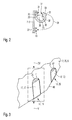
- FIG. 3 shows the in Fig. 1 With III designated section of a shell 2 of a water-conducting household appliance 1 according to a second embodiment in a schematic, spatial representation.
- the fastening parts 19, 29 of the closure elements 17, 18 are arranged on an underside 40 of the shell body 6 of the shell 2 and connected thereto, while the fastening parts 19, 29 of the closure elements 17, 18 in the basis of FIGS. 1 and 2 described first embodiment of the front side 25 of the shell body 6 of the shell 2 are arranged.
- the closure parts 20, 30 of the closure elements 17, 18 are inserted in this embodiment in the recesses 26, 27, leaving free spaces 41, 42 free.
- a user can engage with a fingertip or a fingernail in the space 41 and push the closure member 20 of the closure member 17 away from the front side 25 of the recess 26 and then press down towards the bottom 40.
- the open outlet 15 is in the Fig. 4 shown.
- the user can open the shutter member 18 by engaging in the clearance 42.
- an aid can also be used to open the closure elements 17, 18.
- the closure parts 20, 30, which are inserted into the recess 26, 27, close in the closed state of the outlets 15, 16 with the front side 25 from.
- Fig. 4 shows the in Fig. 3 With IV designated section of the shell 2 of the water-conducting household appliance 1 according to the second embodiment.
- the outlet 15 is shown when the opening 22 is released.
- the closure part 20 of the closure element 17 depends on the attached to the bottom 40 of the shell body 6 mounting member 19 before the outlet 15 down.
- the plug 21 is pressed with the sealing lip 23 in the opening 22 of the spout 15.
- the closure part 20 of the closure element 17 is then inserted again into the recess 26.
- Fig. 5 shows the in Fig. 3 with IV designated section of the shell 2 of the water-conducting household appliance 1 of the second embodiment of the V direction of view designated.
- the fastening part 19 of the closure element 17 is fastened to the underside 40.
- 40 rib-shaped projections 43, 44 are formed on the underside, to which the fastening part 19 is joined. Due to the rib-shaped projections 33, 44, the closure element 17 is reliably connected to the shell body 6 in the region of the fastening part 19. In this case, the rib-shaped projections 33, 44 engage through suitably configured passage openings in the fastening part 19.
- connection of the closure element 17 to its fastening part 19 with the underside 40 can also be made detachable, in order to enable cleaning or wear-related replacement of the closure element 17.
- the closure element 17 is bent around an edge 45 between the underside 40 and the front surface 4 of the shell body 6.
- the closure elements 17, 18 of the described embodiments have a color design, which differs from a color design of the shell body 6, in particular of a color design of the front side 25 and lifts. Specifically, an accent color for the closure elements 17, 18 can be selected.
- closure elements 17, 18 are connected to the shell body 6, so that they can not be lost. Furthermore, the closure elements 17, 18 are easy to serve. In addition, the closure elements 17, 18 may optionally be clipped in on itself, so that they do not interfere with the emptying.
Abstract
Description
Die Erfindung betrifft ein Hausgerät, insbesondere ein wasserführendes Haushaltsgerät, beispielsweise ein Wäschebehandlungsgerät zum Waschen und/oder Trocknen von Wäsche, und eine Schale für solch ein Hausgerät. Speziell betrifft die Erfindung das Gebiet der Waschmaschinen, Wäschetrockner und Waschtrockner.The invention relates to a domestic appliance, in particular a water-conducting domestic appliance, for example a laundry treatment appliance for washing and / or drying laundry, and a tray for such a domestic appliance. Specifically, the invention relates to the field of washing machines, tumble dryers and washer dryers.
Aus der
Die aus der
Aufgabe der Erfindung ist es, eine Schale, bei der die Bedienbarkeit erleichtert ist, und ein Hausgerät mit solch einer Schale zu schaffen. Speziell ist es eine Aufgabe der Erfindung, eine Schale, bei der eine bevorratete Flüssigkeit auf einfache Weise entnommen werden kann, und ein Hausgerät mit solch einer Schale zu schaffen.The object of the invention is to provide a shell in which the operability is facilitated, and a domestic appliance with such a shell. Specifically, it is an object of the invention to provide a tray in which a stored liquid can be easily removed, and a domestic appliance with such a tray.
Die Aufgabe wird durch eine erfindungsgemäße Schale und durch ein erfindungsgemäßes Hausgerät mit den Merkmalen des jeweiligen unabhängigen Patentanspruchs gelöst. Bevorzugte Ausgestaltungen der Schale und des Hausgeräts ergeben sich aus entsprechenden abhängigen Patentansprüchen sowie der nachfolgenden Beschreibung, wobei außerdem bevorzugten Ausgestaltungen der Schale bevorzugte Ausgestaltungen des Hausgeräts entsprechen und umgekehrt, und dies auch dann, wenn darauf hierin nicht explizit hingewiesen ist.The object is achieved by a shell according to the invention and by an inventive domestic appliance having the features of the respective independent patent claim. Preferred embodiments of the shell and the domestic appliance result from corresponding dependent claims and the following description, wherein also preferred embodiments of the shell correspond to preferred embodiments of the domestic appliance and vice versa, and this even if it is not explicitly stated herein.
Demnach hat die erfindungsgemäße Schale, welche insbesondere eine Einspülschale für ein wasserführendes Haushaltsgerät ist, einen Schalenkörper, wobei der Schalenkörper zumindest eine Kammer und einen der Kammer zugeordneten Auslauf aufweist, der mittels eines zumindest mittelbar mit dem Schalenkörper verbundenen, flexiblen Verschlusselements verschließbar ist.Accordingly, the shell according to the invention, which is in particular a Einspülschale for a water-conducting household appliance, a shell body, wherein the shell body has at least one chamber and a chamber associated with the outlet, the can be closed by means of a flexible closure element connected at least indirectly to the shell body.
Das erfindungsgemäße Hausgerät, insbesondere wasserführende Haushaltsgerät, ist demnach mit zumindest einem Gehäuseteil und einer erfindungsgemäßen Schale ausgestattet, wobei die Schale in das Gehäuseteil einbringbar ist.The household appliance according to the invention, in particular water-conducting household appliance, is accordingly equipped with at least one housing part and a shell according to the invention, wherein the shell can be introduced into the housing part.
Dabei besteht der Vorteil, dass eine Kammer der Schale in einfacher Weise entleert werden kann, wobei ein gezieltes Auffangen der Flüssigkeit ermöglicht wird, die aus der Kammer über den zugeordneten Auslauf ausläuft. Speziell besteht der Vorteil, dass die Schale vor einer Reinigung entleert werden kann, so dass das Reinigen der Schale erleichtert wird. Außerdem besteht insbesondere der Vorteil, dass der Inhalt der Kammer in einfacher Weise ausgetauscht werden kann. Dies ermöglicht insbesondere den Austausch eines verschmutzten oder aus anderen Gründen nicht mehr benötigten Wäschebehandlungsmittels oder dgl.There is the advantage that a chamber of the shell can be emptied in a simple manner, with a targeted collection of the liquid is made possible, which expires from the chamber via the associated outlet. Specifically, there is the advantage that the shell can be emptied before cleaning, so that the cleaning of the shell is facilitated. In addition, there is the particular advantage that the contents of the chamber can be easily replaced. This makes it possible, in particular, to exchange a soiled or otherwise no longer required laundry treatment agent or the like.
In vorteilhafter Weise ist das flexible Verschlusselement als Verschlusslasche ausgestaltet. Das flexible Verschlusselement ist zumindest abschnittsweise verbiegbar ausgestaltet, so dass es im Bereich des Auslaufs an den Auslauf gedrückt werden kann, um diesen zu verschließen, und von dem Auslauf entfernt werden kann, um den Auslauf zu öffnen, wobei das Verschlusselement mit dem Schalenkörper verbunden bleibt.Advantageously, the flexible closure element is designed as a closure flap. The flexible closure element is at least partially bendable designed so that it can be pressed in the region of the outlet to the outlet to close it, and can be removed from the outlet to open the outlet, the closure element remains connected to the shell body ,
Vorteilhaft ist es, dass ein Befestigungsteil des Verschlusselements mit dem Schalenkörper verbunden ist und dass ein Verschlussteil des Verschlusselements einen elastisch verformbaren Pfropfen aufweist, der zum Verschließen des der Kammer zugeordneten Auslaufs in eine Öffnung des Auslaufs einpressbar ist. Hierdurch ist eine einfache Bedienung möglich, um den Auslauf mittels des Verschlussteils des Verschlusselements zu öffnen und zu schließen. Insbesondere kann die Bedienung mit einer Hand ermöglicht werden, da der Verschlussteil dauerhaft dem Auslauf zugeordnet ist und zum Verschließen in einfacher Weise auf den Auslauf gedrückt werden kann, wodurch der elastisch verformbare Pfropfen des Verschlussteils des Verschlusselements den Auslauf verschließt.It is advantageous that a fastening part of the closure element is connected to the shell body and that a closure part of the closure element has an elastically deformable plug which can be pressed into an opening of the outlet for closing the outlet associated with the chamber. As a result, a simple operation is possible to open and close the outlet by means of the closure part of the closure element. In particular, the operation can be made with one hand, since the closure part is permanently associated with the outlet and can be pressed to close in a simple manner on the outlet, whereby the elastically deformable plug of the closure part of the closure element closes the outlet.
Dabei ist es ferner vorteilhaft, dass der elastisch verformbare Pfropfen eine ringförmige, elastisch verformbare Dichtlippe aufweist, um eine zuverlässige Abdichtung zu gewährleisten. Außerdem kann durch die ringförmige Dichtlippe ein zuverlässiger Sitz im Auslauf der Kammer erzielt werden.It is also advantageous that the elastically deformable plug has an annular, elastically deformable sealing lip to a reliable seal guarantee. In addition, a reliable seat in the outlet of the chamber can be achieved by the annular sealing lip.
Vorteilhaft ist es, dass der Befestigungsteil des Verschlusselements eine Raststelle aufweist, an der der Verschlussteil bei geöffnetem Auslauf einrastbar ist. Dabei ist es ferner vorteilhaft, dass die Raststelle des Befestigungsteils des Verschlusselements durch eine Ausnehmung gebildet ist, in die ein Vorsprung des Verschlussteils des Verschlusselements einrastbar ist, oder dass die Raststelle des Befestigungsteils des Verschlusselements durch einen Vorsprung gebildet ist, der in eine Ausnehmung des Verschlussteils des Verschlusselements einrastbar ist. Die Ausgestaltung der Ausnehmung ist dabei an die Ausgestaltung des Vorsprungs angepasst. Speziell kann eine zylinderförmige Ausnehmung vorgesehen sein, in die ein zylinderförmiger Vorsprung einrastbar ist. Hierbei kann an dem Vorsprung ein Einstich vorgesehen sein, um ein zuverlässiges Einrasten zu gewährleisten.It is advantageous that the fastening part of the closure element has a latching point, on which the closure part can be latched when the outlet is open. It is also advantageous that the latching point of the fastening part of the closure element is formed by a recess into which a projection of the closure part of the closure element can be latched, or that the latching point of the fastening part of the closure element is formed by a projection which is in a recess of the closure part the closure element can be latched. The configuration of the recess is adapted to the configuration of the projection. Specifically, a cylindrical recess may be provided, into which a cylindrical projection can be latched. Here, a puncture may be provided on the projection to ensure reliable engagement.
Der Befestigungsteil des Verschlusselements kann in vorteilhafter Weise an einer Vorderseite des Schalenkörpers oder an einer Unterseite des Schalenkörpers angeordnet sein. Hierdurch sind vorteilhafte Anordnungen des Verschlusselements gegeben, bei denen speziell eine vorteilhafte Lage des Verschlussteils des Verschlusselements vorgegeben ist. Hierdurch wird zum einen eine einfache Bedienung ermöglicht. Bei einer einschiebbaren und ausziehbaren Schale ist dabei eine Bedienung im eingeschobenen, teilweise ausgeschobenen und entfernten Zustand möglich. Hierbei ist es von besonderem Vorteil, dass der Auslauf an einer Vorderseite des Schalenkörpers vorgesehen ist.The fastening part of the closure element can be arranged in an advantageous manner on a front side of the shell body or on an underside of the shell body. As a result, advantageous arrangements of the closure element are given, in which an advantageous position of the closure part of the closure element is predetermined. As a result, on the one hand a simple operation is possible. With a retractable and extendable shell an operation in the inserted, partially ejected and removed state is possible. It is particularly advantageous that the outlet is provided on a front side of the shell body.
In vorteilhafter Weise ist an einer Außenseite des Schalenkörpers im Bereich des der Kammer zugeordneten Auslaufs eine Aussparung vorgesehen, in die das Verschlusselement zum Verschließen des Auslaufs einsetzbar ist. Dadurch kann das Verschlusselement bündig mit der Außenseite des Schalenkörpers abschließen. Dies gewährleistet auch einen gewissen Schutz vor einem versehentlichen Öffnen oder einer Abnutzung bzw. Beschädigung während der Lebensdauer der Schale.Advantageously, a recess is provided on an outer side of the shell body in the region of the outlet associated with the chamber, into which the closure element can be inserted for closing the outlet. As a result, the closure element can be flush with the outside of the shell body. This also ensures some protection against accidental opening or wear during the life of the shell.
Hierbei ist es ferner vorteilhaft, dass die Aussparung so ausgestaltet ist, dass in der Aussparung an der Außenseite des Schalenkörpers bei eingesetztem Verschlusselement, das den Auslauf verschließt, ein Freiraum freibleibt, um eine Entfernung des Verschlusselements aus der Aussparung zum Öffnen des Auslaufs zu ermöglichen. Beispielsweise kann durch den Freiraum eine Bedienperson mit einer Fingerkuppe oder einem Fingernagel das Verschlusselement aus der Aussparung an der Außenseite des Schalenkörpers herausheben.Here, it is also advantageous that the recess is designed so that in the recess on the outside of the shell body with inserted closure element which closes the outlet, a free space remains free to remove the To allow closure element from the recess for opening the spout. For example, an operator with a fingertip or a fingernail can lift the closure element out of the recess on the outside of the shell body through the clearance.
In vorteilhafter Weise unterscheidet sich eine farbliche Ausgestaltung des Verschlusselements von einer farblichen Ausgestaltung des Schalenkörpers. Speziell kann das Verschlusselement in einer Akzentfarbe ausgestaltet sein. Durch eine auffällige Ausgestaltung wird zum einen die Bedienung für einen Benutzer (Anwender) erleichtert, da er das Verschlusselement als ein von ihm betätigbares Verschlusselement erkennt. Zum anderen kann auf die besondere Funktion der Schale hingewiesen werden, wodurch sich ein Unterscheidungsmerkmal ergibt.Advantageously, a color configuration of the closure element differs from a color design of the shell body. Specifically, the closure element can be configured in an accent color. By a conspicuous configuration, on the one hand, the operation for a user (user) is facilitated, since he recognizes the closure element as an operable by him closure element. On the other hand can be pointed to the special function of the shell, resulting in a differentiator.
In vorteilhafter Weise ist eine mit dem Schalenkörper verbindbare Blende vorgesehen, wobei die Blende von dem Schalenkörper entfernbar ist und wobei das Verschlusselement von der Blende verdeckt ist, wenn die Blende mit dem Schalenkörper verbunden ist. Hierdurch kann eine formschöne Gestaltung der Schale erzielt werden, so dass insbesondere im eingesetzten oder eingeschobenen Zustand der Schale, in dem sich die Schale in einem Gehäuseteil eines Haushaltsgeräts befindet, eine formschöne Frontfläche des Hausgeräts verwirklichen lässt. Außerdem kann durch die Blende ein Schutz für den Verschluss des Auslaufs gebildet werden, da ein unbeabsichtigtes Lösen des Verschlusselements von dem Auslauf verhindert und gegebenenfalls ein vollständiges Verschließen des Auslaufs mittels des Verschlusselements und ein Fixieren des Verschlusselements erreicht werden kann.Advantageously, a connectable to the shell body panel is provided, wherein the panel is removable from the shell body and wherein the closure element is covered by the panel when the panel is connected to the shell body. In this way, a shapely design of the shell can be achieved, so that in particular in the inserted or inserted state of the shell, in which the shell is located in a housing part of a household appliance, a shapely front surface of the domestic appliance can be realized. In addition, a protection for the closure of the spout can be formed by the aperture, since unintentional release of the closure element from the spout prevented and optionally complete closure of the outlet by means of the closure member and a fixing of the closure element can be achieved.
Der Schalenkörper kann mehrere Kammern aufweisen, denen Ausläufe zugeordnet sind, die durch mit dem Schalenkörper verbundene, flexible Verschlusselemente verschließbar sind. Hierbei ergibt sich der Vorteil, dass die Verschlusselemente einzeln betätigt werden können, um gezielt einen Auslauf zu öffnen. Dadurch kann gezielt eine Kammer entleert werden. Hierdurch besteht auch die Möglichkeit, die in den Kammern enthaltenen Restbestände an Wäschebehandlungsmitteln oder dgl. getrennt voneinander aufzufangen, um diese nach einer Reinigung der Schale gegebenenfalls wieder in die Kammern einzufüllen. Außerdem kann eine versehentliche Falschbefüllung einer Kammer korrigiert werden.The shell body may have a plurality of chambers, which are associated with outlets, which are closed by connected to the shell body, flexible closure elements. This results in the advantage that the closure elements can be operated individually to selectively open an outlet. As a result, a chamber can be specifically emptied. As a result, it is also possible to separate the residues of laundry treatment agents or the like contained in the chambers separately from one another in order to optionally refill them into the chambers after a cleaning of the shell. In addition, an inadvertent incorrect filling of a chamber can be corrected.
Bevorzugte Ausführungsbeispiele der Erfindung sind in der nachfolgenden Beschreibung anhand der beigefügten Zeichnungen, in denen sich entsprechende Elemente mit übereinstimmenden Bezugszeichen sind, näher erläutert. Es zeigen:
-
Fig.1 1 ein Hausgerät mit einer Schale in einer auszugsweisen, schematischen, räumlichen Darstellung entsprechend einem ersten Ausführungsbeispiel; -
Fig. 2 einen auszugsweisen Schnitt durch die inFig. 1 dargestellte Schale des Hausgeräts entlang der mit II bezeichneten Schnittlinie; -
Fig. 3 den inFig. 1 mit III bezeichneten Ausschnitt einer Schale eines Hausgeräts entsprechend einem zweiten Ausführungsbeispiel in einer auszugsweisen, schematischen, räumlichen Darstellung; -
Fig. 4 den inFig. 3 mit IV bezeichneten Ausschnitt der Schale des Hausgeräts des zweiten Ausführungsbeispiels in einem Zustand, in dem ein Auslauf geöffnet ist, und -
Fig. 5 den inFig. 3 mit IV bezeichneten Ausschnitt der Schale des Hausgeräts des zweiten Ausführungsbeispiels aus der mit V bezeichneten Blickrichtung.
-
Fig.1 1 a domestic appliance with a shell in an excerpt, schematic, spatial representation according to a first embodiment; -
Fig. 2 an excerpted section through the inFig. 1 illustrated shell of the household appliance along the section line designated II; -
Fig. 3 the inFig. 1 with III designated section of a shell of a household appliance according to a second embodiment in a partial, schematic, spatial representation; -
Fig. 4 the inFig. 3 with IV designated section of the shell of the domestic appliance of the second embodiment in a state in which an outlet is open, and -
Fig. 5 the inFig. 3 with IV designated section of the shell of the domestic appliance of the second embodiment of the V direction of view designated.
Das wasserführende Haushaltsgerät 1 weist ein Gehäuseteil 3 auf. An dem Gehäuseteil 3 ist eine Frontfläche 4 vorgesehen. Das Gehäuseteil 3 weist eine durch einen Freiraum gebildete Aufnahme 5 auf, die zum Aufnehmen der Schale 2 dient. Die Schale 2 kann dabei in die Aufnahme 5 eingeschoben werden. Allerdings ist auch eine Ausgestaltung möglich, bei der die Schale 2 in eine Aufnahme 5 eingesetzt wird. Somit kann die Schale 2 in das Gehäuseteil 3 eingebracht werden.The water-conducting household appliance 1 has a
Die Schale 2 weist einen Schalenkörper 6 und eine Blende 7 auf. Die Blende 7 ist auf geeignete Weise mit dem Schalenkörper 6 verbindbar, wobei ein Benutzer die Verbindung lösen kann. Dadurch kann ein Benutzer die Blende 7 von dem Schalenkörper 6 abnehmen. Die Blende 7 ist als Griffschale ausgestaltet, wobei ein Eingriff 8 an der Blende 7 vorgesehen ist. An dem Eingriff 8 kann ein Benutzer den Schalenkörper 6 mit der Blende 7 aus der Aufnahme 5 ziehen. Hierbei kann der Benutzer die Schale 2 teilweise aus dem Gehäuseteil 3 ziehen und dann die Blende 7 demontieren, wie es in der
Die Schale 2 weist in diesem Ausführungsbeispiel Kammern 9, 10 auf, wobei Einfüllöffnungen für die Kammer 9, 10 durch Kunststoffdeckel 11, 12 abgedeckt sind. Die Kammern 9, 10 ermöglichen die Bevorratung von zwei verschiedenen Wäschebehandlungsmitteln. Im Allgemeinen können in den Kammern 9, 10 Flüssigkeiten bevorratet werden, wobei der Begriff Flüssigkeit allgemein zu verstehen ist. Beispielsweise können derartige Flüssigkeiten auch relativ viskos ausgebildet sein und/oder Partikel, insbesondere pulverförmige Waschmittel oder dgl., enthalten.The shell 2 has in this
Ferner ist eine weitere Kammer 13 vorgesehen, die nicht als Vorratskammer dient, sondern im Betrieb des wasserführenden Haushaltsgeräts 1 durchspült und dabei vollständig geleert wird.Furthermore, a
Die Kammern 9, 10 können so genutzt werden, dass Wäschebehandlungsmittel für mehrere Programmdurchläufe bevorratet sind. Nach einigen Programmdurchläufen ist dann eine Auffüllung einer oder beider Kammern 9, 10 erforderlich. In der Regel wird aber zumindest in einer der Kammern 9, 10 immer eine gewisse Menge an Wäschebehandlungsmittel bevorratet sein. Wenn ein Benutzer nun nach einer größeren Anzahl von Programmdurchläufen die Schale 2 reinigen möchte, dann besteht das Problem, dass beim Ausleeren der Schale 2 die noch bevorrateten Mengen an Wäschebehandlungsmitteln verloren gehen. Ein getrenntes Auffangen der in den Kammern 9, 10 noch verbleibenden Restmengen ist nicht oder nur mit großem Aufwand möglich.The
Außerdem kann ein Benutzer versehentlich das falsche Wäschebehandlungsmittel in eine der Kammern 9, 10 einfüllen. In diesem Fall steht der Benutzer ebenfalls vor dem Problem, wie er das versehentlich eingefüllte Wäschebehandlungsmittel aus der Schale 2 entfernt. Ein gezieltes Auffangen des versehentlich eingefüllten Wäschebehandlungsmittels ist hier ebenfalls vorteilhaft.In addition, a user may inadvertently fill the wrong laundry treating agent in one of the
Zur Lösung dieser Probleme weist das wasserführende Hausgerät 1 des ersten Ausführungsbeispiels Ausläufe 15, 16 auf, wobei der Auslauf 16 in der
Außerdem sind flexible Verschlusselemente 17, 18 vorgesehen, mit denen die Ausläufe 15, 16 verschließbar sind. In der
Die Verschlusselemente 17, 18 sind in diesem Ausführungsbeispiel unmittelbar, d.h. direkt, mit dem Schalenkörper 6 verbunden. Die Verschlusselemente 17, 18 können aber auch mittelbar mit dem Schalenkörper 6 verbunden sein, beispielsweise mittels geeigneter Befestigungsmittel.The
Die Verschlusselemente 17, 18 sind als Verschlusslaschen ausgestaltet. Hierbei sind die Verschlusselemente 17, 18 zumindest abschnittsweise biegbar, wie es anhand des Verschlusselements 17 in der
Das Verschlusselement 17 weist einen Befestigungsteil 19 und einen Verschlussteil 20 auf. Dabei ist das Verschlusselement 17 an seinem Befestigungsteil 19 mit dem Schalenkörper 6 verbunden. Der Verschlussteil 20 des Verschlusselements 17 weist einen elastisch verformbaren Pfropfen 21 auf, der in eine Öffnung 22 des Auslaufs 15 einpressbar ist. Hierbei ist an dem Pfropfen 21 des Verschlussteils 20 eine ringförmige, elastisch verformbare Dichtlippe 23 ausgeformt, wodurch eine Abdichtung des Auslaufs 15 weiter verbessert ist und ein gewisser Widerstand erzeugt wird, der einem Herausdrücken oder Herausziehen des Pfropfens 21 aus der Öffnung 22 des Auslaufs 15 entgegenwirkt.The
In diesem Ausführungsbeispiel sind die Ausläufe 15, 16 an einer Vorderseite 25 des Schalenkörpers 6 angeordnet. Hierdurch ist ein komfortabler Zugriff auf die Verschlusselemente 17, 18 zum Öffnen der Ausläufe 15, 16 bzw. zum Verschließen der Ausläufe 15, 16 möglich.In this embodiment, the
An der Vorderseite 25 sind Aussparungen 26, 27 vorgesehen, in die die Verschlusselemente 17, 18 einsetzbar sind. Beim Verschließen der Ausläufe 15, 16 schließen die Verschlusselemente 17, 18 dann bündig mit der Vorderseite 25 des Schalenkörpers 6 ab.On the
Der Befestigungsteil 19 des Verschlusselements 17 weist eine Raststelle 28 auf, an der der Verschlussteil 20 bei geöffnetem Auslauf 15 einrastbar ist. Dabei ist die Raststelle 28 in diesem Ausführungsbeispiel durch eine Ausnehmung gebildet, in die ein Vorsprung des Verschlussteils 20 des Verschlusselements 17 einrastbar ist, wie es in weiterem Detail auch anhand des Verschlusselements 18 beschrieben ist.The
Die Ausgestaltung des wasserführenden Haushaltsgeräts 1 ist im Folgenden auch mit Bezugnahme auf die
An dem Befestigungsteil 29 des Verschlusselements 18 ist eine Raststelle 34 vorgesehen, die durch eine Ausnehmung 35 in dem Befestigungsteil 29 gebildet ist. Die Ausnehmung 35 dient dabei zum Aufnehmen eines zylinderförmigen Vorsprungs 36 des Verschlussteils 30, der dem Pfropfen 31 abgewandt ist. Der Vorsprung 36 weist dabei eine Einschnürung 37 auf, um das Einrasten zu erleichtern. Die Ausnehmung 35 des Befestigungsteils 29 ist an die Ausgestaltung des Vorsprungs 36 des Verschlussteils 30 angepasst.On the
Zum Einrasten des Vorsprungs 36 des Verschlussteils 30 in die Ausnehmung 35 des Befestigungsteils 29 wird der Befestigungsteil 19 in Richtung auf die Ausnehmung 35 von einem Benutzer gepresst, wie es durch den Pfeil 38 veranschaulicht ist. Im eingerasteten Zustand ergibt sich der Vorteil, dass das Verschlusselement 18 das Entleeren der Kammer 10 nicht behindert.For engaging the
Zum Verschließen des Auslaufs 16 wird die Rastverbindung gelöst und der Verschlussteil 30 des Verschlusselements 18 gegen den Auslauf 16 gepresst, wie es durch den Pfeil 39 veranschaulicht ist. Die Ausgestaltung der Verschlusselemente 17, 18 hat den Vorteil, dass eine einhändige Bedienung möglich ist. Dadurch kann ein Benutzer mit der anderen Hand ein Gefäß oder dgl. unter den jeweiligen Auslauf 15, 16 halten, um die Flüssigkeit, insbesondere das Wäschebehandlungsmittel, aufzufangen.To close the
Entsprechend kann der Benutzer das Verschlusselement 18 durch Eingreifen in den Freiraum 42 öffnen. Zum Öffnen der Verschlusselemente 17, 18 kann jedoch auch ein Hilfsmittel dienen. Die Verschlussteile 20, 30, die in die Aussparung 26, 27 eingelegt sind, schließen im geschlossenen Zustand der Ausläufe 15, 16 mit der Vorderseite 25 ab.Accordingly, the user can open the
Die Verschlusselemente 17, 18 der beschriebenen Ausführungsbeispiele weisen eine farbliche Ausgestaltung auf, die sich von einer farblichen Ausgestaltung des Schalenkörpers 6, insbesondere von einer farblichen Ausgestaltung der Vorderseite 25, unterscheidet und abhebt. Speziell kann eine Akzentfarbe für die Verschlusselemente 17, 18 gewählt werden.The
Bei den zuvor im einzelnen beschriebenen Ausführungsbeispielen besteht der Vorteil, dass die Verschlusselemente 17, 18 mit dem Schalenkörper 6 verbunden sind, so dass diese nicht verloren gehen können. Ferner sind die Verschlusselemente 17, 18 leicht zu bedienen. Außerdem können die Verschlusselemente 17, 18 gegebenenfalls in sich selbst geclipst werden, so dass diese beim Entleeren nicht stören.In the embodiments described above in detail, there is the advantage that the
Die Erfindung ist nicht auf die beschriebenen Ausführungsbeispiele beschränkt.The invention is not limited to the described embodiments.
- 11
- Hausgerät (wasserführendes Haushaltsgerät)Domestic appliance (water-conducting household appliance)
- 22
- SchaleBowl
- 33
- Gehäuseteilhousing part
- 44
- Frontflächefront surface
- 55
- Aufnahmeadmission
- 66
- Schalenkörpershell body
- 77
- Blendecover
- 88th
- Eingriffintervention
- 9, 109, 10
- Kammerchamber
- 11, 1211, 12
- KunststoffdeckelPlastic lid
- 1313
- Kammerchamber
- 15, 1615, 16
- Auslaufoutlet
- 17, 1817, 18
- Verschlusselementclosure element
- 1919
- Befestigungsteilattachment portion
- 2020
- Verschlussteilclosing part
- 2121
- PfropfenGraft
- 2222
- Öffnungopening
- 2323
- Dichtlippesealing lip
- 2525
- Vorderseitefront
- 26,2726.27
- Aussparungrecess
- 2828
- Raststelleresting place
- 2929
- Befestigungsteilattachment portion
- 3030
- Verschlussteilclosing part
- 3131
- PfropfenGraft
- 3232
- Öffnungopening
- 3333
- Dichtlippesealing lip
- 3434
- Raststelleresting place
- 3535
- Ausnehmungrecess
- 3636
- Vorsprunghead Start
- 3737
- Einschnürungconstriction
- 38, 3938, 39
- Pfeilarrow
- 4040
- Unterseitebottom
- 41, 4241, 42
- Freiraumfree space
- 43, 4443, 44
- rippenförmiger Vorsprungrib-shaped projection
- 4545
- Kanteedge
Claims (15)
Priority Applications (1)
| Application Number | Priority Date | Filing Date | Title |
|---|---|---|---|
| PL10170369T PL2281939T3 (en) | 2009-08-03 | 2010-07-22 | Household device with dispenser |
Applications Claiming Priority (1)
| Application Number | Priority Date | Filing Date | Title |
|---|---|---|---|
| DE102009028187A DE102009028187A1 (en) | 2009-08-03 | 2009-08-03 | Domestic appliance with a bowl |
Publications (2)
| Publication Number | Publication Date |
|---|---|
| EP2281939A1 true EP2281939A1 (en) | 2011-02-09 |
| EP2281939B1 EP2281939B1 (en) | 2012-05-30 |
Family
ID=43334694
Family Applications (1)
| Application Number | Title | Priority Date | Filing Date |
|---|---|---|---|
| EP10170369A Active EP2281939B1 (en) | 2009-08-03 | 2010-07-22 | Household device with dispenser |
Country Status (3)
| Country | Link |
|---|---|
| EP (1) | EP2281939B1 (en) |
| DE (1) | DE102009028187A1 (en) |
| PL (1) | PL2281939T3 (en) |
Cited By (1)
| Publication number | Priority date | Publication date | Assignee | Title |
|---|---|---|---|---|
| US11718948B2 (en) | 2018-08-30 | 2023-08-08 | Electrolux Appliances Aktiebolag | Laundry treatment appliance with improved drawer |
Citations (7)
| Publication number | Priority date | Publication date | Assignee | Title |
|---|---|---|---|---|
| US3207373A (en) * | 1962-12-18 | 1965-09-21 | Bauknecht Gmbh G | Means for introducing a detergent into washing machines |
| DE3246127A1 (en) * | 1982-12-13 | 1984-06-14 | Bosch-Siemens Hausgeräte GmbH, 7000 Stuttgart | Appliance having devices for the storage, metering and addition of liquid washing and rinsing agents |
| DE19954706A1 (en) * | 1999-11-13 | 2001-05-23 | Aeg Hausgeraete Gmbh | Cleaning agent dispenser for dishwashers or washing machines has one or more bimetallic retaining clips which deform to release the agent at a predetermined temperature |
| EP1324428A2 (en) * | 2001-12-28 | 2003-07-02 | J.S.T. Mfg. Co., Ltd. | Connector with retainer members to be attached to a panel, method of attaching the connector to the panel, and method of coupling the connector with another connector |
| DE102004059137A1 (en) * | 2003-12-09 | 2005-07-14 | Elbi International S.P.A. | Device for the metered delivery of a liquid washing, rinsing or Nachspülsubstanz for a washing machine |
| EP1884584A2 (en) | 2006-07-31 | 2008-02-06 | Indesit Company S.p.A. | A washing machine, in particular a laundry washer, comprising a large capacity washing agents dispenser |
| DE102007052076B3 (en) * | 2007-10-31 | 2009-01-02 | BSH Bosch und Siemens Hausgeräte GmbH | Water-bearing household appliance i.e. washing machine, has lock with opening unit to open opening of wall based on predetermined filling level of liquid, and closing unit to close opening independent of filling level of liquid |
Family Cites Families (2)
| Publication number | Priority date | Publication date | Assignee | Title |
|---|---|---|---|---|
| DE19908801B4 (en) * | 1999-03-01 | 2010-04-15 | BSH Bosch und Siemens Hausgeräte GmbH | Condensate collector for tumble dryers |
| DE10259343B4 (en) * | 2002-12-18 | 2013-01-17 | BSH Bosch und Siemens Hausgeräte GmbH | Condensing tumble dryer and condensate collection vessel |
-
2009
- 2009-08-03 DE DE102009028187A patent/DE102009028187A1/en not_active Withdrawn
-
2010
- 2010-07-22 PL PL10170369T patent/PL2281939T3/en unknown
- 2010-07-22 EP EP10170369A patent/EP2281939B1/en active Active
Patent Citations (7)
| Publication number | Priority date | Publication date | Assignee | Title |
|---|---|---|---|---|
| US3207373A (en) * | 1962-12-18 | 1965-09-21 | Bauknecht Gmbh G | Means for introducing a detergent into washing machines |
| DE3246127A1 (en) * | 1982-12-13 | 1984-06-14 | Bosch-Siemens Hausgeräte GmbH, 7000 Stuttgart | Appliance having devices for the storage, metering and addition of liquid washing and rinsing agents |
| DE19954706A1 (en) * | 1999-11-13 | 2001-05-23 | Aeg Hausgeraete Gmbh | Cleaning agent dispenser for dishwashers or washing machines has one or more bimetallic retaining clips which deform to release the agent at a predetermined temperature |
| EP1324428A2 (en) * | 2001-12-28 | 2003-07-02 | J.S.T. Mfg. Co., Ltd. | Connector with retainer members to be attached to a panel, method of attaching the connector to the panel, and method of coupling the connector with another connector |
| DE102004059137A1 (en) * | 2003-12-09 | 2005-07-14 | Elbi International S.P.A. | Device for the metered delivery of a liquid washing, rinsing or Nachspülsubstanz for a washing machine |
| EP1884584A2 (en) | 2006-07-31 | 2008-02-06 | Indesit Company S.p.A. | A washing machine, in particular a laundry washer, comprising a large capacity washing agents dispenser |
| DE102007052076B3 (en) * | 2007-10-31 | 2009-01-02 | BSH Bosch und Siemens Hausgeräte GmbH | Water-bearing household appliance i.e. washing machine, has lock with opening unit to open opening of wall based on predetermined filling level of liquid, and closing unit to close opening independent of filling level of liquid |
Cited By (1)
| Publication number | Priority date | Publication date | Assignee | Title |
|---|---|---|---|---|
| US11718948B2 (en) | 2018-08-30 | 2023-08-08 | Electrolux Appliances Aktiebolag | Laundry treatment appliance with improved drawer |
Also Published As
| Publication number | Publication date |
|---|---|
| PL2281939T3 (en) | 2012-10-31 |
| EP2281939B1 (en) | 2012-05-30 |
| DE102009028187A1 (en) | 2011-02-10 |
Similar Documents
| Publication | Publication Date | Title |
|---|---|---|
| EP2281938B1 (en) | Water-guiding household device with a jacket | |
| EP2365120B1 (en) | Washing machine with a flushing box and insertable container | |
| DE102006057315B4 (en) | Detergent adding device of a washing machine | |
| EP2479335B1 (en) | Metering device for liquid and viscous dispensing agent for a washing machine and washing machine | |
| DE102016118334B3 (en) | Washing machine | |
| EP3180984B1 (en) | Cooking device | |
| DE60205658T2 (en) | DETERGENT DISPENSER FOR A HOUSEHOLD WASHING MACHINE, IN PARTICULAR A DISHWASHING MACHINE | |
| EP2110606A2 (en) | Commercial cooking device, in particular hot air steamer | |
| EP1861536B1 (en) | Detergent dispensing unit | |
| EP2281939B1 (en) | Household device with dispenser | |
| DE102010002853B4 (en) | Tank for a household appliance for preparing food and household appliance with such a tank | |
| EP2881510B1 (en) | Washing machine with storage containers for detergents | |
| DE102009029446B4 (en) | Water-bearing household appliance | |
| EP2462273A1 (en) | Water-bearing household appliance having a shell | |
| DE19921441B4 (en) | Household appliance, in particular washing machine, washer-dryer or dishwasher | |
| EP3305160A1 (en) | Storage container for assembly in a metering device of a cleaning device | |
| EP2937458A1 (en) | Laundry machine with a device for the addition of liquid washing and/or care products | |
| EP1980336B1 (en) | High pressure cleaning device | |
| DE102007041603B4 (en) | Dosing device and reservoir for liquid additive for a washing machine or dishwasher | |
| DE102015207345B4 (en) | Laundry care device with a detergent container | |
| DE1710562A1 (en) | Clip trap for a laundry treatment device equipped with a drain pump | |
| DE112017006241T5 (en) | Washing machine | |
| EP0982426A1 (en) | Detergent dispenser for washing machine | |
| WO2007131854A1 (en) | Washing machine comprising an emergency drain hose, and a method for draining said type of washing machine | |
| EP2465996B1 (en) | Water-transporting household device with a treatment agent compartment |
Legal Events
| Date | Code | Title | Description |
|---|---|---|---|
| PUAI | Public reference made under article 153(3) epc to a published international application that has entered the european phase |
Free format text: ORIGINAL CODE: 0009012 |
|
| AK | Designated contracting states |
Kind code of ref document: A1 Designated state(s): AL AT BE BG CH CY CZ DE DK EE ES FI FR GB GR HR HU IE IS IT LI LT LU LV MC MK MT NL NO PL PT RO SE SI SK SM TR |
|
| AX | Request for extension of the european patent |
Extension state: BA ME RS |
|
| 17P | Request for examination filed |
Effective date: 20110809 |
|
| GRAP | Despatch of communication of intention to grant a patent |
Free format text: ORIGINAL CODE: EPIDOSNIGR1 |
|
| RIC1 | Information provided on ipc code assigned before grant |
Ipc: D06F 39/02 20060101AFI20111222BHEP |
|
| RTI1 | Title (correction) |
Free format text: HOUSEHOLD DEVICE WITH DISPENSER |
|
| GRAS | Grant fee paid |
Free format text: ORIGINAL CODE: EPIDOSNIGR3 |
|
| GRAA | (expected) grant |
Free format text: ORIGINAL CODE: 0009210 |
|
| AK | Designated contracting states |
Kind code of ref document: B1 Designated state(s): AL AT BE BG CH CY CZ DE DK EE ES FI FR GB GR HR HU IE IS IT LI LT LU LV MC MK MT NL NO PL PT RO SE SI SK SM TR |
|
| REG | Reference to a national code |
Ref country code: GB Ref legal event code: FG4D Free format text: NOT ENGLISH |
|
| REG | Reference to a national code |
Ref country code: CH Ref legal event code: EP |
|
| REG | Reference to a national code |
Ref country code: AT Ref legal event code: REF Ref document number: 560133 Country of ref document: AT Kind code of ref document: T Effective date: 20120615 |
|
| REG | Reference to a national code |
Ref country code: IE Ref legal event code: FG4D Free format text: LANGUAGE OF EP DOCUMENT: GERMAN |
|
| REG | Reference to a national code |
Ref country code: DE Ref legal event code: R096 Ref document number: 502010000822 Country of ref document: DE Effective date: 20120802 |
|
| REG | Reference to a national code |
Ref country code: NL Ref legal event code: VDEP Effective date: 20120530 |
|
| REG | Reference to a national code |
Ref country code: LT Ref legal event code: MG4D Effective date: 20120509 |
|
| PG25 | Lapsed in a contracting state [announced via postgrant information from national office to epo] |
Ref country code: CY Free format text: LAPSE BECAUSE OF FAILURE TO SUBMIT A TRANSLATION OF THE DESCRIPTION OR TO PAY THE FEE WITHIN THE PRESCRIBED TIME-LIMIT Effective date: 20120530 Ref country code: LT Free format text: LAPSE BECAUSE OF FAILURE TO SUBMIT A TRANSLATION OF THE DESCRIPTION OR TO PAY THE FEE WITHIN THE PRESCRIBED TIME-LIMIT Effective date: 20120530 Ref country code: IS Free format text: LAPSE BECAUSE OF FAILURE TO SUBMIT A TRANSLATION OF THE DESCRIPTION OR TO PAY THE FEE WITHIN THE PRESCRIBED TIME-LIMIT Effective date: 20120930 Ref country code: FI Free format text: LAPSE BECAUSE OF FAILURE TO SUBMIT A TRANSLATION OF THE DESCRIPTION OR TO PAY THE FEE WITHIN THE PRESCRIBED TIME-LIMIT Effective date: 20120530 Ref country code: NO Free format text: LAPSE BECAUSE OF FAILURE TO SUBMIT A TRANSLATION OF THE DESCRIPTION OR TO PAY THE FEE WITHIN THE PRESCRIBED TIME-LIMIT Effective date: 20120830 Ref country code: SE Free format text: LAPSE BECAUSE OF FAILURE TO SUBMIT A TRANSLATION OF THE DESCRIPTION OR TO PAY THE FEE WITHIN THE PRESCRIBED TIME-LIMIT Effective date: 20120530 |
|
| REG | Reference to a national code |
Ref country code: PL Ref legal event code: T3 |
|
| PG25 | Lapsed in a contracting state [announced via postgrant information from national office to epo] |
Ref country code: SI Free format text: LAPSE BECAUSE OF FAILURE TO SUBMIT A TRANSLATION OF THE DESCRIPTION OR TO PAY THE FEE WITHIN THE PRESCRIBED TIME-LIMIT Effective date: 20120530 Ref country code: LV Free format text: LAPSE BECAUSE OF FAILURE TO SUBMIT A TRANSLATION OF THE DESCRIPTION OR TO PAY THE FEE WITHIN THE PRESCRIBED TIME-LIMIT Effective date: 20120530 Ref country code: GR Free format text: LAPSE BECAUSE OF FAILURE TO SUBMIT A TRANSLATION OF THE DESCRIPTION OR TO PAY THE FEE WITHIN THE PRESCRIBED TIME-LIMIT Effective date: 20120831 Ref country code: HR Free format text: LAPSE BECAUSE OF FAILURE TO SUBMIT A TRANSLATION OF THE DESCRIPTION OR TO PAY THE FEE WITHIN THE PRESCRIBED TIME-LIMIT Effective date: 20120530 |
|
| BERE | Be: lapsed |
Owner name: BSH BOSCH UND SIEMENS HAUSGERATE G.M.B.H. Effective date: 20120731 |
|
| PG25 | Lapsed in a contracting state [announced via postgrant information from national office to epo] |
Ref country code: SK Free format text: LAPSE BECAUSE OF FAILURE TO SUBMIT A TRANSLATION OF THE DESCRIPTION OR TO PAY THE FEE WITHIN THE PRESCRIBED TIME-LIMIT Effective date: 20120530 Ref country code: RO Free format text: LAPSE BECAUSE OF FAILURE TO SUBMIT A TRANSLATION OF THE DESCRIPTION OR TO PAY THE FEE WITHIN THE PRESCRIBED TIME-LIMIT Effective date: 20120530 Ref country code: CZ Free format text: LAPSE BECAUSE OF FAILURE TO SUBMIT A TRANSLATION OF THE DESCRIPTION OR TO PAY THE FEE WITHIN THE PRESCRIBED TIME-LIMIT Effective date: 20120530 Ref country code: NL Free format text: LAPSE BECAUSE OF FAILURE TO SUBMIT A TRANSLATION OF THE DESCRIPTION OR TO PAY THE FEE WITHIN THE PRESCRIBED TIME-LIMIT Effective date: 20120530 Ref country code: EE Free format text: LAPSE BECAUSE OF FAILURE TO SUBMIT A TRANSLATION OF THE DESCRIPTION OR TO PAY THE FEE WITHIN THE PRESCRIBED TIME-LIMIT Effective date: 20120530 Ref country code: DK Free format text: LAPSE BECAUSE OF FAILURE TO SUBMIT A TRANSLATION OF THE DESCRIPTION OR TO PAY THE FEE WITHIN THE PRESCRIBED TIME-LIMIT Effective date: 20120530 |
|
| PG25 | Lapsed in a contracting state [announced via postgrant information from national office to epo] |
Ref country code: MC Free format text: LAPSE BECAUSE OF NON-PAYMENT OF DUE FEES Effective date: 20120731 Ref country code: MK Free format text: LAPSE BECAUSE OF FAILURE TO SUBMIT A TRANSLATION OF THE DESCRIPTION OR TO PAY THE FEE WITHIN THE PRESCRIBED TIME-LIMIT Effective date: 20120530 Ref country code: PT Free format text: LAPSE BECAUSE OF FAILURE TO SUBMIT A TRANSLATION OF THE DESCRIPTION OR TO PAY THE FEE WITHIN THE PRESCRIBED TIME-LIMIT Effective date: 20121001 |
|
| PLBE | No opposition filed within time limit |
Free format text: ORIGINAL CODE: 0009261 |
|
| STAA | Information on the status of an ep patent application or granted ep patent |
Free format text: STATUS: NO OPPOSITION FILED WITHIN TIME LIMIT |
|
| REG | Reference to a national code |
Ref country code: FR Ref legal event code: ST Effective date: 20130329 |
|
| PG25 | Lapsed in a contracting state [announced via postgrant information from national office to epo] |
Ref country code: ES Free format text: LAPSE BECAUSE OF FAILURE TO SUBMIT A TRANSLATION OF THE DESCRIPTION OR TO PAY THE FEE WITHIN THE PRESCRIBED TIME-LIMIT Effective date: 20120910 Ref country code: FR Free format text: LAPSE BECAUSE OF NON-PAYMENT OF DUE FEES Effective date: 20120731 |
|
| 26N | No opposition filed |
Effective date: 20130301 |
|
| REG | Reference to a national code |
Ref country code: IE Ref legal event code: MM4A |
|
| PG25 | Lapsed in a contracting state [announced via postgrant information from national office to epo] |
Ref country code: BE Free format text: LAPSE BECAUSE OF NON-PAYMENT OF DUE FEES Effective date: 20120731 |
|
| REG | Reference to a national code |
Ref country code: DE Ref legal event code: R097 Ref document number: 502010000822 Country of ref document: DE Effective date: 20130301 |
|
| PG25 | Lapsed in a contracting state [announced via postgrant information from national office to epo] |
Ref country code: BG Free format text: LAPSE BECAUSE OF FAILURE TO SUBMIT A TRANSLATION OF THE DESCRIPTION OR TO PAY THE FEE WITHIN THE PRESCRIBED TIME-LIMIT Effective date: 20120830 Ref country code: MT Free format text: LAPSE BECAUSE OF FAILURE TO SUBMIT A TRANSLATION OF THE DESCRIPTION OR TO PAY THE FEE WITHIN THE PRESCRIBED TIME-LIMIT Effective date: 20120530 Ref country code: IE Free format text: LAPSE BECAUSE OF NON-PAYMENT OF DUE FEES Effective date: 20120722 |
|
| PG25 | Lapsed in a contracting state [announced via postgrant information from national office to epo] |
Ref country code: AL Free format text: LAPSE BECAUSE OF FAILURE TO SUBMIT A TRANSLATION OF THE DESCRIPTION OR TO PAY THE FEE WITHIN THE PRESCRIBED TIME-LIMIT Effective date: 20120530 |
|
| PG25 | Lapsed in a contracting state [announced via postgrant information from national office to epo] |
Ref country code: SM Free format text: LAPSE BECAUSE OF FAILURE TO SUBMIT A TRANSLATION OF THE DESCRIPTION OR TO PAY THE FEE WITHIN THE PRESCRIBED TIME-LIMIT Effective date: 20120530 Ref country code: LU Free format text: LAPSE BECAUSE OF NON-PAYMENT OF DUE FEES Effective date: 20120722 |
|
| PG25 | Lapsed in a contracting state [announced via postgrant information from national office to epo] |
Ref country code: HU Free format text: LAPSE BECAUSE OF FAILURE TO SUBMIT A TRANSLATION OF THE DESCRIPTION OR TO PAY THE FEE WITHIN THE PRESCRIBED TIME-LIMIT Effective date: 20100722 |
|
| REG | Reference to a national code |
Ref country code: CH Ref legal event code: PL |
|
| GBPC | Gb: european patent ceased through non-payment of renewal fee |
Effective date: 20140722 |
|
| PG25 | Lapsed in a contracting state [announced via postgrant information from national office to epo] |
Ref country code: LI Free format text: LAPSE BECAUSE OF NON-PAYMENT OF DUE FEES Effective date: 20140731 Ref country code: CH Free format text: LAPSE BECAUSE OF NON-PAYMENT OF DUE FEES Effective date: 20140731 |
|
| REG | Reference to a national code |
Ref country code: DE Ref legal event code: R081 Ref document number: 502010000822 Country of ref document: DE Owner name: BSH HAUSGERAETE GMBH, DE Free format text: FORMER OWNER: BSH BOSCH UND SIEMENS HAUSGERAETE GMBH, 81739 MUENCHEN, DE Effective date: 20150409 |
|
| PG25 | Lapsed in a contracting state [announced via postgrant information from national office to epo] |
Ref country code: GB Free format text: LAPSE BECAUSE OF NON-PAYMENT OF DUE FEES Effective date: 20140722 |
|
| REG | Reference to a national code |
Ref country code: AT Ref legal event code: MM01 Ref document number: 560133 Country of ref document: AT Kind code of ref document: T Effective date: 20150722 |
|
| PG25 | Lapsed in a contracting state [announced via postgrant information from national office to epo] |
Ref country code: AT Free format text: LAPSE BECAUSE OF NON-PAYMENT OF DUE FEES Effective date: 20150722 |
|
| PGFP | Annual fee paid to national office [announced via postgrant information from national office to epo] |
Ref country code: GB Payment date: 20180719 Year of fee payment: 17 |
|
| REG | Reference to a national code |
Ref country code: DE Ref legal event code: R084 Ref document number: 502010000822 Country of ref document: DE |
|
| PG25 | Lapsed in a contracting state [announced via postgrant information from national office to epo] |
Ref country code: IT Free format text: LAPSE BECAUSE OF NON-PAYMENT OF DUE FEES Effective date: 20190722 |
|
| PGFP | Annual fee paid to national office [announced via postgrant information from national office to epo] |
Ref country code: TR Payment date: 20230720 Year of fee payment: 14 |
|
| PGFP | Annual fee paid to national office [announced via postgrant information from national office to epo] |
Ref country code: PL Payment date: 20230711 Year of fee payment: 14 Ref country code: DE Payment date: 20230731 Year of fee payment: 14 |