EP2110606A2 - Commercial cooking device, in particular hot air steamer - Google Patents
Commercial cooking device, in particular hot air steamer Download PDFInfo
- Publication number
- EP2110606A2 EP2110606A2 EP08017495A EP08017495A EP2110606A2 EP 2110606 A2 EP2110606 A2 EP 2110606A2 EP 08017495 A EP08017495 A EP 08017495A EP 08017495 A EP08017495 A EP 08017495A EP 2110606 A2 EP2110606 A2 EP 2110606A2
- Authority
- EP
- European Patent Office
- Prior art keywords
- cooking appliance
- appliance according
- cartridge
- cooking
- cleaning device
- Prior art date
- Legal status (The legal status is an assumption and is not a legal conclusion. Google has not performed a legal analysis and makes no representation as to the accuracy of the status listed.)
- Withdrawn
Links
Images


Classifications
-
- F—MECHANICAL ENGINEERING; LIGHTING; HEATING; WEAPONS; BLASTING
- F24—HEATING; RANGES; VENTILATING
- F24C—DOMESTIC STOVES OR RANGES ; DETAILS OF DOMESTIC STOVES OR RANGES, OF GENERAL APPLICATION
- F24C14/00—Stoves or ranges having self-cleaning provisions, e.g. continuous catalytic cleaning or electrostatic cleaning
- F24C14/005—Stoves or ranges having self-cleaning provisions, e.g. continuous catalytic cleaning or electrostatic cleaning using a cleaning liquid
Definitions
- the invention relates to a commercial cooking appliance, in particular a combi steamer, according to the preamble of claim 1.
- Such commercial cooking appliances are provided with cleaning devices, so that the cooking chamber and arranged in the cooking chamber components of dirt can be removed.
- the solids cleaner can not be metered exactly according to the degree of contamination and, moreover, the application of the solid cleaner can not be fully automatically realized or this can only be carried out with great effort, which brings with it the risk of incorrect operation.
- the main disadvantage of the use of liquid cleaners is an increased space requirement for the storage canisters, if from the storage canisters immediately the liquid cleaner is to be sucked into the cleaning system of the cooking appliance. If the cooking appliance has storage containers on the appliance side, it is, as already explained, necessary to transfer the liquid detergent from the storage canister into these containers, which entails the risk of splashing of the liquid detergent in the kitchen.
- the cleaning device of the cooking appliance comprises a nozzle arrangement which comprises a selectable depending on the cooking chamber size number of fixed nozzles which operate at elevated pressure, so that a detergent spray is produced, the fine droplets, preferably by air support with the help of the device side Fans, can wet all surfaces in the oven, which, in contrast to previously known rotating nozzles, which distribute the cleaner in large drops, results in a significantly better cleaning performance.
- a cartridge according to the invention or a perforation needle according to the invention is defined as a self-negotiable object.
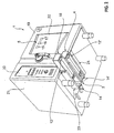
- Fig. 1 is an embodiment of a cooking appliance 1 according to the invention shown in front view that is designed in particular as a combi steamer.
- the cooking appliance has a cooking chamber 2, which is partially visible through a viewing window 22 of a cooking chamber 19.
- the cooking chamber door 19 may be attached in the usual way to the housing 21 of the cooking appliance 1 for opening and closing the cooking chamber 2.
- Fig. 1 further illustrates a visible through the viewing window 22 nozzle assembly 5, which has in the example case by the squares 15-17 symbolized nozzles.
- These nozzles 15-17 are part of a cleaning device 3 according to the invention of the cooking appliance 1, which will be described in more detail below.
- the nozzles 15-17 are fixedly mounted at suitable locations of the cooking chamber 2, so that they can wet all surfaces of the cooking chamber 2 in cooperation with the cleaning agent through the formation of a liquid cleaning spray.
- a storage container or a cartridge 18 for cleaning agent and a storage container or a cartridge 4 for rinse aid, preferably in the form of water, can be seen by the cleaning device 3, which in each case is assigned to the underside of the housing 21 Drawer guide 23 and 24 are arranged.
- the cartridges 18 and 4 can be inserted into the associated drawer slide 23 and 24 as interchangeable components, including the two cartridges engaging recesses or HandlingausEnglishept 12 and 12 ', which also in Fig. 2 are visible.
- the drawer guides are in the illustrated in the figures, particularly preferred embodiment with an in Fig. 1 each visible scaling 11 and 11 'provided.
- a simple level monitoring is possible in this way.
- Fig. 2 further clarifies that the cleaning device 3 the drawer guides 23 and 24 associated perforating 14 or 14 ', which are fixed to the device and each having Perforationsnadeln 14 a and 14 b, for example, from Fig. 3 can be seen.
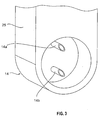
- the cartridge 4 As further from a synopsis of Fig. 4 and 5 shows, the cartridge 4, as well as the similarly constructed cartridge 18, a cuboid in the exemplary case cartridge housing 29, at one end of which the aforementioned engagement recess 12 and 12 'is arranged on the underside.
- the cartridge housing 29 further has an edge recess 13, one of Fig. 6 apparent stackable storage or transport packaging in an outer packaging 30 makes possible.
- the housing 29 At its engagement recess 12 or 12 'opposite end, the housing 29 on its underside a nozzle 28, the front side with a Fill opening 6 is provided.
- the filling opening 6 is covered by a perforable elastic membrane 7, which can be fixed by means of a cover 8 on the neck, preferably via a screw connection 10.
- the lid 8, in turn, has a through-passage 9, through which the perforation needles 14a and 14b of the perforation device 14 can pass.
- the perforation needles 14a and 14b are hollow and in fluid communication with suction conduits 26 and 27, respectively, as is understood Fig. 4 results.
- the suction lines 26 and 27 in turn lead to the nozzle assembly 5, wherein in each of the suction lines 26 and 27 an initially explained backflow preventer is arranged. Further, of course, a pumping arrangement is provided, which is not shown in the drawings, since it is not necessary for the explanation of the principles of the present invention.
- the cooking appliance 1 according to the invention is to be provided with a cartridge 18 for liquid cleaners and / or with a cartridge 4 for rinse aid, the corresponding cartridges are made of Fig. 6 apparent outer package 30 removed and according to Fig. 2 inserted into the respective drawer slide 23 and 24.
- Fig. 7 to 9 an alternative embodiment of a perforator 31 is shown. All parts with those of the embodiment according to the Fig. 1 to 6 match, are provided with the same reference numerals.
- Fig. 7 shows a sectional view of another embodiment of a perforation device 31 according to the invention.
- the perforation device 31 has a perforating needle 32, which is provided on its underside with a suction channel 33 and on its upper side with a supply air channel 34.
- the perforating needle 32 also has a fixing section 35, which is formed integrally with the perforating needle 32 at an end facing the connection port 38 and comprises two retaining projections 36, 37, which are provided with passage openings 39, 40 corresponding to the connection port 38 for forming a bayonet closure , In two circumferential grooves which are formed in the fixing section 35, two O-ring seals 41, 42 are inserted for fluid sealing between the replaceable perforating needle 32 and the connection port 38.
- connection port 38 has an intake manifold 43 for ambient air, which serves for pressure equalization, and an intake manifold 44 for supplying a liquid via the perforating needle 32.
- a sectional view of a cap 45 is shown, which has a receiving portion 47 formed therein a receiving channel 46 for the perforating needle 32 in a receiving portion 47.
- a receiving portion 47 formed therein a receiving channel 46 for the perforating needle 32 in a receiving portion 47.
- two projections 48, 49 are formed and at the opposite end of the cap 45, a handle portion 52 is formed.
- the cap 45 serves to transport safety and as an exchange tool for the perforating needle 32nd
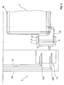
- Fig. 8 is a sectional view showing the reservoir 4; 18 and the cleaning device 3 with the perforation 31 shows, wherein the perforating needle 32 is inserted in the connection port 38.
- the perforating needle 32 passes through the lid. 8 into the passage recess 9 and perforates the membrane 7 mounted therein, which is designed here as a rubber stopper.
- Fig. 9 shows a greatly enlarged perspective view of the perforating needle 32 with the intake passage 33 formed therein and the supply air duct 34, and formed on the fixing portion 35 diametrically opposed retaining projections 36, 37.
- two end-side retaining recesses 50, 51 are formed in the fixing section 35, in which engage the projections 48, 49 of the cap 45 during assembly or replacement of the perforating needle 32.
- the perforating needle 32 can thereby be twisted or locked to form a bayonet closure with the connection port 38.
- the removal or disassembly of the perforating needle 32 is accordingly in the reverse direction.
- the in the Fig. 7 to 9 illustrated second embodiment of the perforation 31 has the advantage that the perforating needle 32 is interchangeable and with the help of the cap 50, which also serves as a transport lock, in the connection port 38 can be easily assembled and disassembled. Furthermore, the perforating needle 32 as a wear part, z. B. as an injection molded part, are made in one piece and thus cost.
Landscapes
- Chemical & Material Sciences (AREA)
- Engineering & Computer Science (AREA)
- Chemical Kinetics & Catalysis (AREA)
- Combustion & Propulsion (AREA)
- Mechanical Engineering (AREA)
- General Engineering & Computer Science (AREA)
- Cookers (AREA)
- Electric Ovens (AREA)
Abstract
Description
Die Erfindung betrifft ein gewerbliches Gargerät, insbesondere einen Heißluftdämpfer, gemäß dem Oberbegriff des Anspruchs 1.The invention relates to a commercial cooking appliance, in particular a combi steamer, according to the preamble of
Derartige gewerbliche Gargeräte sind mit Reinigungseinrichtungen versehen, damit der Garraum und die im Garraum angeordneten Komponenten von Verschmutzungen befreit werden können.Such commercial cooking appliances are provided with cleaning devices, so that the cooking chamber and arranged in the cooking chamber components of dirt can be removed.
Bekannt sind Feststoffreiniger als Tabletten oder Feststoffreiniger in einer Kartusche sowie Flüssigkeitsreiniger in größeren Tanks, die am oder in der Nähe des Gargerätes zur Entnahme des Flüssigkeitsreinigers aufgestellt werden müssen oder aus denen der Flüssigkeitsreiniger in gerätseitige Vorratsbehälter eingefüllt werden muss.Are known solid cleaners as tablets or solid cleaners in a cartridge and liquid cleaners in larger tanks that must be placed on or near the cooking appliance to remove the liquid cleaner or from which the liquid cleaner must be filled in device-side reservoir.
Die Nachteile von Feststoffreinigern sind vor allem darin zu sehen, dass diese hochkonzentriert sind und daher sehr aggressiv und gefährlich in der Handhabung sind. Ferner müssen sie in Wasser aufgelöst werden, was meist nicht rückstandsfrei erfolgen kann, so dass es zu Korrosionserscheinungen und/oder zusätzlich notwendig werdenden Ausspülungen kommen kann.The disadvantages of solids scavengers are mainly to be seen in the fact that they are highly concentrated and therefore very aggressive and dangerous to use. Furthermore, they must be dissolved in water, which usually can not be done without residue, so that it can lead to corrosion and / or additionally becoming necessary rinses.
Ferner ist der Feststoffreiniger nicht genau nach Verschmutzungsgrad dosierbar und überdies kann die Applizierung des Feststoffreinigers nicht voll automatisch realisiert bzw. dies nur mit nur sehr hohem Aufwand durchgeführt werden, was die Gefahr von Fehlbedienungen mit sich bringt.Furthermore, the solids cleaner can not be metered exactly according to the degree of contamination and, moreover, the application of the solid cleaner can not be fully automatically realized or this can only be carried out with great effort, which brings with it the risk of incorrect operation.
Der Hauptnachteil der Verwendung von Flüssigkeitsreinigern ist ein erhöhter Platzbedarf für die Vorratskanister, falls aus den Vorratskanistern unmittelbar der Flüssigkeitsreiniger in das Reinigungssystems des Gargerätes eingesaugt werden soll. Weist das Gargerät geräteseitige Vorratsbehälter auf, ist es, wie eingangs bereits erläutert, erforderlich, den Flüssigkeitsreiniger vom Vorratskanister in diese Behälter umzufüllen, was die Gefahr eines Verspritzens des Flüssigkeitsreinigers in der Küche mit sich bringt.The main disadvantage of the use of liquid cleaners is an increased space requirement for the storage canisters, if from the storage canisters immediately the liquid cleaner is to be sucked into the cleaning system of the cooking appliance. If the cooking appliance has storage containers on the appliance side, it is, as already explained, necessary to transfer the liquid detergent from the storage canister into these containers, which entails the risk of splashing of the liquid detergent in the kitchen.
Es ist daher Aufgabe der vorliegenden Erfindung, ein Gargerät der im Oberbegriff des Anspruches 1 angegebenen Art zu schaffen, dessen Reinigungseinrichtung auf einfache Art und Weise bedienbar ist und das eine sichere Handhabung ermöglicht.It is therefore an object of the present invention to provide a cooking appliance specified in the preamble of
Die Lösung dieser Aufgabe erfolgt durch die Merkmale des Anspruchs 1.The solution of this object is achieved by the features of
Mit der erfindungsgemäßen Lösung können insbesondere folgende Vorteile erreicht werden:
- In Verbindung mit einer vorzugsweise vorgesehenen Rückflussverhinderung in einer Saugleitung zwischen dem Vorratsbehälter und der Düsenanordnung der Reinigungseinrichtung ist es im Zusammenwirken mit der elastischen perforierbaren Membran im Deckel der Kartusche möglich, das Verschütten oder Versprühen des Flüssigreinigers in der Küche bzw. am Aufstellort des Gargerätes sicher zu verhindern.
- Da der Deckel der erfindungsgemäßen Kartusche abnehmbar ist, entsteht nach Entleerung der Kartusche kein Sondermüll, da die Kartusche vor der Entsorgung ausgespült werden kann, so dass sichergestellt ist, dass keine Reinigerrückstände in der leeren Kartusche verbleiben. Ferner ist es vom Prinzip her möglich, die erfindungsgemäße Kartusche nach der Entleerung wieder zu befüllen, mit einer neuen Membran zu versehen und danach mit Hilfe des Deckels wieder für einen erneuten Einsatz zu verschließen.
- Aufgrund der erfindungsgemäßen Anordnung ist das Reinigungsmittel sehr gut dosierbar.
- Die Kartusche mit dem Reinigungsmittel kann für mehr als eine Reinigung verwendet werden, so dass nicht bei jeder Reinigung ein Kartuschenwechsel erforderlich ist.
- Ferner ist es möglich, bei einer besonders bevorzugten Ausführungsform eine einfache Füllstandsüberwachung durchzuführen, da bei Verwendung eines durchsichtigen Materials für die Kartusche im Zusammenwirken mit einer Skalierung, die am Gargerät angebracht ist, der Füllstand auf einfache Art und Weise überprüfbar ist.
- Ferner ist es vorzugsweise möglich, die Kartusche in stapelbarer Form für eine einfache und platzsparende Verpackung und Versendung auszuführen.
- In conjunction with a preferably provided backflow prevention in a suction line between the reservoir and the nozzle assembly of the cleaning device, it is possible in cooperation with the elastic perforable membrane in the lid of the cartridge, the spilling or spraying of the liquid cleaner in the kitchen or at the installation of the cooking appliance safely prevent.
- Since the cover of the cartridge according to the invention is removable, created after emptying of the cartridge no hazardous waste, since the cartridge can be flushed out before disposal, so as to ensure that no detergent residues remain in the empty cartridge. Furthermore, it is in principle possible to refill the cartridge according to the invention after emptying, to provide it with a new membrane and then to close it again with the aid of the cover for reuse.
- Due to the arrangement according to the invention, the cleaning agent is very easy to dose.
- The detergent cartridge can be used for more than one cleaning, so you do not need to change cartridges every time you clean.
- Furthermore, it is possible to carry out a simple fill level monitoring in a particularly preferred embodiment, since the fill level can be checked in a simple manner when using a transparent material for the cartridge in cooperation with a scale which is mounted on the cooking appliance.
- Furthermore, it is preferably possible to carry out the cartridge in a stackable form for simple and space-saving packaging and shipping.
Die Unteransprüche 2-20 haben vorteilhafte Weiterbildungen des erfindungsgemäßen Gargeräts zum Inhalt.The dependent claims 2-20 have advantageous developments of the cooking appliance according to the invention to the content.
Bei einer besonders bevorzugten Ausführungsform weist die Reinigungseinrichtung des erfindungsgemäßen Gargeräts eine Düsenanordnung auf, die eine je nach Garraumgröße wählbare Anzahl von feststehenden Düsen umfasst, die mit erhöhtem Druck arbeiten, so dass ein Reinigungsmittelspray entsteht, dessen feine Tropfen, vorzugsweise durch Luftunterstützung mit Hilfe des geräteseitigen Lüfters, alle Flächen im Garraum benetzen kann, was im Gegensatz zu bisher bekannten rotierenden Düsen, welche den Reiniger in großen Tropfen verteilen, eine deutlich bessere Reinigungsleistung ergibt.In a particularly preferred embodiment, the cleaning device of the cooking appliance according to the invention comprises a nozzle arrangement which comprises a selectable depending on the cooking chamber size number of fixed nozzles which operate at elevated pressure, so that a detergent spray is produced, the fine droplets, preferably by air support with the help of the device side Fans, can wet all surfaces in the oven, which, in contrast to previously known rotating nozzles, which distribute the cleaner in large drops, results in a significantly better cleaning performance.
In den Ansprüchen 21, 22 und 23 ist eine erfindungsgemäße Kartusche bzw. eine erfindungsgemäße Perforationsnadel als selbstständig handelbares Objekt definiert.In
Weitere Einzelheiten, Vorteile und Merkmale der vorliegenden Erfindung ergeben sich aus nachfolgender Beschreibung von Ausführungsbeispielen anhand der Zeichnung.Further details, advantages and features of the present invention will become apparent from the following description of exemplary embodiments with reference to the drawing.
- Fig. 1Fig. 1
- eine schematisch leicht vereinfachte Darstellung eines erfindungsgemäßen Gargeräts in Vorderansicht,a schematically slightly simplified representation of a cooking appliance according to the invention in front view,
- Fig. 2Fig. 2
-
eine perspektivische Unteransicht des Gargeräts gemäß
Fig. 1 ,a perspective bottom view of the cooking appliance according toFig. 1 . - Fig. 3Fig. 3
- eine vergrößerte Darstellung einer Perforationseinrichtung des erfindungsgemäßen Gargeräts,an enlarged view of a perforation of the cooking appliance according to the invention,
- Fig. 4Fig. 4
- eine schematisch leicht vereinfachte vergrößerte Seitendarstellung der wesentlichen Komponenten einer Reinigungseinrichtung des erfindungsgemäßen Gargeräts,a schematically slightly simplified enlarged side view of the essential components of a cleaning device of the cooking appliance according to the invention,
- Fig. 5Fig. 5
- eine perspektivische Darstellung einer erfindungsgemäßen Kartusche,a perspective view of a cartridge according to the invention,
- Fig. 6Fig. 6
- eine perspektivische Darstellung einer in einer Umverpackung angeordneten Anzahl von erfindungsgemäßen Kartuschen, unda perspective view of a arranged in an outer packaging number of cartridges according to the invention, and
- Fig. 7 bis 9Fig. 7 to 9
- Darstellungen einer alternativen Ausführungsform einer Perforationseinrichtung.Representations of an alternative embodiment of a perforation device.
In
Das Gargerät weist einen Garraum 2 auf, der durch ein Sichtfenster 22 einer Garraumtür 19 teilweise sichtbar ist. Die Garraumtür 19 kann auf übliche Art und Weise am Gehäuse 21 des Gargeräts 1 zum Öffnen und Verschließen des Garraums 2 angebracht sein.The cooking appliance has a
Zur Vervollständigung der Beschreibung des erfindungsgemäßen Gargeräts 1 ist ferner auf ein Bedienpaneel 20 zu verweisen, das sämtliche Bedienelemente umfasst.In order to complete the description of the
Aufgrund der in
Wie vor allem die Darstellung der
Die Schubladenführungen sind bei der in den Figuren dargestellten, besonders bevorzugten Ausführungsform mit einer in
Wie sich ferner aus einer Zusammenschau der
An seinem der Eingriffsausnehmung 12 bzw. 12' gegenüberliegenden Ende weist das Gehäuse 29 an seiner Unterseite einen Stutzen 28 auf, der stirnseitig mit einer Einfüllöffnung 6 versehen ist. Wie sich insbesondere aus
Die Perforationsnadeln 14a und 14b sind hohl ausgebildet und stehen mit Saugleitungen 26 bzw. 27 in Strömungsverbindung, wie sich dies aus
Soll das erfindungsgemäße Gargerät 1 mit einer Kartusche 18 für Flüssigkeitsreiniger und/oder mit einer Kartusche 4 für Klarspüler versehen werden, werden die entsprechenden Kartuschen aus der aus
In den
Der Anschlussport 38 weist einen Ansaugstutzen 43 für Umgebungsluft, der zum Druckausgleich dient, und einen Ansaugstutzen 44 zur Zufuhr einer Flüssigkeit über die Perforiernadel 32 auf.The
Auf der linken Seite von
Die in den
In Ergänzung zur voranstehenden schriftlichen Offenbarung der Erfindung wird hiermit explizit auf deren zeichnerische Darstellung in den
- 11
- Gewerbliches Gargerät, insbesondere HeißluftdämpferCommercial cooking appliance, in particular combi steamer
- 22
- Garraumoven
- 33
- Reinigungseinrichtungcleaning device
- 44
- Vorratsbehälter/KartuscheReservoir / cartridge
- 55
- Düsenanordnungnozzle assembly
- 66
- Eintrittsöffnunginlet opening
- 77
- Membranmembrane
- 88th
- Deckelcover
- 99
- Durchtrittsausnehmungpassageway
- 1010
- Schraubverbindungscrew
- 11, 11'11, 11 '
- Skalierungscaling
- 12, 12'12, 12 '
- Eingriffsausnehmungengaging recess
- 1313
- Kantenaussparungedge recess
- 14, 14'14, 14 '
- Perforationseinrichtungperforation
- 14a, 14b14a, 14b
- Perforationsnadelnperforating
- 15-1715-17
- Düsenjet
- 1818
- KartuscheNorratsbehälterKartuscheNorratsbehälter
- 1919
- Garraumtüroven door
- 2020
- Bedienpaneelcontrol panel
- 2121
- Gehäusecasing
- 2222
- Sichtfensterwindow
- 23, 2423, 24
- Schubladenführungdrawer guide
- 2525
- Halterholder
- 26, 2726, 27
- Saugleitungsuction
- 2828
- StutzenSupport
- 2929
- Quaderförmiges KartuschengehäuseRectangular cartridge housing
- 3030
- Umverpackungoverpack
- 3131
- Perforationseinrichtungperforation
- 3232
- Perforiernadelpouncing
- 3333
- Ansaugkanalintake port
- 3434
- Zuluftkanalsupply air duct
- 3535
- Fixierabschnittfixing
- 36, 3736, 37
- Haltevorsprüngeretaining projections
- 3838
- Anschlussportconnection port
- 39, 4039, 40
- Durchtrittsausnehmungenpassageways
- 41, 4241, 42
- O-RingdichtungO-ring seal
- 4343
- Ansaugstutzen für UmgebungsluftIntake manifold for ambient air
- 4444
- Ansaugstutzen für FlüssigkeitIntake manifold for liquid
- 4545
- Kappecap
- 4646
- Aufnahmekanalreceiving channel
- 4747
- Aufnahmeabschnittreceiving portion
- 48, 4948, 49
- Vorsprüngeprojections
- 50, 5150, 51
- Halteausnehmungenholding recesses
- 5252
- Griffteilhandle part
Claims (23)
Applications Claiming Priority (1)
| Application Number | Priority Date | Filing Date | Title |
|---|---|---|---|
| DE102008019368 | 2008-04-17 |
Publications (2)
| Publication Number | Publication Date |
|---|---|
| EP2110606A2 true EP2110606A2 (en) | 2009-10-21 |
| EP2110606A3 EP2110606A3 (en) | 2011-10-05 |
Family
ID=40846129
Family Applications (1)
| Application Number | Title | Priority Date | Filing Date |
|---|---|---|---|
| EP08017495A Withdrawn EP2110606A3 (en) | 2008-04-17 | 2008-10-06 | Commercial cooking device, in particular hot air steamer |
Country Status (1)
| Country | Link |
|---|---|
| EP (1) | EP2110606A3 (en) |
Cited By (6)
| Publication number | Priority date | Publication date | Assignee | Title |
|---|---|---|---|---|
| DE102012203268A1 (en) * | 2012-02-29 | 2013-08-29 | Miwe Michael Wenz Gmbh | Cooking appliance with filling opening for filling cleaning fluid and method for filling a cooking appliance with cleaning fluid |
| WO2013088227A3 (en) * | 2011-12-13 | 2014-01-16 | Convotherm Elektrogerate Gmbh | Cleaning cartridge for a heating apparatus for cooking food and mechanism for opening cartridge |
| ITTV20130170A1 (en) * | 2013-10-17 | 2015-04-18 | Lainox Ali Spa | "OVEN FOR COLLECTIVE CATERING WITH A DETERGENT SUPPLY FOR THE COOKING CHAMBER WASHING SYSTEM" |
| DE102014008834A1 (en) * | 2014-06-20 | 2015-12-24 | Küppersbusch Großküchentechnik GmbH & Co. KG | Cooking and / or cooking appliance |
| DE102015105937A1 (en) * | 2015-04-17 | 2016-11-03 | Rational Aktiengesellschaft | Dosing container and cooking appliance |
| EP3702677A1 (en) * | 2019-02-26 | 2020-09-02 | Electrolux Professional S.p.A. | Cooking oven with steam generator |
Family Cites Families (3)
| Publication number | Priority date | Publication date | Assignee | Title |
|---|---|---|---|---|
| DE19961835C2 (en) * | 1999-12-21 | 2003-03-20 | Rational Ag | Method and device for automatic cooking appliance cleaning |
| WO2001051856A1 (en) * | 2000-01-10 | 2001-07-19 | Levens Group B.V. | Method and device for cleaning an oven |
| DE10060204B4 (en) * | 2000-11-28 | 2004-04-29 | Wiesheu Gmbh | Furnace cleaning system and method for furnace cleaning |
-
2008
- 2008-10-06 EP EP08017495A patent/EP2110606A3/en not_active Withdrawn
Non-Patent Citations (1)
| Title |
|---|
| None |
Cited By (10)
| Publication number | Priority date | Publication date | Assignee | Title |
|---|---|---|---|---|
| WO2013088227A3 (en) * | 2011-12-13 | 2014-01-16 | Convotherm Elektrogerate Gmbh | Cleaning cartridge for a heating apparatus for cooking food and mechanism for opening cartridge |
| CN104379998A (en) * | 2011-12-13 | 2015-02-25 | 康威瑟姆家电公司 | Cleaning cartridge for a heating apparatus for cooking food and mechanism for opening cartridge |
| DE102012203268A1 (en) * | 2012-02-29 | 2013-08-29 | Miwe Michael Wenz Gmbh | Cooking appliance with filling opening for filling cleaning fluid and method for filling a cooking appliance with cleaning fluid |
| EP2634492A1 (en) * | 2012-02-29 | 2013-09-04 | MIWE Michael Wenz GmbH | Cooking device with filling opening for cleaning liquid, system comprising container and cooking device and method for filling a cooking device with cleaning liquid |
| ITTV20130170A1 (en) * | 2013-10-17 | 2015-04-18 | Lainox Ali Spa | "OVEN FOR COLLECTIVE CATERING WITH A DETERGENT SUPPLY FOR THE COOKING CHAMBER WASHING SYSTEM" |
| WO2015056063A1 (en) * | 2013-10-17 | 2015-04-23 | Lainox Ali Spa | Oven for the foodservice industry with a device for feeding the detergent to the washing system of the cooking chamber |
| DE102014008834A1 (en) * | 2014-06-20 | 2015-12-24 | Küppersbusch Großküchentechnik GmbH & Co. KG | Cooking and / or cooking appliance |
| DE102014008834B4 (en) * | 2014-06-20 | 2016-09-22 | Küppersbusch Großküchentechnik GmbH & Co. KG | Cooking and / or cooking appliance |
| DE102015105937A1 (en) * | 2015-04-17 | 2016-11-03 | Rational Aktiengesellschaft | Dosing container and cooking appliance |
| EP3702677A1 (en) * | 2019-02-26 | 2020-09-02 | Electrolux Professional S.p.A. | Cooking oven with steam generator |
Also Published As
| Publication number | Publication date |
|---|---|
| EP2110606A3 (en) | 2011-10-05 |
Similar Documents
| Publication | Publication Date | Title |
|---|---|---|
| EP3331411B1 (en) | Cleaning agent container | |
| EP2237900B1 (en) | High-pressure cleaning device with a system for storing and dispensing liquid cleaning additive | |
| EP2110606A2 (en) | Commercial cooking device, in particular hot air steamer | |
| EP3021727A1 (en) | Portable hard-surface-cleaning appliance | |
| EP0711668A2 (en) | Ink refilling apparatus for ink jet cartridge | |
| DE202007019225U1 (en) | Apparatus for refilling an ink cartridge for an inkjet printer | |
| DE102013102263A1 (en) | Wet cleaning device, in particular window cleaning device | |
| WO2000012403A1 (en) | Device for emptying containers filled with liquids | |
| EP0064949A1 (en) | Container closure for a tapping unit | |
| EP3097829B1 (en) | Holding device, beverage machine with a holding device and method for reversibly fixing a cartridge in such a holding device | |
| EP1533125B1 (en) | Ink cartridge, ink cartridge unit and ink jet printhead | |
| DE202014000477U1 (en) | Removal device for liquids | |
| EP0504568B1 (en) | High pressure cleaning device | |
| EP2858864B1 (en) | Storage container, holder for a storage container, and vehicle treatment plant | |
| EP2942107A1 (en) | Coupling element | |
| DE202012008555U1 (en) | Cleaning device for cleaning spray guns | |
| EP2634492A1 (en) | Cooking device with filling opening for cleaning liquid, system comprising container and cooking device and method for filling a cooking device with cleaning liquid | |
| DE102016119427A1 (en) | Draining device for a domestic appliance and household appliance with a draining device | |
| DE8605007U1 (en) | Extraction device for oil | |
| EP2281939B1 (en) | Household device with dispenser | |
| EP3763266B1 (en) | Portable vacuum apparatus | |
| DE102009044539A1 (en) | System for filling a metering device of a dishwasher | |
| DE102015105937A1 (en) | Dosing container and cooking appliance | |
| DE102016108822A1 (en) | Detergent storage device and cooking appliance | |
| EP3265045B1 (en) | Sampling device for liquids |
Legal Events
| Date | Code | Title | Description |
|---|---|---|---|
| PUAI | Public reference made under article 153(3) epc to a published international application that has entered the european phase |
Free format text: ORIGINAL CODE: 0009012 |
|
| AK | Designated contracting states |
Kind code of ref document: A2 Designated state(s): AT BE BG CH CY CZ DE DK EE ES FI FR GB GR HR HU IE IS IT LI LT LU LV MC MT NL NO PL PT RO SE SI SK TR |
|
| AX | Request for extension of the european patent |
Extension state: AL BA MK RS |
|
| PUAL | Search report despatched |
Free format text: ORIGINAL CODE: 0009013 |
|
| AK | Designated contracting states |
Kind code of ref document: A3 Designated state(s): AT BE BG CH CY CZ DE DK EE ES FI FR GB GR HR HU IE IS IT LI LT LU LV MC MT NL NO PL PT RO SE SI SK TR |
|
| AX | Request for extension of the european patent |
Extension state: AL BA MK RS |
|
| RIC1 | Information provided on ipc code assigned before grant |
Ipc: F24C 14/00 20060101AFI20110830BHEP |
|
| 17P | Request for examination filed |
Effective date: 20120330 |
|
| AKX | Designation fees paid |
Designated state(s): CZ DE DK ES IT |
|
| STAA | Information on the status of an ep patent application or granted ep patent |
Free format text: STATUS: THE APPLICATION IS DEEMED TO BE WITHDRAWN |
|
| 18D | Application deemed to be withdrawn |
Effective date: 20130503 |