EP3097829B1 - Holding device, beverage machine with a holding device and method for reversibly fixing a cartridge in such a holding device - Google Patents
Holding device, beverage machine with a holding device and method for reversibly fixing a cartridge in such a holding device Download PDFInfo
- Publication number
- EP3097829B1 EP3097829B1 EP16167853.7A EP16167853A EP3097829B1 EP 3097829 B1 EP3097829 B1 EP 3097829B1 EP 16167853 A EP16167853 A EP 16167853A EP 3097829 B1 EP3097829 B1 EP 3097829B1
- Authority
- EP
- European Patent Office
- Prior art keywords
- cartridge
- receiving apparatus
- slide
- receiving device
- coupling device
- Prior art date
- Legal status (The legal status is an assumption and is not a legal conclusion. Google has not performed a legal analysis and makes no representation as to the accuracy of the status listed.)
- Active
Links
- 235000013361 beverage Nutrition 0.000 title claims description 17
- 238000000034 method Methods 0.000 title claims description 14
- XLYOFNOQVPJJNP-UHFFFAOYSA-N water Substances O XLYOFNOQVPJJNP-UHFFFAOYSA-N 0.000 claims description 33
- 230000008878 coupling Effects 0.000 claims description 27
- 238000010168 coupling process Methods 0.000 claims description 27
- 238000005859 coupling reaction Methods 0.000 claims description 27
- 238000003780 insertion Methods 0.000 claims description 12
- 230000037431 insertion Effects 0.000 claims description 12
- 238000012423 maintenance Methods 0.000 claims description 11
- 230000000295 complement effect Effects 0.000 claims description 4
- 238000001802 infusion Methods 0.000 claims description 3
- 230000000284 resting effect Effects 0.000 claims description 2
- 230000001419 dependent effect Effects 0.000 claims 4
- 239000003795 chemical substances by application Substances 0.000 description 12
- 238000013461 design Methods 0.000 description 6
- 238000007789 sealing Methods 0.000 description 6
- 239000013505 freshwater Substances 0.000 description 5
- 230000006872 improvement Effects 0.000 description 5
- 230000008569 process Effects 0.000 description 5
- 238000004519 manufacturing process Methods 0.000 description 4
- 238000011109 contamination Methods 0.000 description 3
- 238000011161 development Methods 0.000 description 3
- 230000018109 developmental process Effects 0.000 description 3
- 238000010586 diagram Methods 0.000 description 3
- 238000000605 extraction Methods 0.000 description 3
- 239000012530 fluid Substances 0.000 description 3
- 238000010438 heat treatment Methods 0.000 description 3
- 230000002776 aggregation Effects 0.000 description 2
- 238000004220 aggregation Methods 0.000 description 2
- 230000008901 benefit Effects 0.000 description 2
- 239000012459 cleaning agent Substances 0.000 description 2
- 230000000694 effects Effects 0.000 description 2
- 239000007788 liquid Substances 0.000 description 2
- 230000006911 nucleation Effects 0.000 description 2
- 238000010899 nucleation Methods 0.000 description 2
- 238000011022 operating instruction Methods 0.000 description 2
- 230000008439 repair process Effects 0.000 description 2
- 239000007787 solid Substances 0.000 description 2
- 230000004913 activation Effects 0.000 description 1
- 244000052616 bacterial pathogen Species 0.000 description 1
- 230000002308 calcification Effects 0.000 description 1
- 238000006243 chemical reaction Methods 0.000 description 1
- 238000010276 construction Methods 0.000 description 1
- 238000005520 cutting process Methods 0.000 description 1
- 239000000645 desinfectant Substances 0.000 description 1
- 238000006073 displacement reaction Methods 0.000 description 1
- BEFDCLMNVWHSGT-UHFFFAOYSA-N ethenylcyclopentane Chemical compound C=CC1CCCC1 BEFDCLMNVWHSGT-UHFFFAOYSA-N 0.000 description 1
- 230000036541 health Effects 0.000 description 1
- 238000007689 inspection Methods 0.000 description 1
- 230000014759 maintenance of location Effects 0.000 description 1
- 239000000463 material Substances 0.000 description 1
- 238000005259 measurement Methods 0.000 description 1
- 239000000203 mixture Substances 0.000 description 1
- 238000002360 preparation method Methods 0.000 description 1
- 229940075582 sorbic acid Drugs 0.000 description 1
- 235000010199 sorbic acid Nutrition 0.000 description 1
- 239000004334 sorbic acid Substances 0.000 description 1
- 239000003206 sterilizing agent Substances 0.000 description 1
- 238000003860 storage Methods 0.000 description 1
- 238000011144 upstream manufacturing Methods 0.000 description 1
- 239000002699 waste material Substances 0.000 description 1
Images

Classifications
-
- A—HUMAN NECESSITIES
- A47—FURNITURE; DOMESTIC ARTICLES OR APPLIANCES; COFFEE MILLS; SPICE MILLS; SUCTION CLEANERS IN GENERAL
- A47J—KITCHEN EQUIPMENT; COFFEE MILLS; SPICE MILLS; APPARATUS FOR MAKING BEVERAGES
- A47J31/00—Apparatus for making beverages
- A47J31/44—Parts or details or accessories of beverage-making apparatus
- A47J31/60—Cleaning devices
Definitions
- the invention relates to a receiving device into which a cartridge is inserted, which is necessary for the care of the flow line system of a drinks machine equipped with the cartridge and which contains a care product suitable for this purpose.
- a receiving device into which a cartridge is inserted, which is necessary for the care of the flow line system of a drinks machine equipped with the cartridge and which contains a care product suitable for this purpose.
- decalcification agents which are able to dissolve limescale due to a chemical reaction, to carry out regular maintenance processes on the flow line system and thereby free it from limescale deposits.
- a corresponding supply of decalcification agent is provided in suitable cartridges and removed from the cartridge when decalcification is to be carried out.
- the flow line system After a decalcification process, the flow line system is sometimes rinsed several times with fresh water and usually cleaned again in between before it can be used for its intended purpose again. Special cleaning agents are used to clean the flow line system.
- solutions are already known and in use in which suitable sterilizing agents are mixed with a decalcifying agent, so that the flow line system is also sterilized during decalcification.
- Other descaling agents also have a germ-reducing effect.
- Such an agent is, for example, sorbic acid.
- a cartridge is already known, the housing of which is closed in a liquid-tight manner by a cover which is designed for detachable connection with a corresponding receiving device.
- a dome-like connection pin is formed on the cover, which can be inserted into the receiving device and held therein by means of a clamp connection.
- a corresponding weight acts on this clamp connection, so that special requirements must be placed on the connection area between the receiving device and the connecting pin in terms of sealing in order to avoid leaks, i.e. the care product escaping from the cartridge or out the sealing area.
- a care product with a solid state of aggregation some of which is dissolved by the water introduced into the cartridge, so that in order to carry out a care process for the flow line system of the drinks machine equipped with the cartridge, a solution of part of the care product from the cartridge into the flow line system can be given.
- From the DE 10 2011 081 010 A1 also shows a receiving device for a disposable cartridge containing a descaling agent.
- This cartridge is connected to the drinks machine via a rigid, mechanical coupling device and in turn has an integrated pump, so that the construction of this cartridge is relatively complex.
- a new cartridge is required for each decalcification process and must be inserted into the drinks machine, with the empty cartridge having to be removed from the drinks machine again after the decalcification has been carried out once and then disposed of.
- the coupling area between the drinks machine and the cartridge is very complex, so that the embodiment disclosed in the document appears rather uneconomical from various points of view.
- the WO 2012/035247 A1 discloses a receiving device with a coupling device for a care medium cartridge for a flow line system in a drinks machine.
- the cartridge is attached to a slide with which the Cartridge, similar to a drawer, can be inserted into a receiving space in the device.
- a dip tube which extends from the inside of the container through the drawer into the inside of the beverage maker, serves as the coupling device.
- connection area between the cartridge and the receiving device harbors various problems. For example, when changing the cartridge, leaks can occur, which means that parts of the care product contained in the cartridge get into the Device interior of the cartridge receiving in a receiving device vending machine can get. This entails the risk of damage or at least severe contamination.
- the invention therefore addresses the problem of providing a receiving device with a coupling device for a cartridge, which has a maintenance agent for maintaining the flow line system present in a drinks machine, with a reliable seal between the cartridge and receiving device in particular being ensured.
- a beverage vending machine is to be specified which has such a receiving device and a method to be described with the aid of which the cartridge can be fixed in the receiving device.
- a receiving device with a coupling device for a cartridge the function of which is a portioned delivery of a care product for the care of the flow line system present in a drinks machine for preparing drinks, with the cartridge being able to be inserted into the coupling device in a liquid-tight manner with respect to the environment, was developed according to the invention such that in Recording device a cartridge positioning slide is arranged.
- the slider is of crucial importance. It establishes the connection between the receiving device and the cartridge to be inserted into it in a way that allows the weight of the cartridge to be absorbed. This can be achieved that the connection area between the cartridge and the receiving device is significantly relieved and the seal against the environment is simplified and improved. Consequently, the requirements for the seals to be used are significantly lower than is the case with known solutions.
- the component receiving the cartridge was designed as a slide, because a slide brings with it the advantage of being able to insert the cartridge into the receiving device and remove it from it again as often as desired.
- both disposable cartridges and reusable cartridges can be used more than once, which represents a significant simplification and improvement.
- the invention is therefore overall more economical and also more ecological than previously known designs.
- a first embodiment of the invention is that the cartridge has a water inlet connector and a care product discharge connector, which can be inserted into the coupling device with a precise fit, so that the cartridge can be coupled to the flow line system in a flow-conducting manner.
- connection between the cartridge and the flow line system of the drinks machine is made directly by inserting the cartridge into the receiving device or interrupted again when the cartridge is removed.
- the slide already mentioned at the beginning makes it possible to reliably avoid leaks that usually occur.
- a particularly simple and advantageous proposal consists in inserting the slide into the receiving device so that it can move along a corresponding sliding contour.
- a sliding surface is present on the slide for its mobility along the sliding contour.
- the main advantage of such an embodiment consists in the sliding contact of the slider with the receiving device, as a result of which the slider can be moved very smoothly and smoothly within the receiving device. It is therefore very easy to use, even for inexperienced users of a drinks machine equipped with it.
- the movability of the slide along the sliding contour of the receiving device can also consist of a sliding guide, so that additional transverse movements of the slide can be avoided and this is reliably guided within the receiving device.
- the receiving device is adapted accordingly and, for example, enables an end stop for the slide.
- the recording device has a one-sided has an open cartridge chamber with two equidistant and course-conform aligned guide slots, in each of which a corresponding slide shoe of the slide is guided.
- the guide slots are preferably designed as a self-contained contour in which the sliding shoes are accommodated and slidably guided. The slide shoes move between a front and a rear end stop, with the result that when the slide is pulled out of the receiving device, the cartridge can be easily inserted into the receiving device, in order to then close it in a suitable manner by inserting the slide into the receiving device fix.
- a very advantageous embodiment of the invention is that the slide has an adjustment surface that is formed on its side facing the cartridge and, when the slide is inserted into the receiving device, rests against a corresponding support surface of the cartridge that is oriented complementary to the adjustment surface.
- the slide also has the function of aligning a cartridge that may accidentally not be inserted exactly into the receiving device and thus ensuring that the sealing area between the cartridge and the receiving device functions reliably and seals. Consequently, the slider is helpful in terms of avoiding leakage.
- a special design variant of the adjustment surface can be seen in the fact that, viewed in cross section, it has an inclination to the horizontal and encloses an angle with the horizontal that is less than 90°.
- the adjusting surface is therefore designed as an inclined surface that exerts a resultant force on the supporting surface of the receiving device communicating with it, which very easily leads to the alignment of the cartridge within the receiving device when the slide is inserted into the receiving device.
- the cartridge is manufactured as a disposable item or as a reusable item, it generally has a cover element or a cover which is either detachably or integrally connected to the cartridge.
- a cover element or a cover which is either detachably or integrally connected to the cartridge.
- both the cover element and the cartridge as such are made of the same material and the water inlet connection and the care product discharge connection are designed as integral components of the cover element forming the upper end of the cartridge during production.
- This solution can be implemented in a particularly simple and cost-effective manner if the cartridge as a whole, ie including the cover element, is made of plastic.
- the cartridge has at least one web
- this can be used to insert the cartridge into the slide and to hold or fix it therein. Consequently, the web is introduced into a guide contour present in the slide. It is irrelevant whether the web is formed on the cartridge or on the cover element or is provided as a separate element on the cartridge.
- the web can be provided both on the cover element and in the area of the lateral surface of the cartridge and can have any desired cross-sectional geometry. The only important thing here is that it can be guided within the guide contour of the slide without any problems.
- the slide preferably accommodates the upper section of the cartridge, it is advantageous if there is at least a partial sliding guide in the area of the base of the cartridge, which slides on the inner lateral surface of the cartridge space.
- the consequence of this is that the cartridge is received in the slide in its cover-side area and is additionally guided within the receiving device in its bottom-side section. This significantly improves the reception and retention of the cartridge within the reception device. Lateral displacement of the cartridge can therefore be avoided with this simple measure and thus represents an additional improvement in sealing while avoiding leaks.
- Previously known cartridge designs are often relatively difficult to handle because the user is unsure how he can or should grasp such a cartridge and insert it into the receiving device. For this reason, an advantageous further development of the invention is that the cartridge has a handle on its side opposite the direction of insertion into the receiving device. With this relatively simple measure, the user of the vending machine is immediately and self-explanatory, without complex operating instructions, how the cartridge can be grasped in order to insert it into the receiving device or to remove it from the receiving device.
- a further improvement and simplification of the insertion of the cartridge into the receiving device or its removal from the receiving device can also be achieved if the cartridge has a symbol symbolizing the correct insertion movement of the cartridge into the receiving device on its side opposite the direction of insertion into the receiving device.
- this symbol can be an arrow, a double arrow, a curved arrow or an angled arrow, which symbolizes the insertion direction or the removal direction of the cartridge, depending on the design of the drinks machine or the design of the receiving device.
- the open water inlet connection or the open care product discharge connection poses a risk of the care product in the cartridge leaking out.
- the insertion direction in a detachable closure for the water inlet connection and the care product discharge connection is formed or arranged on the opposite side of the cartridge from the receiving device.
- the closure present in said section of the cartridge can, if necessary, be detached or separated from the cartridge and placed on the water inlet connection or the care product discharge connection, so that this simple measure means that no care product can escape from the cartridge.
- the closures are preferably manufactured as disposable items and can be formed directly on the outer surface of the cartridge, for example during production of the cartridge. Of course, it is also possible to deliver the closures with the cartridge so that they are available to the user of the drinks machine if required.
- the distance between the water inlet connector and the care product discharge connector of the cartridge is a fixed dimension, it is also possible, according to an embodiment of the solution described above, to form the closures as a unit. As such a unit, they can be detached from the cartridge if necessary and attached to the two aforementioned nozzles in just one operation.
- a disposable cartridge is understood to mean only a cartridge that is produced as a closed or encapsulated unit and is already filled with a care product. Once the care product has been completely used up, such disposable cartridges cannot generally be refilled with the care product. In the case of reusable items, however, refilling is possible at any time.
- the coupling device viewed in the direction of flow, has at least one one-way valve in front of the water inlet connection or after the care product discharge connection and/or the cartridge in Viewed in the direction of flow, in or after the water inlet connection or in front of or in the care product discharge connection each has at least one one-way valve.
- the valves mentioned seal off the parts of the flow line system in which fluid residues may be located.
- a drinks machine is characterized in that the drinks machine has a flow line system for the preparation of a mixed drink or an infusion drink.
- This flow line system has a receiving device with a cartridge in order to be able to carry out regular, preferably automatic maintenance of the flow line system with the help of the care agent contained therein. Consequently, the drinks machine is preferably a fully automatic machine.
- a fully automatic coffee machine is only mentioned here as an example.
- the flow line system of such a drinks machine includes various fluid lines that carry the media required for the production of the drinks. These can be liquid or gaseous media.
- a flow line system in a drinks machine also has various aggregates and/or devices. At this point, extraction devices are mentioned as an example, via which, for example, a drink can be extracted or water vapor can be released.
- One embodiment of the method according to the invention is that the slide is pushed into the receiving device until an adjustment surface on the slide has positioned the cartridge in its end position by resting against a support surface of the cartridge running complementary to the adjustment surface.
- the slide is consequently guided against the cartridge with a certain pressure, so that it adjusts its position in particular and thus fixes it at the same time.
- the adjustment surface and the support surface slide along each other until the cartridge is completely aligned in the receiving device.
- the one in the figure 1 The perspective view shown of a drinks machine 4 designed as a fully automatic coffee machine shows this in an oblique view from behind.
- the visible part of the vending machine 4 in figure 1 has a housing base 27, two opposite side surfaces 28 and a rear wall 29.
- the special feature of the example shown is that a removable cover 30 is integrated into the rear wall 29 to protect a receiving device 1 located behind it.
- the cover 30 In the lower area close to the housing base 27, the cover 30 has a gripping surface 31, which is used to loosen or remove the cover 30. The cover 30 is grasped at the gripping surface 31 and moved in the direction of the arrow A.
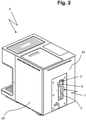
- FIG 2 From the figure 2 is a slightly different perspective on the vending machine 4 figure 1 out.
- the cover 30 was removed in the manner described above, so that a view into the receiving device 1 of the drinks machine 4 is now possible.
- the figure 2 remove a cartridge 3 inserted into a cartridge space 9 of the receiving device 1, the upper side of which is fixed in a coupling device 2.
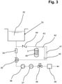
- the figure 3 shows a simplified circuit diagram of a flow line system of a drinks machine 4.
- the flow line system is supplied with fresh water 32 from a water source 33.
- the water source 33 shown is a water tank.
- the flow line system consists of two parts, with a first, water-carrying part used to prepare drinks and the other part, in this specific example, is branched off as a bypass from the first part of the flow line system and, if necessary, flow-carrying to the water-carrying part of the Flow line system can be connected.
- a one-way valve 44 and a multi-way valve 35 designed as a three-way valve are used to connect the bypass to or separate the bypass from the first part of the flow line system .
- the creation of a flow within the Flow line system and the required pressure build-up is realized by means of a pump 36.
- the part of the flow line system used to prepare the drinks has, in a manner known per se, a heating device 37 or a thermostat for heating the water and at least one extraction device 39, which is only indicated as a black box in the circuit diagram shown and which is, for example, can be a steam nozzle and/or a brewing unit for producing an infusion beverage.
- a further multi-way valve 38 which is connected upstream of the removal device 39 as viewed in the direction of flow, is also used for the selective activation of the removal device 39.
- the flow line system shown includes a flow rate meter 34 to accurately determine the amount of fresh water 32 required to prepare a beverage. Such a measuring device 34 can also be used to determine the number of drinks produced.
- the central element is the cartridge 3, which is supplied with fresh water 32 via a flow line 43, so that the care product 45 contained in the cartridge 3, which originally had a solid state of aggregation has, partially passes into a solution of the care agent, which is metered via the capillary line 42 to the designed as a bypass part of the flow line system is released when a care process is to be carried out.
- the capillary line 42 which opens into the bottom area of the cartridge 3 has a throttle point 40 or itself forms such a throttle point and is also connected to the flow line 43 at another point.
- the flow line 43 also has a throttle point 41, so that a defined back pressure is achieved within the flow line 43, which enables the cartridge 3 to be supplied with fresh water.
- the throttle points 41 and 40 each serve an exact dosage.
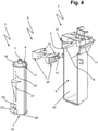
- the cartridge 3 has an elongated, approximately circular-cylindrical geometry.
- the lower part of the cartridge 3 is formed by a base 19 which has a sliding surface 26 on two opposite sides with a width which protrudes beyond the body of the cartridge.
- the cartridge 3 also has a cover element 16, in which a water inlet connector 7 and a care product discharge connector 6 are integrated.
- the water inlet connection 7 and the care products discharge connection 6 are when inserting the cartridge 3 in the Recording device 1 each coupled to a corresponding connection of the coupling device 2, so that thereby a flow-conducting connection to the flow line system of the drinks machine 4 can be made.
- the cartridge 3 shown also consists in the fact that it has a handle 21 on its side opposite the direction of insertion into the receiving device 1, which grips the cartridge 3 and inserts the cartridge 3 into the receiving device 1 and removes the cartridge 3 from the receiving device 1 considerably easier for the user.
- a symbol 22 in the form of a double arrow is applied to the cartridge 3 above the handle 21 . This symbol 22 serves to symbolize the direction in which the cartridge 3 is inserted or removed.
- the entire cartridge 3 is designed as a disposable cartridge, so that the base 19 and the cover element 16 as well as the closures 23, 24 are molded directly onto the cartridge 3 when it is manufactured.
- the cartridge 3 is inserted in its entirety into the receiving device 1 and fixed therein by means of the slide 5, a flow-conducting connection to the flow line system of the drinks machine 4 being established at the same time.
- a flow-conducting connection to the flow line system of the drinks machine 4 being established at the same time.
- the aforementioned web 17 of the cartridge 3 corresponds to a guide contour 18 of the slide 5 in such a way that the webs 17 formed on the cartridge 3 slide in this guide contour 18 and the slide 5 is pushed under the webs 17 of the cartridge 3 until the Cartridge 3 is fully accommodated in the receiving contour of the slide 5.
- the slider 5 is guided in a sliding manner via two sliding shoes 12 and 13 on its side in corresponding guide slots 10 and 11 of the receiving device 1 and via a sliding surface 25 on its underside in a sliding contour 8 of the cartridge space 9 of the receiving device 1.
- Through the contour of Guide slots 10, 11 are defined as end stops for the slide 5, between which movement of the slide 5 is possible.
- the slide 5 is first moved completely out of the cartridge space 9 until the sliding shoes 12, 13 come to rest on the outer end stops of the guide slots 10, 11.
- the cartridge 3 can now first be inserted into the cartridge chamber 9 with a horizontal movement and then moved vertically upwards in the direction of the symbol 22, so that the water inlet connection 7 and the care product removal connection 6 engage with the coupling device 2 and thus the already mentioned flow-conducting connection is made.
- the cartridge 3 would be fastened in the receiving device 1 in a conventional manner, for example by means of a clamp connection.
- the improvement according to the invention consists in the fact that the slide absorbs the weight of the cartridge 3 acting on the coupling device 2 and thus fixes the cartridge 3 in an improved manner within the receiving device 1 .
- the slide 5 is pushed into the receiving space 9 so that the sliding surfaces 18 slide along underneath the corresponding webs 17 of the cartridge 3 until the cartridge 3 is completely inserted into the the receiving contour provided for this purpose in the slide 5 bears against it.
- another special feature of the invention comes into play, which is that the adjustment surface 14, which is formed on the inner geometry of the receiving contour of the slide 5, comes to rest directly on a corresponding support surface 15 on the cover element 16 of the cartridge 3.
- the adjustment surface 14 has an inclination to the horizontal and is consequently, like the support surface 15, but in the opposite direction to the support surface 15, designed as an inclined surface.
- the entire cartridge 3 is aligned in an exact vertical position. This circumstance improves the sealing effect in the area of the coupling device 2 to a decisive extent.
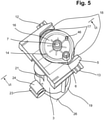
- a sensor 46 in the figure 5 can be seen better, interacts with a corresponding measured-value sensor and thus generates a signal that can be used to indicate the presence of the cartridge 3 in the receiving device 1.
- the sliding surface 26 already mentioned at the beginning is formed on the base 19 of the cartridge 3 . This serves to bear directly against the inner lateral surface 20 of the cartridge chamber 9 after the cartridge 3 has been inserted into the cartridge chamber 9 and thus to ensure that the cartridge 3 is guided at the bottom within the receiving device 1 .
- the perspective view of the cartridge 3 and the slider 5 in figure 5 shows the adjustment surface 14, which is directly on the corresponding, but in the figure 5 unspecified support surface 15 is present.
- the slide 5 has a receiving contour into which the cover element 16 of the cartridge 3 is inserted with a suitable fit.
- the webs 17 of the cover element 16 slide directly in the guide contour 18 provided for this purpose on the slide 5 .
- the measured value transmitter 46 corresponds to a suitable measured value recorder, which forwards the presence or absence of the cartridge 3 to a central control unit of the drinks machine 4 so that the signal determined can be used for a corresponding display in a suitable display device.
- the slide has sliding shoes 12, 13 on two opposite sides, which are slidably guided in the manner described above in corresponding guide slots 10, 11 in the cartridge space 9 of the receiving device 1.
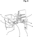
- the figure 6 shows the cutting line VI-VI figure 5 . From this it can be seen that the cartridge 3 in the area of the coupling device 2 is inserted with its water inlet socket 7 to fit into a corresponding connection of the receiving device 1 while at the same time forming a seal against the environment, for which purpose the water inlet socket 7 has seals in the form of simple O-rings on its outer circumference having. This simple type of seal is absolutely sufficient in the present case, since a reliable vertical alignment and fixation of the cartridge 3 in the receiving device 1 via the slide 5 is achieved by the invention.
- the adjustment surface 14 on the slider 5 and the supporting surface 15 corresponding thereto on the outer surface of the cover element 16 are clearly different from the representation in FIG figure 6 out. From the figure 6 In addition, the embodiment of the adjustment surface 14 and the support surface 15 as an inclined surface can be seen, with the progression of the inclines of the adjustment surface 14 and the support surface 15 being directed in opposite directions.
Landscapes
- Engineering & Computer Science (AREA)
- Food Science & Technology (AREA)
- Apparatus For Making Beverages (AREA)
Description
Die Erfindung betrifft eine Aufnahmevorrichtung, in die eine Kartusche eingesetzt wird, die für die Pflege des Strömungsleitungssystems eines mit der Kartusche ausgestatteten Getränkeautomaten erforderlich und in der ein hierfür geeignetes Pflegemittel enthalten ist. In Strömungsleitungssystemen, die auf Wasser basierende Fluide führen, besteht nämlich ein häufiges Problem darin, dass sich, über einen gewissen Zeitraum betrachtet, Teile des Strömungsleitungssystems sowie der darin enthaltenen Aggregate und Geräte zusetzen. Um dies zu verhindern, ist es bekannt, mit Entkalkungsmitteln, die auf Grund einer chemischen Reaktion in der Lage sind, Kalk zu lösen, regelmäßige Pflegevorgänge des Strömungsleitungssystems durchzuführen und dieses dadurch von den Kalkablagerungen zu befreien. Hierfür wird ein entsprechender Vorrat an Entkalkungsmittel in geeigneten Kartuschen bereitgestellt und bei einer durchzuführenden Entkalkung aus der Kartusche entnommen.The invention relates to a receiving device into which a cartridge is inserted, which is necessary for the care of the flow line system of a drinks machine equipped with the cartridge and which contains a care product suitable for this purpose. In flow line systems that carry water-based fluids, there is a frequent problem that, viewed over a certain period of time, parts of the flow line system and the aggregates and devices contained therein become clogged. In order to prevent this, it is known to use decalcification agents, which are able to dissolve limescale due to a chemical reaction, to carry out regular maintenance processes on the flow line system and thereby free it from limescale deposits. For this purpose, a corresponding supply of decalcification agent is provided in suitable cartridges and removed from the cartridge when decalcification is to be carried out.
Neben der hinlänglich bekannten Problematik der Verkalkung des Strömungsleitungssystems eines Getränkeautomaten wird häufig weniger beachtet, dass Wasser führende Strömungsleitungen in Abhängigkeit der Gegebenheiten auch eine Belastung mit Keimen aufweisen oder ausbilden können. Eine Keimbildung ist insbesondere zu beobachten, wenn die Flüssigkeit über eine gewisse Zeit in dem Strömungsleitungssystem steht und/oder wenn ein thermisches Umfeld existiert, das die Keimentwicklung begünstigt. Wird ein derartiges Strömungsleitungssystem nicht regelmäßig hinreichend gereinigt und nicht ebenso regelmäßig von Ablagerungen, wie dem zuvor beschriebenen Kalk, befreit, fördert dies auch eine Verkeimung, was insbesondere bei Getränkeautomaten problematisch ist. Die damit einhergehenden Gesundheitsgefahren sind nicht zu unterschätzen und rücken zunehmend in den Fokus der Betrachtung.In addition to the well-known problem of calcification of the flow line system of a drinks machine, less attention is often paid to the fact that water-carrying flow lines can also have or develop contamination with germs, depending on the circumstances. Nucleation can be observed in particular when the liquid stands in the flow line system for a certain period of time and/or when there is a thermal environment that promotes nucleation. If such a flow line system is not sufficiently cleaned regularly and is not freed from deposits as regularly as the limescale described above, this also encourages contamination, which is particularly problematic in the case of beverage dispensers. The associated health risks should not be underestimated and are increasingly becoming the focus of attention.
Nach einem Entkalkungsvorgang wird das Strömungsleitungssystem zum Teil mehrfach mit frischem Wasser gespült und in der Regel zwischendurch noch einmal zusätzlich gereinigt, bevor es wieder seinem eigentlichen Verwendungszweck dienen kann. Zur Reinigung des Strömungsleitungssystems kommen spezielle Reinigungsmittel zum Einsatz.After a decalcification process, the flow line system is sometimes rinsed several times with fresh water and usually cleaned again in between before it can be used for its intended purpose again. Special cleaning agents are used to clean the flow line system.
Teilweise sind bereits Lösungen bekannt und im Einsatz, bei denen einem Entkalkungsmittel geeignete Entkeimungsmittel beigemischt werden, so dass während der Entkalkung gleichzeitig auch eine Entkeimung des Strömungsleitungssystems erfolgt. Andere Entkalkungsmittel weisen auch eine Keime mindernde Wirkung auf. Ein derartiges Mittel ist beispielsweise die Sorbinsäure.In some cases, solutions are already known and in use in which suitable sterilizing agents are mixed with a decalcifying agent, so that the flow line system is also sterilized during decalcification. Other descaling agents also have a germ-reducing effect. Such an agent is, for example, sorbic acid.
Entkalkungsmittel, Entkeimungsmittel und Reinigungsmittel werden zur Vereinfachung nachfolgend einheitlich unter dem Begriff "Pflegemittel" zusammengefasst, wobei auch Mischungen der genannten Mittel unter diesen Begriff zu subsummieren sind.For reasons of simplification, descaling agents, disinfectants and cleaning agents are collectively referred to below under the term "care agents", with mixtures of the agents mentioned also being subsumed under this term.
Aus der
Aus der
Die
Der Verbindungsbereich zwischen Kartusche und Aufnahmevorrichtung birgt verschiedene Probleme in sich. So kann es beispielsweise beim Wechsel der Kartusche zu Leckagen kommen, was dazu führt, dass Teile des in der Kartusche enthaltenen Pflegemittels in das Geräteinnere des die Kartusche in einer Aufnahmevorrichtung aufnehmenden Getränkeautomaten gelangen können. Dies birgt die Gefahr von Schäden oder zumindest starken Verunreinigungen in sich.The connection area between the cartridge and the receiving device harbors various problems. For example, when changing the cartridge, leaks can occur, which means that parts of the care product contained in the cartridge get into the Device interior of the cartridge receiving in a receiving device vending machine can get. This entails the risk of damage or at least severe contamination.
Häufig ist auch zu beobachten, dass die Kartusche vom Anwender des Getränkeautomaten versehentlich nicht korrekt in den Getränkeautomaten eingesetzt wird, so dass es auch dadurch zu Leckagen kommen kann.It can also often be observed that the cartridge is accidentally not correctly inserted into the beverage dispenser by the user of the beverage dispenser, so that this can also lead to leaks.
Bislang sind keine befriedigenden Lösungen bekannt, die es ermöglichen, die Kartusche aus dem Getränkeautomaten zu entnehmen, wenn diese noch nicht vollständig entleert ist, um sie anschließend wieder in den Getränkeautomaten einsetzen zu können, ohne dass es zu Verlusten des Pflegemittels beziehungsweise zu Verlusten der Lösung des Pflegemittels kommt. Die Entnahme der noch teilweise befüllten Kartusche aus dem Getränkeautomaten kann beispielsweise dann erforderlich werden, wenn dieser zu Wartungs- und/oder Reparaturzwecken transportiert werden muss.So far, no satisfactory solutions are known that make it possible to remove the cartridge from the drinks machine when it is not yet completely empty, in order to then be able to use it again in the drinks machine without loss of the care product or loss of the solution of the care product. The removal of the still partially filled cartridge from the beverage dispenser can be necessary, for example, if it has to be transported for maintenance and/or repair purposes.
Der Erfindung stellt sich somit das Problem, eine Aufnahmevorrichtung mit einer Kupplungseinrichtung für eine Kartusche bereitzustellen, die ein Pflegemittel für die Pflege des in einem Getränkeautomaten vorhandenen Strömungsleitungssystems aufweist, wobei insbesondere eine zuverlässige Abdichtung zwischen Kartusche und Aufnahmevorrichtung gewährleistet sein sollte. Darüber hinaus ist ein Getränkeautomat anzugeben, der eine derartige Aufnahmevorrichtung aufweist und ein Verfahren zu beschreiben, mit dessen Hilfe die Kartusche in der Aufnahmevorrichtung fixierbar ist.The invention therefore addresses the problem of providing a receiving device with a coupling device for a cartridge, which has a maintenance agent for maintaining the flow line system present in a drinks machine, with a reliable seal between the cartridge and receiving device in particular being ensured. In addition, a beverage vending machine is to be specified which has such a receiving device and a method to be described with the aid of which the cartridge can be fixed in the receiving device.
Erfindungsgemäß wird dieses Problem durch eine Aufnahmevorrichtung mit den Merkmalen des Patentanspruches 1 sowie mit einem Getränkeautomaten nach Anspruch 16 und einemAccording to the invention, this problem is solved by a recording device with the features of
Verfahren gemäß dem Patentanspruch 17 gelöst.Method according to
Vorteilhafte Ausgestaltungen und Weiterbildungen der Erfindung ergeben sich aus den sich jeweils anschließenden Unteransprüchen.Advantageous refinements and developments of the invention result from the subclaims which follow in each case.
Eine Aufnahmevorrichtung mit einer Kupplungseinrichtung für eine Kartusche, deren Funktion eine portionierte Abgabe eines Pflegemittels zur Pflege des für die Getränkezubereitung in einem Getränkeautomaten vorhandenen Strömungsleitungssystems ist, wobei die Kartusche gegenüber der Umgebung flüssigkeitsdicht in die Kupplungseinrichtung einsetzbar ist, wurde erfindungsgemäß dahingehend weitergebildet, dass in der Aufnahmevorrichtung ein die Kartusche positionierender Schieber angeordnet ist.A receiving device with a coupling device for a cartridge, the function of which is a portioned delivery of a care product for the care of the flow line system present in a drinks machine for preparing drinks, with the cartridge being able to be inserted into the coupling device in a liquid-tight manner with respect to the environment, was developed according to the invention such that in Recording device a cartridge positioning slide is arranged.
Dem Schieber kommt dabei eine ganz maßgebliche Bedeutung zu. Er stellt die Verbindung zwischen der Aufnahmevorrichtung und der in diese einzusetzenden Kartusche in einer Weise her, die ein Abfangen der Gewichtskraft der Kartusche ermöglicht. Dadurch kann erreicht werden, dass der Verbindungsbereich zwischen Kartusche und Aufnahmevorrichtung ganz wesentlich entlastet und die Abdichtung gegenüber der Umgebung vereinfacht sowie verbessert wird. Folglich sind die Anforderungen an die einzusetzenden Dichtungen wesentlich geringer, als dies bei bekannten Lösungen der Fall ist. Das die Kartusche aufnehmende Bauteil wurde als Schieber ausgeführt, weil ein Schieber den Vorteil mit sich bringt, die Kartusche beliebig oft in die Aufnahmevorrichtung einsetzten und wieder aus dieser entnehmen zu können. Somit lassen sich mit der Erfindung sowohl Einweg-Kartuschen, als auch Mehrwegkartuschen mehrfacher verwenden, was eine wesentliche Vereinfachung und Verbesserung darstellt. Die Erfindung ist damit insgesamt ökonomischer und auch ökologischer, als bislang bekannte Ausführungen.The slider is of crucial importance. It establishes the connection between the receiving device and the cartridge to be inserted into it in a way that allows the weight of the cartridge to be absorbed. This can be achieved that the connection area between the cartridge and the receiving device is significantly relieved and the seal against the environment is simplified and improved. Consequently, the requirements for the seals to be used are significantly lower than is the case with known solutions. The component receiving the cartridge was designed as a slide, because a slide brings with it the advantage of being able to insert the cartridge into the receiving device and remove it from it again as often as desired. Thus, with the invention, both disposable cartridges and reusable cartridges can be used more than once, which represents a significant simplification and improvement. The invention is therefore overall more economical and also more ecological than previously known designs.
Eine erste Ausgestaltung der Erfindung geht dahin, dass die Kartusche einen Wasserzulaufstutzen und einen Pflegemittelabführstutzen aufweist, die passgenau in die Kupplungseinrichtung einsetzbar sind, sodass die Kartusche strömungsleitend mit dem Strömungsleitungssystem koppelbar ist.A first embodiment of the invention is that the cartridge has a water inlet connector and a care product discharge connector, which can be inserted into the coupling device with a precise fit, so that the cartridge can be coupled to the flow line system in a flow-conducting manner.
Anders ausgedrückt, wird die Verbindung zwischen der Kartusche und dem Strömungsleitungssystem des Getränkeautomaten unmittelbar durch das Einsetzen der Kartusche in die Aufnahmevorrichtung hergestellt beziehungsweise bei der Entnahme der Kartusche wieder unterbrochen. Der eingangs bereits erwähnte Schieber ermöglicht hierbei eine zuverlässige Vermeidung üblicherweise entstehender Leckagen.In other words, the connection between the cartridge and the flow line system of the drinks machine is made directly by inserting the cartridge into the receiving device or interrupted again when the cartridge is removed. The slide already mentioned at the beginning makes it possible to reliably avoid leaks that usually occur.
Ein besonders einfacher und vorteilhafter Vorschlag besteht darüber hinaus darin, den Schieber entlang einer korrespondierenden Gleitkontur bewegbar in die Aufnahmevorrichtung einzusetzen. Am Schieber ist für dessen Bewegbarkeit entlang der Gleitkontur eine Gleitfläche vorhanden. Der wesentliche Vorzug einer derartigen Ausführung besteht in dem Gleitkontakt des Schiebers mit der Aufnahmevorrichtung, wodurch der Schieber sehr gleichmäßig und leichtgängig innerhalb der Aufnahmevorrichtung bewegt werden kann. Seine Anwendung ist damit auch für ungeübte Nutzer eines damit ausgestatteten Getränkeautomaten sehr einfach. Die Bewegbarkeit des Schiebers entlang der Gleitkontur der Aufnahmevorrichtung kann auch in einer Gleitführung bestehen, sodass dadurch zusätzlich Querbewegungen des Schiebers vermieden werden können und dieser zuverlässig innerhalb der Aufnahmevorrichtung geführt ist.In addition, a particularly simple and advantageous proposal consists in inserting the slide into the receiving device so that it can move along a corresponding sliding contour. A sliding surface is present on the slide for its mobility along the sliding contour. The main advantage of such an embodiment consists in the sliding contact of the slider with the receiving device, as a result of which the slider can be moved very smoothly and smoothly within the receiving device. It is therefore very easy to use, even for inexperienced users of a drinks machine equipped with it. The movability of the slide along the sliding contour of the receiving device can also consist of a sliding guide, so that additional transverse movements of the slide can be avoided and this is reliably guided within the receiving device.
Zur Vermeidung des vollständigen Herauslösens des Schiebers aus der Aufnahmevorrichtung ist es hilfreich, wenn die Aufnahmevorrichtung hierfür entsprechend angepasst ist und beispielsweise einen Endanschlag des Schiebers ermöglicht. So geht ein weiterführender Vorschlag der Erfindung dahin, dass die Aufnahmevorrichtung einen einseitig offenen Kartuschenraum mit zwei äquidistant und verlaufskonform ausgerichteten Führungsschlitzen aufweist, in denen jeweils ein korrespondierender Gleitschuh des Schiebers geführt ist. Die Führungsschlitze werden hierbei bevorzugt als in sich geschlossene Kontur ausgeführt, in der die Gleitschuhe aufgenommen und gleitend geführt sind. Dabei bewegen sich die Gleitschuhe zwischen einem vorderen und einem hinteren Endanschlag, was zur Folge hat, dass bei aus der Aufnahmevorrichtung herausgezogenem Schieber die Kartusche problemlos in die Aufnahmevorrichtung eingeführt werden kann, um diese anschließend durch das Einführen des Schiebers in die Aufnahmevorrichtung in geeigneter Weise zu fixieren.In order to prevent the slide from being completely detached from the receiving device, it is helpful if the receiving device is adapted accordingly and, for example, enables an end stop for the slide. A further suggestion of the invention is that the recording device has a one-sided has an open cartridge chamber with two equidistant and course-conform aligned guide slots, in each of which a corresponding slide shoe of the slide is guided. The guide slots are preferably designed as a self-contained contour in which the sliding shoes are accommodated and slidably guided. The slide shoes move between a front and a rear end stop, with the result that when the slide is pulled out of the receiving device, the cartridge can be easily inserted into the receiving device, in order to then close it in a suitable manner by inserting the slide into the receiving device fix.
Da es immer wieder zu beobachten ist, dass trotz sorgfältigster Anweisungen in der Bedienungsanleitung eines Getränkeautomaten einzelne Anwender die Kartusche nicht korrekt in die Aufnahmevorrichtung einsetzen, sollte eine verbesserte Ausführung helfen, Fehler dieser Art von Anfang an zu vermeiden. Aus diesem Grund geht eine sehr vorteilhafte Ausgestaltung der Erfindung dahin, dass der Schieber eine Justierfläche aufweist, die auf seiner der Kartusche zugewandten Seite ausgebildet ist und bei in die Aufnahmevorrichtung eingesetztem Schieber an einer korrespondierenden und komplementär zu der Justierfläche ausgerichteten Stützfläche der Kartusche anliegt. Durch das einführen des Schiebers in die Aufnahmevorrichtung wird über die Justierfläche und die korrespondierende Stützfläche auf sehr einfache Weise eine Justierung beziehungsweise Ausrichtung der Kartusche innerhalb der Aufnahmevorrichtung erreicht. Mit anderen Worten hat der Schieber auch die Funktion, eine gegebenenfalls versehentlich nicht exakt in die Aufnahmevorrichtung eingesetzte Kartusche auszurichten und damit zu gewährleisten, dass der Dichtungsbereich zwischen Kartusche und Aufnahmevorrichtung zuverlässig funktioniert und abdichtet. Folgerichtig ist der Schieber hinsichtlich der Vermeidung von Leckagen hilfreich.Since it can be observed again and again that, despite the most careful instructions in the operating instructions for a drinks machine, individual users do not insert the cartridge correctly into the receiving device, an improved design should help to avoid mistakes of this type right from the start. For this reason, a very advantageous embodiment of the invention is that the slide has an adjustment surface that is formed on its side facing the cartridge and, when the slide is inserted into the receiving device, rests against a corresponding support surface of the cartridge that is oriented complementary to the adjustment surface. By inserting the slide into the receiving device, an adjustment or alignment of the cartridge within the receiving device is achieved in a very simple manner via the adjusting surface and the corresponding support surface. In other words, the slide also has the function of aligning a cartridge that may accidentally not be inserted exactly into the receiving device and thus ensuring that the sealing area between the cartridge and the receiving device functions reliably and seals. Consequently, the slider is helpful in terms of avoiding leakage.
Eine spezielle Ausgestaltungsvariante der Justierfläche ist darin zu sehen, dass diese im Querschnitt betrachtet eine Neigung zur Horizontalen aufweist und mit der Horizontalen einen Winkel einschließt, der weniger als 90° beträgt. Die Justierfläche wird demnach als eine Schrägfläche ausgeführt, die auf die mit ihr kommunizierende Stützfläche der Aufnahmevorrichtung eine resultierende Kraft ausübt, die auf sehr einfacher Weise beim Einführen des Schiebers in die Aufnahmevorrichtung zur Ausrichtung der Kartusche innerhalb der Aufnahmevorrichtung führt.A special design variant of the adjustment surface can be seen in the fact that, viewed in cross section, it has an inclination to the horizontal and encloses an angle with the horizontal that is less than 90°. The adjusting surface is therefore designed as an inclined surface that exerts a resultant force on the supporting surface of the receiving device communicating with it, which very easily leads to the alignment of the cartridge within the receiving device when the slide is inserted into the receiving device.
Unabhängig davon ob die Kartusche als Einwegartikel oder als Mehrwegartikel hergestellt wird, weist sie in der Regel ein Deckelelement beziehungsweise einen Deckel auf, der entweder lösbar oder stoffschlüssig mit der Kartusche verbunden ist. Zur Vereinfachung der Fertigung der Kartusche ist es von Vorteil, wenn sowohl das Deckelelement, als auch die Kartusche als solche aus dem gleichen Werkstoff hergestellt sind und während der Herstellung der Wasserzulaufstutzen und der Pflegemittelabführstutzen als integrale Bestandteile des den oberen Abschluss der Kartusche bildenden Deckelelementes ausgeführt werden. Besonders einfach und kostengünstig lässt sich diese Lösung umsetzen, wenn die Kartusche insgesamt, also einschließlich des Deckelelementes, aus Kunststoff hergestellt ist.Irrespective of whether the cartridge is manufactured as a disposable item or as a reusable item, it generally has a cover element or a cover which is either detachably or integrally connected to the cartridge. To simplify the When manufacturing the cartridge, it is advantageous if both the cover element and the cartridge as such are made of the same material and the water inlet connection and the care product discharge connection are designed as integral components of the cover element forming the upper end of the cartridge during production. This solution can be implemented in a particularly simple and cost-effective manner if the cartridge as a whole, ie including the cover element, is made of plastic.
Weist die Kartusche wenigstens einen Steg auf, so kann dieser dazu verwendet werden, die Kartusche in den Schieber einzusetzen und diese darin zu halten beziehungsweise zu fixieren. Folglich wird der Steg in eine in dem Schieber vorhandene Führungskontur eingeführt. Dabei ist es unerheblich, ob der Steg an der Kartusche oder am Deckelelement angeformt ist oder als separates Element an der Kartusche vorgesehen wird. Darüber hinaus kann der Steg sowohl am Deckelelement, als auch im Bereich der Mantelfläche der Kartusche vorgesehen werden und eine beliebige Querschnittsgeometrie aufweisen. Von Bedeutung ist hierbei lediglich, dass die Führung innerhalb der Führungskontur des Schiebers problemlos möglich ist.If the cartridge has at least one web, this can be used to insert the cartridge into the slide and to hold or fix it therein. Consequently, the web is introduced into a guide contour present in the slide. It is irrelevant whether the web is formed on the cartridge or on the cover element or is provided as a separate element on the cartridge. In addition, the web can be provided both on the cover element and in the area of the lateral surface of the cartridge and can have any desired cross-sectional geometry. The only important thing here is that it can be guided within the guide contour of the slide without any problems.
Da der Schieber bevorzugt den oberen Abschnitt der Kartusche aufnimmt, ist es von Vorteil, wenn im Bereich des Bodens der Kartusche zumindest partiell eine Gleitführung vorhanden ist, die an der Innenmantelfläche des Kartuschenraumes gleitet. Dies hat zur Folge, dass die Kartusche in ihrem deckelseitigen Bereich in dem Schieber aufgenommen und in ihrem bodenseitigen Abschnitt zusätzlich innerhalb der Aufnahmevorrichtung geführt ist. Dadurch wird die Aufnahme und der Halt der Kartusche innerhalb der Aufnahmevorrichtung wesentlich verbessert. Ein seitliches Ausweichen der Kartusche ist folglich mit dieser einfachen Maßnahme vermeidbar und stellt somit eine zusätzliche Verbesserung der Abdichtung unter Vermeidung von Leckagen dar.Since the slide preferably accommodates the upper section of the cartridge, it is advantageous if there is at least a partial sliding guide in the area of the base of the cartridge, which slides on the inner lateral surface of the cartridge space. The consequence of this is that the cartridge is received in the slide in its cover-side area and is additionally guided within the receiving device in its bottom-side section. This significantly improves the reception and retention of the cartridge within the reception device. Lateral displacement of the cartridge can therefore be avoided with this simple measure and thus represents an additional improvement in sealing while avoiding leaks.
Bisher bekannte Kartuschenausführungen sind häufig in der Handhabung verhältnismäßig schwierig, weil der Anwender unsicher ist, wie er eine derartige Kartusche erfassen und in die Aufnahmevorrichtung einsetzen kann oder soll. Aus diesem Grund geht eine vorteilhafte Weiterbildung der Erfindung dahin, dass die Kartusche auf ihrer der Einführrichtung in die Aufnahmevorrichtung gegenüberliegenden Seite einen Griff aufweist. Mit dieser verhältnismäßig einfachen Maßnahme wird dem Nutzer des Getränkeautomaten ohne eine aufwändige Bedienungsanleitung unmittelbar selbsterklärend klar, wie die Kartusche erfasst werden kann, um sie in die Aufnahmevorrichtung einzusetzen beziehungsweise sie aus der Aufnahmevorrichtung zu entnehmen.Previously known cartridge designs are often relatively difficult to handle because the user is unsure how he can or should grasp such a cartridge and insert it into the receiving device. For this reason, an advantageous further development of the invention is that the cartridge has a handle on its side opposite the direction of insertion into the receiving device. With this relatively simple measure, the user of the vending machine is immediately and self-explanatory, without complex operating instructions, how the cartridge can be grasped in order to insert it into the receiving device or to remove it from the receiving device.
Eine weitere Verbesserung und Erleichterung des Einsetzens der Kartusche in die Aufnahmevorrichtung beziehungsweise ihrer Entnahme aus der Aufnahmevorrichtung kann darüber hinaus dadurch erreicht werden, dass die Kartusche auf ihrer der Einführrichtung in die Aufnahmevorrichtung gegenüberliegenden Seite ein die korrekte Einführbewegung der Kartusche in die Aufnahmevorrichtung versinnbildlichendes Symbol aufweist. Dieses Symbol kann im einfachsten Fall ein Pfeil, ein Doppelpfeil, ein bogenförmiger Pfeil oder ein abgewinkelter Pfeil sein, der je nach Bauart des Getränkeautomaten beziehungsweise Ausführung der Aufnahmevorrichtung die Einführungsrichtung beziehungsweise die Entnahmerichtung der Kartusche symbolisiert.A further improvement and simplification of the insertion of the cartridge into the receiving device or its removal from the receiving device can also be achieved if the cartridge has a symbol symbolizing the correct insertion movement of the cartridge into the receiving device on its side opposite the direction of insertion into the receiving device. In the simplest case, this symbol can be an arrow, a double arrow, a curved arrow or an angled arrow, which symbolizes the insertion direction or the removal direction of the cartridge, depending on the design of the drinks machine or the design of the receiving device.
Wie eingangs bereits ausgeführt wurde, kann es beispielsweise für Wartungs- und/oder Reparaturarbeiten an dem Getränkeautomaten erforderlich werden, die Kartusche aus der Aufnahmevorrichtung zu entnehmen, auch, wenn diese noch nicht vollständig entleert ist. In einem solchen Fall stellt der geöffnete Wasserzulaufstutzen beziehungsweise der geöffnete Pflegemittelabführstutzen ein Risiko für das Auslaufen des in der Kartusche vorhandenen Pflegemittels dar. Für die Zeit der Aufbewahrung der geöffneten, jedoch nicht vollständig entleerten Kartusche ist es daher von Vorteil, wenn an der der Einführrichtung in die Aufnahmevorrichtung gegenüberliegenden Seite der Kartusche je ein ablösbarer Verschluss für den Wasserzulaufstutzen und den Pflegemittelabführstutzen angeformt oder angeordnet ist. Der in dem genannten Abschnitt der Kartusche vorhandene Verschluss kann im Bedarfsfall von der Kartusche abgelöst oder abgetrennt und auf den Wasserzulaufstutzen beziehungsweise den Pflegemittelabführstutzen aufgesetzt werden, so dass durch diese einfache Maßnahme kein Pflegemittel aus der Kartusche entweichen kann. Bevorzugt werden die Verschlüsse als Einwegartikel hergestellt und können beispielsweise bei der Produktion der Kartusche unmittelbar an der Außenoberfläche der Kartusche ausgebildet werden. Natürlich ist es ebenso möglich, die Verschlüsse mit der Kartusche auszuliefern, so dass sie dem Anwender des Getränkeautomaten im Bedarfsfall zur Verfügung stehen.As already explained at the outset, it may be necessary, for example for maintenance and/or repair work on the drinks machine, to remove the cartridge from the receiving device, even if it is not yet completely empty. In such a case, the open water inlet connection or the open care product discharge connection poses a risk of the care product in the cartridge leaking out. For the period of storage of the open but not completely empty cartridge, it is therefore advantageous if the insertion direction in a detachable closure for the water inlet connection and the care product discharge connection is formed or arranged on the opposite side of the cartridge from the receiving device. The closure present in said section of the cartridge can, if necessary, be detached or separated from the cartridge and placed on the water inlet connection or the care product discharge connection, so that this simple measure means that no care product can escape from the cartridge. The closures are preferably manufactured as disposable items and can be formed directly on the outer surface of the cartridge, for example during production of the cartridge. Of course, it is also possible to deliver the closures with the cartridge so that they are available to the user of the drinks machine if required.
Da der Abstand zwischen dem Wasserzulaufstutzen und den Pflegemittelabführstutzen der Kartusche ein festes Maß darstellt, ist es gemäß einer Ausgestaltung der zuvor beschriebenen Lösung auch möglich, die Verschlüsse als eine Einheit auszubilden. Als eine solche Einheit werden sie im Bedarfsfall von der Kartusche abgelöst und mit nur einem Arbeitsgang auf die beiden zuvor genannten Stutzen aufgesetzt.Since the distance between the water inlet connector and the care product discharge connector of the cartridge is a fixed dimension, it is also possible, according to an embodiment of the solution described above, to form the closures as a unit. As such a unit, they can be detached from the cartridge if necessary and attached to the two aforementioned nozzles in just one operation.
Wird die Kartusche insgesamt als Einwegartikel ausgeführt, so bedeutet dies für die erfindungsgemäße Lösung nicht, dass sie nach einer Entnahme aus der Aufnahmevorrichtung in jedem Fall sofort entsorgt werden muss. Vielmehr wird durch die Halterung der Kartusche über einen Schieber eine mehrfache Verwendung auch dann ermöglicht, wenn die Kartusche als Einweg-Kartusche ausgeführt ist. Hierzu leisten auch die zuvor bereits erwähnten Verschlüsse einen maßgeblichen Beitrag. Unter einer Einweg-Kartusche wird im erfindungsgemäßen Sinne lediglich eine Kartusche verstanden, die als geschlossene oder verkapselte Einheit hergestellt und bereits mit einem Pflegemittel befüllt ist. Derartige Einweg-Kartuschen können nach dem vollständigen Verbrauch des Pflegemittels in der Regel nicht wieder mit dem Pflegemittel befüllt werden. Bei Mehrwegartikeln ist eine erneute Befüllung hingegen jederzeit möglich.If the cartridge as a whole is designed as a disposable item, this does not mean for the solution according to the invention that it must always be disposed of immediately after it has been removed from the receiving device. Rather, through the Holder of the cartridge via a slider allows multiple use even if the cartridge is designed as a disposable cartridge. The previously mentioned closures also make a significant contribution to this. In the sense of the invention, a disposable cartridge is understood to mean only a cartridge that is produced as a closed or encapsulated unit and is already filled with a care product. Once the care product has been completely used up, such disposable cartridges cannot generally be refilled with the care product. In the case of reusable items, however, refilling is possible at any time.
Wird die Kartusche aus der Aufnahmevorrichtung entnommen, so kann es vorkommen, dass in den Fluid führenden Kupplungsteilen der Aufnahmevorrichtung noch Reste des Pflegemittels vorhanden sind. Um ein Abtropfen dieser Reste und damit auch hier eine entstehende Leckage wirksam zu vermeiden, geht eine vorteilhafte Weiterbildung der Erfindung dahin, dass die Kupplungseinrichtung, in Strömungsrichtung betrachtet, vor dem Wasserzulaufstutzen beziehungsweise nach dem Pflegemittelabführstutzen jeweils mindestens ein Einwegeventil aufweist und/oder die Kartusche in Strömungsrichtung betrachtet, in oder nach dem Wasserzulaufstutzen beziehungsweise vor oder in dem Pflegemittelabführstutzen jeweils mindestens ein Einwegeventil aufweist. Die genannten Ventile dichten dabei unmittelbar nach der Entnahme der Kartusche die Teile des Strömungsleitungssystems ab, in denen sich Fluidreste befinden können.If the cartridge is removed from the receiving device, residues of the care product may still be present in the fluid-carrying coupling parts of the receiving device. In order to effectively prevent these residues from dripping off and thus also avoiding any leakage, an advantageous development of the invention is that the coupling device, viewed in the direction of flow, has at least one one-way valve in front of the water inlet connection or after the care product discharge connection and/or the cartridge in Viewed in the direction of flow, in or after the water inlet connection or in front of or in the care product discharge connection each has at least one one-way valve. Immediately after the cartridge has been removed, the valves mentioned seal off the parts of the flow line system in which fluid residues may be located.
Ein erfindungsgemäßer Getränkeautomat ist dadurch gekennzeichnet, dass der Getränkeautomat ein Strömungsleitungssystem für die Zubereitung eines Mischgetränkes oder eines Aufgussgetränkes aufweist. Dieses Strömungsleitungssystem weist eine Aufnahmevorrichtung mit einer Kartusche auf, um mit Hilfe des darin enthaltenen Pflegemittels eine regelmäßige, bevorzugt automatische Pflege des Strömungsleitungssystems durchführen zu können. Folgerichtig handelt es sich bei dem Getränkeautomaten bevorzugt um einen Vollautomaten. Nur beispielhaft sei an dieser Stelle ein Kaffeevollautomat erwähnt. Das Strömungsleitungssystem eines derartigen Getränkeautomaten umfasst diverse Fluidleitungen, die die für die Herstellung der Getränke erforderlichen Medien führen. Dabei kann es sich um flüssige oder auch um gasförmige Medien handeln. Weiterhin weist ein Strömungsleitungssystem in einem Getränkeautomaten auch verschiedene Aggregate und/oder Geräte auf. Als Beispiel seien an dieser Stelle Entnahmeeinrichtungen genannt, über die beispielsweise ein Getränk entnommen oder Wasserdampf abgegeben werden kann.A drinks machine according to the invention is characterized in that the drinks machine has a flow line system for the preparation of a mixed drink or an infusion drink. This flow line system has a receiving device with a cartridge in order to be able to carry out regular, preferably automatic maintenance of the flow line system with the help of the care agent contained therein. Consequently, the drinks machine is preferably a fully automatic machine. A fully automatic coffee machine is only mentioned here as an example. The flow line system of such a drinks machine includes various fluid lines that carry the media required for the production of the drinks. These can be liquid or gaseous media. Furthermore, a flow line system in a drinks machine also has various aggregates and/or devices. At this point, extraction devices are mentioned as an example, via which, for example, a drink can be extracted or water vapor can be released.
Das erfindungsgemäße Verfahren zur lösbaren Fixierung einer Kartusche in einer Aufnahmevorrichtung in einem derartigen Getränkeautomaten ist durch folgende Verfahrensschritte gekennzeichnet:
- Herausziehen eines ursprünglich in die Aufnahmevorrichtung eingesetzten und gleitend bewegbar in der Aufnahmevorrichtung geführten Schiebers, bis zu einem Endanschlag,
- Einbringung der Kartusche in einen innerhalb der Aufnahmevorrichtung vorhandenen Kartuschenraum,
- Vertikalbewegung der Kartusche, sodass ein an der Kartusche vorhandener Wasserzulaufstutzen und ein Pflegemittelabführstutzen passgenau in eine Kupplungseinrichtung eingesetzt werden,
- Einführen des Schiebers in Richtung der Kartusche.
- Extraction of a slide originally inserted in the cradle and slidably guided in the cradle, up to an end stop,
- Insertion of the cartridge into a cartridge space present within the receiving device,
- Vertical movement of the cartridge so that a water inlet connection on the cartridge and a care product discharge connection can be inserted precisely into a coupling device,
- Inserting the slider towards the cartridge.
Eine Ausgestaltung des erfindungsgemäßen Verfahrens ist darin zu sehen, dass der Schieber so weit in die Aufnahmevorrichtung eingeschoben wird, bis eine an dem Schieber vorhandene Justierfläche durch Anlage an einer zu der Justierfläche komplementär verlaufenden Stützfläche der Kartusche die Kartusche in ihrer Endlage positioniert hat. Der Schieber wird folglich mit einem gewissen Druck gegen die Kartusche geführt, so dass er diese insbesondere in ihrer Position justiert und damit gleichzeitig fixiert. Die Justierfläche und die Stützfläche gleiten dabei aneinander entlang, bis die Kartusche vollständig in der Aufnahmevorrichtung ausgerichtet ist.One embodiment of the method according to the invention is that the slide is pushed into the receiving device until an adjustment surface on the slide has positioned the cartridge in its end position by resting against a support surface of the cartridge running complementary to the adjustment surface. The slide is consequently guided against the cartridge with a certain pressure, so that it adjusts its position in particular and thus fixes it at the same time. The adjustment surface and the support surface slide along each other until the cartridge is completely aligned in the receiving device.
Die Erfindung wird nachfolgend anhand der beigefügten Zeichnungen näher erläutert. Das gezeigte Ausführungsbeispiel stellt dabei keine Einschränkung auf die dargestellte Variante dar, sondern dient lediglich der Erläuterung eines Prinzips der Erfindung.The invention is explained in more detail below with reference to the accompanying drawings. The exemplary embodiment shown does not represent any restriction to the variant shown, but only serves to explain a principle of the invention.
Gleiche oder gleichartige Bauteile werden stets mit denselben Bezugsziffern bezeichnet. Um die erfindungsgemäße Funktionsweise veranschaulichen zu können, sind in den Figuren nur stark vereinfachte Prinzipdarstellungen gezeigt, bei denen auf die für die Erfindung nicht wesentlichen Bauteile verzichtet wurde. Dies bedeutet jedoch nicht, dass derartige Bauteile bei einer erfindungsgemäßen Lösung nicht vorhanden sind.Identical or similar components are always denoted by the same reference numbers. In order to be able to illustrate the mode of operation according to the invention, the figures only show greatly simplified basic representations, in which the components which are not essential for the invention have been omitted. However, this does not mean that such components are not present in a solution according to the invention.
Es zeigt:
- Figur 1:
- die perspektivische Darstellung eines als Kaffeevollautomaten ausgeführten Getränkeautomaten in einer Ansicht von schräg hinten,
- Figur 2:
- eine räumliche Ansicht des Kaffeevollautomaten aus
Figur 1 mit Blick in eine Aufnahmevorrichtung, - Figur 3:
- einen vereinfachten Schaltplan eines Strömungsleitungssystems innerhalb eines Getränkeautomaten,
- Figur 4:
- eine Explosivdarstellung der Aufnahmevorrichtung, des Schiebers und der Kartusche und
- Figur 5:
- ein Teilzusammenbau, bestehend aus der Kartusche mit dem diese aufnehmenden Schieber, gemäß dem Schnittverlauf VI-
VI aus Figur 5 .
- Figure 1:
- the perspective view of a drinks machine designed as a fully automatic coffee machine in an oblique view from behind,
- Figure 2:
- a three-dimensional view of the coffee machine
figure 1 looking into a recording device, - Figure 3:
- a simplified circuit diagram of a flow line system within a beverage dispenser,
- Figure 4:
- an exploded view of the receiving device, the slide and the cartridge and
- Figure 5:
- a partial assembly consisting of the cartridge with the slide receiving it, according to section VI-VI
figure 5 .
Die in der
Aus der
Die
Das Strömungsleitungssystem setzt sich aus zwei Teilen zusammen, wobei ein erster, Wasser führender Teil, der Zubereitung von Getränken dient und der andere Teil in diesem speziellen Beispiel als Bypass von dem ersten Teil des Strömungsleitungssystems abgezweigt ist und bei Bedarf strömungsleitend an den Wasser führenden Teil des Strömungsleitungssystems angeschlossen werden kann. Zur Verbindung des Bypasses mit oder zur Trennung des Bypasses von dem ersten Teil des Strömungsleitungssystems dienen einerseits ein Einwegventil 44 und andererseits ein als Dreiwegeventil ausgeführtes Mehrwegeventil 35. Aus praktischen Erwägungen können diese Ventile selbstverständlich auch zu einem Vierwegeventil zusammengefasst, beziehungsweise grundsätzlich als eine Baueinheit ausgeführt sein. Die Erzeugung einer Strömung innerhalb des Strömungsleitungssystems sowie des erforderlichen Druckaufbaus wird mittels einer Pumpe 36 realisiert. Darüber hinaus weist der zur Zubereitung der Getränke genutzte Teil des Strömungsleitungssystems in an sich bekannter Weise eine Heizeinrichtung 37 beziehungsweise ein Thermostat zur Erwärmung des Wassers sowie mindestens eine Entnahmeeinrichtung 39 auf, die in dem dargestellten Schaltplan lediglich als Blackbox angedeutet wurde und bei der es sich beispielsweise um eine Dampfdüse und/oder eine Brüheinheit zur Erzeugung eines Aufgussgetränkes handeln kann. Zur selektiven Ansteuerung der Entnahmeeinrichtung 39 dient ferner ein weiteres Mehrwegeventil 38, das der Entnahmeeinrichtung 39, in Strömungsrichtung betrachtet, vorgeschaltet ist. Darüber hinaus weist das in
Betrachtet man nun den als Bypass gestalteten, zweiten Teil des Strömungsleitungssystems, so bildet das zentrale Element die Kartusche 3, die über eine Strömungsleitung 43 mit frischem Wasser 32 versorgt wird, so dass das in der Kartusche 3 enthaltene Pflegemittel 45, welches ursprünglich einen festen Aggregatzustand aufweist, teilweise in eine Lösung des Pflegemittels übergeht, die über die Kapillarleitung 42 dosiert an den als Bypass ausgeführten Teil des Strömungsleitungssystems abgegeben wird, wenn ein Pflegevorgang durchgeführt werden soll. Die in den Bodenbereich der Kartusche 3 mündende Kapillarleitung 42 weist in diesem Fall eine Drosselstelle 40 auf oder bildet selbst eine derartige Drosselstelle und ist an anderer Stelle ebenfalls an die Strömungsleitung 43 angeschlossen. Die Strömungsleitung 43 verfügt ebenfalls über eine Drosselstelle 41, so dass ein definierter Rückstau innerhalb der Strömungsleitung 43 erreicht wird, der die Versorgung der Kartusche 3 mit frischem Wasser ermöglicht. Die Drosselstellen 41 und 40 dienen jeweils einer exakten Dosierung.If you now look at the second part of the flow line system, designed as a bypass, the central element is the
In der
Die Kartusche 3 verfügt bei dem dargestellten Beispiel über eine längliche, annähernd kreiszylindrische Geometrie. Den unteren Teil der Kartusche 3 bildet ein Boden 19, der auf zwei einander gegenüberliegenden Seiten jeweils eine Gleitfläche 26 mit einer Breite aufweist, die über den Korpus der Kartusche hinausragt. Dem Boden 19 gegenüberliegend verfügt die Kartusche 3 ferner über ein Deckelelement 16, in das ein Wasserzulaufstutzen 7 und ein Pflegemittelabführstutzen 6 integriert ist. Der Wasserzulaufstutzen 7 und der Pflegemittelabführstutzen 6 werden beim Einsetzen der Kartusche 3 in die Aufnahmevorrichtung 1 jeweils mit einem korrespondierenden Anschluss der Kupplungseinrichtung 2 gekoppelt, so dass dadurch eine strömungsleitende Verbindung zum Strömungsleitungssystem des Getränkeautomaten 4 hergestellt werden kann. Etwa fluchtend mit der Gleitfläche 26 des Bodens 19 ist an dem Deckelelement 16 auf zwei einander gegenüberliegenden Seiten des Deckelelementes 16 jeweils ein Steg 17 angeformt, dessen Funktion nachfolgend im Zusammenhang mit der Erläuterung des Schiebers 5 noch näher ausgeführt wird. Eine weitere Besonderheit der in
Die Kartusche 3 wird insgesamt in die Aufnahmevorrichtung 1 eingeführt und mittels des Schiebers 5 darin fixiert, wobei gleichzeitig eine strömungsleitende Verbindung zum Strömungsleitungssystem des Getränkeautomaten 4 hergestellt wird. Bei genauer Betrachtung der Kartusche 3 in
Betrachtet man nunmehr die
Die
- 11
- Aufnahmevorrichtungrecording device
- 22
- Kupplungseinrichtungcoupling device
- 33
- Kartuschecartridge
- 44
- Getränkeautomatvending machine
- 55
- Schieberslider
- 66
- PflegemittelabführstutzenCare product discharge nozzle
- 77
- Wasserzulaufstutzenwater inlet nozzle
- 88th
- Gleitkontursliding contour
- 99
- Kartuschenraumcartridge room
- 1010
- Führungsschlitzguide slot
- 1111
- Führungsschlitzguide slot
- 1212
- Gleitschuhsliding shoe
- 1313
- Gleitschuhsliding shoe
- 1414
- Justierflächeadjustment surface
- 1515
- Stützflächesupport surface
- 1616
- Deckelelementcover element
- 1717
- Stegweb
- 1818
- Führungskonturguide contour
- 1919
- Bodenfloor
- 2020
- Innenmantelflächeinner lateral surface
- 2121
- Griffhandle
- 2222
- Symbol (Pfeil)icon (arrow)
- 2323
- Verschlussclosure
- 2424
- Verschlussclosure
- 2525
- Gleitfläche (des Schiebers)sliding surface (of the slider)
- 2626
- Gleitflächesliding surface
- 2727
- Gehäusebodencaseback
- 2828
- Seitenflächeside face
- 2929
- Rückwandback panel
- 3030
- Deckellid
- 3131
- Griffflächegrip surface
- 3232
- Wasserwater
- 3333
- Wasserquelle (Wassertank)water source (water tank)
- 3434
- Messgerät zur VolumenstrommessungMeasuring device for volume flow measurement
- 3535
- Mehrwegeventilmulti-way valve
- 3636
- Pumpepump
- 3737
- Heizeinrichtungheating device
- 3838
- Mehrwegeventilmulti-way valve
- 3939
- Entnahmeeinrichtungremoval device
- 4040
- Drosselstellethrottle point
- 4141
- Drosselstellethrottle point
- 4242
- Kapillarleitungcapillary line
- 4343
- Strömungsleitungflow line
- 4444
- Einwegventilone-way valve
- 4545
- Pflegemittel (ungelöst)care products (undissolved)
- 4646
- Messwertgebertransducer
Claims (18)
- Receiving apparatus (1) comprising a coupling device (2) for a cartridge (3), the function of which is a portioned dispensing of a product for maintaining the flow line system present in a beverage machine (4) for preparing beverages, the cartridge (3) being inserted into the coupling device (2) in a liquid-tight manner with respect to the environment,characterised in thata slide (5) which positions the cartridge (3) is arranged in the receiving apparatus (1), which slide can be inserted into the receiving apparatus (1) so as to be movable along a corresponding sliding contour (8) and is designed to position and fix the cartridge (3) inserted into the coupling device (2) in the receiving apparatus (1) and thereby to intercept the weight of the cartridge (3) acting on the coupling device (2), the slide (5) having a guide contour (18) which can be slid underneath corresponding ridges (17) of the cartridge (3).
- Receiving apparatus according to claim 1, wherein a cartridge (3) is provided, and
wherein the cartridge (3) has a water inlet nozzle (6) and a maintenance product discharge nozzle (7), which can be inserted precisely into the coupling device (2) so that the cartridge (3) can be coupled to the flow line system in a flow-conducting manner. - Receiving apparatus according to either of the preceding claims,characterised in thatthe receiving apparatus (1) has a cartridge chamber (9) that is open on one side comprising two equidistantly and contour-conformingly aligned guide slots (10, 11) in each of which a corresponding guide shoe (12, 13) of the slide (5) is guided.
- Receiving apparatus according to any of the preceding claims,characterised in thatthe slide (5) has an adjustment surface (14) which is formed on its side facing the cartridge (3), which surface, when the slide (5) is inserted into the receiving apparatus (1), rests on a corresponding support surface (15) which is aligned so as to be complementary to the adjustment surface (14) of the cartridge (3).
- Receiving apparatus according to claim 4,characterised in thatthe adjustment surface (14), viewed in the cross section, has an inclination to the horizontal and encloses an angle together with the horizontal which is less than 90°.
- Receiving apparatus according to claim 2 or according to any of claims 3 to 5 if dependent on claim 2,characterised in thatthe water inlet nozzle (6) and the maintenance product discharge nozzle (7) are integral components of a cover element (16) forming the upper end of the cartridge (3).
- Receiving apparatus according to any of the preceding claims, wherein a cartridge (3) is provided, and wherein the cartridge (3) has at least one ridge (17) which can be inserted into a guide contour (18) which is present in the slide (5).
- Receiving apparatus according to claim 7,characterised in thatthe ridge (17) is formed on the skirt surface or on the cover element (16) of the cartridge (3).
- Receiving apparatus according to claim 3 or according to any of claims 4 to 8 if dependent on claim 3, wherein a cartridge (3) is provided and wherein the cartridge (3) has a base (19) which at least in part forms a sliding guide with the inner skirt surface (20) of the cartridge chamber (9).
- Receiving apparatus according to any of the preceding claims, wherein a cartridge (3) is provided, and wherein the cartridge (3) has a handle (21) on its side opposite the direction of insertion in the receiving apparatus (1).
- Receiving apparatus according to any of the preceding claims, wherein a cartridge (3) is provided, and wherein the cartridge (3) has a symbol (22) which symbolises the correct insertion movement of the cartridge (3) in the receiving apparatus (1) on the side of the cartridge which is opposite the direction of insertion in the receiving apparatus (1).
- Receiving apparatus according to claim 2 or according to any of claims 3 to 11 if dependent on claim 2,characterised in thata detachable closure (23, 24) for the water inlet nozzle (6) and the maintenance product discharge nozzle (7) is arranged or integrally formed on the side of the cartridge (1) which is opposite the direction of insertion in the receiving apparatus (1).
- Receiving apparatus according to claim 12,characterised in thatthe closures (23, 24) are designed as a structural unit.
- Receiving apparatus according to any of the preceding claims, wherein a cartridge (3) is provided, and wherein the cartridge (3) is designed overall as a disposable product.
- Receiving apparatus according to claim 2 or according to any of claims 3 to 14 if dependent on claim 2,characterised in thatthe coupling device (2), viewed in the direction of flow, has at least one one-way valve in front of the water inlet nozzle (6) or behind the maintenance product discharge nozzle (7) in each case and/or the cartridge (3), viewed in the direction of flow, has at least one one-way valve in or behind the water inlet nozzle (6) or in front of or in the maintenance product discharge nozzle (7) in each case.
- Beverage machine comprising a receiving apparatus according to any of the preceding claims,characterised in thatthe beverage machine (4) has a flow line system for preparing a mixed beverage or an infusion beverage.
- Method for releasably fixing a cartridge in a receiving apparatus according to any of the preceding claims 1 to 15 in a beverage machine according to claim 16,
characterised by the method steps of:- pulling out a slide (5) originally inserted into the receiving apparatus (1) and guided in a slidingly movable manner in the receiving apparatus (1) up to an end stop,- introducing the cartridge (3) into a cartridge chamber (9) which is present within the receiving apparatus (1),- vertically moving the cartridge (3) so that a water inlet nozzle (6) which is present on the cartridge (3) and a maintenance product discharge nozzle (7) are inserted precisely into a coupling device (2),- inserting the slide (5) in the direction of the cartridge (3). - Method according to claim 17,characterised in thatthe slide (5) is pushed into the receiving apparatus (1) until an adjustment surface (14) which is present on the slide (5) has positioned the cartridge (3) in its end position by resting on a support surface (15) of the cartridge (3) that extends in a complementary manner to the adjustment surface (14).
Applications Claiming Priority (1)
| Application Number | Priority Date | Filing Date | Title |
|---|---|---|---|
| DE102015108343.4A DE102015108343A1 (en) | 2015-05-27 | 2015-05-27 | Recording device, drink dispenser with a receiving device and method for releasably fixing a cartridge in such a receiving device |
Publications (2)
| Publication Number | Publication Date |
|---|---|
| EP3097829A1 EP3097829A1 (en) | 2016-11-30 |
| EP3097829B1 true EP3097829B1 (en) | 2022-03-02 |
Family
ID=55913493
Family Applications (1)
| Application Number | Title | Priority Date | Filing Date |
|---|---|---|---|
| EP16167853.7A Active EP3097829B1 (en) | 2015-05-27 | 2016-05-02 | Holding device, beverage machine with a holding device and method for reversibly fixing a cartridge in such a holding device |
Country Status (2)
| Country | Link |
|---|---|
| EP (1) | EP3097829B1 (en) |
| DE (1) | DE102015108343A1 (en) |
Families Citing this family (3)
| Publication number | Priority date | Publication date | Assignee | Title |
|---|---|---|---|---|
| DE102018104395A1 (en) * | 2018-02-27 | 2019-08-29 | Miele & Cie. Kg | household appliance |
| DE102018212673A1 (en) * | 2018-07-30 | 2020-01-30 | Filtration Group Gmbh | dispenser |
| DE102020215847A1 (en) | 2020-12-14 | 2022-06-15 | BSH Hausgeräte GmbH | Device for preparing drinks |
Family Cites Families (3)
| Publication number | Priority date | Publication date | Assignee | Title |
|---|---|---|---|---|
| FR2964847B1 (en) * | 2010-09-17 | 2013-12-27 | Seb Sa | STORAGE DEVICE FOR CLEANING FLUID OF COFFEE MACHINE |
| DE102011081010B4 (en) | 2011-08-16 | 2014-10-30 | BSH Bosch und Siemens Hausgeräte GmbH | Beverage dispenser and cleaner cartridge |
| EP2705783B1 (en) | 2012-09-06 | 2014-07-30 | Miele & Cie. KG | Reservoir of a descaling device, beverage machine and method for descaling a beverage machine |
-
2015
- 2015-05-27 DE DE102015108343.4A patent/DE102015108343A1/en not_active Withdrawn
-
2016
- 2016-05-02 EP EP16167853.7A patent/EP3097829B1/en active Active
Also Published As
| Publication number | Publication date |
|---|---|
| EP3097829A1 (en) | 2016-11-30 |
| DE102015108343A1 (en) | 2016-12-01 |
Similar Documents
| Publication | Publication Date | Title |
|---|---|---|
| EP2705783B1 (en) | Reservoir of a descaling device, beverage machine and method for descaling a beverage machine | |
| EP2363051B2 (en) | Coffee machine and method for cleaning the same | |
| EP2705784B1 (en) | Drink preparer | |
| EP2237900B1 (en) | High-pressure cleaning device with a system for storing and dispensing liquid cleaning additive | |
| DE102010007143A1 (en) | Coffee machine with a foaming device and means for cleaning the foaming device and a milk suction line and method for rinsing the milk suction line | |
| DE3729800A1 (en) | ELECTRICALLY OPERATED STEAM IRON | |
| EP3097829B1 (en) | Holding device, beverage machine with a holding device and method for reversibly fixing a cartridge in such a holding device | |
| DE102019128128A1 (en) | Device for dispensing liquid flavor additives for flavored beverages | |
| EP2858922A1 (en) | Cleaning capsule | |
| EP2792284B1 (en) | Descaling device and beverage machine with a descaling system | |
| EP2594174B1 (en) | Beverage preparation machine | |
| DE19509877C2 (en) | Device for cleaning and disinfecting bedpans, urine bottles and the like. | |
| CH709738A1 (en) | Descaling agent application device and vending machine for use of such a descaling agent application device. | |
| EP2190328B1 (en) | System comprising at least two containers and a connection device | |
| DE102016109953A1 (en) | Vending machine with automatic maintenance device | |
| EP2858864B1 (en) | Storage container, holder for a storage container, and vehicle treatment plant | |
| DE102012105443A1 (en) | Flow conduit system, used in beverage dispenser, includes water tank, reservoir with protective agent for safety and/or cleaning of conduit system, outgoing water line for feeding conduit system with fresh water, and multi-way valve | |
| EP3501351B1 (en) | Beverage machine | |
| EP2319383A1 (en) | Suction lance and container with encoding geometry | |
| DE102022206790B3 (en) | Salt dissolving device for providing at least one salt solution for a dishwasher | |
| DE60309293T2 (en) | SAFETY LOCKABLE HOUSEHOLD CLEANING UTILITY | |
| DE102015105937A1 (en) | Dosing container and cooking appliance | |
| DE102017105417B4 (en) | Device for filling tanks with intermediate containers | |
| WO2023062584A1 (en) | Container, device and method for producing a liquid cleaning agent | |
| DE102023105941A1 (en) | CARTRIDGE AND USE OF A CARTRIDGE AND FLUID DEVICE WITH CARTRIDGE |
Legal Events
| Date | Code | Title | Description |
|---|---|---|---|
| PUAI | Public reference made under article 153(3) epc to a published international application that has entered the european phase |
Free format text: ORIGINAL CODE: 0009012 |
|
| AK | Designated contracting states |
Kind code of ref document: A1 Designated state(s): AL AT BE BG CH CY CZ DE DK EE ES FI FR GB GR HR HU IE IS IT LI LT LU LV MC MK MT NL NO PL PT RO RS SE SI SK SM TR |
|
| AX | Request for extension of the european patent |
Extension state: BA ME |
|
| STAA | Information on the status of an ep patent application or granted ep patent |
Free format text: STATUS: REQUEST FOR EXAMINATION WAS MADE |
|
| 17P | Request for examination filed |
Effective date: 20170406 |
|
| RBV | Designated contracting states (corrected) |
Designated state(s): AL AT BE BG CH CY CZ DE DK EE ES FI FR GB GR HR HU IE IS IT LI LT LU LV MC MK MT NL NO PL PT RO RS SE SI SK SM TR |
|
| STAA | Information on the status of an ep patent application or granted ep patent |
Free format text: STATUS: EXAMINATION IS IN PROGRESS |
|
| 17Q | First examination report despatched |
Effective date: 20170803 |
|
| STAA | Information on the status of an ep patent application or granted ep patent |
Free format text: STATUS: EXAMINATION IS IN PROGRESS |
|
| GRAP | Despatch of communication of intention to grant a patent |
Free format text: ORIGINAL CODE: EPIDOSNIGR1 |
|
| STAA | Information on the status of an ep patent application or granted ep patent |
Free format text: STATUS: GRANT OF PATENT IS INTENDED |
|
| INTG | Intention to grant announced |
Effective date: 20211029 |
|
| GRAS | Grant fee paid |
Free format text: ORIGINAL CODE: EPIDOSNIGR3 |
|
| GRAA | (expected) grant |
Free format text: ORIGINAL CODE: 0009210 |
|
| STAA | Information on the status of an ep patent application or granted ep patent |
Free format text: STATUS: THE PATENT HAS BEEN GRANTED |
|
| AK | Designated contracting states |
Kind code of ref document: B1 Designated state(s): AL AT BE BG CH CY CZ DE DK EE ES FI FR GB GR HR HU IE IS IT LI LT LU LV MC MK MT NL NO PL PT RO RS SE SI SK SM TR |
|
| REG | Reference to a national code |
Ref country code: GB Ref legal event code: FG4D Free format text: NOT ENGLISH |
|
| REG | Reference to a national code |
Ref country code: CH Ref legal event code: EP Ref country code: AT Ref legal event code: REF Ref document number: 1471560 Country of ref document: AT Kind code of ref document: T Effective date: 20220315 |
|
| REG | Reference to a national code |
Ref country code: DE Ref legal event code: R096 Ref document number: 502016014572 Country of ref document: DE |
|
| REG | Reference to a national code |
Ref country code: IE Ref legal event code: FG4D Free format text: LANGUAGE OF EP DOCUMENT: GERMAN Ref country code: NL Ref legal event code: FP |
|
| REG | Reference to a national code |
Ref country code: LT Ref legal event code: MG9D |
|
| PG25 | Lapsed in a contracting state [announced via postgrant information from national office to epo] |
Ref country code: SE Free format text: LAPSE BECAUSE OF FAILURE TO SUBMIT A TRANSLATION OF THE DESCRIPTION OR TO PAY THE FEE WITHIN THE PRESCRIBED TIME-LIMIT Effective date: 20220302 Ref country code: RS Free format text: LAPSE BECAUSE OF FAILURE TO SUBMIT A TRANSLATION OF THE DESCRIPTION OR TO PAY THE FEE WITHIN THE PRESCRIBED TIME-LIMIT Effective date: 20220302 Ref country code: NO Free format text: LAPSE BECAUSE OF FAILURE TO SUBMIT A TRANSLATION OF THE DESCRIPTION OR TO PAY THE FEE WITHIN THE PRESCRIBED TIME-LIMIT Effective date: 20220602 Ref country code: LT Free format text: LAPSE BECAUSE OF FAILURE TO SUBMIT A TRANSLATION OF THE DESCRIPTION OR TO PAY THE FEE WITHIN THE PRESCRIBED TIME-LIMIT Effective date: 20220302 Ref country code: HR Free format text: LAPSE BECAUSE OF FAILURE TO SUBMIT A TRANSLATION OF THE DESCRIPTION OR TO PAY THE FEE WITHIN THE PRESCRIBED TIME-LIMIT Effective date: 20220302 Ref country code: ES Free format text: LAPSE BECAUSE OF FAILURE TO SUBMIT A TRANSLATION OF THE DESCRIPTION OR TO PAY THE FEE WITHIN THE PRESCRIBED TIME-LIMIT Effective date: 20220302 Ref country code: BG Free format text: LAPSE BECAUSE OF FAILURE TO SUBMIT A TRANSLATION OF THE DESCRIPTION OR TO PAY THE FEE WITHIN THE PRESCRIBED TIME-LIMIT Effective date: 20220602 |
|
| PG25 | Lapsed in a contracting state [announced via postgrant information from national office to epo] |
Ref country code: PL Free format text: LAPSE BECAUSE OF FAILURE TO SUBMIT A TRANSLATION OF THE DESCRIPTION OR TO PAY THE FEE WITHIN THE PRESCRIBED TIME-LIMIT Effective date: 20220302 Ref country code: LV Free format text: LAPSE BECAUSE OF FAILURE TO SUBMIT A TRANSLATION OF THE DESCRIPTION OR TO PAY THE FEE WITHIN THE PRESCRIBED TIME-LIMIT Effective date: 20220302 Ref country code: GR Free format text: LAPSE BECAUSE OF FAILURE TO SUBMIT A TRANSLATION OF THE DESCRIPTION OR TO PAY THE FEE WITHIN THE PRESCRIBED TIME-LIMIT Effective date: 20220603 Ref country code: FI Free format text: LAPSE BECAUSE OF FAILURE TO SUBMIT A TRANSLATION OF THE DESCRIPTION OR TO PAY THE FEE WITHIN THE PRESCRIBED TIME-LIMIT Effective date: 20220302 |
|
| PG25 | Lapsed in a contracting state [announced via postgrant information from national office to epo] |
Ref country code: SM Free format text: LAPSE BECAUSE OF FAILURE TO SUBMIT A TRANSLATION OF THE DESCRIPTION OR TO PAY THE FEE WITHIN THE PRESCRIBED TIME-LIMIT Effective date: 20220302 Ref country code: SK Free format text: LAPSE BECAUSE OF FAILURE TO SUBMIT A TRANSLATION OF THE DESCRIPTION OR TO PAY THE FEE WITHIN THE PRESCRIBED TIME-LIMIT Effective date: 20220302 Ref country code: RO Free format text: LAPSE BECAUSE OF FAILURE TO SUBMIT A TRANSLATION OF THE DESCRIPTION OR TO PAY THE FEE WITHIN THE PRESCRIBED TIME-LIMIT Effective date: 20220302 Ref country code: PT Free format text: LAPSE BECAUSE OF FAILURE TO SUBMIT A TRANSLATION OF THE DESCRIPTION OR TO PAY THE FEE WITHIN THE PRESCRIBED TIME-LIMIT Effective date: 20220704 Ref country code: EE Free format text: LAPSE BECAUSE OF FAILURE TO SUBMIT A TRANSLATION OF THE DESCRIPTION OR TO PAY THE FEE WITHIN THE PRESCRIBED TIME-LIMIT Effective date: 20220302 Ref country code: CZ Free format text: LAPSE BECAUSE OF FAILURE TO SUBMIT A TRANSLATION OF THE DESCRIPTION OR TO PAY THE FEE WITHIN THE PRESCRIBED TIME-LIMIT Effective date: 20220302 |
|
| PG25 | Lapsed in a contracting state [announced via postgrant information from national office to epo] |
Ref country code: IS Free format text: LAPSE BECAUSE OF FAILURE TO SUBMIT A TRANSLATION OF THE DESCRIPTION OR TO PAY THE FEE WITHIN THE PRESCRIBED TIME-LIMIT Effective date: 20220702 Ref country code: AL Free format text: LAPSE BECAUSE OF FAILURE TO SUBMIT A TRANSLATION OF THE DESCRIPTION OR TO PAY THE FEE WITHIN THE PRESCRIBED TIME-LIMIT Effective date: 20220302 |
|
| REG | Reference to a national code |
Ref country code: DE Ref legal event code: R097 Ref document number: 502016014572 Country of ref document: DE |
|
| PLBE | No opposition filed within time limit |
Free format text: ORIGINAL CODE: 0009261 |
|
| STAA | Information on the status of an ep patent application or granted ep patent |
Free format text: STATUS: NO OPPOSITION FILED WITHIN TIME LIMIT |
|
| PG25 | Lapsed in a contracting state [announced via postgrant information from national office to epo] |
Ref country code: MC Free format text: LAPSE BECAUSE OF FAILURE TO SUBMIT A TRANSLATION OF THE DESCRIPTION OR TO PAY THE FEE WITHIN THE PRESCRIBED TIME-LIMIT Effective date: 20220302 Ref country code: LU Free format text: LAPSE BECAUSE OF NON-PAYMENT OF DUE FEES Effective date: 20220502 Ref country code: DK Free format text: LAPSE BECAUSE OF FAILURE TO SUBMIT A TRANSLATION OF THE DESCRIPTION OR TO PAY THE FEE WITHIN THE PRESCRIBED TIME-LIMIT Effective date: 20220302 |
|
| 26N | No opposition filed |
Effective date: 20221205 |
|
| PG25 | Lapsed in a contracting state [announced via postgrant information from national office to epo] |
Ref country code: SI Free format text: LAPSE BECAUSE OF FAILURE TO SUBMIT A TRANSLATION OF THE DESCRIPTION OR TO PAY THE FEE WITHIN THE PRESCRIBED TIME-LIMIT Effective date: 20220302 |
|
| PG25 | Lapsed in a contracting state [announced via postgrant information from national office to epo] |
Ref country code: IE Free format text: LAPSE BECAUSE OF NON-PAYMENT OF DUE FEES Effective date: 20220502 Ref country code: FR Free format text: LAPSE BECAUSE OF NON-PAYMENT OF DUE FEES Effective date: 20220502 |
|
| P01 | Opt-out of the competence of the unified patent court (upc) registered |
Effective date: 20230526 |
|
| REG | Reference to a national code |
Ref country code: AT Ref legal event code: MM01 Ref document number: 1471560 Country of ref document: AT Kind code of ref document: T Effective date: 20220502 |
|
| PG25 | Lapsed in a contracting state [announced via postgrant information from national office to epo] |
Ref country code: IT Free format text: LAPSE BECAUSE OF FAILURE TO SUBMIT A TRANSLATION OF THE DESCRIPTION OR TO PAY THE FEE WITHIN THE PRESCRIBED TIME-LIMIT Effective date: 20220302 Ref country code: AT Free format text: LAPSE BECAUSE OF NON-PAYMENT OF DUE FEES Effective date: 20220502 |
|
| PG25 | Lapsed in a contracting state [announced via postgrant information from national office to epo] |
Ref country code: HU Free format text: LAPSE BECAUSE OF FAILURE TO SUBMIT A TRANSLATION OF THE DESCRIPTION OR TO PAY THE FEE WITHIN THE PRESCRIBED TIME-LIMIT; INVALID AB INITIO Effective date: 20160502 |
|
| PG25 | Lapsed in a contracting state [announced via postgrant information from national office to epo] |
Ref country code: MK Free format text: LAPSE BECAUSE OF FAILURE TO SUBMIT A TRANSLATION OF THE DESCRIPTION OR TO PAY THE FEE WITHIN THE PRESCRIBED TIME-LIMIT Effective date: 20220302 Ref country code: CY Free format text: LAPSE BECAUSE OF FAILURE TO SUBMIT A TRANSLATION OF THE DESCRIPTION OR TO PAY THE FEE WITHIN THE PRESCRIBED TIME-LIMIT Effective date: 20220302 |
|
| PGFP | Annual fee paid to national office [announced via postgrant information from national office to epo] |
Ref country code: NL Payment date: 20240527 Year of fee payment: 9 |
|
| PGFP | Annual fee paid to national office [announced via postgrant information from national office to epo] |
Ref country code: GB Payment date: 20240521 Year of fee payment: 9 |
|
| PGFP | Annual fee paid to national office [announced via postgrant information from national office to epo] |
Ref country code: DE Payment date: 20240531 Year of fee payment: 9 |
|
| PGFP | Annual fee paid to national office [announced via postgrant information from national office to epo] |
Ref country code: CH Payment date: 20240602 Year of fee payment: 9 |
|
| PGFP | Annual fee paid to national office [announced via postgrant information from national office to epo] |
Ref country code: BE Payment date: 20240527 Year of fee payment: 9 |
|
| PG25 | Lapsed in a contracting state [announced via postgrant information from national office to epo] |
Ref country code: MT Free format text: LAPSE BECAUSE OF FAILURE TO SUBMIT A TRANSLATION OF THE DESCRIPTION OR TO PAY THE FEE WITHIN THE PRESCRIBED TIME-LIMIT Effective date: 20220302 |