EP2281702A2 - Dispositif de suspension et d'amortissement pneumatique - Google Patents
Dispositif de suspension et d'amortissement pneumatique Download PDFInfo
- Publication number
- EP2281702A2 EP2281702A2 EP10167111A EP10167111A EP2281702A2 EP 2281702 A2 EP2281702 A2 EP 2281702A2 EP 10167111 A EP10167111 A EP 10167111A EP 10167111 A EP10167111 A EP 10167111A EP 2281702 A2 EP2281702 A2 EP 2281702A2
- Authority
- EP
- European Patent Office
- Prior art keywords
- air spring
- suspension
- damping device
- air
- rod
- Prior art date
- Legal status (The legal status is an assumption and is not a legal conclusion. Google has not performed a legal analysis and makes no representation as to the accuracy of the status listed.)
- Withdrawn
Links
Images
Classifications
-
- B—PERFORMING OPERATIONS; TRANSPORTING
- B60—VEHICLES IN GENERAL
- B60G—VEHICLE SUSPENSION ARRANGEMENTS
- B60G11/00—Resilient suspensions characterised by arrangement, location or kind of springs
- B60G11/26—Resilient suspensions characterised by arrangement, location or kind of springs having fluid springs only, e.g. hydropneumatic springs
- B60G11/27—Resilient suspensions characterised by arrangement, location or kind of springs having fluid springs only, e.g. hydropneumatic springs wherein the fluid is a gas
-
- B—PERFORMING OPERATIONS; TRANSPORTING
- B60—VEHICLES IN GENERAL
- B60G—VEHICLE SUSPENSION ARRANGEMENTS
- B60G15/00—Resilient suspensions characterised by arrangement, location or type of combined spring and vibration damper, e.g. telescopic type
- B60G15/08—Resilient suspensions characterised by arrangement, location or type of combined spring and vibration damper, e.g. telescopic type having fluid spring
- B60G15/12—Resilient suspensions characterised by arrangement, location or type of combined spring and vibration damper, e.g. telescopic type having fluid spring and fluid damper
-
- F—MECHANICAL ENGINEERING; LIGHTING; HEATING; WEAPONS; BLASTING
- F16—ENGINEERING ELEMENTS AND UNITS; GENERAL MEASURES FOR PRODUCING AND MAINTAINING EFFECTIVE FUNCTIONING OF MACHINES OR INSTALLATIONS; THERMAL INSULATION IN GENERAL
- F16F—SPRINGS; SHOCK-ABSORBERS; MEANS FOR DAMPING VIBRATION
- F16F9/00—Springs, vibration-dampers, shock-absorbers, or similarly-constructed movement-dampers using a fluid or the equivalent as damping medium
- F16F9/02—Springs, vibration-dampers, shock-absorbers, or similarly-constructed movement-dampers using a fluid or the equivalent as damping medium using gas only or vacuum
- F16F9/04—Springs, vibration-dampers, shock-absorbers, or similarly-constructed movement-dampers using a fluid or the equivalent as damping medium using gas only or vacuum in a chamber with a flexible wall
- F16F9/0472—Springs, vibration-dampers, shock-absorbers, or similarly-constructed movement-dampers using a fluid or the equivalent as damping medium using gas only or vacuum in a chamber with a flexible wall characterised by comprising a damping device
-
- F—MECHANICAL ENGINEERING; LIGHTING; HEATING; WEAPONS; BLASTING
- F16—ENGINEERING ELEMENTS AND UNITS; GENERAL MEASURES FOR PRODUCING AND MAINTAINING EFFECTIVE FUNCTIONING OF MACHINES OR INSTALLATIONS; THERMAL INSULATION IN GENERAL
- F16F—SPRINGS; SHOCK-ABSORBERS; MEANS FOR DAMPING VIBRATION
- F16F9/00—Springs, vibration-dampers, shock-absorbers, or similarly-constructed movement-dampers using a fluid or the equivalent as damping medium
- F16F9/02—Springs, vibration-dampers, shock-absorbers, or similarly-constructed movement-dampers using a fluid or the equivalent as damping medium using gas only or vacuum
- F16F9/04—Springs, vibration-dampers, shock-absorbers, or similarly-constructed movement-dampers using a fluid or the equivalent as damping medium using gas only or vacuum in a chamber with a flexible wall
- F16F9/049—Springs, vibration-dampers, shock-absorbers, or similarly-constructed movement-dampers using a fluid or the equivalent as damping medium using gas only or vacuum in a chamber with a flexible wall multi-chamber units
-
- B—PERFORMING OPERATIONS; TRANSPORTING
- B60—VEHICLES IN GENERAL
- B60G—VEHICLE SUSPENSION ARRANGEMENTS
- B60G2202/00—Indexing codes relating to the type of spring, damper or actuator
- B60G2202/20—Type of damper
- B60G2202/24—Fluid damper
- B60G2202/242—Pneumatic damper
-
- B—PERFORMING OPERATIONS; TRANSPORTING
- B60—VEHICLES IN GENERAL
- B60G—VEHICLE SUSPENSION ARRANGEMENTS
- B60G2206/00—Indexing codes related to the manufacturing of suspensions: constructional features, the materials used, procedures or tools
- B60G2206/01—Constructional features of suspension elements, e.g. arms, dampers, springs
- B60G2206/40—Constructional features of dampers and/or springs
- B60G2206/41—Dampers
-
- B—PERFORMING OPERATIONS; TRANSPORTING
- B60—VEHICLES IN GENERAL
- B60G—VEHICLE SUSPENSION ARRANGEMENTS
- B60G2206/00—Indexing codes related to the manufacturing of suspensions: constructional features, the materials used, procedures or tools
- B60G2206/01—Constructional features of suspension elements, e.g. arms, dampers, springs
- B60G2206/40—Constructional features of dampers and/or springs
- B60G2206/42—Springs
- B60G2206/424—Plunger or top retainer construction for bellows or rolling lobe type air springs
Definitions
- the invention relates to a pneumatic suspension and damping device, in particular for vehicles, which is fastened preferably in the upper region of the body and in the lower region to a suspension comprising at least two filled with compressed gas, connectable via an air connection to a compressed gas source, hermetically sealed air springs , Each air spring forms a variable in its volume work space, ie at least partially encloses the working space.
- the air springs roll on a rolling contour and are connected via a flow in two directions throttle body in connection.
- the air springs are arranged one above the other and the rolling contour of the first air spring by the second air spring predetermined such that the first air spring rolls over the second air spring.
- An upper cover of the first air spring is connected via a connecting element with a rolling piston of the second air spring in conjunction and a cover of the second air spring with the suspension in conjunction
- the DE-OS 24 06 835 A1 discloses a suspension and damping device with air damping.
- suspension and damping device are a suspension space, which is reduced by means of a rolling bellows during compression and increased rebound, and a damper chamber, which is variable by means of a rolling bellows in its volume, via a flow-through in both directions throttle body in connection ,
- the in its cross-section H-shaped housing of the suspension and damping device is firmly connected to the vehicle frame.
- the respective rolling piston of the suspension and Damping rooms are supported against the respective upper and / or lower wishbones of the suspension.
- This embodiment of a suspension and damping device with the cross-sectionally H-shaped housing leads to a complex construction of the suspension, in particular the vehicle-mounted connection, and to an increased space requirement.
- the DE 3436664 A1 discloses a membrane air spring, which also provides suspension and damping and has two different sized working chambers, which are each bounded in part by rolling bellows to the outside.
- the rolling bellows are supported and roll on outer cylindrical surfaces axially movable and designed as a hollow piston housing parts.
- the different sized working chambers are separated by a wall provided with throttle openings. Through the throttle openings, air can flow from one working chamber to the other, the resulting dissipation generating the damping work.
- the diaphragm air spring is in its basic construction, in which the housing parts designed as a hollow piston are connected to a guided in the partition central rod, associated with considerable friction losses in this guide and also has a considerable size.
- the object of the invention is to provide a suitable for a vehicle pneumatic suspension and damping device, the space is small and can be installed without additional design effort in the space of conventional suspension and damping devices and no - especially dry - friction has can lead to acoustic problems.
- the space is particularly low in this embodiment and particularly conducive to a compact design of the entire shock absorber.
- the second air spring is guided in a subsequent to its upper lid hollow cylinder and firmly connected by the latter to the suspension. This achieves a rigid and predetermined rolling contour for the first air spring and a simultaneous support of the second air spring, so that the latter can be made relatively thin.
- the second air spring forms a working space which is sealed with respect to the concentrically arranged rod with a bellows.
- the bellows then forms a particularly flexible seal between the two working spaces, in particular when the bellows is designed as an air supply channel for arranged in the lower rolling piston throttles.
- Such a formation of a dual function is also favorable for the further minimization of the installation space.
- throttle bodies are arranged in the upper lid of the second air spring. This also serves to integrate components and thus a particularly compact design of the pneumatic suspension and damping device.
- the rod is designed for receiving electrical cables and / or medium or power lines.
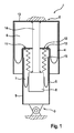
- the Fig. 1 shows pneumatic suspension and damping device 1 for vehicles, which is fixed to the body in the upper region 2 and fastened to a suspension in the lower region 3.
- the suspension and damping device has two filled with compressed gas air springs 4, 5, which form two variable in volume respectively working chambers 6, 7, which are arranged concentrically one above the other.
- the air springs each roll on a rolling contour, namely the lower air spring 5 on the rolling piston 8 and the upper air spring 4 on the outer surface of a provided for the lower air spring 5 outer and guide cylinder 9, i. a hollow cylinder, which then forms the rolling contour with its outer surface.
- the work spaces are connected by flow in two directions and possibly adjustable throttle bodies 10, 11 with each other.
- the upper cover 12 of the second air spring 5 is fixedly connected via the outer and guide cylinder 9 to the suspension.
- the upper lid 13 of the first air spring 4 is connected via a centrally and concentrically within the working chambers 6, 7 and guided by the cover 12 of the second air spring 5 guided rod 14 with the lower rolling piston 8 of the second air spring in combination.
- the second working space 7 is sealed with respect to the first working space 6 with a bellows 15 which surrounds the rod 14.
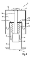
- Fig. 2 shows a schematic diagram of another embodiment of a pneumatic suspension and damping device according to the invention, which differs from the embodiment in Fig. 1 only differs in that the outer and guide cylinder 9 is formed directly on the suspension or is designed as part of the suspension.
Landscapes
- Engineering & Computer Science (AREA)
- Mechanical Engineering (AREA)
- General Engineering & Computer Science (AREA)
- Vehicle Body Suspensions (AREA)
- Fluid-Damping Devices (AREA)
Applications Claiming Priority (1)
| Application Number | Priority Date | Filing Date | Title |
|---|---|---|---|
| DE200910026347 DE102009026347A1 (de) | 2009-08-07 | 2009-08-07 | Pneumatische Federungs- und Dämpfungsvorrichtung |
Publications (2)
| Publication Number | Publication Date |
|---|---|
| EP2281702A2 true EP2281702A2 (fr) | 2011-02-09 |
| EP2281702A3 EP2281702A3 (fr) | 2012-08-15 |
Family
ID=43244907
Family Applications (1)
| Application Number | Title | Priority Date | Filing Date |
|---|---|---|---|
| EP10167111A Withdrawn EP2281702A3 (fr) | 2009-08-07 | 2010-06-24 | Dispositif de suspension et d'amortissement pneumatique |
Country Status (2)
| Country | Link |
|---|---|
| EP (1) | EP2281702A3 (fr) |
| DE (1) | DE102009026347A1 (fr) |
Cited By (5)
| Publication number | Priority date | Publication date | Assignee | Title |
|---|---|---|---|---|
| WO2013052930A3 (fr) * | 2011-10-05 | 2013-10-10 | Firestone Industrial Products Company, Llc | Ensemble ressort et amortisseur à gaz et procédé associé |
| RU2588554C2 (ru) * | 2011-10-05 | 2016-06-27 | ФАЙРСТОУН ИНДАСТРИАЛ ПРОДАКТС КОМПАНИ, ЭлЭлСи | Узел пневматической пружины и газонаполненного амортизатора и способ его сборки (варианты) |
| CN107420717A (zh) * | 2017-06-09 | 2017-12-01 | 浙江大学 | 一种气囊型低刚度悬吊装置 |
| CN113915275A (zh) * | 2021-10-29 | 2022-01-11 | 新一代汽车底盘系统(马鞍山)有限公司 | 一种空气弹簧及具有该空气弹簧的空气悬架 |
| CN116464737A (zh) * | 2023-06-05 | 2023-07-21 | 济南弋泽展特机械有限公司 | 一种空气弹簧减振器长度调节装置 |
Citations (2)
| Publication number | Priority date | Publication date | Assignee | Title |
|---|---|---|---|---|
| DE2406835A1 (de) | 1974-02-13 | 1975-08-14 | Gold Henning Dipl Ing | Federungs- und daempfungsvorrichtung, insbesondere fuer fahrzeuge |
| DE3436664A1 (de) | 1983-10-07 | 1985-05-02 | Bridgestone Corp., Tokio/Tokyo | Membran-luftfeder |
Family Cites Families (4)
| Publication number | Priority date | Publication date | Assignee | Title |
|---|---|---|---|---|
| DE102005018130A1 (de) * | 2005-04-20 | 2006-11-02 | Carl Freudenberg Kg | Luftfederdämpfer |
| DE102006007000A1 (de) * | 2006-01-20 | 2007-10-04 | Continental Aktiengesellschaft | Luftfeder- und Dämpfereinheit mit Zuganschlag |
| DE102007003063A1 (de) * | 2007-01-20 | 2008-07-31 | Carl Freudenberg Kg | Verstellbares Luftfeder-Dämpfer-Element |
| AU2009268503B2 (en) * | 2008-07-09 | 2014-05-08 | Firestone Industrial Products Company, Llc | Gas spring and gas damper assembly and method |
-
2009
- 2009-08-07 DE DE200910026347 patent/DE102009026347A1/de not_active Withdrawn
-
2010
- 2010-06-24 EP EP10167111A patent/EP2281702A3/fr not_active Withdrawn
Patent Citations (2)
| Publication number | Priority date | Publication date | Assignee | Title |
|---|---|---|---|---|
| DE2406835A1 (de) | 1974-02-13 | 1975-08-14 | Gold Henning Dipl Ing | Federungs- und daempfungsvorrichtung, insbesondere fuer fahrzeuge |
| DE3436664A1 (de) | 1983-10-07 | 1985-05-02 | Bridgestone Corp., Tokio/Tokyo | Membran-luftfeder |
Cited By (9)
| Publication number | Priority date | Publication date | Assignee | Title |
|---|---|---|---|---|
| WO2013052930A3 (fr) * | 2011-10-05 | 2013-10-10 | Firestone Industrial Products Company, Llc | Ensemble ressort et amortisseur à gaz et procédé associé |
| AU2012318388B2 (en) * | 2011-10-05 | 2016-01-07 | Firestone Industrial Products Company, Llc | Gas spring and gas damper assembly and method |
| US9290073B2 (en) | 2011-10-05 | 2016-03-22 | Firestone Industrial Products Company, Llc | Gas spring and gas damper assembly and method |
| RU2588554C2 (ru) * | 2011-10-05 | 2016-06-27 | ФАЙРСТОУН ИНДАСТРИАЛ ПРОДАКТС КОМПАНИ, ЭлЭлСи | Узел пневматической пружины и газонаполненного амортизатора и способ его сборки (варианты) |
| US9809075B2 (en) | 2011-10-05 | 2017-11-07 | Firestone Industrial Products Company, Llc | Gas spring and gas damper assembly and method |
| CN107420717A (zh) * | 2017-06-09 | 2017-12-01 | 浙江大学 | 一种气囊型低刚度悬吊装置 |
| CN113915275A (zh) * | 2021-10-29 | 2022-01-11 | 新一代汽车底盘系统(马鞍山)有限公司 | 一种空气弹簧及具有该空气弹簧的空气悬架 |
| CN113915275B (zh) * | 2021-10-29 | 2024-01-19 | 新一代汽车底盘系统(马鞍山)有限公司 | 一种空气弹簧及具有该空气弹簧的空气悬架 |
| CN116464737A (zh) * | 2023-06-05 | 2023-07-21 | 济南弋泽展特机械有限公司 | 一种空气弹簧减振器长度调节装置 |
Also Published As
| Publication number | Publication date |
|---|---|
| EP2281702A3 (fr) | 2012-08-15 |
| DE102009026347A1 (de) | 2011-04-14 |
Similar Documents
| Publication | Publication Date | Title |
|---|---|---|
| EP0033839B1 (fr) | Unité télescopique hydropneumatique auto-pompante de suspension et amortissement comportant un contrôle d'assiette intérieur | |
| EP1344957B1 (fr) | Dispositif de suspension et d'amortissement pneumatique | |
| EP1429045B1 (fr) | Arrangement de ressort pneumatique | |
| DE3135043A1 (de) | "stuetzlager zum einbau zwischen ein daempfer- oder federbein und einer gegenueber den achsen abgefederten karosserie eines fahrzeuges, insbesondere eines kraftfahrzeuges" | |
| DE3536867C2 (de) | Federbein für eine Fahrzeugradaufhängung | |
| EP1831582B1 (fr) | Unite d'amortissement a ressort pneumatique | |
| EP1366309A1 (fr) | Ensemble amortisseur a ressort a pression de gaz | |
| EP1831581B1 (fr) | Unite ressort et amortisseur pneumatique de guidage de roue | |
| DE102014101090B4 (de) | Stromabnehmer-Feder-Dämpfer-Baueinheit | |
| EP2281702A2 (fr) | Dispositif de suspension et d'amortissement pneumatique | |
| EP1261813B1 (fr) | Amortisseur pneumatique comportant un carter en deux parties | |
| EP3158217B1 (fr) | Palier hydraulique et véhicule à moteur équipé d'un tel palier hydraulique | |
| EP1837548A1 (fr) | Unité d'amortissement et de ressort à air dotée d'un pli roulé détendu | |
| EP1681182B1 (fr) | Support de ressort | |
| EP3221613B1 (fr) | Palier hydraulique et véhicule à moteur équipé d'un tel palier hydraulique | |
| EP1947360A1 (fr) | Elément d'amortisseur à ressort réglable | |
| DE3445984A1 (de) | Luftfeder-radaufhaengung | |
| WO2016078807A1 (fr) | Palier hydraulique et véhicule à moteur équipé d'un tel palier hydraulique | |
| DE19617840C2 (de) | Zweikammer-Motorlager mit Entkopplungseinrichtung | |
| EP1724491B1 (fr) | Amortisseur hydraulique | |
| DE102018106717A1 (de) | Luftfeder | |
| EP1688639A1 (fr) | Support hydraulique | |
| EP1785291B1 (fr) | Jambe de suspension pour amortisseur d'un véhicule | |
| EP3800369A1 (fr) | Palier hydraulique | |
| DE102004028661A1 (de) | Motorlager mit hydraulischem Dämpfer |
Legal Events
| Date | Code | Title | Description |
|---|---|---|---|
| PUAI | Public reference made under article 153(3) epc to a published international application that has entered the european phase |
Free format text: ORIGINAL CODE: 0009012 |
|
| AK | Designated contracting states |
Kind code of ref document: A2 Designated state(s): AL AT BE BG CH CY CZ DE DK EE ES FI FR GB GR HR HU IE IS IT LI LT LU LV MC MK MT NL NO PL PT RO SE SI SK SM TR |
|
| AX | Request for extension of the european patent |
Extension state: BA ME RS |
|
| PUAL | Search report despatched |
Free format text: ORIGINAL CODE: 0009013 |
|
| AK | Designated contracting states |
Kind code of ref document: A3 Designated state(s): AL AT BE BG CH CY CZ DE DK EE ES FI FR GB GR HR HU IE IS IT LI LT LU LV MC MK MT NL NO PL PT RO SE SI SK SM TR |
|
| AX | Request for extension of the european patent |
Extension state: BA ME RS |
|
| RIC1 | Information provided on ipc code assigned before grant |
Ipc: F16F 9/04 20060101ALI20120706BHEP Ipc: B60G 15/12 20060101ALI20120706BHEP Ipc: B60G 11/27 20060101AFI20120706BHEP |
|
| 17P | Request for examination filed |
Effective date: 20130215 |
|
| GRAP | Despatch of communication of intention to grant a patent |
Free format text: ORIGINAL CODE: EPIDOSNIGR1 |
|
| INTG | Intention to grant announced |
Effective date: 20130416 |
|
| STAA | Information on the status of an ep patent application or granted ep patent |
Free format text: STATUS: THE APPLICATION HAS BEEN WITHDRAWN |
|
| 18W | Application withdrawn |
Effective date: 20130604 |