EP2281702A2 - Pneumatic suspension and dampening device - Google Patents
Pneumatic suspension and dampening device Download PDFInfo
- Publication number
- EP2281702A2 EP2281702A2 EP10167111A EP10167111A EP2281702A2 EP 2281702 A2 EP2281702 A2 EP 2281702A2 EP 10167111 A EP10167111 A EP 10167111A EP 10167111 A EP10167111 A EP 10167111A EP 2281702 A2 EP2281702 A2 EP 2281702A2
- Authority
- EP
- European Patent Office
- Prior art keywords
- air spring
- suspension
- damping device
- air
- rod
- Prior art date
- Legal status (The legal status is an assumption and is not a legal conclusion. Google has not performed a legal analysis and makes no representation as to the accuracy of the status listed.)
- Withdrawn
Links
Images
Classifications
-
- B—PERFORMING OPERATIONS; TRANSPORTING
- B60—VEHICLES IN GENERAL
- B60G—VEHICLE SUSPENSION ARRANGEMENTS
- B60G11/00—Resilient suspensions characterised by arrangement, location or kind of springs
- B60G11/26—Resilient suspensions characterised by arrangement, location or kind of springs having fluid springs only, e.g. hydropneumatic springs
- B60G11/27—Resilient suspensions characterised by arrangement, location or kind of springs having fluid springs only, e.g. hydropneumatic springs wherein the fluid is a gas
-
- B—PERFORMING OPERATIONS; TRANSPORTING
- B60—VEHICLES IN GENERAL
- B60G—VEHICLE SUSPENSION ARRANGEMENTS
- B60G15/00—Resilient suspensions characterised by arrangement, location or type of combined spring and vibration damper, e.g. telescopic type
- B60G15/08—Resilient suspensions characterised by arrangement, location or type of combined spring and vibration damper, e.g. telescopic type having fluid spring
- B60G15/12—Resilient suspensions characterised by arrangement, location or type of combined spring and vibration damper, e.g. telescopic type having fluid spring and fluid damper
-
- F—MECHANICAL ENGINEERING; LIGHTING; HEATING; WEAPONS; BLASTING
- F16—ENGINEERING ELEMENTS AND UNITS; GENERAL MEASURES FOR PRODUCING AND MAINTAINING EFFECTIVE FUNCTIONING OF MACHINES OR INSTALLATIONS; THERMAL INSULATION IN GENERAL
- F16F—SPRINGS; SHOCK-ABSORBERS; MEANS FOR DAMPING VIBRATION
- F16F9/00—Springs, vibration-dampers, shock-absorbers, or similarly-constructed movement-dampers using a fluid or the equivalent as damping medium
- F16F9/02—Springs, vibration-dampers, shock-absorbers, or similarly-constructed movement-dampers using a fluid or the equivalent as damping medium using gas only or vacuum
- F16F9/04—Springs, vibration-dampers, shock-absorbers, or similarly-constructed movement-dampers using a fluid or the equivalent as damping medium using gas only or vacuum in a chamber with a flexible wall
- F16F9/0472—Springs, vibration-dampers, shock-absorbers, or similarly-constructed movement-dampers using a fluid or the equivalent as damping medium using gas only or vacuum in a chamber with a flexible wall characterised by comprising a damping device
-
- F—MECHANICAL ENGINEERING; LIGHTING; HEATING; WEAPONS; BLASTING
- F16—ENGINEERING ELEMENTS AND UNITS; GENERAL MEASURES FOR PRODUCING AND MAINTAINING EFFECTIVE FUNCTIONING OF MACHINES OR INSTALLATIONS; THERMAL INSULATION IN GENERAL
- F16F—SPRINGS; SHOCK-ABSORBERS; MEANS FOR DAMPING VIBRATION
- F16F9/00—Springs, vibration-dampers, shock-absorbers, or similarly-constructed movement-dampers using a fluid or the equivalent as damping medium
- F16F9/02—Springs, vibration-dampers, shock-absorbers, or similarly-constructed movement-dampers using a fluid or the equivalent as damping medium using gas only or vacuum
- F16F9/04—Springs, vibration-dampers, shock-absorbers, or similarly-constructed movement-dampers using a fluid or the equivalent as damping medium using gas only or vacuum in a chamber with a flexible wall
- F16F9/049—Springs, vibration-dampers, shock-absorbers, or similarly-constructed movement-dampers using a fluid or the equivalent as damping medium using gas only or vacuum in a chamber with a flexible wall multi-chamber units
-
- B—PERFORMING OPERATIONS; TRANSPORTING
- B60—VEHICLES IN GENERAL
- B60G—VEHICLE SUSPENSION ARRANGEMENTS
- B60G2202/00—Indexing codes relating to the type of spring, damper or actuator
- B60G2202/20—Type of damper
- B60G2202/24—Fluid damper
- B60G2202/242—Pneumatic damper
-
- B—PERFORMING OPERATIONS; TRANSPORTING
- B60—VEHICLES IN GENERAL
- B60G—VEHICLE SUSPENSION ARRANGEMENTS
- B60G2206/00—Indexing codes related to the manufacturing of suspensions: constructional features, the materials used, procedures or tools
- B60G2206/01—Constructional features of suspension elements, e.g. arms, dampers, springs
- B60G2206/40—Constructional features of dampers and/or springs
- B60G2206/41—Dampers
-
- B—PERFORMING OPERATIONS; TRANSPORTING
- B60—VEHICLES IN GENERAL
- B60G—VEHICLE SUSPENSION ARRANGEMENTS
- B60G2206/00—Indexing codes related to the manufacturing of suspensions: constructional features, the materials used, procedures or tools
- B60G2206/01—Constructional features of suspension elements, e.g. arms, dampers, springs
- B60G2206/40—Constructional features of dampers and/or springs
- B60G2206/42—Springs
- B60G2206/424—Plunger or top retainer construction for bellows or rolling lobe type air springs
Definitions
- the invention relates to a pneumatic suspension and damping device, in particular for vehicles, which is fastened preferably in the upper region of the body and in the lower region to a suspension comprising at least two filled with compressed gas, connectable via an air connection to a compressed gas source, hermetically sealed air springs , Each air spring forms a variable in its volume work space, ie at least partially encloses the working space.
- the air springs roll on a rolling contour and are connected via a flow in two directions throttle body in connection.
- the air springs are arranged one above the other and the rolling contour of the first air spring by the second air spring predetermined such that the first air spring rolls over the second air spring.
- An upper cover of the first air spring is connected via a connecting element with a rolling piston of the second air spring in conjunction and a cover of the second air spring with the suspension in conjunction
- the DE-OS 24 06 835 A1 discloses a suspension and damping device with air damping.
- suspension and damping device are a suspension space, which is reduced by means of a rolling bellows during compression and increased rebound, and a damper chamber, which is variable by means of a rolling bellows in its volume, via a flow-through in both directions throttle body in connection ,
- the in its cross-section H-shaped housing of the suspension and damping device is firmly connected to the vehicle frame.
- the respective rolling piston of the suspension and Damping rooms are supported against the respective upper and / or lower wishbones of the suspension.
- This embodiment of a suspension and damping device with the cross-sectionally H-shaped housing leads to a complex construction of the suspension, in particular the vehicle-mounted connection, and to an increased space requirement.
- the DE 3436664 A1 discloses a membrane air spring, which also provides suspension and damping and has two different sized working chambers, which are each bounded in part by rolling bellows to the outside.
- the rolling bellows are supported and roll on outer cylindrical surfaces axially movable and designed as a hollow piston housing parts.
- the different sized working chambers are separated by a wall provided with throttle openings. Through the throttle openings, air can flow from one working chamber to the other, the resulting dissipation generating the damping work.
- the diaphragm air spring is in its basic construction, in which the housing parts designed as a hollow piston are connected to a guided in the partition central rod, associated with considerable friction losses in this guide and also has a considerable size.
- the object of the invention is to provide a suitable for a vehicle pneumatic suspension and damping device, the space is small and can be installed without additional design effort in the space of conventional suspension and damping devices and no - especially dry - friction has can lead to acoustic problems.
- the space is particularly low in this embodiment and particularly conducive to a compact design of the entire shock absorber.
- the second air spring is guided in a subsequent to its upper lid hollow cylinder and firmly connected by the latter to the suspension. This achieves a rigid and predetermined rolling contour for the first air spring and a simultaneous support of the second air spring, so that the latter can be made relatively thin.
- the second air spring forms a working space which is sealed with respect to the concentrically arranged rod with a bellows.
- the bellows then forms a particularly flexible seal between the two working spaces, in particular when the bellows is designed as an air supply channel for arranged in the lower rolling piston throttles.
- Such a formation of a dual function is also favorable for the further minimization of the installation space.
- throttle bodies are arranged in the upper lid of the second air spring. This also serves to integrate components and thus a particularly compact design of the pneumatic suspension and damping device.
- the rod is designed for receiving electrical cables and / or medium or power lines.
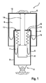
- the Fig. 1 shows pneumatic suspension and damping device 1 for vehicles, which is fixed to the body in the upper region 2 and fastened to a suspension in the lower region 3.
- the suspension and damping device has two filled with compressed gas air springs 4, 5, which form two variable in volume respectively working chambers 6, 7, which are arranged concentrically one above the other.
- the air springs each roll on a rolling contour, namely the lower air spring 5 on the rolling piston 8 and the upper air spring 4 on the outer surface of a provided for the lower air spring 5 outer and guide cylinder 9, i. a hollow cylinder, which then forms the rolling contour with its outer surface.
- the work spaces are connected by flow in two directions and possibly adjustable throttle bodies 10, 11 with each other.
- the upper cover 12 of the second air spring 5 is fixedly connected via the outer and guide cylinder 9 to the suspension.
- the upper lid 13 of the first air spring 4 is connected via a centrally and concentrically within the working chambers 6, 7 and guided by the cover 12 of the second air spring 5 guided rod 14 with the lower rolling piston 8 of the second air spring in combination.
- the second working space 7 is sealed with respect to the first working space 6 with a bellows 15 which surrounds the rod 14.
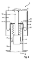
- Fig. 2 shows a schematic diagram of another embodiment of a pneumatic suspension and damping device according to the invention, which differs from the embodiment in Fig. 1 only differs in that the outer and guide cylinder 9 is formed directly on the suspension or is designed as part of the suspension.
Landscapes
- Engineering & Computer Science (AREA)
- Mechanical Engineering (AREA)
- General Engineering & Computer Science (AREA)
- Vehicle Body Suspensions (AREA)
- Fluid-Damping Devices (AREA)
Abstract
Description
Die Erfindung betrifft ein eine pneumatische Federungs- und Dämpfungsvorrichtung, insbesondere für Fahrzeuge, welche vorzugsweise im oberen Bereich karosseriefest und im unteren Bereich an einer Radaufhängung befestigbar ist, enthaltend mindestens zwei mit Druckgas gefüllte, über einen Luftanschluss an eine Druckgasquelle anschließbare, hermetisch abgeschlossene Luftfedern aufweist, wobei jede Luftfeder einen jeweils in seinem Volumen veränderbaren Arbeitsraum bildet, d.h. den Arbeitsraum mindestens teilweise umschließt. Die Luftfedern rollen auf einer Abrollkontur ab und stehen über ein in zwei Richtungen durchströmbares Drosselorgan in Verbindung. Dabei sind die Luftfedern übereinander angeordnet sind und die Abrollkontur der ersten Luftfeder durch die zweite Luftfeder derart vorgegeben, dass die erste Luftfeder über der zweiten Luftfeder abrollt. Ein oberer Deckel der ersten Luftfeder steht über ein Verbindungselement mit einem Abrollkolben der zweiten Luftfeder in Verbindung und ein Deckel der zweiten Luftfeder mit der Radaufhängung in VerbindungThe invention relates to a pneumatic suspension and damping device, in particular for vehicles, which is fastened preferably in the upper region of the body and in the lower region to a suspension comprising at least two filled with compressed gas, connectable via an air connection to a compressed gas source, hermetically sealed air springs , Each air spring forms a variable in its volume work space, ie at least partially encloses the working space. The air springs roll on a rolling contour and are connected via a flow in two directions throttle body in connection. The air springs are arranged one above the other and the rolling contour of the first air spring by the second air spring predetermined such that the first air spring rolls over the second air spring. An upper cover of the first air spring is connected via a connecting element with a rolling piston of the second air spring in conjunction and a cover of the second air spring with the suspension in conjunction
Die
Die
Aufgabe der Erfindung ist es, eine für ein Fahrzeug geeignete pneumatische Federungs- und Dämpfungsvorrichtung zu schaffen, deren Bauraum gering ist und die ohne konstruktiven Mehraufwand in den Bauraum von herkömmlichen Federungs- und Dämpfungsvorrichtungen eingebaut werden kann und keine - insbesondere trockene - Reibung aufweist, welche zu akustischen Problemen führen kann.The object of the invention is to provide a suitable for a vehicle pneumatic suspension and damping device, the space is small and can be installed without additional design effort in the space of conventional suspension and damping devices and no - especially dry - friction has can lead to acoustic problems.
Gelöst wird diese Aufgabe durch die Merkmale des Hauptanspruchs. Weitere vorteilhafte Ausbildungen sind in den Unteransprüchen offenbart.This object is achieved by the features of the main claim. Further advantageous embodiments are disclosed in the subclaims.
Dabei steht ein oberer Deckel der ersten Luftfeder über eine mittig und konzentrisch innerhalb der Arbeitsräume abgeordnete und durch den Deckel er zweiten Luftfeder geführten Stange mit einem unteren Abrollkolben der zweiten Luftfeder in Verbindung. Der Bauraum ist bei dieser Ausführung besonders gering und für eine kompakte Ausbildung des gesamten Federbeines besonders förderlich.In this case, an upper cover of the first air spring via a centrally and concentrically within the working chambers and seconded by the lid he second air spring guided rod with a lower rolling piston of the second air spring in conjunction. The space is particularly low in this embodiment and particularly conducive to a compact design of the entire shock absorber.
Eine vorteilhafte Weiterbildung besteht darin, dass die zweite Luftfeder in einem an ihren oberen Deckel anschließenden Hohlzylinder geführt und durch letzteren an der Radaufhängung fest angeschlossen ist. Dadurch erreicht man eine starre und vorgegebene Abrollkontur für die erste Luftfeder und eine gleichzeitige Stützung der zweiten Luftfeder, sodass letztere relativ dünn ausgeführt werden kann.An advantageous development is that the second air spring is guided in a subsequent to its upper lid hollow cylinder and firmly connected by the latter to the suspension. This achieves a rigid and predetermined rolling contour for the first air spring and a simultaneous support of the second air spring, so that the latter can be made relatively thin.
Eine weitere vorteilhafte Weiterbildung besteht darin, dass die zweite Luftfeder einen Arbeitsraum bildet, der gegenüber der konzentrisch angeordneten Stange mit einem Faltenbalg abgedichtet ist. Der Faltenbalg bildet dann eine besonders flexible Abdichtung zwischen den beiden Arbeitsräumen, insbesondere dann, wenn der Faltenbalg als Luftzufuhrkanal für im unteren Abrollkolben angeordnete Drosseln ausgebildet ist. Eine solche Ausbildung einer Doppelfunktion ist ebenfalls günstig für die weitere Minimierung des Bauraumes.A further advantageous development is that the second air spring forms a working space which is sealed with respect to the concentrically arranged rod with a bellows. The bellows then forms a particularly flexible seal between the two working spaces, in particular when the bellows is designed as an air supply channel for arranged in the lower rolling piston throttles. Such a formation of a dual function is also favorable for the further minimization of the installation space.
Eine weitere vorteilhafte Weiterbildung besteht darin, dass die Drosselorgane im oberen Deckel der zweiten Luftfeder angeordnet sind. Auch dies dient einer integration von Bauteilen und damit einer besonders kompakten Ausbildung der pneumatische Federungs- und Dämpfungsvorrichtung.A further advantageous development is that the throttle bodies are arranged in the upper lid of the second air spring. This also serves to integrate components and thus a particularly compact design of the pneumatic suspension and damping device.
Eine weitere vorteilhafte Weiterbildung in diesem Sinne besteht darin, dass die Stange für Aufnahme von elektrischen Kabeln und/oder von Mediums- oder Energieleitungen ausgebildet ist.A further advantageous development in this sense is that the rod is designed for receiving electrical cables and / or medium or power lines.
Anhand eines Ausführungsbeispiels soll die Erfindung näher erläutert werden. Es zeigen
- Fig. 1
- eine Prinzipskizze einer erfindungsgemäßen pneumatischen Federungs- und Dämpfungsvorrichtung
- Fig. 2
- eine Prinzipskizze einer weiteren Ausführung einer erfindungsgemäßen pneumatischen Federungs- und Dämpfungsvorrichtung
- Fig. 1
- a schematic diagram of a pneumatic suspension and damping device according to the invention
- Fig. 2
- a schematic diagram of another embodiment of a pneumatic suspension and damping device according to the invention
Die
Die Luftfedern rollen jeweils auf einer Abrollkontur ab, nämlich die untere Luftfeder 5 auf dem Abrollkolben 8 und die obere Luftfeder 4 auf der Außenfläche eines für die untere Luftfeder 5 vorgesehenen Außen- und Führungszylinders 9, d.h. eine Hohlzylinders, welcher dann die mit seiner Außenfläche die Abrollkontur bildet. Die Arbeitsräume stehen über in zwei Richtungen durchströmbare und ggf. verstellbare Drosselorgane 10, 11 miteinander in Verbindung.The air springs each roll on a rolling contour, namely the
Der oberer Deckel 12 der zweiten Luftfeder 5 ist über den Außen- und Führungszylinders 9 an der Radaufhängung fest angeschlossen.The
Der oberer Deckel 13 der ersten Luftfeder 4 steht über eine mittig und konzentrisch innerhalb der Arbeitsräume 6, 7 angeordnete und durch den Deckel 12 der zweiten Luftfeder 5 geführten Stange 14 mit dem unteren Abrollkolben 8 der zweiten Luftfeder in Verbindung.The
Der zweite Arbeitsraum 7 ist gegenüber dem ersten Arbeitsraum 6 mit einem Faltenbalg 15 abgedichtet, der die Stange 14 umgibt.The second working
- 11
- Pneumatische Federungs- und DämpfungsvorrichtungPneumatic suspension and damping device
- 22
- Oberer Bereichupper area
- 33
- Unterer BereichLower area
- 44
- Luftfederair spring
- 55
- Luftfederair spring
- 66
- Arbeitsraumworking space
- 77
- Arbeitsraumworking space
- 88th
- Abrollkolbenroll-off
- 99
- Außen- und FührungszylinderOuter and guide cylinder
- 1010
- Drosselorganthrottle member
- 1111
- Drosselorganthrottle member
- 1212
- Deckel der zweiten LuftfederCover of the second air spring
- 1313
- Deckel der ersten LuftfederCover of the first air spring
- 1414
- Stangepole
- 1515
- Faltenbalgbellow
Claims (6)
Applications Claiming Priority (1)
| Application Number | Priority Date | Filing Date | Title |
|---|---|---|---|
| DE200910026347 DE102009026347A1 (en) | 2009-08-07 | 2009-08-07 | Pneumatic suspension and damping device |
Publications (2)
| Publication Number | Publication Date |
|---|---|
| EP2281702A2 true EP2281702A2 (en) | 2011-02-09 |
| EP2281702A3 EP2281702A3 (en) | 2012-08-15 |
Family
ID=43244907
Family Applications (1)
| Application Number | Title | Priority Date | Filing Date |
|---|---|---|---|
| EP10167111A Withdrawn EP2281702A3 (en) | 2009-08-07 | 2010-06-24 | Pneumatic suspension and dampening device |
Country Status (2)
| Country | Link |
|---|---|
| EP (1) | EP2281702A3 (en) |
| DE (1) | DE102009026347A1 (en) |
Cited By (5)
| Publication number | Priority date | Publication date | Assignee | Title |
|---|---|---|---|---|
| WO2013052930A3 (en) * | 2011-10-05 | 2013-10-10 | Firestone Industrial Products Company, Llc | Gas spring and gas damper assembly and method |
| RU2588554C2 (en) * | 2011-10-05 | 2016-06-27 | ФАЙРСТОУН ИНДАСТРИАЛ ПРОДАКТС КОМПАНИ, ЭлЭлСи | Unit of pneumatic spring and gas-filled shock absorber and method for assembly thereof (versions) |
| CN107420717A (en) * | 2017-06-09 | 2017-12-01 | 浙江大学 | A kind of bladder-type Low rigidity suspension apparatus |
| CN113915275A (en) * | 2021-10-29 | 2022-01-11 | 新一代汽车底盘系统(马鞍山)有限公司 | An air spring and an air suspension having the same |
| CN116464737A (en) * | 2023-06-05 | 2023-07-21 | 济南弋泽展特机械有限公司 | Length adjusting device of air spring shock absorber |
Citations (2)
| Publication number | Priority date | Publication date | Assignee | Title |
|---|---|---|---|---|
| DE2406835A1 (en) | 1974-02-13 | 1975-08-14 | Gold Henning Dipl Ing | Vehicle pneumatic suspension element - with opposingly operating elastic elements linked by throttle valves for damping action |
| DE3436664A1 (en) | 1983-10-07 | 1985-05-02 | Bridgestone Corp., Tokio/Tokyo | DIAPHRAGM AIR SPRING |
Family Cites Families (4)
| Publication number | Priority date | Publication date | Assignee | Title |
|---|---|---|---|---|
| DE102005018130A1 (en) * | 2005-04-20 | 2006-11-02 | Carl Freudenberg Kg | Air spring damper |
| DE102006007000A1 (en) * | 2006-01-20 | 2007-10-04 | Continental Aktiengesellschaft | Air spring and damper unit with cable stop |
| DE102007003063A1 (en) * | 2007-01-20 | 2008-07-31 | Carl Freudenberg Kg | Adjustable air spring damper element |
| AU2009268503B2 (en) * | 2008-07-09 | 2014-05-08 | Firestone Industrial Products Company, Llc | Gas spring and gas damper assembly and method |
-
2009
- 2009-08-07 DE DE200910026347 patent/DE102009026347A1/en not_active Withdrawn
-
2010
- 2010-06-24 EP EP10167111A patent/EP2281702A3/en not_active Withdrawn
Patent Citations (2)
| Publication number | Priority date | Publication date | Assignee | Title |
|---|---|---|---|---|
| DE2406835A1 (en) | 1974-02-13 | 1975-08-14 | Gold Henning Dipl Ing | Vehicle pneumatic suspension element - with opposingly operating elastic elements linked by throttle valves for damping action |
| DE3436664A1 (en) | 1983-10-07 | 1985-05-02 | Bridgestone Corp., Tokio/Tokyo | DIAPHRAGM AIR SPRING |
Cited By (9)
| Publication number | Priority date | Publication date | Assignee | Title |
|---|---|---|---|---|
| WO2013052930A3 (en) * | 2011-10-05 | 2013-10-10 | Firestone Industrial Products Company, Llc | Gas spring and gas damper assembly and method |
| AU2012318388B2 (en) * | 2011-10-05 | 2016-01-07 | Firestone Industrial Products Company, Llc | Gas spring and gas damper assembly and method |
| US9290073B2 (en) | 2011-10-05 | 2016-03-22 | Firestone Industrial Products Company, Llc | Gas spring and gas damper assembly and method |
| RU2588554C2 (en) * | 2011-10-05 | 2016-06-27 | ФАЙРСТОУН ИНДАСТРИАЛ ПРОДАКТС КОМПАНИ, ЭлЭлСи | Unit of pneumatic spring and gas-filled shock absorber and method for assembly thereof (versions) |
| US9809075B2 (en) | 2011-10-05 | 2017-11-07 | Firestone Industrial Products Company, Llc | Gas spring and gas damper assembly and method |
| CN107420717A (en) * | 2017-06-09 | 2017-12-01 | 浙江大学 | A kind of bladder-type Low rigidity suspension apparatus |
| CN113915275A (en) * | 2021-10-29 | 2022-01-11 | 新一代汽车底盘系统(马鞍山)有限公司 | An air spring and an air suspension having the same |
| CN113915275B (en) * | 2021-10-29 | 2024-01-19 | 新一代汽车底盘系统(马鞍山)有限公司 | Air spring and air suspension with same |
| CN116464737A (en) * | 2023-06-05 | 2023-07-21 | 济南弋泽展特机械有限公司 | Length adjusting device of air spring shock absorber |
Also Published As
| Publication number | Publication date |
|---|---|
| EP2281702A3 (en) | 2012-08-15 |
| DE102009026347A1 (en) | 2011-04-14 |
Similar Documents
| Publication | Publication Date | Title |
|---|---|---|
| EP0033839B1 (en) | Self-pumping hydropneumatic telescopic spring damping unit with interior level control | |
| EP1344957B1 (en) | Pneumatic suspension and damping device | |
| EP1429045B1 (en) | Air spring arrangement | |
| DE3135043A1 (en) | "SUPPORT BEARING FOR INSTALLATION BETWEEN A SHOCK ABSORBER OR SHOCK ABSORBER AND A BODY OF A VEHICLE CUSHIONED ABOVE THE AXLES, IN PARTICULAR A MOTOR VEHICLE" | |
| DE3536867C2 (en) | Suspension strut for a vehicle wheel suspension | |
| EP1831582B1 (en) | Pneumatic spring shock absorber unit | |
| EP1366309A1 (en) | Gas spring damper unit | |
| EP1831581B1 (en) | Wheel-guiding pneumatic spring and damper unit | |
| DE102014101090B4 (en) | Pantograph-spring-damper assembly | |
| EP2281702A2 (en) | Pneumatic suspension and dampening device | |
| EP1261813B1 (en) | Air spring with two part housing | |
| EP3158217B1 (en) | Hydraulic mount and motor vehicle having such a hydraulic mount | |
| EP1837548A1 (en) | Pneumatic spring and damping unit with decompression bellows | |
| EP1681182B1 (en) | Spring support | |
| EP3221613B1 (en) | Hydraulic mount and motor vehicle comprising a hydraulic mount of this type | |
| EP1947360A1 (en) | Adjustable pneumatic spring damper element | |
| DE3445984A1 (en) | Air-spring wheel suspension | |
| WO2016078807A1 (en) | Hydraulic mount and motor vehicle comprising a hydraulic mount of this type | |
| DE19617840C2 (en) | Two-chamber engine mount with decoupling device | |
| EP1724491B1 (en) | Hydraulic shock absorber | |
| DE102018106717A1 (en) | air spring | |
| EP1688639A1 (en) | Hydraulic support | |
| EP1785291B1 (en) | Shock absorber suspension strut for a vehicle | |
| EP3800369A1 (en) | Hydraulic bearing | |
| DE102004028661A1 (en) | Engine mounting with hydraulic damper has working chamber bounded by volumetrically stiff rolling bellows between separating plate and a roll-off piston |
Legal Events
| Date | Code | Title | Description |
|---|---|---|---|
| PUAI | Public reference made under article 153(3) epc to a published international application that has entered the european phase |
Free format text: ORIGINAL CODE: 0009012 |
|
| AK | Designated contracting states |
Kind code of ref document: A2 Designated state(s): AL AT BE BG CH CY CZ DE DK EE ES FI FR GB GR HR HU IE IS IT LI LT LU LV MC MK MT NL NO PL PT RO SE SI SK SM TR |
|
| AX | Request for extension of the european patent |
Extension state: BA ME RS |
|
| PUAL | Search report despatched |
Free format text: ORIGINAL CODE: 0009013 |
|
| AK | Designated contracting states |
Kind code of ref document: A3 Designated state(s): AL AT BE BG CH CY CZ DE DK EE ES FI FR GB GR HR HU IE IS IT LI LT LU LV MC MK MT NL NO PL PT RO SE SI SK SM TR |
|
| AX | Request for extension of the european patent |
Extension state: BA ME RS |
|
| RIC1 | Information provided on ipc code assigned before grant |
Ipc: F16F 9/04 20060101ALI20120706BHEP Ipc: B60G 15/12 20060101ALI20120706BHEP Ipc: B60G 11/27 20060101AFI20120706BHEP |
|
| 17P | Request for examination filed |
Effective date: 20130215 |
|
| GRAP | Despatch of communication of intention to grant a patent |
Free format text: ORIGINAL CODE: EPIDOSNIGR1 |
|
| INTG | Intention to grant announced |
Effective date: 20130416 |
|
| STAA | Information on the status of an ep patent application or granted ep patent |
Free format text: STATUS: THE APPLICATION HAS BEEN WITHDRAWN |
|
| 18W | Application withdrawn |
Effective date: 20130604 |