EP2280795B1 - Rotary-driven tool for cutting machining with a cutting body - Google Patents
Rotary-driven tool for cutting machining with a cutting body Download PDFInfo
- Publication number
- EP2280795B1 EP2280795B1 EP09734628.2A EP09734628A EP2280795B1 EP 2280795 B1 EP2280795 B1 EP 2280795B1 EP 09734628 A EP09734628 A EP 09734628A EP 2280795 B1 EP2280795 B1 EP 2280795B1
- Authority
- EP
- European Patent Office
- Prior art keywords
- dovetail
- cutting
- holder
- recess
- cutting head
- Prior art date
- Legal status (The legal status is an assumption and is not a legal conclusion. Google has not performed a legal analysis and makes no representation as to the accuracy of the status listed.)
- Active
Links
- 238000005520 cutting process Methods 0.000 title claims description 121
- 238000003754 machining Methods 0.000 title claims description 5
- 238000005553 drilling Methods 0.000 claims description 16
- 238000001816 cooling Methods 0.000 claims description 9
- 238000003780 insertion Methods 0.000 claims description 8
- 230000037431 insertion Effects 0.000 claims description 8
- 238000007373 indentation Methods 0.000 claims 2
- 239000002826 coolant Substances 0.000 description 11
- 229910000831 Steel Inorganic materials 0.000 description 2
- 238000004519 manufacturing process Methods 0.000 description 2
- 239000000463 material Substances 0.000 description 2
- 239000007787 solid Substances 0.000 description 2
- 239000010959 steel Substances 0.000 description 2
- 229910001315 Tool steel Inorganic materials 0.000 description 1
- 239000000919 ceramic Substances 0.000 description 1
- 230000001419 dependent effect Effects 0.000 description 1
- 238000011161 development Methods 0.000 description 1
- 230000018109 developmental process Effects 0.000 description 1
- 230000000694 effects Effects 0.000 description 1
- 230000003993 interaction Effects 0.000 description 1
- 238000005555 metalworking Methods 0.000 description 1
- 238000005457 optimization Methods 0.000 description 1
- 230000000284 resting effect Effects 0.000 description 1
Images


Classifications
-
- B—PERFORMING OPERATIONS; TRANSPORTING
- B23—MACHINE TOOLS; METAL-WORKING NOT OTHERWISE PROVIDED FOR
- B23B—TURNING; BORING
- B23B51/00—Tools for drilling machines
- B23B51/02—Twist drills
-
- B—PERFORMING OPERATIONS; TRANSPORTING
- B23—MACHINE TOOLS; METAL-WORKING NOT OTHERWISE PROVIDED FOR
- B23B—TURNING; BORING
- B23B51/00—Tools for drilling machines
- B23B51/06—Drills with lubricating or cooling equipment
-
- B—PERFORMING OPERATIONS; TRANSPORTING
- B23—MACHINE TOOLS; METAL-WORKING NOT OTHERWISE PROVIDED FOR
- B23B—TURNING; BORING
- B23B2251/00—Details of tools for drilling machines
- B23B2251/02—Connections between shanks and removable cutting heads
-
- Y—GENERAL TAGGING OF NEW TECHNOLOGICAL DEVELOPMENTS; GENERAL TAGGING OF CROSS-SECTIONAL TECHNOLOGIES SPANNING OVER SEVERAL SECTIONS OF THE IPC; TECHNICAL SUBJECTS COVERED BY FORMER USPC CROSS-REFERENCE ART COLLECTIONS [XRACs] AND DIGESTS
- Y10—TECHNICAL SUBJECTS COVERED BY FORMER USPC
- Y10S—TECHNICAL SUBJECTS COVERED BY FORMER USPC CROSS-REFERENCE ART COLLECTIONS [XRACs] AND DIGESTS
- Y10S408/00—Cutting by use of rotating axially moving tool
- Y10S408/713—Tool having detachable cutting edge
-
- Y—GENERAL TAGGING OF NEW TECHNOLOGICAL DEVELOPMENTS; GENERAL TAGGING OF CROSS-SECTIONAL TECHNOLOGIES SPANNING OVER SEVERAL SECTIONS OF THE IPC; TECHNICAL SUBJECTS COVERED BY FORMER USPC CROSS-REFERENCE ART COLLECTIONS [XRACs] AND DIGESTS
- Y10—TECHNICAL SUBJECTS COVERED BY FORMER USPC
- Y10T—TECHNICAL SUBJECTS COVERED BY FORMER US CLASSIFICATION
- Y10T408/00—Cutting by use of rotating axially moving tool
- Y10T408/44—Cutting by use of rotating axially moving tool with means to apply transient, fluent medium to work or product
- Y10T408/45—Cutting by use of rotating axially moving tool with means to apply transient, fluent medium to work or product including Tool with duct
-
- Y—GENERAL TAGGING OF NEW TECHNOLOGICAL DEVELOPMENTS; GENERAL TAGGING OF CROSS-SECTIONAL TECHNOLOGIES SPANNING OVER SEVERAL SECTIONS OF THE IPC; TECHNICAL SUBJECTS COVERED BY FORMER USPC CROSS-REFERENCE ART COLLECTIONS [XRACs] AND DIGESTS
- Y10—TECHNICAL SUBJECTS COVERED BY FORMER USPC
- Y10T—TECHNICAL SUBJECTS COVERED BY FORMER US CLASSIFICATION
- Y10T408/00—Cutting by use of rotating axially moving tool
- Y10T408/89—Tool or Tool with support
- Y10T408/905—Having stepped cutting edges
- Y10T408/906—Axially spaced
-
- Y—GENERAL TAGGING OF NEW TECHNOLOGICAL DEVELOPMENTS; GENERAL TAGGING OF CROSS-SECTIONAL TECHNOLOGIES SPANNING OVER SEVERAL SECTIONS OF THE IPC; TECHNICAL SUBJECTS COVERED BY FORMER USPC CROSS-REFERENCE ART COLLECTIONS [XRACs] AND DIGESTS
- Y10—TECHNICAL SUBJECTS COVERED BY FORMER USPC
- Y10T—TECHNICAL SUBJECTS COVERED BY FORMER US CLASSIFICATION
- Y10T408/00—Cutting by use of rotating axially moving tool
- Y10T408/89—Tool or Tool with support
- Y10T408/909—Having peripherally spaced cutting edges
- Y10T408/9098—Having peripherally spaced cutting edges with means to retain Tool to support
- Y10T408/90993—Screw driven means
Definitions
- the invention relates to a rotatably drivable tool for chip-removing machining with a cutting member according to the preamble of claim 1, as it is known from EP 1310 313 A1 is known.
- the clamping element and the cutting insert form a group of components, from which a component cooperates via an inclined surface with the other component in the manner of a wedge surface gear in such a way that the cutting insert in the mounted state of the drilling tool in the direction of the longitudinal axis against a first stop surface and pressed in the direction of the transverse axis against a second stop surface.
- the cutting insert has an extension extending in the direction of the longitudinal axis, which extends into a recess formed from the groove base surface in the direction of the longitudinal axis towards the shaft section, in which the second stop surface is provided.
- the cutting insert is trapezoidal in cross-section.
- the EP 1 310 313 A1 describes a tool for machining with a cutting head and a holder.
- the invention has for its object to provide a tool of the type described in the introduction, in which the blades can be replaced with a comparatively simpler structure and in particular an increase in the mechanical stability of the tool can be erzichev.
- the invention is based on a tool for chip-removing machining, in particular a drilling tool for metalworking, for example, with a cutting member and a holder with a shank part, wherein at least one cutting edge and a dovetail-shaped region on the cutting member and a matching dovetail recess is formed on the holder
- Cutting member and the matching dovetail design are coordinated so that the cutting member can be inserted only laterally to a longitudinal axis of the holder in the holder, wherein for fixing the cutting member opposite flank portions of the dovetail recess, between which the dovetail-shaped portion is arranged as intended; can be moved towards each other via a screw connection in the holder and wherein the cutting member undergoes a force in the axial direction during fixing by the screw connection.
- the essence of the invention lies in the fact that the cutting member is a cutting head and that the force is provided in the axial direction exclusively by the dovetail-shaped portion in cooperation of the dovetail recess in the holder.
- This approach has the advantage that in a simple way a cutting head, the z. B. as a conventional drill head is formed, can be connected to a holder, which forms the rest of the drill body.
- This is not limited in the drill geometry.
- the dovetail-shaped region protrudes as an extension from the end-side stop surface. For example, on both sides of the dovetail-shaped extension stop surfaces are formed, which lie in a plane from which protrudes the extension.
- the drill head can be completely conventional with cutting and flutes, z. B. by grinding.
- the dovetail-shaped region adjoins an end-face stop surface of the cutting head.
- the cutting head in the axial direction is preferably not positioned against a bottom of the dovetail recess, but only against this end stop. The thus closer to the cutting back towards the junction between the head and holder has the advantage of greater stability of the tool.
- the matching stop surfaces on the holder are easily accessible, especially for editing.
- the end-face abutment surface is opposite the end region of the flank sections, in particular the foremost end-side end region of the flank sections.
- the dovetail-shaped region adjoins the front-side stop surface in such a way that in a state inserted into the dovetail recess a torque is transmitted during drilling only via the dovetail-shaped region.
- the dovetail-shaped region is tuned to the dovetail recess such that the force in the axial direction in the clamping state of the cutting head presses the end-face abutment surface against one end face of the flank sections of the dovetail recess. This makes it possible to achieve a particularly rigid connection between the cutting head and the holder.
- a recess in the dovetail area is matched to a screw of the screw connection guided in the holder in such a way that, in addition to a positional fixation by an insertion of the dovetail-shaped area, a centering in the direction of insertion of the cutting head over the Screw of the screw connection takes place.
- the cutting head can be made of solid carbide, in particular completely made of solid carbide.
- the holder with shank part made of steel, z. B. HSS or tool steel. This can be a cost optimization of the tool achieve high wear resistance. It is also conceivable that the cutting head consists of HSS or a ceramic cutting material.
- flank sections of the dovetail recess In order for the flank sections of the dovetail recess to move toward one another in a desired manner during clamping, it is further suggested that a slot is formed in the axial direction at the bottom of the dovetail recess, which separates the holder in a lateral direction into two parts. In this way, it is also possible to ensure that a movement of the flank sections during the tightening of the dovetail-shaped region remains in an elastic region.
- the contour of the holder with flutes substantially continues in the cutting head.
- secondary cutting edges are formed on the cutting head along a flute, which ensure an exact guidance of the tool.
- the recess in the dovetail-shaped region is designed channel-shaped.
- Such a configuration of a screw recess can be comparatively easy in the Insert dovetail-shaped area.
- the gutter-shaped recess may, for. B. be formed as a guide groove in a way that lateral wall sections of the channel are tuned to a screw portion of the clamping screw so that automatically takes place when screwing the screw into the holder centering in the direction of insertion of the cutting head on a rotation axis.
- a cooling channel is provided in the holder, which has an opening at an end face of the holder which faces the cutting head.
- the cooling channel may be rectilinear or spiral, axially or eccentrically in the holder. It is also conceivable that two cooling channels are arranged in the holder, which run, for example, parallel and / or spiral. The cooling channels can continue in the cutting head.
- the lateral surface of the screw on a recess or a taper is preferably provided with a taper, which is provided completely in the dovetail-shaped area.
- This taper allows a preferably free flow of coolant from the cooling channel of the holder via the clamping screw to the cutting head.
- the number of tapers or recesses, for example, the coolant channels in the holder and / or the cutting of the cutting head adapted.
- each blade can be supplied with coolant, by z. B. one or more cooling channels in the cutting head.
- the cooling channels can also be arranged so that they lead past a clamping screw, without having to be tapered.
- a recess is provided in the cutting head in the region of the recess or the taper.
- the recess For example, starting from the taper or recess on the screw in the direction of an open space behind a cutting edge of the cutting head and there opens into an opening.
- the coolant can flow from the coolant channel in the holder via the taper or recess on the screw in the recess in the cutting head to the opening on the free surface of the cutting surface.
- the holder is adapted to tension the clamping screw at its free end with a threaded nut.
- the nut is sunk, for example, in the holder.
- a threaded nut can be dispensed with in the holder on the arrangement of an internal thread for fixing the clamping screw.
- an oblique surface is provided on the threaded nut, which is assigned in a corresponding inclined surface of the holder.
- the cutting head is plate-like with formed to the dovetail recess side surfaces.
- the cutting head is provided as a cutting insert with a dovetail, which dispenses with additional stop surfaces for resting on lateral end faces of the holder in addition to the dovetail recess.
- the tool is formed with a holder with a rectilinear chip flute.
- a corresponding tool can be used for example for the production of a deep hole.
- the holder is preferably a hollow body which is connected to at least one cutting edge with a cutting head arranged at the opposite end of the clamping shaft.
- an intermediate piece is provided for the arrangement of the cutting head on the holder.
- the intermediate piece has a dovetail guide for receiving the cutting head or a cutting insert.
- the free end of the intermediate piece is provided, for example, with a shoulder which can be fastened in the holder designed as a hollow body.
- the intermediate piece is formed from an HSS material (high-speed hot-cut steel).
- the intermediate piece has at least one cooling channel.
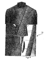
- Fig. 4 the front section of a drilling tool 1 is shown.
- the drilling tool 1 comprises a drill head 2 and a base body 3, on which the drill head 2 is fastened via a clamping screw 4.
- Fig. 1 the drilling tool 1 is shown without clamping screw 4.
- the drill head 2 comprises a drill tip 5, from which two main cutting edges 6 originate, to which an open surface 7 adjoins opposite to the cutting direction of the main cutting edges 6.
- the free surface 7 consists of two partial surfaces 7a and 7b, wherein the partial surface 7b has a larger clearance angle has as the part surface 7a.
- flutes 8 are provided, which are each delimited by a secondary cutting edge 9 on the circumferential outer side of the drilling tool 1.
- the flutes 8 extend spirally and continued in the base body 3.
- a dovetail piece 10 is formed on the drill head 2 with flanks 11, 12 which converge towards the drill tip 5.
- the drill head 2 has abutment surfaces 14, 15 which lie in a plane perpendicular to the longitudinal axis of the drilling tool 1 and are matched to matching abutment surfaces 16, 17 on flank sections 18, 19 of the recess 13. Accordingly, the stop surfaces 16, 17 lie in a plane which extends perpendicular to the longitudinal axis of the drilling tool 1 itself. The stop surfaces 16, 17 form the foremost end-side end region of the flank sections 18, 19 of the recess 13.
- the drill head 2 can be inserted laterally along the flanks 11, 12 of the dovetail piece 10 into the recess 13.
- the dovetail piece 10 is already centered in a direction transverse to the flanks 11, 12 on the axis of the drilling tool 1.
- a centering by screwing the clamping screw 4 by a middle section of the clamping screw 4 meets precisely machined side walls 20, 21 of a channel-shaped recess 23 in the dovetail piece 10.
- the clamping screw 4 can rotate freely in the recess 23, however, has a thread that can be screwed into a matching threaded hole in flank portion 19 of the recess 13.
- flank sections 18 and 19 elastically deform during clamping with the clamping screw 4, a slot 25 running transversely through the base body 3 is formed in a base 24 of the recess 13. This increases the effective length of the flank sections to provide greater elasticity.
- FIG. 5 is a cutting head 2 accordingly FIG. 1 which includes a dovetail-shaped portion 10 which is inserted into the associated dovetail guide of the holder 3.
- a clamping screw 4a is arranged in the groove-shaped recess 23.
- the screw connection comprises a clamping screw 4a, which is screwed at its free end with a threaded nut 28. Screwing the clamping screw 4a in the threaded nut 28 biases the two flank portions 18 and 19 of the holder 3 (see FIG. 1 ) against each other.
- the dovetail-shaped portion 10 of the cutting head 2 is pressed and fixed in the dovetail recess 13 in the direction of the holder 3.
- the threaded nut 28 has on its side facing the thread of the clamping screw 4 a lateral surface an inclined surface 29 which is associated with an inclined surface in the holder 3.
- the clamping screw 4a has on its lateral surface a recess or a taper 26, which provides a flow of coolant, when the holder 3 is additionally formed with a coolant channel for the passage of coolant.
- a recess 27 is provided in the region of the recess or taper 26, which creates a connection from the recess or taper 26 of the clamping screw 4a to an emerging in the free surface 7 opening 33. Due to the dovetail-shaped region 10, the recess 27 in the cutting head in the region of the flanks 11 and 12 in the manner of a recessed groove 34 is formed.
- FIG. 6 is shown an intermediate piece 31, which in its shape the end-side connection region of a in FIG. 1 shown holders 3 for receiving a cutting head 2 is modeled.
- the intermediate piece 31 forms an adapter between the cutting head 2 and the holder 3, if it is formed for example as a hollow body. It is conceivable that the intermediate piece 31, for example, on the surface 3 directed to the holder surface has a radial shoulder, which is provided for insertion of the intermediate piece 31 in the holder 3.
- Such a tool is suitable for example for the production of deep bores.
- a cutting head 2 is shown, which is designed as a plate-like cutting insert 32.
- the cutting insert 32 has matching with the dovetail recess 13 side surfaces 30a and 30b.
- the cutting head 2 dispenses with laterally protruding stop surfaces, such as the Stop surfaces on the end faces 16 and 17 of the cutting head 2.
- a stop is z. B. at the bottom of the dovetail recess on the stop surfaces 50 instead.
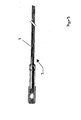
- FIG. 9 a holder 3 is shown, which comprises a hollow body portion is formed and on the lateral surface has a rectilinear flute 8.
- An arrangement of a cutting head 2 and a cutting insert 32 is according to the invention with the intermediate piece 31 FIG. 6 possible.
- ⁇ U> REFERENCE LIST ⁇ / u> 1 drilling 2 cutting head 3 holder 4 screw 4a screw 5 drill 6 main cutting edge 7 open space 7a subarea 7b subarea 8th flute 9 Besides cutting 10 dovetailed area 11 flank 12 flank 13 Dovetail recess 14 Stop surface, front side 15 Stop surface, front side 16 front 17 front 18 flank section 19 flank section 20 Side wall 21 Side wall 23 recess 24 ground 25 slot 26 recess 27 recess 28 threaded nut 29 sloping surface 30a side surface 30b side surface 31 connecting piece 32 cutting insert 33 opening 50 stop surface
Landscapes
- Engineering & Computer Science (AREA)
- Mechanical Engineering (AREA)
- Drilling Tools (AREA)
Description
Die Erfindung betrifft ein drehantreibbares Werkzeug zur spanabtragenden Bearbeitung mit einem Schneidorgan nach dem Oberbegriff des Anspruchs 1, wie es aus der
Aus der deutschen Offenlegungsschrift
In einer Ausführungsform ist der Schneideinsatz im Querschnitt trapezförmig.In one embodiment, the cutting insert is trapezoidal in cross-section.
Die
Der Erfindung liegt die Aufgabe zugrunde, ein Werkzeug der einleitend beschriebenen Art bereitzustellen, bei welchem sich die Schneiden bei vergleichsweise einfacherem Aufbau austauschen lassen und wobei insbesondere eine Erhöhung der mechanischen Stabilität des Werkzeugs erziehlt werden kann.The invention has for its object to provide a tool of the type described in the introduction, in which the blades can be replaced with a comparatively simpler structure and in particular an increase in the mechanical stability of the tool can be erziehlt.
Diese Aufgabe wird durch die Merkmale des Anspruchs 1 gelöst.This object is solved by the features of
In den abhängigen Ansprüchen sind vorteilhafte und zweckmäßige Weiterbildungen der Erfindung angegeben.In the dependent claims advantageous and expedient developments of the invention are given.
Die Erfindung geht von einem Werkzeug zur spanabtragenden Bearbeitung, insbesondere Bohrwerkzeug zur beispielsweise Metallbearbeitung mit einem Schneidorgan und einem Halter mit einem Schaftteil aus, wobei am Schneidorgan zumindest eine Schneide und ein schwalbenschwanzförmiger Bereich und am Halter eine dazu passende Schwalbenschwanz-Ausnehmung ausgebildet ist, wobei das Schneidorgan und die passende Schwalbenschwanz-Ausbildung derart aufeinander abgestimmt sind, dass das Schneidorgan nur lateral zu einer Längsachse des Halters in den Halter eingeschoben werden kann, wobei zur Fixierung des Schneidorgans gegenüberliegende Flankenabschnitte der Schwalbenschwanz-Ausnehmung, zwischen welchen der schwalbenschwanzförmige Bereich bestimmungsgemäß angeordnet ist; über eine Schraubenverbindung im Halter aufeinander zu bewegbar sind und wobei das Schneidorgan beim Fixieren durch die Schraubverbindung eine Kraft in axialer Richtung erfährt.The invention is based on a tool for chip-removing machining, in particular a drilling tool for metalworking, for example, with a cutting member and a holder with a shank part, wherein at least one cutting edge and a dovetail-shaped region on the cutting member and a matching dovetail recess is formed on the holder Cutting member and the matching dovetail design are coordinated so that the cutting member can be inserted only laterally to a longitudinal axis of the holder in the holder, wherein for fixing the cutting member opposite flank portions of the dovetail recess, between which the dovetail-shaped portion is arranged as intended; can be moved towards each other via a screw connection in the holder and wherein the cutting member undergoes a force in the axial direction during fixing by the screw connection.
Der Kern der Erfindung liegt nun darin, dass das Schneidorgan ein Schneidkopf ist und dass die Kraft in axialer Richtung ausschließlich durch den schwalbenschwanzförmigen Bereich in Zusammenwirkung der Schwalbenschwanz-Ausnehmung im Halter bereitgestellt ist. Diese Vorgehensweise hat den Vorteil, dass auf einfache Weise ein Schneidkopf, der z. B. wie ein üblicher Bohrerkopf ausgebildet ist, sich mit einem Halter verbinden lässt, der den restlichen Bohrergrundkörper bildet. Damit ist man in der Bohrergeometrie nicht beschränkt. Es ist insbesondere möglich, alle üblichen Bohrergeometrien zu realisieren. Insbesondere ist vorgesehen, dass der schwalbenschwanzförmige Bereich als Fortsatz aus der stirnseitigen Anschlagfläche herausragt. Beispielsweise sind beidseitig des schwalbenschwanzförmigen Fortsatzes Anschlagflächen ausgebildet, die in einer Ebene liegen, aus welcher der Fortsatz herausragt.The essence of the invention lies in the fact that the cutting member is a cutting head and that the force is provided in the axial direction exclusively by the dovetail-shaped portion in cooperation of the dovetail recess in the holder. This approach has the advantage that in a simple way a cutting head, the z. B. as a conventional drill head is formed, can be connected to a holder, which forms the rest of the drill body. This is not limited in the drill geometry. In particular, it is possible to realize all the usual drill geometries. In particular, it is provided that the dovetail-shaped region protrudes as an extension from the end-side stop surface. For example, on both sides of the dovetail-shaped extension stop surfaces are formed, which lie in a plane from which protrudes the extension.
Insbesondere lässt sich der Bohrerkopf mit Schneiden und Spannuten völlig herkömmlich, z. B. durch Schleifen, herstellen.In particular, the drill head can be completely conventional with cutting and flutes, z. B. by grinding.
Durch die Positionierung in axialer Richtung nur durch die Schwalbenschwanzgeometrie ist es nicht erforderlich in diese Ausrichtung zum Beispiel Befestigungsöffnungen aufeinander abzustimmen.Due to the positioning in the axial direction only by the dovetail geometry, it is not necessary to coordinate in this orientation, for example mounting holes on each other.
In einer bevorzugten Ausgestaltung der Erfindung ist vorgesehen, dass der schwalbenschwanzförmige Bereich an einer stirnseitigen Anschlagfläche des Schneidkopfes anschließt. Bei einer solchen Ausführungsform wird der Schneidkopf in axialer Richtung vorzugsweise nicht gegen einen Grund der Schwalbenschwanz-Ausnehmung positioniert, sondern nur gegen diesen stirnseitigen Anschlag. Die damit näher zu den Schneiden hin rückende Verbindungsstelle zwischen Kopf und Halter hat den Vorteil einer höheren Stabilität des Werkzeugs. Außerdem sind die dazu passenden Anschlagflächen am Halter leicht zugänglich, insbesondere für eine Bearbeitung.In a preferred embodiment of the invention, it is provided that the dovetail-shaped region adjoins an end-face stop surface of the cutting head. In such an embodiment, the cutting head in the axial direction is preferably not positioned against a bottom of the dovetail recess, but only against this end stop. The thus closer to the cutting back towards the junction between the head and holder has the advantage of greater stability of the tool. In addition, the matching stop surfaces on the holder are easily accessible, especially for editing.
In Bezug auf den Halter ist es bevorzugt, dass die stirnseitige Anschlagfläche dem Endbereich der Flankenabschnitte, insbesondere dem vordersten stirnseitigen Endbereich der Flankenabschnitte gegenüberliegt. Eine solche Ausgestaltung lässt sich rationell herstellen und vergleichsweise einfach auf die Schwalbenschwanz-Ausnehmung im Halter abstimmen.With respect to the holder, it is preferred that the end-face abutment surface is opposite the end region of the flank sections, in particular the foremost end-side end region of the flank sections. Such an embodiment can be produced efficiently and tuned comparatively easily to the dovetail recess in the holder.
Im Weiteren ist es bevorzugt, wenn der schwalbenschwanzförmige Bereich an der stirnseitigen Anschlagfläche derart anschließt, dass in einem in die Schwalbenschwanz-Ausnehmung eingesetzten Zustand ein Drehmoment beim Bohren nur über den schwalbenschwanzförmigen Bereich übertragen wird.
In einer überdies bevorzugten Ausgestaltung der Erfindung ist der schwalbenschwanzförmige Bereich auf die Schwalbenschwanz-Ausnehmung derart abgestimmt, dass die Kraft in axialer Richtung im Spannzustand des Schneidkopfes die stirnseitige Anschlagfläche gegen jeweils eine Stirnseite der Flankenabschnitte der Schwalbenschwanz-Ausnehmung presst. Hierdurch lässt sich eine besonders steife Verbindung zwischen dem Schneidkopf und dem Halter erreichen. Dabei kann vor dem Verspannen vorzugsweise ein Spiel in axialer Richtung im eingeschobenen Zustand zwischen den Anschlagflächen am Schneidkopf und den Stirnseiten, insbesondere den jeweils vordersten Stirnseiten der Flankenabschnitte der Schwalbenschwanz-Ausnehmung bestehen. Beim Verspannen der Flankenabschnitte durch die Schraubverbindung wird dann der Schneidkopf gegen die Flankenabschnitte gezogen, so dass das Spiel verschwindet und der Schneidkopfsatz auf den Flankenabschnitten anliegt, wodurch sich eine definierte steife Befestigung des Schneidkopfs am Halter erzielen lässt.Furthermore, it is preferred if the dovetail-shaped region adjoins the front-side stop surface in such a way that in a state inserted into the dovetail recess a torque is transmitted during drilling only via the dovetail-shaped region.
In a further preferred embodiment of the invention, the dovetail-shaped region is tuned to the dovetail recess such that the force in the axial direction in the clamping state of the cutting head presses the end-face abutment surface against one end face of the flank sections of the dovetail recess. This makes it possible to achieve a particularly rigid connection between the cutting head and the holder. In this case, prior to bracing preferably a game in the axial direction in the inserted state between the abutment surfaces on the cutting head and the end faces, in particular the respective foremost end sides of the flank portions of the dovetail recess exist. When clamping the flank sections through the screw connection, the cutting head is then pulled against the flank sections, so that the play disappears and the cutting head set lies against the flank sections, whereby a defined rigid attachment of the cutting head to the holder can be achieved.
In einem überdies bevorzugten Ausführungsbeispiel der Erfindung ist im Schwalbenschwanzbereich eine Ausnehmung auf eine im Halter geführte Schraube der Schraubverbindung in einer Weise abgestimmt, dass neben einer Lagefixierung durch einen Einschub des schwalbenschwanzförmigen Bereichs auch eine Zentrierung in Einschubrichtung des Schneidkopfes über die Schraube der Schraubenverbindung stattfindet. Durch diese Maßnahme lässt sich bei vergleichsweise einfacher Geometrie der Verbindung zwischen Schneidkopf und Halter lediglich durch Einschieben des Schneidkopfes und Anziehen der Schraube eine positionsgenaue Lagefixierung des Schneidkopfs zur Drehachse des Halters erreichen, die darüber hinaus eine hohe Stabilität aufweist.In another preferred embodiment of the invention, a recess in the dovetail area is matched to a screw of the screw connection guided in the holder in such a way that, in addition to a positional fixation by an insertion of the dovetail-shaped area, a centering in the direction of insertion of the cutting head over the Screw of the screw connection takes place. By this measure can be achieved with a comparatively simple geometry of the connection between the cutting head and holder only by inserting the cutting head and tightening the screw positionally accurate positional fixation of the cutting head to the axis of rotation of the holder, which also has a high stability.
Der Schneidkopf kann aus Vollhartmetall, insbesondere vollständig aus Vollhartmetall bestehen. Im Gegensatz dazu kann der Halter mit Schaftteil aus Stahl, z. B. HSS oder Werkzeugstahl gefertigt sein. Damit lässt sich eine Kostenoptimierung des Werkzeugs bei hoher Verschleißbeständigkeit erreichen. Es ist auch denkbar, dass der Schneidkopf aus HSS oder einem keramischen Schneidstoff besteht.The cutting head can be made of solid carbide, in particular completely made of solid carbide. In contrast, the holder with shank part made of steel, z. B. HSS or tool steel. This can be a cost optimization of the tool achieve high wear resistance. It is also conceivable that the cutting head consists of HSS or a ceramic cutting material.
Damit die Flankenabschnitte der Schwalbenschwanz-Ausnehmung beim Verspannen sich in gewünschter Weise aufeinander zu bewegen, wird im Weiteren vorgeschlagen, dass am Boden der Schwalbenschwanz-Ausnehmung ein Schlitz in axialer Richtung ausgebildet ist, der den Halter in lateraler Richtung in zwei Teile trennt. Damit lässt sich auch sicherstellen, dass eine Bewegung der Flankenabschnitte beim Verspannen des schwalbenschwanzförmigen Bereichs in einem elastischen Bereich bleibt.In order for the flank sections of the dovetail recess to move toward one another in a desired manner during clamping, it is further suggested that a slot is formed in the axial direction at the bottom of the dovetail recess, which separates the holder in a lateral direction into two parts. In this way, it is also possible to ensure that a movement of the flank sections during the tightening of the dovetail-shaped region remains in an elastic region.
Außerdem ist es bevorzugt, wenn die Kontur des Halters mit Spannuten sich im Wesentlichen im Schneidkopf fortsetzt. Durch diese Maßnahme wird z. B. die Spanabfuhr vom Schneidkopf in den Bereich des Halters auch an der Verbindungsstelle von Schneidkopf und Halter nicht gestört. Vorzugsweise sind am Schneidkopf entlang einer Spannut Nebenschneiden ausgebildet, die eine exakte Führung des Werkzeugs sicherstellen.Moreover, it is preferred if the contour of the holder with flutes substantially continues in the cutting head. By this measure z. B. the chip removal from the cutting head in the region of the holder and not disturbed at the junction of the cutting head and holder. Preferably, secondary cutting edges are formed on the cutting head along a flute, which ensure an exact guidance of the tool.
In einer besonders bevorzugten Ausgestaltung der Erfindung ist die Ausnehmung im schwalbenschwanzförmigen Bereich rinnenförmig ausgeführt. Eine solche Ausgestaltung einer Schraubenausnehmung lässt sich vergleichsweise einfach in den schwalbenschwanzförmigen Bereich einbringen. Die rinnenförmige Ausnehmung kann z. B. als Führungsrinne in einer Weise ausgebildet sein, dass seitliche Wandungsabschnitte der Rinne auf einen Schraubenbereich der Spanschraube so abgestimmt sind, dass beim Eindrehen der Schraube in den Halter automatisch eine Zentrierung in Einschubrichtung des Schneidkopfes auf eine Drehachse stattfindet.In a particularly preferred embodiment of the invention, the recess in the dovetail-shaped region is designed channel-shaped. Such a configuration of a screw recess can be comparatively easy in the Insert dovetail-shaped area. The gutter-shaped recess may, for. B. be formed as a guide groove in a way that lateral wall sections of the channel are tuned to a screw portion of the clamping screw so that automatically takes place when screwing the screw into the holder centering in the direction of insertion of the cutting head on a rotation axis.
Überdies ist in einer weiteren Ausgestaltung der Erfindung ein Kühlkanal im Halter vorgesehen, der an einer Stirnseite des Halters, die zum Schneidkopf zeigt, eine Öffnung aufweist. Der Kühlkanal kann geradlinig oder spiralförmig, axial oder außermittig im Halter verlaufen. Es ist auch denkbar, dass zwei Kühlkanäle im Halter angeordnet sind, die beispielsweise parallel und/oder spiralförmig verlaufen. Die Kühlkanäle können sich im Schneidkopf fortsetzen.Moreover, in a further embodiment of the invention, a cooling channel is provided in the holder, which has an opening at an end face of the holder which faces the cutting head. The cooling channel may be rectilinear or spiral, axially or eccentrically in the holder. It is also conceivable that two cooling channels are arranged in the holder, which run, for example, parallel and / or spiral. The cooling channels can continue in the cutting head.
Weiterhin weist in einer bevorzugten Ausgestaltung der Erfindung die Mantelfläche der Schraube eine Aussparung oder eine Verjüngung auf. Die zum Beispiel in einer rinnenförmigen Ausnehmung des Schneidkopfes angeordnete Schraube ist vorzugsweise mit einer Verjüngung versehen, die vollumfänglich im schwalbenschwanzförmigen Bereich vorgesehen ist. Diese Verjüngung ermöglicht ein vorzugsweise freies Fließen von Kühlmittel vom Kühlkanal des Halters über die Spannschraube zum Schneidkopf. Die Anzahl der Verjüngungen oder der Ausnehmungen ist beispielsweise der Kühlmittelkanäle im Halter und/oder der Schneiden des Schneidkopfes angepasst.
Damit kann zum Beispiel jede Schneide mit Kühlmittel versorgt werden, durch z. B. einen oder mehrere Kühlkanäle im Schneidkopf.Furthermore, in a preferred embodiment of the invention, the lateral surface of the screw on a recess or a taper. The screw arranged, for example, in a groove-shaped recess of the cutting head is preferably provided with a taper, which is provided completely in the dovetail-shaped area. This taper allows a preferably free flow of coolant from the cooling channel of the holder via the clamping screw to the cutting head. The number of tapers or recesses, for example, the coolant channels in the holder and / or the cutting of the cutting head adapted.
Thus, for example, each blade can be supplied with coolant, by z. B. one or more cooling channels in the cutting head.
Die Kühlkanäle können auch so angeordnet sein, dass diese an einer Spannschraube vorbeiführen, ohne dass diese verjüngt werden muss.The cooling channels can also be arranged so that they lead past a clamping screw, without having to be tapered.
In einer weiteren Ausgestaltung der Erfindung ist vorgesehen, dass im Schneidkopf im Bereich der Aussparung bzw. der Verjüngung eine Ausnehmung vorgesehen ist. Die Ausnehmung verläuft beispielsweise beginnend von der Verjüngung bzw. Ausnehmung auf der Schraube in Richtung einer Freifläche hinter eine Schneide des Schneidkopfes und mündet dort in eine Öffnung. Das Kühlmittel kann ausgehend von dem Kühlmittelkanal im Halter über die Verjüngung bzw. Ausnehmung auf der Schraube in die Ausnehmung im Schneidkopf bis hin zur Öffnung auf der Freifläche an die Schneidfläche fließen.In a further embodiment of the invention it is provided that a recess is provided in the cutting head in the region of the recess or the taper. The recess For example, starting from the taper or recess on the screw in the direction of an open space behind a cutting edge of the cutting head and there opens into an opening. The coolant can flow from the coolant channel in the holder via the taper or recess on the screw in the recess in the cutting head to the opening on the free surface of the cutting surface.
Überdies ist in einer weiteren Ausgestaltung der Erfindung der Halter dazu ausgelegt, die Spannschraube an ihrem freien Ende mit einer Gewindemutter zu spannen. Die Gewindemutter ist beispielsweise im Halter versenkt angeordnet. Bei der Verwendung einer Gewindemutter kann im Halter auf die Anordnung eines Innengewindes zur Befestigung der Spannschraube verzichtet werden.Moreover, in a further embodiment of the invention, the holder is adapted to tension the clamping screw at its free end with a threaded nut. The nut is sunk, for example, in the holder. When using a threaded nut can be dispensed with in the holder on the arrangement of an internal thread for fixing the clamping screw.
Außerdem ist es bevorzugt, dass an der Gewindemutter eine Schrägfläche vorgesehen ist, die in einer entsprechenden Schrägfläche des Halters zugeordnet ist. Beim Einschrauben der Spannschraube in die Gewindemutter kann der Schneidkopf aufgrund der ineinander greifenden Schrägflächen zusätzlich zentriert werden.In addition, it is preferred that an oblique surface is provided on the threaded nut, which is assigned in a corresponding inclined surface of the holder. When screwing the clamping screw into the threaded nut, the cutting head can be additionally centered due to the interlocking inclined surfaces.
In einem außerdem bevorzugten Ausführungsbeispiel ist der Schneidkopf plattenartig mit zur Schwalbenschwanz-Ausnehmung passenden Seitenflächen ausgebildet. Der Schneidkopf ist als Schneideinsatz mit einem Schwalbenschwanz vorgesehen, der auf zusätzliche Anschlagflächen zur Auflage an seitlichen Stirnflachen des Halters neben der Schwalbenschwanz-Ausnehmung verzichtet.In a further preferred embodiment, the cutting head is plate-like with formed to the dovetail recess side surfaces. The cutting head is provided as a cutting insert with a dovetail, which dispenses with additional stop surfaces for resting on lateral end faces of the holder in addition to the dovetail recess.
Überdies ist in einem weiteren Ausführungsbeispiel vorgesehen, dass das Werkzeug mit einem Halter mit einer geradlinig verlaufenden Spannut ausgebildet ist. Ein entsprechendes Werkzeug kann zum Beispiel für die Erzeugung einer Tiefenbohrung eingesetzt werden. Der Halter ist vorzugsweise ein Höhlkörper, der mit einem am dem Spannschaft gegenüberliegenden Ende angeordneten Schneidkopf mit mindestens einer Schneide verbunden ist.Moreover, it is provided in a further embodiment that the tool is formed with a holder with a rectilinear chip flute. A corresponding tool can be used for example for the production of a deep hole. The holder is preferably a hollow body which is connected to at least one cutting edge with a cutting head arranged at the opposite end of the clamping shaft.
Außerdem ist in einer überdies bevorzugten Ausgestaltung der Erfindung vorgesehen, dass zur Anordnung des Schneidkopfes am Halter ein Zwischenstück vorgesehen ist. Das Zwischenstück weist eine Schwalbenschwanzführung zur Aufnahme des Schneidkopfes bzw. eines Schneideinsatzes auf. Das freie Ende des Zwischenstücks ist beispielsweise mit einem Absatz versehen, der in den als Hohlkörper ausgebildeten Halter befestigt werden kann. Vorzugsweise ist das Zwischenstück aus einem HSS-Material (Hochleistungs-Schnellschnitt-Stahl) gebildet.In addition, it is provided in a further preferred embodiment of the invention, that for the arrangement of the cutting head on the holder an intermediate piece is provided. The intermediate piece has a dovetail guide for receiving the cutting head or a cutting insert. The free end of the intermediate piece is provided, for example, with a shoulder which can be fastened in the holder designed as a hollow body. Preferably, the intermediate piece is formed from an HSS material (high-speed hot-cut steel).
In diesem Zusammenhang ist es bevorzugt, dass zur Durchleitung von Kühlmittel das Zwischenstück wenigstens einen Kühlkanal aufweist. Dadurch ist eine gezielte Führung eines Kühlmittels über den Halter bis hin zur Schneide des Schneidkopfes bzw. des Schneideinsatzes möglich.In this context, it is preferred that for the passage of coolant, the intermediate piece has at least one cooling channel. As a result, targeted guidance of a coolant over the holder up to the cutting edge of the cutting head or of the cutting insert is possible.
Ausführungsbeispiele der Erfindung sind in den Zeichnungen dargestellt und werden nachstehend unter Angabe weiterer Vorteile und Einzelheiten näher erläutert.Embodiments of the invention are illustrated in the drawings and are explained in more detail below, giving further advantages and details.
Es zeigen:
Figur 1- den vorderen Teil inklusive Schneidkopf eines erfindungsgemäßen Bohrwerkzeugs in einer Seitenansicht,
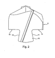
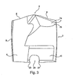
Figuren 2 und 3- lediglich den Schneidkopf eines Bohrwerkzeugs in einer Seitenansicht längs zu einer Einschubrichtung eines Schwalbenschwanzfortsatzes (
Fig. 2 ) sowie quer dazu (Fig. 3 ), - Figur 4
- in einer dreidimensionalen Darstellung den vorderen Teil eines Bohrwerkzeugs mit Schneidkopf, Befestigungsschraube und transparent dargestelltem Grundkörper,
Figur 5- einen erfindungsgemäßen Schneidkopf nach
Figur 1 mit Spannschraube mit Gewindemutter und Kühlmittelführung, - Figur 6
- ein Zwischenstück in dreidimensionaler Darstellung,
- Figuren 7 und 8
- einen als Schneideinsatz ausgebildeten Schneidkörper nach
Figur 1 in Drauf- und Seitenansicht und Figur 9- einen Halter mit geradliniger Spannut in dreidimensionaler Darstellung.
- FIG. 1
- the front part including cutting head of a drilling tool according to the invention in a side view,
- FIGS. 2 and 3
- only the cutting head of a drilling tool in a side view along an insertion direction of a dovetail extension (
Fig. 2 ) as well as across (Fig. 3 ) - FIG. 4
- in a three-dimensional representation of the front part of a drilling tool with cutting head, mounting screw and transparently represented basic body,
- FIG. 5
- a cutting head according to the invention
FIG. 1 with clamping screw with threaded nut and coolant guide, - FIG. 6
- an intermediate piece in three-dimensional representation,
- FIGS. 7 and 8
- a designed as a cutting insert after cutting body
FIG. 1 in top and side view and - FIG. 9
- a holder with straight flute in three-dimensional representation.
In
Details zum Schneidkopf 2 sind insbesondere aus den
In
Der Bohrerkopf 2 umfasst eine Bohrerspitze 5, von welcher zwei Hauptschneiden 6 ausgehen, an welche sich entgegen der Schneidrichtung der Hauptschneiden 6 jeweils eine Freifläche 7 anschließt. Die Freifläche 7 besteht aus zwei Teilflächen 7a und 7b, wobei die Teilfläche 7b einen größeren Freiwinkel aufweist als die Teilfläche 7a. Des Weiteren sind Spannuten 8 vorgesehen, die an der umfänglichen Außenseite des Bohrwerkzeugs 1 jeweils von einer Nebenschneide 9 begrenzt ist.The
Die Spannuten 8 verlaufen spiralförmig und setzten sich im Grundkörper 3 fort.The
Am Bohrerkopf 2 ist ein Schwalbenschwanzstück 10 ausgebildet mit sich zur Bohrerspitze 5 hin aufeinander zulaufenden Flanken 11, 12.A
Dazu passend ist im Grundkörper 3 eine Ausnehmung 13 vorgesehen.Matching a
Der Bohrerkopf 2 weist Anschlagflächen 14, 15 auf, die in einer Ebene senkrecht zur Längsachse des Bohrwerkzeugs 1 liegen und auf dazu passende Anschlagflächen 16, 17 an Flankenabschnitten 18, 19 der Ausnehmung 13 abgestimmt sind. Dementsprechend liegen auch die Anschlagflächen 16, 17 in einer Ebene, die senkrecht zur Längsachse des Bohrwerkzeugs 1 sich erstreckt. Die Anschlagflächen 16, 17 bilden den vordersten stirnseitigen Endbereich der Flankenabschnitte 18, 19 der Ausnehmung 13.The
Damit lässt sich der Bohrerkopf 2 seitlich entlang der Flanken 11, 12 des Schwalbenschwanzstücks 10 in die Ausnehmung 13 einschieben. Auf diese Weise wird das Schwalbenschwanzstück 10 bereits in einer Richtung quer zu den Flanken 11, 12 auf die Achse des Bohrwerkzeugs 1 zentriert.Thus, the
In Einschubrichtung erfolgt eine Zentrierung durch Einschrauben der Spannschraube 4, indem ein mittlerer Abschnitt der Spannschraube 4 auf präzise gearbeitete Seitenwände 20, 21 einer rinnenförmigen Ausnehmung 23 im Schwalbenschwanzstück 10 trifft.In the insertion direction, a centering by screwing the clamping screw 4 by a middle section of the clamping screw 4 meets precisely machined
Die Spannschraube 4 kann sich in der Ausnehmung 23 frei drehen besitzt jedoch ein Gewinde, das sich in eine dazu passende Gewindebohrung in Flankenabschnitt 19 der Ausnehmung 13 einschrauben lässt.The clamping screw 4 can rotate freely in the
Beim Einschrauben zentriert sich der Bohrerkopf 2 in Einschubrichtung des Schwalbenschwanzstücks 10 automatisch. Beim vollständigen Anziehen der Spanschrauben 4 wird durch die Keilwirkung beim Zusammenspiel des Schwalbenschwanzstücks 10 mit den Seitenwänden der Ausnehmung 13 der Bohrerkopf 2 axial in Richtung des Grundkörpers 3 gezogen, so dass die Anschlagflächen 14 und 16 bzw. 15 und 17 aufeinander gepresst werden.When screwing the
Damit sich die Flankenabschnitte 18 und 19 beim Verspannen mit der Spanschraube 4 elastisch verformen ist in einem Boden 24 der Ausnehmung 13 ein quer durch den Grundkörper 3 laufender Schlitz 25 ausgebildet. Dadurch wird die effektive Länge der Flankenabschnitte vergrößert, um eine höhere Elastizität bereitzustellen.So that the
In
Im schwalbenschwanzförmigen Bereich 10 ist in der rinnenförmigen Ausnehmung 23 eine Spannschraube 4a angeordnet.In the dovetail-shaped
Die Schraubenverbindung umfasst eine Spannschraube 4a, die an ihrem freien Ende mit einer Gewindemutter 28 verschraubt ist. Ein Einschrauben der Spannschraube 4a in die Gewindemutter 28 spannt die beiden Flankenabschnitte 18 und 19 des Halters 3 (siehe
Die Spannschraube 4a weist auf ihrer Mantelfläche eine Aussparung oder eine Verjüngung 26 auf, welche ein Durchfließen von Kühlmittel vorsieht, wenn der Halter 3 zusätzlich mit einem Kühlmittelkanal zur Durchleitung von Kühlmittel ausgebildet ist.The clamping screw 4a has on its lateral surface a recess or a
Im Schneidkopf 2 ist im Bereich der Aussparung bzw. Verjüngung 26 eine Ausnehmung 27 vorgesehen, die eine Verbindung von der Aussparung bzw. Verjüngung 26 der Spannschraube 4a bis hin zu einer in der Freifläche 7 austretenden Öffnung 33 erzeugt. Aufgrund des schwalbenschwanzförmigen Bereichs 10 ist die Ausnehmung 27 im Schneidkopf im Bereich der Flanken 11 und 12 in der Art einer Ausnehmungs-Rinne 34 ausgebildet.In the cutting
In
In den
In
Claims (9)
- A rotatably drivable cutting tool for machining, in particular a drilling tool with a cutting member (2) and a holder (3) with a shank portion, wherein on the cutting member (2) at least one cutting edge (6) and a dovetail-shaped portion (10) and on the holder (3) a matching dovetail recess (13) are formed, wherein the cutting member (2) and the matching dovetail recess (13) are matched to one another such that the cutting member (2) can be slid into the holder (3) only laterally to a longitudinal axis of the holder (3), wherein for fixating the cutting member (2) opposing flank sections (18, 19) of the dovetail recess (10), between which the dovetail-shaped portion (10) is positioned as intended, are movable towards each other via a screw connection (4) in the holder (3) and wherein the cutting member (2) in the fixating receives a force in the axial direction by the screw connection (4), wherein the cutting member is a cutting head (2) and the force in axial direction is provided solely by the dovetail-shaped portion (10) in cooperation of the dovetail recess (13) in the holder (3), characterized in that the dovetail-shaped portion (10) protrudes as an extension directly from the end abutment face (14, 15).
- The cutting tool according to claim 1, characterized in that the dovetail-shaped portion (10) adjoins a front abutment surface of the cutting head (2).
- The cutting tool according to any one of the preceding claims, characterized in that the dovetail-shaped portion (10) is adapted to the dovetail recess (13) in such a manner that in the clamped state the force in axial direction presses the end abutment face (14, 15) against end faces (16, 17) of the flank sections (18, 19) of the dovetail recess (13).
- The cutting tool according to any one of the preceding claims, characterized in that in the dovetail-shaped portion (10) a recess (23) is adapted to a screw (4) of the screw connection, which is guided in the holder (3), in such a way that in addition to fixing the position by an insertion of the dovetail into the dovetail recess (13) a centering in inserting direction of the cutting head (2) to the axis of rotation of the tool takes place via the screw (4a) of the screw connection (4).
- The cutting tool according to claim 4, characterized in that the recess (23) for a clamping screw (4a) in the dovetail-shaped portion (10) is groove-shaped.
- The cutting tool according to any one of the preceding claims, characterized in that in the holder (3) at least one cooling channel is provided, which has an opening on an end face of the holder (3) facing the cutting head (2).
- The cutting tool according to any one of the preceding claims, characterized in that the outer surface of the screw (4a) has an indentation or a taper (26).
- The cutting tool according to claim 7, characterized in that in the cutting head (2) in the region of the indentation or taper (26) a recess (27) is provided.
- The cutting tool according to any one of the preceding claims, characterized in that the cutting head (2) is formed plate-like with side faces (30a, 30b) matching the dovetail recess (13).
Applications Claiming Priority (2)
| Application Number | Priority Date | Filing Date | Title |
|---|---|---|---|
| DE102008020963 | 2008-04-25 | ||
| PCT/DE2009/000536 WO2009129792A2 (en) | 2008-04-25 | 2009-04-22 | Rotary-driven tool for cutting machining with a cutting body |
Publications (2)
| Publication Number | Publication Date |
|---|---|
| EP2280795A2 EP2280795A2 (en) | 2011-02-09 |
| EP2280795B1 true EP2280795B1 (en) | 2013-07-17 |
Family
ID=41017101
Family Applications (1)
| Application Number | Title | Priority Date | Filing Date |
|---|---|---|---|
| EP09734628.2A Active EP2280795B1 (en) | 2008-04-25 | 2009-04-22 | Rotary-driven tool for cutting machining with a cutting body |
Country Status (7)
| Country | Link |
|---|---|
| US (1) | US8992136B2 (en) |
| EP (1) | EP2280795B1 (en) |
| JP (1) | JP5450594B2 (en) |
| KR (1) | KR20100137552A (en) |
| CN (1) | CN102015171A (en) |
| DE (1) | DE102009018327A1 (en) |
| WO (1) | WO2009129792A2 (en) |
Families Citing this family (30)
| Publication number | Priority date | Publication date | Assignee | Title |
|---|---|---|---|---|
| IL195804A (en) * | 2008-12-09 | 2012-12-31 | Iscar Ltd | Cutting tool having releasably mounted self-clamping cutting head |
| EP2517812B1 (en) * | 2011-04-05 | 2014-12-31 | SECO TOOLS AB (publ) | A cutting head comprising a drill tip and a drill having such a cutting head |
| CN102303152A (en) * | 2011-08-16 | 2012-01-04 | 朱世照 | Auger drill with replaceable blade |
| DE102012200690B4 (en) * | 2012-01-18 | 2021-06-17 | Kennametal Inc. | Rotary tool and cutting head for such a rotary tool |
| US8876446B2 (en) * | 2012-03-28 | 2014-11-04 | Iscar, Ltd. | Cutting tool having clamping bolt provided with locking portion and cutting insert therefor |
| DE102013205889B3 (en) | 2013-04-03 | 2014-05-28 | Kennametal Inc. | Coupling structure e.g. cutting head for rotary tool e.g. drilling tool, has coupling pin with clamping faces and stop surfaces that are arranged in different dispensing areas |
| DE102013220884B4 (en) | 2013-10-15 | 2022-02-17 | Kennametal Inc. | Modular carrier tool and tool head |
| DE102014206796B4 (en) | 2014-04-08 | 2020-10-15 | Kennametal Inc. | Rotary tool, in particular drill and cutting head for such a rotary tool |
| DE102015211744B4 (en) | 2015-06-24 | 2023-07-20 | Kennametal Inc. | Rotary tool, in particular a drill, and cutting head for such a rotary tool |
| USD798921S1 (en) | 2015-10-07 | 2017-10-03 | Kennametal Inc. | Cutting head for modular drill |
| USD798922S1 (en) | 2015-10-07 | 2017-10-03 | Kennametal Inc. | Cutting head for rotary drill |
| US9937567B2 (en) | 2015-10-07 | 2018-04-10 | Kennametal Inc. | Modular drill |
| US10071430B2 (en) | 2015-10-07 | 2018-09-11 | Kennametal Inc. | Cutting head, rotary tool and support for the rotary tool and for the accommodation of the cutting head |
| CN105710398B (en) * | 2016-03-30 | 2017-10-27 | 株洲钻石切削刀具股份有限公司 | A kind of head-exchangeable cutting tool |
| DE102016205657B4 (en) * | 2016-04-06 | 2021-06-10 | Gühring KG | CHIPPING TOOL FOR DEBURRING HOLES |
| US11235397B2 (en) | 2016-12-16 | 2022-02-01 | Kennametal Inc. | Side-activated modular drill |
| DE102017205166B4 (en) | 2017-03-27 | 2021-12-09 | Kennametal Inc. | Modular rotary tool and modular tool system |
| US10207337B2 (en) | 2017-04-04 | 2019-02-19 | Kennametal Inc. | Front-loaded, side-activated modular drill |
| DE102017212054B4 (en) | 2017-07-13 | 2019-02-21 | Kennametal Inc. | Method for producing a cutting head and cutting head |
| US10799958B2 (en) | 2017-08-21 | 2020-10-13 | Kennametal Inc. | Modular rotary cutting tool |
| WO2019047433A1 (en) * | 2017-09-08 | 2019-03-14 | 浙江欣兴工具有限公司 | Rotary cutting tool with replaceable bit and rotary cutting method thereof, and bit installation method |
| DE102018206222A1 (en) | 2018-04-23 | 2019-10-24 | Gühring KG | Rotatable modular cutting tool |
| DE102019116160A1 (en) | 2018-06-20 | 2019-12-24 | Kennametal Inc. | Modular drill bit closed on the side with spring-assisted ejection |
| DE102019104686A1 (en) * | 2019-02-25 | 2020-08-27 | Index-Werke Gmbh & Co. Kg Hahn & Tessky | Tool carriers and tool holders |
| CN112077370A (en) | 2019-06-13 | 2020-12-15 | 肯纳金属印度有限公司 | Indexable drill insert |
| CN110732709B (en) * | 2019-11-12 | 2024-05-24 | 苏州沃钛工业技术有限公司 | Double-sided limiting oblique-penetrating locking replaceable drill tip |
| CN110732708B (en) * | 2019-11-12 | 2024-05-07 | 苏州沃钛工业技术有限公司 | Double-sided limiting oblique-penetrating locking bit-changing drill |
| CN113103385B (en) * | 2019-12-25 | 2024-06-07 | 三星钻石工业株式会社 | Joint material |
| US11471952B2 (en) | 2020-03-19 | 2022-10-18 | Kennametal Inc. | Cutting tool having replaceable cutting head and method of securing a replaceable cutting head |
| US11883888B2 (en) | 2021-06-28 | 2024-01-30 | Kennametal Inc. | Modular drill with enhanced bump-off capability |
Citations (1)
| Publication number | Priority date | Publication date | Assignee | Title |
|---|---|---|---|---|
| DE19543233A1 (en) * | 1995-11-07 | 1997-05-15 | Johne & Co Praezisionswerkzeug | Drill tool with interchangeable tip |
Family Cites Families (19)
| Publication number | Priority date | Publication date | Assignee | Title |
|---|---|---|---|---|
| DE3001120C2 (en) * | 1980-01-14 | 1982-08-26 | Fa. Gottlieb Gühring, 7470 Ebingen | Pointed drilling tool with exchangeable drilling knife |
| SE511429C2 (en) * | 1996-09-13 | 1999-09-27 | Seco Tools Ab | Tools, cutting part, tool body for cutting machining and method of mounting cutting part to tool body |
| DE19834635C2 (en) | 1998-07-31 | 2001-07-26 | Guehring Joerg | Drilling tool with an exchangeable cutting insert that is secured against loosening |
| JP2002113606A (en) * | 2000-10-05 | 2002-04-16 | Mitsubishi Materials Corp | Throwaway type drill |
| SE520412C2 (en) * | 2000-10-24 | 2003-07-08 | Sandvik Ab | Rotatable tool with interchangeable cutting part at the tool's cutting end free end |
| SE0103752L (en) * | 2001-11-13 | 2003-05-14 | Sandvik Ab | Rotatable tool for chip separating machining and cutting part herewith |
| JP3812480B2 (en) * | 2002-03-29 | 2006-08-23 | 三菱マテリアル株式会社 | Throw-away drill |
| JP4129192B2 (en) * | 2003-02-26 | 2008-08-06 | 京セラ株式会社 | Throwaway drill |
| US7168893B2 (en) * | 2003-03-05 | 2007-01-30 | Mitsubishi Materials Corporation | Throw-away tipped drill, throw-away tip, and drill main body |
| JP4179171B2 (en) * | 2003-03-25 | 2008-11-12 | 三菱マテリアル株式会社 | Throw-away drill and throw-away tip |
| JP4178998B2 (en) * | 2003-03-05 | 2008-11-12 | 三菱マテリアル株式会社 | Throw-away drill |
| JP2004306171A (en) * | 2003-04-03 | 2004-11-04 | Mitsubishi Materials Corp | Throw-away tipped drill and throw-away tip |
| JP4182808B2 (en) * | 2003-05-12 | 2008-11-19 | 三菱マテリアル株式会社 | Throw-away drill |
| DE10353514A1 (en) * | 2003-11-14 | 2005-06-23 | Heule, Ulf | Drilling plate with clamping attachment in a base body |
| SE528020C2 (en) | 2004-01-14 | 2006-08-08 | Sandvik Intellectual Property | Rotatable chip separating tool |
| SE527703C2 (en) * | 2004-08-19 | 2006-05-16 | Sandvik Intellectual Property | Rotatable tool and cutting head with axially serrated engaging means |
| SE0501007L (en) * | 2005-05-02 | 2006-10-03 | Sandvik Intellectual Property | Tools and removable body for tools for chip removal processing with ridge and groove-shaped coupling means |
| KR100649359B1 (en) * | 2006-01-02 | 2006-11-28 | 한국야금 주식회사 | Indexable type cutting tool |
| US8876446B2 (en) * | 2012-03-28 | 2014-11-04 | Iscar, Ltd. | Cutting tool having clamping bolt provided with locking portion and cutting insert therefor |
-
2009
- 2009-04-22 EP EP09734628.2A patent/EP2280795B1/en active Active
- 2009-04-22 KR KR1020107024514A patent/KR20100137552A/en not_active Application Discontinuation
- 2009-04-22 WO PCT/DE2009/000536 patent/WO2009129792A2/en active Application Filing
- 2009-04-22 JP JP2011505360A patent/JP5450594B2/en not_active Expired - Fee Related
- 2009-04-22 DE DE102009018327A patent/DE102009018327A1/en not_active Withdrawn
- 2009-04-22 CN CN200980114237XA patent/CN102015171A/en active Pending
-
2010
- 2010-10-20 US US12/908,247 patent/US8992136B2/en not_active Expired - Fee Related
Patent Citations (1)
| Publication number | Priority date | Publication date | Assignee | Title |
|---|---|---|---|---|
| DE19543233A1 (en) * | 1995-11-07 | 1997-05-15 | Johne & Co Praezisionswerkzeug | Drill tool with interchangeable tip |
Also Published As
| Publication number | Publication date |
|---|---|
| JP5450594B2 (en) | 2014-03-26 |
| DE102009018327A1 (en) | 2009-11-05 |
| KR20100137552A (en) | 2010-12-30 |
| CN102015171A (en) | 2011-04-13 |
| WO2009129792A2 (en) | 2009-10-29 |
| US8992136B2 (en) | 2015-03-31 |
| EP2280795A2 (en) | 2011-02-09 |
| JP2011518676A (en) | 2011-06-30 |
| US20110110735A1 (en) | 2011-05-12 |
| WO2009129792A3 (en) | 2009-12-17 |
Similar Documents
| Publication | Publication Date | Title |
|---|---|---|
| EP2280795B1 (en) | Rotary-driven tool for cutting machining with a cutting body | |
| EP2318166B1 (en) | Tool for machining a work piece | |
| EP1100642B1 (en) | Boring tool comprising a replaceable cutting insert which is secured against detaching | |
| DE102011106416B4 (en) | Drill Ream Tool | |
| DE102010018339B4 (en) | Finishing tool | |
| DE102009049087C5 (en) | drill | |
| WO1991006387A1 (en) | Twist drill | |
| DE102014108219A1 (en) | Rotary tool and method for producing a rotary tool | |
| EP2300183A1 (en) | Boring tool | |
| EP2448704B1 (en) | Deep hole drill | |
| EP2454043A1 (en) | Drill | |
| EP2101943A1 (en) | Tool holder, particularly for a burring tool, and cutting element for a tool holder | |
| DE10142265A1 (en) | Rod-shaped tool for machining a workpiece | |
| DE102012212677B4 (en) | Honing tool, in particular for position honing | |
| EP3606693B1 (en) | Drilling tool with replaceable cutting plate | |
| DE102017216393A1 (en) | LOW-DRILLING DRILL | |
| EP1252451B1 (en) | Device for connecting two tool parts | |
| WO2005115666A2 (en) | Rotating spindle tool | |
| EP2464479B1 (en) | Milling tool, in particular a thread milling tool | |
| EP2448705B1 (en) | Tool for machining or producing a bore having a counter bore | |
| DE102018001056A1 (en) | Single-lip drill with replaceable head for deep drilling | |
| DE102005055098A1 (en) | Cutting tool used in automatic boring and rivet machine for cutting workpiece, has cylindrical shank with cone part that has lateral surface formed with conical sections for receiving mounting spindle or chuck | |
| DE102017212053A1 (en) | Rotary tool and method for producing a rotary tool | |
| EP3914411A1 (en) | Machine tool | |
| DE202007016817U1 (en) | Tool for machining workpieces |
Legal Events
| Date | Code | Title | Description |
|---|---|---|---|
| PUAI | Public reference made under article 153(3) epc to a published international application that has entered the european phase |
Free format text: ORIGINAL CODE: 0009012 |
|
| 17P | Request for examination filed |
Effective date: 20101125 |
|
| AK | Designated contracting states |
Kind code of ref document: A2 Designated state(s): AT BE BG CH CY CZ DE DK EE ES FI FR GB GR HR HU IE IS IT LI LT LU LV MC MK MT NL NO PL PT RO SE SI SK TR |
|
| AX | Request for extension of the european patent |
Extension state: AL BA RS |
|
| DAX | Request for extension of the european patent (deleted) | ||
| 17Q | First examination report despatched |
Effective date: 20120531 |
|
| GRAP | Despatch of communication of intention to grant a patent |
Free format text: ORIGINAL CODE: EPIDOSNIGR1 |
|
| INTG | Intention to grant announced |
Effective date: 20130328 |
|
| GRAS | Grant fee paid |
Free format text: ORIGINAL CODE: EPIDOSNIGR3 |
|
| GRAA | (expected) grant |
Free format text: ORIGINAL CODE: 0009210 |
|
| AK | Designated contracting states |
Kind code of ref document: B1 Designated state(s): AT BE BG CH CY CZ DE DK EE ES FI FR GB GR HR HU IE IS IT LI LT LU LV MC MK MT NL NO PL PT RO SE SI SK TR |
|
| REG | Reference to a national code |
Ref country code: GB Ref legal event code: FG4D Free format text: NOT ENGLISH |
|
| REG | Reference to a national code |
Ref country code: CH Ref legal event code: EP |
|
| REG | Reference to a national code |
Ref country code: IE Ref legal event code: FG4D Free format text: LANGUAGE OF EP DOCUMENT: GERMAN |
|
| REG | Reference to a national code |
Ref country code: AT Ref legal event code: REF Ref document number: 621858 Country of ref document: AT Kind code of ref document: T Effective date: 20130815 |
|
| REG | Reference to a national code |
Ref country code: DE Ref legal event code: R096 Ref document number: 502009007598 Country of ref document: DE Effective date: 20130912 |
|
| REG | Reference to a national code |
Ref country code: CH Ref legal event code: NV Representative=s name: ISLER AND PEDRAZZINI AG, CH |
|
| REG | Reference to a national code |
Ref country code: NL Ref legal event code: VDEP Effective date: 20130717 |
|
| REG | Reference to a national code |
Ref country code: LT Ref legal event code: MG4D |
|
| PG25 | Lapsed in a contracting state [announced via postgrant information from national office to epo] |
Ref country code: CY Free format text: LAPSE BECAUSE OF FAILURE TO SUBMIT A TRANSLATION OF THE DESCRIPTION OR TO PAY THE FEE WITHIN THE PRESCRIBED TIME-LIMIT Effective date: 20130918 Ref country code: IS Free format text: LAPSE BECAUSE OF FAILURE TO SUBMIT A TRANSLATION OF THE DESCRIPTION OR TO PAY THE FEE WITHIN THE PRESCRIBED TIME-LIMIT Effective date: 20131117 Ref country code: PT Free format text: LAPSE BECAUSE OF FAILURE TO SUBMIT A TRANSLATION OF THE DESCRIPTION OR TO PAY THE FEE WITHIN THE PRESCRIBED TIME-LIMIT Effective date: 20131118 Ref country code: LT Free format text: LAPSE BECAUSE OF FAILURE TO SUBMIT A TRANSLATION OF THE DESCRIPTION OR TO PAY THE FEE WITHIN THE PRESCRIBED TIME-LIMIT Effective date: 20130717 Ref country code: NO Free format text: LAPSE BECAUSE OF FAILURE TO SUBMIT A TRANSLATION OF THE DESCRIPTION OR TO PAY THE FEE WITHIN THE PRESCRIBED TIME-LIMIT Effective date: 20131017 Ref country code: HR Free format text: LAPSE BECAUSE OF FAILURE TO SUBMIT A TRANSLATION OF THE DESCRIPTION OR TO PAY THE FEE WITHIN THE PRESCRIBED TIME-LIMIT Effective date: 20130717 Ref country code: SE Free format text: LAPSE BECAUSE OF FAILURE TO SUBMIT A TRANSLATION OF THE DESCRIPTION OR TO PAY THE FEE WITHIN THE PRESCRIBED TIME-LIMIT Effective date: 20130717 |
|
| REG | Reference to a national code |
Ref country code: DE Ref legal event code: R082 Ref document number: 502009007598 Country of ref document: DE Representative=s name: BODE MEITINGER PATENTANWALTSGESELLSCHAFT MBH, DE |
|
| PG25 | Lapsed in a contracting state [announced via postgrant information from national office to epo] |
Ref country code: NL Free format text: LAPSE BECAUSE OF FAILURE TO SUBMIT A TRANSLATION OF THE DESCRIPTION OR TO PAY THE FEE WITHIN THE PRESCRIBED TIME-LIMIT Effective date: 20130717 Ref country code: FI Free format text: LAPSE BECAUSE OF FAILURE TO SUBMIT A TRANSLATION OF THE DESCRIPTION OR TO PAY THE FEE WITHIN THE PRESCRIBED TIME-LIMIT Effective date: 20130717 Ref country code: PL Free format text: LAPSE BECAUSE OF FAILURE TO SUBMIT A TRANSLATION OF THE DESCRIPTION OR TO PAY THE FEE WITHIN THE PRESCRIBED TIME-LIMIT Effective date: 20130717 Ref country code: LV Free format text: LAPSE BECAUSE OF FAILURE TO SUBMIT A TRANSLATION OF THE DESCRIPTION OR TO PAY THE FEE WITHIN THE PRESCRIBED TIME-LIMIT Effective date: 20130717 Ref country code: ES Free format text: LAPSE BECAUSE OF FAILURE TO SUBMIT A TRANSLATION OF THE DESCRIPTION OR TO PAY THE FEE WITHIN THE PRESCRIBED TIME-LIMIT Effective date: 20131028 Ref country code: GR Free format text: LAPSE BECAUSE OF FAILURE TO SUBMIT A TRANSLATION OF THE DESCRIPTION OR TO PAY THE FEE WITHIN THE PRESCRIBED TIME-LIMIT Effective date: 20131018 Ref country code: SI Free format text: LAPSE BECAUSE OF FAILURE TO SUBMIT A TRANSLATION OF THE DESCRIPTION OR TO PAY THE FEE WITHIN THE PRESCRIBED TIME-LIMIT Effective date: 20130717 |
|
| REG | Reference to a national code |
Ref country code: DE Ref legal event code: R081 Ref document number: 502009007598 Country of ref document: DE Owner name: GUEHRING KG, DE Free format text: FORMER OWNER: GUEHRING OHG, 72458 ALBSTADT, DE Effective date: 20140203 Ref country code: DE Ref legal event code: R082 Ref document number: 502009007598 Country of ref document: DE Representative=s name: BODE MEITINGER PATENTANWALTSGESELLSCHAFT MBH, DE Effective date: 20140203 |
|
| PG25 | Lapsed in a contracting state [announced via postgrant information from national office to epo] |
Ref country code: CY Free format text: LAPSE BECAUSE OF FAILURE TO SUBMIT A TRANSLATION OF THE DESCRIPTION OR TO PAY THE FEE WITHIN THE PRESCRIBED TIME-LIMIT Effective date: 20130717 |
|
| PG25 | Lapsed in a contracting state [announced via postgrant information from national office to epo] |
Ref country code: CZ Free format text: LAPSE BECAUSE OF FAILURE TO SUBMIT A TRANSLATION OF THE DESCRIPTION OR TO PAY THE FEE WITHIN THE PRESCRIBED TIME-LIMIT Effective date: 20130717 Ref country code: EE Free format text: LAPSE BECAUSE OF FAILURE TO SUBMIT A TRANSLATION OF THE DESCRIPTION OR TO PAY THE FEE WITHIN THE PRESCRIBED TIME-LIMIT Effective date: 20130717 Ref country code: SK Free format text: LAPSE BECAUSE OF FAILURE TO SUBMIT A TRANSLATION OF THE DESCRIPTION OR TO PAY THE FEE WITHIN THE PRESCRIBED TIME-LIMIT Effective date: 20130717 Ref country code: RO Free format text: LAPSE BECAUSE OF FAILURE TO SUBMIT A TRANSLATION OF THE DESCRIPTION OR TO PAY THE FEE WITHIN THE PRESCRIBED TIME-LIMIT Effective date: 20130717 Ref country code: DK Free format text: LAPSE BECAUSE OF FAILURE TO SUBMIT A TRANSLATION OF THE DESCRIPTION OR TO PAY THE FEE WITHIN THE PRESCRIBED TIME-LIMIT Effective date: 20130717 |
|
| PLBE | No opposition filed within time limit |
Free format text: ORIGINAL CODE: 0009261 |
|
| STAA | Information on the status of an ep patent application or granted ep patent |
Free format text: STATUS: NO OPPOSITION FILED WITHIN TIME LIMIT |
|
| PG25 | Lapsed in a contracting state [announced via postgrant information from national office to epo] |
Ref country code: IT Free format text: LAPSE BECAUSE OF FAILURE TO SUBMIT A TRANSLATION OF THE DESCRIPTION OR TO PAY THE FEE WITHIN THE PRESCRIBED TIME-LIMIT Effective date: 20130717 |
|
| 26N | No opposition filed |
Effective date: 20140422 |
|
| REG | Reference to a national code |
Ref country code: DE Ref legal event code: R097 Ref document number: 502009007598 Country of ref document: DE Effective date: 20140422 |
|
| PG25 | Lapsed in a contracting state [announced via postgrant information from national office to epo] |
Ref country code: LU Free format text: LAPSE BECAUSE OF FAILURE TO SUBMIT A TRANSLATION OF THE DESCRIPTION OR TO PAY THE FEE WITHIN THE PRESCRIBED TIME-LIMIT Effective date: 20140422 Ref country code: MC Free format text: LAPSE BECAUSE OF FAILURE TO SUBMIT A TRANSLATION OF THE DESCRIPTION OR TO PAY THE FEE WITHIN THE PRESCRIBED TIME-LIMIT Effective date: 20130717 |
|
| REG | Reference to a national code |
Ref country code: CH Ref legal event code: PL |
|
| GBPC | Gb: european patent ceased through non-payment of renewal fee |
Effective date: 20140422 |
|
| REG | Reference to a national code |
Ref country code: FR Ref legal event code: ST Effective date: 20141231 |
|
| REG | Reference to a national code |
Ref country code: IE Ref legal event code: MM4A |
|
| PG25 | Lapsed in a contracting state [announced via postgrant information from national office to epo] |
Ref country code: LI Free format text: LAPSE BECAUSE OF NON-PAYMENT OF DUE FEES Effective date: 20140430 Ref country code: GB Free format text: LAPSE BECAUSE OF NON-PAYMENT OF DUE FEES Effective date: 20140422 Ref country code: CH Free format text: LAPSE BECAUSE OF NON-PAYMENT OF DUE FEES Effective date: 20140430 |
|
| PG25 | Lapsed in a contracting state [announced via postgrant information from national office to epo] |
Ref country code: FR Free format text: LAPSE BECAUSE OF NON-PAYMENT OF DUE FEES Effective date: 20140430 |
|
| PG25 | Lapsed in a contracting state [announced via postgrant information from national office to epo] |
Ref country code: IE Free format text: LAPSE BECAUSE OF NON-PAYMENT OF DUE FEES Effective date: 20140422 |
|
| REG | Reference to a national code |
Ref country code: AT Ref legal event code: MM01 Ref document number: 621858 Country of ref document: AT Kind code of ref document: T Effective date: 20140422 |
|
| PG25 | Lapsed in a contracting state [announced via postgrant information from national office to epo] |
Ref country code: AT Free format text: LAPSE BECAUSE OF NON-PAYMENT OF DUE FEES Effective date: 20140422 |
|
| PG25 | Lapsed in a contracting state [announced via postgrant information from national office to epo] |
Ref country code: MT Free format text: LAPSE BECAUSE OF FAILURE TO SUBMIT A TRANSLATION OF THE DESCRIPTION OR TO PAY THE FEE WITHIN THE PRESCRIBED TIME-LIMIT Effective date: 20130717 |
|
| PG25 | Lapsed in a contracting state [announced via postgrant information from national office to epo] |
Ref country code: BG Free format text: LAPSE BECAUSE OF FAILURE TO SUBMIT A TRANSLATION OF THE DESCRIPTION OR TO PAY THE FEE WITHIN THE PRESCRIBED TIME-LIMIT Effective date: 20130717 |
|
| PG25 | Lapsed in a contracting state [announced via postgrant information from national office to epo] |
Ref country code: HU Free format text: LAPSE BECAUSE OF FAILURE TO SUBMIT A TRANSLATION OF THE DESCRIPTION OR TO PAY THE FEE WITHIN THE PRESCRIBED TIME-LIMIT; INVALID AB INITIO Effective date: 20090422 Ref country code: TR Free format text: LAPSE BECAUSE OF FAILURE TO SUBMIT A TRANSLATION OF THE DESCRIPTION OR TO PAY THE FEE WITHIN THE PRESCRIBED TIME-LIMIT Effective date: 20130717 Ref country code: BE Free format text: LAPSE BECAUSE OF FAILURE TO SUBMIT A TRANSLATION OF THE DESCRIPTION OR TO PAY THE FEE WITHIN THE PRESCRIBED TIME-LIMIT Effective date: 20140430 |
|
| PG25 | Lapsed in a contracting state [announced via postgrant information from national office to epo] |
Ref country code: MK Free format text: LAPSE BECAUSE OF FAILURE TO SUBMIT A TRANSLATION OF THE DESCRIPTION OR TO PAY THE FEE WITHIN THE PRESCRIBED TIME-LIMIT Effective date: 20130717 |
|
| PGFP | Annual fee paid to national office [announced via postgrant information from national office to epo] |
Ref country code: DE Payment date: 20240430 Year of fee payment: 16 |