EP2280624B1 - Worksurface assembly - Google Patents
Worksurface assembly Download PDFInfo
- Publication number
- EP2280624B1 EP2280624B1 EP09767268.7A EP09767268A EP2280624B1 EP 2280624 B1 EP2280624 B1 EP 2280624B1 EP 09767268 A EP09767268 A EP 09767268A EP 2280624 B1 EP2280624 B1 EP 2280624B1
- Authority
- EP
- European Patent Office
- Prior art keywords
- worksurface
- assembly
- engagement
- movement
- support structure
- Prior art date
- Legal status (The legal status is an assumption and is not a legal conclusion. Google has not performed a legal analysis and makes no representation as to the accuracy of the status listed.)
- Not-in-force
Links
- 230000007246 mechanism Effects 0.000 description 69
- 238000001125 extrusion Methods 0.000 description 23
- 230000006835 compression Effects 0.000 description 10
- 238000007906 compression Methods 0.000 description 10
- 239000000463 material Substances 0.000 description 7
- 230000000712 assembly Effects 0.000 description 6
- 238000000429 assembly Methods 0.000 description 6
- 229910052751 metal Inorganic materials 0.000 description 5
- 239000002184 metal Substances 0.000 description 5
- 229910052782 aluminium Inorganic materials 0.000 description 3
- XAGFODPZIPBFFR-UHFFFAOYSA-N aluminium Chemical compound [Al] XAGFODPZIPBFFR-UHFFFAOYSA-N 0.000 description 3
- 230000008859 change Effects 0.000 description 3
- 230000009977 dual effect Effects 0.000 description 3
- 239000004411 aluminium Substances 0.000 description 2
- 238000000034 method Methods 0.000 description 2
- 238000005192 partition Methods 0.000 description 2
- 239000002861 polymer material Substances 0.000 description 2
- 230000008569 process Effects 0.000 description 2
- 229910000831 Steel Inorganic materials 0.000 description 1
- 230000009471 action Effects 0.000 description 1
- 238000010276 construction Methods 0.000 description 1
- 230000008602 contraction Effects 0.000 description 1
- 238000009434 installation Methods 0.000 description 1
- 239000007769 metal material Substances 0.000 description 1
- 230000008520 organization Effects 0.000 description 1
- 229920000642 polymer Polymers 0.000 description 1
- 125000006850 spacer group Chemical group 0.000 description 1
- 239000010959 steel Substances 0.000 description 1
- 210000001364 upper extremity Anatomy 0.000 description 1
- 230000000007 visual effect Effects 0.000 description 1
- 238000003466 welding Methods 0.000 description 1
Images











Classifications
-
- A—HUMAN NECESSITIES
- A47—FURNITURE; DOMESTIC ARTICLES OR APPLIANCES; COFFEE MILLS; SPICE MILLS; SUCTION CLEANERS IN GENERAL
- A47B—TABLES; DESKS; OFFICE FURNITURE; CABINETS; DRAWERS; GENERAL DETAILS OF FURNITURE
- A47B21/00—Tables or desks for office equipment, e.g. typewriters, keyboards
- A47B21/03—Tables or desks for office equipment, e.g. typewriters, keyboards with substantially horizontally extensible or adjustable parts other than drawers, e.g. leaves
- A47B21/0314—Platforms for supporting office equipment
-
- A—HUMAN NECESSITIES
- A47—FURNITURE; DOMESTIC ARTICLES OR APPLIANCES; COFFEE MILLS; SPICE MILLS; SUCTION CLEANERS IN GENERAL
- A47B—TABLES; DESKS; OFFICE FURNITURE; CABINETS; DRAWERS; GENERAL DETAILS OF FURNITURE
- A47B21/00—Tables or desks for office equipment, e.g. typewriters, keyboards
-
- A—HUMAN NECESSITIES
- A47—FURNITURE; DOMESTIC ARTICLES OR APPLIANCES; COFFEE MILLS; SPICE MILLS; SUCTION CLEANERS IN GENERAL
- A47B—TABLES; DESKS; OFFICE FURNITURE; CABINETS; DRAWERS; GENERAL DETAILS OF FURNITURE
- A47B21/00—Tables or desks for office equipment, e.g. typewriters, keyboards
- A47B21/06—Tables or desks for office equipment, e.g. typewriters, keyboards characterised by means for holding, fastening or concealing cables
Definitions
- WO 2006/128218 discloses a desk for computer equipment comprising a fixed portion and a moveable portion slidable from a closed to an opened position, wherein the moveable portion may be locked preventing movement in either direction.
- EP 0 145 410 A2 discloses a worksurface assembly comprising a support structure, a power supply system and a worksurface member; wherein the worksurface member is movably connected to the support structure for movement between extended and retracted positions relative to the support structure.
- a work surface assembly comprises:
- a worksurface assembly 1 not claimed in the present invention includes a frame structure 2 and a worksurface top member 10 that is movably mounted to the frame structure for back and forth movement in the direction indicated by arrow "A".
- a latch or locking mechanism 15 provides for controlled movement of worksurface top 10 relative to frame structure 2.
- Rear legs 6 and 7 and front legs 8 and 9 extend downwardly from frame structure 2 and provide support for worksurface assembly 1.
- Adjustable glides 11 mounted to lower ends of legs 6-9 may be utilized to account for irregularities in a support surface such as a floor.
- a rail 20 extends along a rear portion 21 of worksurface assembly 1, and provides for mounting of various accessory units such as a shelf 22, a dual monitor support arm unit 23, and an angled document support unit 24.
- Worksurface assembly 1 also includes a power and data supply system 30 including a utility trough 35 and a plurality of power receptacles 31 and data receptacles 32 that can be accessed when worksurface top member 10 is moved to the open position.
- Frame 2 includes end bracket structures 4 and 5, a tubular cross member 3 and rail 20.
- Tubular cross member 3 and rail 20 extend between end bracket structures 4 and 5 and interconnect end bracket structures 4 and 5 to provide a rigid support structure.
- extrusion 40 may include screw-receiving portions 111 and 112 that receive threaded fasteners (not shown) to thereby rigidly interconnect extrusion 40 with end bracket structures 4 and 5.
- end bracket structures 4 and 5 may include a raised boss 27 that is received in open end 28 of cross member 3. Threaded fasteners or the like (not shown) may be utilized to interconnect bracket structures 4, 5 to cross member 3 and rail 20.
- Bracket structures 4 and 5 may be formed of cast aluminium or other suitable material or processes.
- Cross member 3 may comprise a tubular steel or aluminium member or other suitable structure/material. Legs 6-9 are rigidly connected to end bracket structures 4 and 5 via conventional threaded fasteners or other suitable connectors.
- An optional computer support 12 may be secured to the cross member 3 to support a computer 13 in a hanging manner below top 10.
- a keyboard support structure 16 may also be secured to cross member 3 to provide for mounting of a keyboard support platform 17.
- keyboard support structure 16 is configured to mount any one of a number of commercially available support platforms 17 utilizing a known mounting interface. In this way, keyboard structure 16 provides for mounting of a selected keyboard support platform 17 as required for a particular application.
- a plurality of openings 18 in cross member 13 are positioned at equally-spaced intervals along upper surface 19 of cross-member 3.
- openings 25 in keyboard support structure 16 and openings 26 in computer support 12 are aligned with selected ones of openings 18, and convention threaded fasteners or the like (not shown) are received in openings 18, 25 and 26 to thereby secure computer supports 12 and keyboard support 16 to cross-member 3.
- Openings 18 thereby provide for mounting of keyboard support structure 16 and computer support 12 at a selected side-to-side position along cross member 3 as required for a particular application.
- utility trough 35 is generally U-shaped, and opens upwardly to provide for access to power receptacles 31 and data receptacles 32 when worksurface top 10 is in the open position.
- utility trough 35 is formed, in part, by a trough member 36 that is connected to cross member 3 and rail 20.
- rail 20 comprises an extrusion member 40 made of aluminum or the like. Extrusion 40 includes a rear wall 41 and a front wall 42.
- First and second flanges or lips 43 and 44 project forwardly from front wall 42, and form a groove 45 therebetween that receives a rearwardly-projecting flange 46 of utility trough member 36 to thereby support the utility trough member 36.
- a bracket 48 connects a front portion 47 of utility trough member 36 to cross-member 3 to thereby support front portion 47 of utility trough member 36.
- utility trough member 36 is made of a sheet metal. Other suitable materials may, however, be utilized.
- worksurface assembly 1 includes an electrical power supply system including power blocks 55 and 56 that are secured to cross-member 3, and extend into utility trough 35.
- a plurality of power receptacles 31 are mounted on opposite side faces 57 and 58 of power block 55, and opposite faces 59 and 60 of power block 56.
- Power lines 61 can be routed adjacent cross-member 3 to provide power to power blocks 55 and 56.
- Removable end covers 50 and 51, and a removable central cover 52 cover power lines 61 when installed. As discussed in more detail below in connection with Figs.
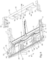
- power blocks 55 and 56 are connected to cross-member 3, and the position of power blocks 55 and 56 can be adjusted in a direction of arrow "B" ( Figs. 4 and 5A ) as required for a particular application.
- Phone or data lines 70 can be routed from data receptacles 32.
- Removable end covers 50 and 51 are utilized to cover data lines 70 adjacent data receptacles 32, and cover 52 may be utilized to cover data lines 70 extending along cross-member 3.
- End bracket structures 4 and 5 include openings 71, and power lines 61 and data lines 70 can be routed through opening 71.
- a conventional power plug connector 72 is provided at the end of power line 61
- a conventional connector 73 is provided at the end of data line 70.
- the power and/or data lines may also be routed through openings 69 in utility trough 35.
- other power and/or data connecting arrangements may also be utilized to connect the power and data lines to the power and phone lines in a building structure or the like.
- multi-cord power supply assemblies 74 may be connected to power block 55 and/or power block 56.
- multi-cord power supplies 74 include a base plate 75 that connects to side 76 of power block 55, 56, and a plurality of insulated power lines 77 extend from base plates 75.
- Plug receptacles 78 provide for connection to standard power plugs to thereby supply power to various electrical devices used in connection with worksurface assembly 1.
- Power blocks 55 and 56 include transverse flaps 81 (see also Fig. 5 ) that extend outwardly away from opposite sides 76. When assembled, flaps 81 extend behind sidewall 66 (see also Fig. 4 ) of cover 52 at edges 82 and 83 of cut out 67, and edges 84 and 85 of cut out 68. An end portion 88 of power blocks 55 and 56 is positioned below cover 52 when assembled, and includes tabs 89 having openings 90 that receive conventional threaded fasteners or the like to thereby secure power blocks 55 and 56 to cross-member 3. Tabs 89 thereby form brackets 62 and 63 ( Fig.
- End portion 88 may be constructed from a relatively thin metal material or other suitable material, and includes opposite sidewalls 91 and 92. Openings 93 and 94 through sidewalls 91 and 92, respectively, provide for routing of power lines 61 and data or phone lines 70 along cross member 3.
- cover 52 includes a horizontal top wall 65 and an upright sidewall 66. Cut outs 67 and 68 provide clearance for connecting power blocks 55 and 56 to cross-member 3.
- Cover 52 may be made of a relatively thin material, such that cutouts 67 and 68 may be manually formed during installation of power blocks 55 and 56 to thereby provide for positioning of the power blocks at the time worksurface assembly 1 is installed in an office environment or the like.
- a power block 55A includes an adjustable mounting arrangement 95 comprising a C-channel 96 mounted on end portion 88A of power block 55A.
- Threaded fasteners 98 extend through clearance openings 99 in cross member 3, and threadably engage threaded openings 86 in plate 97.
- the position of power block 58 can be adjusted in the direction of arrow "B" by sliding C-channel 96 along plate 97 with threaded fasteners 98 initially in a relatively loose state. Threaded fasteners 98 can then be tightened, and surfaces 113 of C-channel 96 bear against outer surface 114 of cross member 3 to thereby fix the position of power block 55A.
- end bracket structures 4 and 5 include a portion 103 having an upwardly opening slot 104 that aligns with a slot 110 in rail 20.
- Portion 103 of end bracket structures 4 and 5 also includes a base portion 105, and a side portion 106 that extend towards rear edge surface 100 of worksurface top 10 to form edge surfaces 107 and 108, respectively.
- portions of rear edge surface 100 of worksurface top 10 may abut or contact edge surfaces 107 and 108 such that the rear edge surface of the worksurface top is spaced-apart from rail 20 to form gap 101.
- mechanism 15 ( Fig. 1 ) also limits rearward travel of worksurface top 10. Accordingly, in use, rear edge surface 100 of worksurface top 10 may not always contact edge surfaces 107 and 108 ( Fig.
- top 10 When top 10 is in the open position ( Fig. 3 ), power lines can be connected to power receptacles 31 and/or plugs 78 ( Fig. 5 ), and phone/data lines can be connected to data receptacles 32, and routed along utility trough 35 as required. Top 10 is then closed, and power and/or data lines 61 and 70, respectively, can be routed through gap 101 ( Fig. 6 ).
- one or more accessories such as shelf 22, monitor support arm unit 23, and document support unit 24 may be secured to rail 20.
- Each of the accessories includes connecting structure 115 that secures accessory units 22, 23, and 24 to rail 20.
- upwardly extending structure 116 of accessories 22, 23, and 24 is rigidly connected to connecting structure 115.
- Connecting structure 115 includes an L-shaped portion 118 including a vertical leg 119 and a horizontal leg 120. In the illustrated example, legs 119 and 120 are relatively flat flange or tab-like members.
- Extrusion 40 includes inwardly-extending flange portions 121 and 122 ( Fig. 11A ) defining inner surfaces 123 and 124, respectively, that together define an opening 125 of slot 110.
- Flange portions 121 and 122 form inwardly-facing lower surfaces 126 and 127, respectively, and upper portions 128 and 129 of rear wall 41 and front wall 42, respectively, form inwardly-facing surfaces 130 and 131.
- Angled wall portions 132 and 133 extend inwardly from front wall 42 and rear wall 41, respectively, and define angled upper surfaces 134 and 135.
- a horizontal base wall portion 136 extends between angled wall portions 132 and 134, to define an upwardly-facing base surface 137 and vertical side surfaces 138 and 139.
- Connecting structure 115 includes an extension 140 that extends downwardly from horizontal leg 120 of connecting structure 115.
- Inwardly-facing surface 141 of vertical leg 119 is spaced-apart from vertical surface 142 formed by extension 140 to define a space 143.
- outer surface 144 of front wall 42 of extrusion 40 is closely received against inwardly facing surface 141 of vertical leg 119, and inner surface 123 of inwardly extending flange portion 121 of extrusion 40 is closely received against or adjacent vertical surface 142 of extension 140, and a downwardly-facing surface 146 of horizontal leg 120 of L-shaped portion 118 abuts an upwardly-facing surface 145 of inwardly-extending flange portion 121 of extrusion 40.
- An end portion 148 of extension 140 includes first and second opposite side surfaces 149 and 150, and an end surface 151.
- a notch 152 is formed by orthogonal surfaces 153 and 154 formed in end portion 148. When assembled ( Fig. 11 ), end surface 151 of end portion 148 of extension 140 abuts upwardly facing base surface 137 of extrusion 40, surface 154 of notch 152 abuts vertical side surface 139 of extrusion 40, and surface 153 of notch 152 is spaced apart from a small distance a surface 147 of extrusion 40.
- connecting structure 115 and extrusion 40 may be configured somewhat differently such that not all of these surfaces actually simultaneously abut or contact one another.
- surface 151 of extension 141 may, in use, be spaced apart from surface 137 of extrusion 40, and contact between lower surfaces 146 and 155 of horizontal leg 120 and upwardly-facing surfaces 145 and 156 of extrusion 40 may provide the primary vertical support for connecting structure 115 when mounted to rail 20.
- Contact between surface 141 of leg 119 and surface 144 of extrusion 40 and/or contact between surfaces 142 and 150 of extension 140 and surfaces 123 and 124 of extrusion 40 may provide the primary horizontal locating features.
- accessory units 22, 23, and 24 may include a mounting structure or device 315 instead of a connecting structure 115.
- monitor support arm unit 23 comprises a mounting structure 315, a bracket 317 having a horizontal arm or web 318, and a vertical arm or web 319 that is connected to an upwardly extending structure 316.
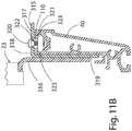
- a threaded fastener 320 extends through an opening 322 in horizontal arm 318, and threadably engages an anchor or nut 321 disposed in slot 110.
- nut 321 includes opposite side surfaces 323 that engage opposite surfaces 130 and 131 of slot 110 to prevent rotation of anchor 321 relative to extrusion 40 upon tightening of threaded fastener 320.
- mounting structure 315 When threaded fastener 320 is loose, it can be slid along slot 110 to change the position of mounting structure 315 and accessory unit 23. When threaded fastener 320 is tightened, anchor 321 bears against surfaces 126 and 127 of slot 110. In this way, mounting structure 315 provides a clamp to securely fasten monitor support arm unit 23 to rail 20.
- connecting structure 115 is shifted vertically relative to rail 20 in the direction of arrow "C" ( Fig. 11A ).
- connecting structure 115 When connecting structure 115 is fully engaged with slot 110 of rail 20 as shown in Fig. 11 , gravitational forces tend to maintain engagement between connecting structure 115 and rail 20, and the configuration of connecting structure 115 and extrusion 40 provide a secure, moment-resisting connection that retains accessories 22, 23, and/or 24 in an upright position.
- the position of accessories 22, 23, and 24 may be adjusted by sliding the accessory along rail 20. If required, the accessory may be raised slightly to disengage connecting structure 115 from rail 20 to permit such adjustment.
- a clamp-type mounting structure 315 Fig. 11B
- threaded fastener 320 may be tightened and/or loosened as required to permit adjustment of the position of monitor support arms 23 on extrusion 40 of rail 20.
- the accessory units include a shelf 22 ( Fig. 1 ) having a horizontal surface 160 and a raised portion 161 extending along a rear edge 162 of horizontal surface 160.
- a pair of structural uprights 163 extend from horizontal surface 160 and connecting structures 115 are disposed at the lower ends of extensions 163.
- the length of extensions 163 may vary as required to provide a desired height for horizontal surface 160.
- the size of horizontal surface 160 may be selected to meet the needs of a particular application.
- a plurality of shelves 22 having different sizes and/or heights may be fabricated, and a shelf having a specific size and/or height may be selected as required for a particular application.
- an angled document holder or support 24 includes a pair of extensions 163 with connecting structure 115 to provide for mounting of documents 424 to rail 20 at a selected position.
- Dual monitor arm support 23 includes a base portion 165 having a mounting structure 115 that provides for mounting of monitor support arm unit 23 to rail 20.
- mounting structure 115 of monitor support arm unit 23 is somewhat wider than connecting structures 115 of shelf 22 and document support 24 to provide for stable mounting of monitor support arm unit 23 utilizing a single connecting structure 115.
- Connecting structure 115 of monitor support arm unit 23 has substantially the same cross sectional configuration as shown in Figs. 11 and 11A .
- dual monitor support arm unit 23 includes a first arm 167, and a second arm 168 extending from a single base portion 165 to support first and second monitors or display screens 169 and 170.
- Arms 167 and 168 are configured to articulate according to a known design to provide for adjustment of the positions of screens 169 and 170.
- a pair of slide assemblies 172 (see also Fig. 1 ) slidably connect worksurface top 10 to frame 2.
- End bracket structure 5 includes a downwardly-extending portion 173, and a plurality of rollers 174 are rotatably mounted to the downwardly-extending portion.
- a C-shaped channel 175 is rigidly mounted to lower side surface 176 of top 10, and rollers 174 engage the C-shaped channel to provide for back and forth movement of the top in the direction of arrow "A" ( Fig. 1 ) relative to frame 2.
- Rollers 174 and C-shaped channel 175 may be of a known design, such that the details of these components will not be further described herein.
- a latching or locking mechanism 15 provides for controlled movement of top 10 relative to frame 2.
- Mechanism 15 includes first and second pulleys 180 and 181, respectively that are pivotably connected to a bracket 182 at pins or pivots 183 and 184, respectively.
- Bracket 182 is secured to frame 2, such that first and second pulleys 180 and 181 remain stationary relative to frame 2.
- a first cable 185 has a first end 187 connected to a tension spring 188, and a second end 189 that is connected to a lever 190 at pin or pivot point 194.
- First cable 185 wraps around first pulley 180.
- a second cable 186 includes a first end 191 connected to tension spring 188, and a second end 192 connected to lever 190 at pin or connecting point 194 via a tension fitting 193.
- Tension fitting 193 includes a compression spring 195 that is relatively stiff, and ensures that cables 185 and 186 remain in tension despite dimensional variations in the length of the cables, spacing of pulleys 180 and 181, or the like.
- Lever 190 is pivotably mounted to bracket 182 (and thereby to frame 2) at pin or pivot 196.
- Top 10 is connected to mechanism 15 at first end 191 of second cable 186, such that the top moves with the first end.
- Mechanism 15 is in the configuration shown in Fig. 8 when top 10 is in the closed position. If a user pulls on top 10 without moving lever 190, a tension force on cable 186 is generated due to the force transmitted into cable 186 at end 191. Because compression spring 195 is relatively stiff, top 10 cannot move an appreciatable distance. Also, because the centerline of second cable 186 extends along a line that is "inside" of pin or pivot point 196 of lever 190, tension force on second cable 186 will tend to drive lever 190 in a clockwise direction about pin or pivot point 196, such that mechanism 15 remains in the locked position shown in Fig. 8 .
- a user applies a force to outer end 197 of lever 190 to thereby rotate the lever in a counterclockwise direction about pivotable pin 196.
- pin 194 connecting cables 185 and 186 to lever 190 moves downwardly, such that the centerline of cable 186 is "below" pin or pivot point 196 as shown in Fig. 9 .
- end 191 of cable 186 begins to move away from second pulley 181, and top 10 also therefore begins to move.
- spring 188 stretches, thereby storing energy.
- lever 190 If, however, a user continues to push lever 190, thereby rotating the lever in a counterclockwise position, the lever will reach a "center” position wherein pin or pivot 194 of lever 190 is vertically aligned with pin or pivot 196 along line “V" Fig. 10 .
- mechanism 15 When mechanism 15 is at the "center” position, the mechanism will tend to remain in this position even if the external force applied to lever 190 is removed.
- spring 188 if lever 190 is rotated slightly past the "center” position, spring 188 will contract, thereby pulling the lever to the open position shown in Fig. 10 .
- end 191 of cable 186 moves toward first pulley 180, and top 10 also moves outwardly to the open position due to contraction of the spring.
- Spring 188 is configured to provide sufficient tension to move top 10 outwardly without application of additional force by a user once mechanism 15 has moved just beyond the center position.
- the center position has been described as being the position wherein lever 190 extend vertically along line "V" ( Fig. 10 )
- the actual center point occurs when the moments generated by cables 185 and 186 on lever 190 about pin or pivot point 196 are equal.
- the center position may occur when lever 190 is not vertical.
- top 10 When top 10 is in the open position and mechanism 15 is in the configuration shown in Fig. 10 , a force tending to the close the top can be applied to the top by a user. This force acts on end 191 of cable 186, thereby tending to stretch spring 188. If the external force applied to top 10 by a user is large enough, the tension force on cable 185 will rotate lever 190 in a clockwise direction until it passes through the center position. Once lever 190 passes the center position, spring 188 will generate sufficient force to pull top 10 closed, and return mechanism 15 to the configuration shown in Fig. 8 . If, however, a user releases the forces applied to top 10 before mechanism 15 reaches the center postion, tension generated by spring 188 will return the mechanism from the center position to the configuration shown in Fig. 10 , thereby closing the top. In addition to mechanism 15, stops may be utilized to restrict movement of top 10 relative to frame 2 in both the open and closed positions.
- Mechanism 200 may also be utilized to control movement of top 10 relative to frame 2.
- Mechanism 200 includes a bracket 201 including a base portion 202 that is configured to rigidly connect the mechanism with cross member 3, and an outwardly-extending cantilevered portion 203.
- a pair of rollers 204 are rotatably mounted to bracket 201, and engage lower surface 176 of top 110 to moveably support the top.
- Mechanism 200 includes a base member 206 that is secured to a plate 207 by threaded fasteners 208.
- a main link 212 includes an end 213 having a pair of spaced-apart extensions 214 forming a gap 115 therebetween.
- extension 210 of base member 206 is positioned in gap 215 between extensions 214 of main link 212, and a pin 216 extends through openings 217 in extensions 214, and through opening 218 in base member 206 to thereby pivotably interconnect end 213 of main link 212 to the base member.
- Main link 212 also includes an end member 223 that is connected to a body portion 225 of main link 212 by a rod 224.
- a compression spring is disposed within the body portion 225, such that end member 223 can move axially somewhat relative to body portion 225.
- a first link 228 includes a first opening 232 at a first end 236, and a second opening 233 at a second end 237.
- a second link 230 includes a first opening 234 at a first end 238, and a second opening 235 at a second end 239.
- pin 222 extends through openings 232 and 234 in links 228 and 230, respectively, and through opening 221 of end member 223 of main link 212 to thereby pivotably interconnect first ends 234 and 236 of links 230 and 228, respectively, to second end 220 of the main link.
- a pin 240 is received in opening 233 at second end 237 of link 228, and pin 240 is also received in opening 242 in side wall 244 of cantilever portion 203 of bracket 201 to thereby pivotably interconnect end 237 of link 228 to bracket 201.
- a pin 241 is received in opening 235 of link 203 and opening 243 in side wall 245 of bracket 201 to thereby pivotally interconnect second end 239 of link 230 to the bracket.
- a pin 250 is mounted to base member 206 with opposite ends protruding therefrom, and a pin 253 is received in an opening 254 through body member 225 of main link 212.
- End 255 of spring 251 connects to pin 250, and end 256 of spring 251 connects to pin 253.
- end 257 of spring 252 connects to pin 250, and end 258 of spring 252 connects to pin 253.
- springs 251 and 252 are in tension, and therefore rotatably bias main link 212 about pin 216 such that main link 212 tends to rotate towards top 10.
- a release link 260 is positioned between links 228 and 230.
- Release link 260 includes openings 261 and 262 that receive pins 240 and 241, respectively, to thereby pivotably mount release link 260 to bracket 201.
- pin 263 is received in openings 264 and 265 of release link 260.
- end 266 of pin 263 contacts edge surface 268 of link 228, and end 267 of pin 263 contacts edge surface 269 of link 230 upon rotation of release link 260 to thereby rotate links 228 and 230 and release mechanism 200.
- Release link 260 includes opposite side portions 271 and 272, and a central portion 270 that extends between opposite side portions 271 and 272.
- a cable is connected to central portion 270 to selectively rotate release link 260 about pins 240 and 241 to release mechanism 200.
- body member 225 of main link 212 includes an internal cavity 276, and a compression spring 275 is disposed within the internal cavity.
- rod 224 comprises a threaded rod that extends through an opening 277 in a first end 278 of body member 225, and a threaded nut 279 adjustably limits the travel of threaded rod 224 relative to body member 225 upon contact with first end 278 of body member 225.
- a threaded nut 281 and washer are disposed on an end 280 of threaded rod 224, and engage a first end 282 of compression spring 275.
- a second end 283 of compression spring 275 bears against an inner side surface to a 4 of body member 225 directly adjacent opening 277, such that compression spring 275 biases threaded rod 224 inwardly toward body portion 225.
- threaded nut 279 prevents travel of threaded rod 224 past a selected position.
- mechanism 200 If mechanism 200 is in the fully closed or locked position of Fig. 17 , and a user applies a force "F" to top 10, main link 212 will be put into compression, and the length of main link 212 will not change significantly due to threaded nut 279 acting on end 278 of body member 225. However, if a user pulls on top 10 in a direction opposite of arrow "F" ( Fig. 17 ), main link 212 will be placed in tension. If enough force is applied, compression spring 275 will be compressed somewhat, and threaded rod 224 will move relative to main body portion 225, thereby causing main link 212 to lengthen somewhat. However, compression spring 275 is quite stiff, such that top 10 cannot be moved appreciably unless mechanism 200 is released.
- a cable assembly 290 operably interconnects release lever 288 and release link 260, and a first end 291 of a cable 293 is connected release lever 288, and a second 292 of cable 293 is connected to central portion 270 of release link 260.
- a user rotates a release lever 288 in a direction of arrow "R" about pivot point 289.
- lever 288 is shown as being pivotable about a horizontal axis formed by pin 289, lever 288 may be mounted in such a way that it pivots about a vertical axis. Rotation of release lever 288 in the direction of arrow "R” thereby tensions cable 293, causing release link 260 to rotate in a clockwise direction about pins 240 and 241.
- mechanism 200 moves past the position shown in Fig. 18 towards the partially open configuration shown in Fig. 19 , mechanism 200 is no longer locked. If an external force is then applied to top 10, mechanism 200 will move from the partially open configuration of Fig. 19 to the fully open configuration of Figs. 20 and 21 . As mechanism 200 moves from the partially open configuration of Fig. 19 to the fully open configuration of Figs. 20 and 21 , links 228 and 230 rotate in a clockwise direction about pins 240 and 241. At a mid point, the center lines of links 228 and 230 are positioned to define a center point represented by line "V1" ( Fig. 20 ).
- tension springs 251 and 252 generate a moment biasing main link 212 in a counter clockwise direction about pin 216.
- mechanism 200 When mechanism 200 is at the center position (i.e., links 228 and 230 are aligned with line "V1", the mechanism is in a "dead” or center position, and springs 251 and 252 do not cause the mechanism to move to either the closed position or the open position. If, however, top 10 is moved to a partially open position as shown in Fig. 19 (i.e., a position between the closed position and the center position), and the external force applied to top 10 by a user is removed, springs 251 and 252 will cause top 10 to move back to the fully closed position.
- top 10 To move top 10 from the fully open position (e.g. Figs. 20 and 21 ) to the closed position (e.g. Figs. 16 and 17 ), a user applies an external force “F” ( Fig. 16 ) to top 10. Force “F” will cause mechanism 200 to begin to close. If mechanism 200 is moved beyond the center position represented by line “V1" ( Fig. 20 ), top 10 will move to the fully closed position due to the force generated by springs 251 and 252, even if external force "F” is removed immediately after mechanism 200 moves past the center position. If external “F” is, however, removed prior to mechanism 200 reaching the center position, the mechanism will cause top 10 to move outwardly back to the fully extended position as shown in Figs. 20 and 21 .
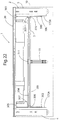
- worksurface assembly 1 may include a mechanism 300 that ensures top 10 translates linearly with respect to frame structure 2 without "racking" or binding.
- Mechanism 300 includes a first cable 301 having a first end 302 secured to a first C-channel 175A, and a second end 303 that is secured to a second C-channel 175B.
- a second cable 304 includes a first end 305 that is secured to first C-channel 175A, and a second end 306 that is secured to a second C-channel 175B.
- C- channels 175A and 175B are fixed to top 10, and move with the top.
- Pulleys 307 and 308 are rotatably mounted to cross member 3 adjacent end bracket structure 4, and pulleys 309 and 310 are rotatably mounted to cross member 3 adjacent end bracket structure 5.
- First cable 301 is supported by pulleys 308 and 310, and second cable 304 is supported by pulleys 307 and 309.
- First cable 301 and second cable 304 cross at center point 311. In use, ends 302, 303, 305 and 306 of cables 301 and 304 move with top 10, and tension on cables 301 and 304 ensures that the top translates linearly with respect to frame structure 2 without "racking" or binding.
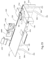
- a worksurface assembly 500 includes a support structure 502 that my comprise a plurality of legs 506 that are attached to brackets 504 and 505.
- Support structure 502 may also include a cross-member 503, and a rail 520, each of which have opposite ends connected to bracket structures 504 and 505.
- a plurality of accessory units such as an angle document support unit 24A, a monitor support arm 23A, and a shelf 22A may be secured to rail 520 utilizing a connecting arrangement that is substantially the same as described in more detail above in connection with Figs. 11 , 11A and 11B .
- one or more privacy screens 533 may be mounted to rail 520 in upwardly and/or downwardly extending configurations.
- a keyboard support platform 17A and a computer 13A may be mounted to support structure 502.
- a support structure or arm 16A includes horizontally-extending hooks 519 that are received in horizontal slots 558 in front side 587 of cross member 503.
- a screw (not shown) or other suitable fastener is utilized to secure arm to cross member 503.
- Arm 16A supports keyboard support platform 17.
- a computer support structure 12A may be utilized to support a computer CPV 13A.
- Support structure 12A includes horizontally-extending hooks 519 that are received in slots 558 in front side 587 of cross member 503. Screws (not shown) or other suitable fasteners may be utilized to secure support structure 12A to cross member 503.
- there are several groups of slots 558 such that arm 16A and support 12A can be installed in selected ones of slots 558 at a user-selected horizontal position.
- worksurface assembly 500 is configured to be supported in a free standing manner on a floor surface by legs 506.
- bracket structures 504 and 505 may also be configured to mount worksurface assembly 500 to a partition system or the like (not shown).
- support structure 502 does not necessarily need to include legs 506, but rather could comprise a variety of structures configured to support worksurface assembly 500 in a variety of configurations.
- Worksurface member 510 is configured to move between an extended or open position "B" ( Fig. 24 ) and a retracted or closed position "A" ( Fig. 25 ).
- a pair of slide assemblies 172A movably support worksurface member 510 on support structure 502.
- Slide assemblies 172A may have substantially the same construction as slide assemblies 172 described in more detail above in connection with the worksurface assembly of Fig. 13 .
- Worksurface assembly 500 may include an anti-racking mechanism that is substantially similar to the mechanism described in more detail above in connection with Fig. 22 .
- worksurface assembly 500 may include a tray structure 511 that provides for routing of power and data lines 521 and 522, respectively, and for mounting of power and data blocks 512 and 513, respectively.
- motion control or latching device or mechanism 515 includes a first bracket 530 that is secured to cross member 503.
- Mechanism 515 includes a plurality of rollers 531 that engage a lower surface 516 ( Fig. 23 ) of worksurface member 510 to movably support a central portion of worksurface member 510.
- worksurface member 510 is also slidably supported by slide assemblies 172A.
- cross member 503 comprises a two inch by two inch square cross-sectional shape.
- First bracket 530 is also formed of metal, and it is welded to cross member 503.
- An optional cover 532 may be utilized to cover first bracket 530 to improve the appearance of motion control device 515.
- cover 532 is made of a polymer material.
- a second bracket 535 includes a first component 537 having a plurality of apertures 536 ( Fig. 27 ) that receive threaded fasteners (not shown) to secure second bracket 535 to lower surface 516 of worksurface member 510, such that second bracket 535 moves with worksurface member 510.
- Second bracket 535 includes a first component 537 that may be made of a polymer material, and a second component 538 that may be constructed of metal.
- Second component 538 has a shape that is generally plate-like, with a cut out portion 539.
- Second bracket 535 also includes a third component 541 that is rigidly interconnected with second component 538 by a plurality of pins 540A-540C (see also Fig. 28 ).
- Third component 541 is also substantially plate-like, and may be made of metal or other suitable material.
- First component 537 of second bracket 535 includes cylindrical portions 544 that are sandwiched between second component 538 and third component 541 to act as spacers, and pins 540A -540C extend through openings in cylindrical portions 544 of first component 537.
- second component 538 and third component 541 are shown as being two separate pieces, they may also comprise a single part made from polymer, metal, or other suitable material.
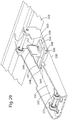
- a first engagement member such as a cam or cleat 542 is pivotably mounted to pin 540A, and a roller 543 is rotatably mounted on pin 540C.
- a second engagement or blade member 545 is mounted to first bracket 530, and includes a blade or protrusion 546 that is disposed between cam 542 and roller 543 when worksurface member 510 is in the retracted/closed position shown in Fig. 28 .
- cam 542 and roller 543 move with worksurface member 510, whereas blade member 545 remains stationary relative to cross member 503.
- blade member 545 includes a base 547 having a pair of bosses or protrusions 548 that extend through slots 549 in a bottom sidewall 550 of first bracket 530.
- a bolt 551 ( Fig. 30 ) is threadably received in a threaded opening 552 ( Fig. 29 ) of blade member 545, and a head 554 of bolt 551 as received in a recessed area 553 in sidewall 550 of first bracket 530.
- Blade member 545 includes a pair of pads 555 ( Fig. 30 ) having teeth 556 that frictionally engage upper surface 557 of first bracket 530 upon tightening of bolt 551.
- the pins and slots 548 and 549, respectively, bolt 551, and pads 555 together provide for side-to-side adjustment of the position of blade member 545 relative to first bracket 530.
- a tension spring 560 is connected to an end 561 of arm 562 of cam member 542, and spring 560 is also connected to a boss 563 or other connector located on second bracket 535.
- Spring 560 generates a force tending to rotate cam member 542 in a counter clockwise direction, thereby biasing cam surface 564 of cam member 542 into contact with first side surface 565 of blade 546.
- Cam surface 564 contacts first side surface 565 of blade 546 at a contact point 566 that is offset a distance "X" from axis of rotation 567 of cam member 542.
- cam surface 564 causes cam member 542 to wedge tightly against first side surface 565 of blade 546, thereby preventing movement of second bracket assembly 535 in the direction of the arrow "F". This, in turn, prevents movement of the worksurface member 510 from the retracted or closed position.
- cam member 542 becomes tightly wedged against first side surface 565 of blade 546, a substantial force that is normal to first side surface 565 is generated.
- roller 543 contacts second side surface 569 of blade 546 to thereby react forces generated by cam member 542 on blade 546. Because pins 540A and 540C are supported by second component 538 ( Fig. 27 ) and third component 541, pins 54A and 540C are very rigidly mounted to prevent outward movement of pins 540A and 540C.
- a release member 575 is movably mounted to lower surface 516 of worksurface member 510. Movable release member 575 is operably connected to the motion control mechanism or device 515 by a cable 576.
- cable 576 may comprise a Bowden cable having an outer sheath 577 and an inner cable 578.
- Inner cable 578 is connected to an end fitting 579 of arm 580 ( Fig. 31 ) of cam member 542, such that tension on inner cable 578 generates a release force "R" acting on cam member 542. Release force R tends to rotate cam member 542 in a clockwise direction ( Fig. 31 ), thereby moving cam surface 564 out of engagement with first side surface 565 of blade 546.
- bracket 504 includes a corner portion 507
- bracket 505 includes a corner portion 508.
- Corner portions 507 and 508 include grooves 523 and 524, respectively, that align with elongated groove or channel 525 in rail 520.
- Resilient pads or bumpers 526 and 527 are mounted to corners 507 and 508 of brackets 504 and 505, respectively (see also Fig. 32 ).
- motion control mechanism 515 generates a one-way retaining force that permits worksurface member 510 to be moved from the open position to the closed position, but prevents movement of worksurface member 510 from the closed position to the open position, unless motion control mechanism 515 is released utilizing release member 575.
- the one-way retaining action of motion control mechanism 515 retains the worksurface member 510 against the resilient members 526 and 527.
- Motion control device 515 and resilient members 526 and 527 thereby tightly retain worksurface member 510 in the closed position in a manner that prevents movement of worksurface member 510 relative to support structure 502.
- motion control mechanism 515 prevents movement of worksurface member 510 towards the open position regardless of the precise position of worksurface member 510 relative to support structure 502 (provided blade 546 is in an engagement with cam surface 564), motion control mechanism 515 and resilient members 526 and 527 together provide for tight closure of worksurface member 510 regardless of dimensional variations or other tolerances that may be present in the various components of the worksurface assembly 500.
- the side-to-side position of blade member 545 relative to support structure 2 can be adjusted by loosening bolt 551 ( Fig. 30 ), shifting the position of blade member 545, followed by tightening of bolt 551.
- bolt 551 may be loosened with worksurface member 510 in the closed position.
- Worksurface member 510 can then be moved manually side-to-side as required until opposite side edges 517 and 518 ( Fig. 25 ) of worksurface member 510 are aligned with outer surfaces 528 and 529 of brackets 504 and 505, respectively.
- Bolt 551 can then be tightened to lock blade member 545 to first bracket 530. This ensures that worksurface member 510 will have a proper side-to-side position relative to support structure 2 when in the closed position.
- This adjustment permits the position of worksurface member 510 to be precisely adjusted relative to support structure 2 when worksurface member 510 is in the closed position, regardless of tolerances that may be present in the various components of worksurface assembly 500. This prevents an unsightly visual affect that would occur if worksurface member 510 were not properly aligned with brackets 504 and 505 of support structure 502.
- first component 537 of second bracket assembly 535 includes a slot 570 that is aligned with cut out 539 of second component 538.
- Tapered surfaces 571 and 572 of first component 537 act as guide surfaces to align blade 546 with slot 570 as blade 546 enters slot 570 as worksurface member 510 is moved from the open position to the closed position.
- End 568 of blade 546 includes tapered surfaces 573 and 574.
- blade 546 is somewhat misaligned relative to slot 570, as worksurface member 510 is shifted to the closed position the surfaces 573 and 574 of blade 546 contact surfaces 571 and 572, respectively, of first component 537, thereby shifting component 537 and worksurface member 510 in a direction that is transverse relative to the rearward motion of worksurface member 510. This shifts worksurface member 510 sideways (if required) as it is closed to provide proper side-to-side alignment of worksurface member 510 relative to support structure 502 when in the closed position.
- worksurface assembly 500 includes a tray structure 511 extending between brackets 504 and 505.
- Power blocks 512 and data blocks 513 may be mounted on or within tray structure 511 to provide connection points for power lines 61A ( Fig. 23 ) and/or data lines 70A for various items of equipment such as a printer/scanner 581.
- displays 169A and 170A, computer 13A, and other powered devices utilized in conjunction with worksurface assembly 500 may be connected to the power blocks 512 and/or data blocks 513.
- tray structure 511 includes a tray member 582 having a front portion 583 with an upwardly-extending flange 586 extending upwardly along a front side 587 of cross member 503. Threaded fasteners or other suitable connectors (not shown) may be utilized to secure flange 586 of tray member 582 to cross member 503. Tray member 582 also includes a rear portion 584 having upwardly and rearwardly-extending flanges 588 and 589, respectively. Rearwardly extending flange 589 is received in a groove or slot 590 in rail or extrusion 520 to thereby support rear portion 584 of tray member 582.
- Tray member 582 further includes a vertical step 591, and a divider or septum 585 that extends upwardly from tray member 582 at step 591.
- Divider 585 includes a transversely-extending flange 592 that is secured to front portion 583 of tray member 582 by spot welding, mechanical fasteners (not shown), or other suitable arrangement.
- Tray member 582 and divider 585 together define a front passageway or space 593, and a rear passageway or space 594. Front and rear passageways 593 extend transversely below worksurface member 510. When worksurface member 510 is in the open position shown in Fig. 26 , rear edge 509 of worksurface member 510 is spaced apart from rail 520, thereby providing access to rear passageway or space 594.
- rear edge 509 of worksurface member 510 is positioned above or adjacent divider 585, such that access to front passageway or space 593 is substantially blocked.
- rear edge 509 of worksurface member 510 is spaced-apart from rail 520 to form an elongated gap or slot 514 (see also Fig. 23 ) through which power and data lines 61A and 70A, respectively, can be routed.
- data block 513 includes a plurality of data receptacles 595 that are configured to receive conventional data line connectors (not shown).
- Data supply lines 522 can be routed through a cut out 596 in divider 584, and through an elliptical opening 598 in bracket 505.
- Data lines 70A that are connected to the data receptacles 595 can be routed through rear passageway 594 as required, and then through gap or slot 514 ( Fig. 26 ) to various electrical devices or the like that may be positioned on worksurface member 510 as required.
- power blocks 512 include slots 599 on opposite side faces 600 of block 512. Slots 599 receive edges 601 formed by cutout 602 in divider 585 (see also Fig. 33 ). Tabs or flanges 609 extend from power blocks 512, and threaded fasteners 603 or other suitable connectors extend through openings 610 in tabs 609 and through openings 611 in tray member 582 to secure the power block 512 to tray member 582.
- Power blocks 512 include a plurality of power receptacles 604 on the opposite side faces 600 of power block 512, and power supply lines for various power accessories such as display screens 169A and 170A ( Fig.
- a modular power system (not shown) may be mounted to tray member 582.
- the modular power system may be substantially similar to modular power systems of the type utilized in office partition systems and the like.
- modular power components may be utilized in place of power blocks 512.
- worksurface assembly 500 may be "hard wired" utilizing electrical components (not shown) of the type utilized in "permanent" building walls.
- rail 520 includes an upwardly-opening slot 110A that is substantially similar to the slot 110 described in more detail above in connection with Fig. 11A .
- Rail 520 also includes a downwardly-opening slot 110B may have substantially the same shape and configuration as slot 110 described in more detail above in connection with Fig. 11A .
- a downwardly-extending privacy screen 533 may be mounted to slot 110B, and an upwardly-extending screen 533A may be mounted to slot 110A of rail 520.
- Bases 534 and 534A of screens 533 and 533A, respectively, may include connectors 608 and 608A, respectively, that are substantially similar to the connecting arrangement described in more detail above in connection with Fig. 11B .
- connectors 608 and 608A may comprise spring-loaded snap fit connectors (not shown).
- Screens 533 and 533A may include a plurality of spaced-apart connectors 608 and 608A, respectively, to secure the screens 533 and 533A to the rail 520.
Landscapes
- Tables And Desks Characterized By Structural Shape (AREA)
- Installation Of Indoor Wiring (AREA)
- Casings For Electric Apparatus (AREA)
- Specific Conveyance Elements (AREA)
- Feeding Of Articles To Conveyors (AREA)
Description
- Various types of desks and other worksurfaces have been developed for use in offices and other such environments. Various types of powered equipment may be utilized in connection with a worksurface in a modern office environment. Also, phones, modems, and other such devices may require the use of data lines. Efforts have been made to develop worksurfaces providing for power and data routing. Efforts have also been made to accommodate handling and organization of documents and other items.
-
WO 2006/128218 discloses a desk for computer equipment comprising a fixed portion and a moveable portion slidable from a closed to an opened position, wherein the moveable portion may be locked preventing movement in either direction. -
EP 0 145 410 A2 discloses a worksurface assembly comprising a support structure, a power supply system and a worksurface member; wherein the worksurface member is movably connected to the support structure for movement between extended and retracted positions relative to the support structure. - According to the present invention a work surface assembly comprises:
- a support structure;
- a power supply system including at least one power supply receptacle; a worksurface member movably connected to the support structure for movement between extended and retracted positions relative to the support structure, and wherein the worksurface member substantially prevents access to the power supply receptacle when in the retracted position, and permits access to the power supply receptacle when the worksurface member is in the extended position, and wherein the worksurface member moves in a first direction from the extended position to the retracted position, and moves in a second direction from the retracted position to the extended position, the worksurface member, defining an enlarged upwardly-facing upper surface;
- a movement control device when engaged, permitting movement of the worksurface member in the first direction, and preventing movement of the worksurface member in the second direction to retain the worksurface member in any retracted position; and when disengaged, permitting movement in the first and second direction.
-
-
Fig. 1 is an isometric view of a worksurface assembly according to one aspect of the present invention; -
Fig. 2 is a fragmentary, top plan view of a portion of the worksurface assembly ofFig. 1 ; -
Fig. 3 is a fragmentary isometric of a portion of the worksurface assembly ofFig. 1 with the worksurface top member in an open position; -
Fig. 4 is a fragmentary isometric of a portion of the worksurface assembly ofFig. 1 ; -
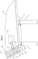
Fig. 5 is an isometric view of a component that may be utilized in the worksurface assembly ofFig. 1 to provide electric power; -
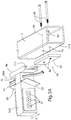
Fig. 5A is an isometric view of another component according to another aspect of the present invention that may be utilized in the worksurface assembly ofFig. 1 to provide electric power; -
Fig. 6 is a fragmentary isometric view of a portion of the worksurface ofFig. 1 with the worksurface top member in a closed position; -
Fig. 7 is a cross-sectional view taken along the line VII-VII;Fig. 6 showing a locking or latching mechanism for the movable worksurface top member and a power trough and rail; -
Fig. 8 is a partially schematic view of the latching or lock mechanism ofFig. 7 when the worksurface top member is in a closed position; -
Fig. 9 is a partially schematic view of the latching or lock mechanism ofFig. 7 when the worksurface top member is in an intermediate position; -
Fig. 10 is a partially schematic view of the latching or lock mechanism ofFig. 7 when the worksurface top member is in a fully open position; -
Fig. 11 is a fragmentary cross-sectional view of the support rail and an accessory unit taken along the line XI-XI;Fig. 2 ; -
Fig. 11A is a fragmentary, exploded view of a portion of the rail and connecting structure of an accessory unit; -
Fig. 11B is a fragmentary cross-sectional view of the support rail and an accessory unit mounting arrangement according to another aspect of the present invention; -
Fig. 12 is a fragmentary, isometric view of a portion of the worksurface assembly ofFig. 1 ; -
Fig. 13 is a fragmentary view of a portion of the worksurface assembly taken along the line XIII-XIII;Fig. 12 -
Fig. 14 is an isometric view of a latching or lock mechanism according to another aspect of the present invention; -
Fig. 15 is an exploded isometric view of the mechanism ofFig. 14 ; -
Fig. 16 is a side view of the mechanism ofFig. 14 with the worksurface top member in a closed position; -
Fig. 17 is a side view of the mechanism ofFig. 14 with the worksurface top member in a closed position; -
Fig. 18 is a cross-sectional view showing the mechanism ofFig. 14 as it is being released from the closed position ofFigs. 16 and 17 ; -
Fig. 19 is a cross-sectional view of the mechanism ofFig. 14 as the worksurface top member is opening; -
Fig. 20 is a view of the mechanism ofFig. 14 with the worksurface top member in an open position; -
Fig. 21 is a view of the mechanism with the worksurface top member in an open position; -
Fig. 22 is a plan view of the worksurface assembly showing an anti-racking mechanism; -
Fig. 23 is an isometric view of a worksurface assembly according to another aspect of the present invention; -
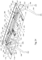
Fig. 24 is an isometric view of the worksurface assembly ofFig. 23 showing the worksurface member in an open position; -
Fig. 25 is an isometric view of the worksurface assembly ofFig. 23 showing the worksurface member in a closed position; -
Fig. 26 is a cross-sectional view of the worksurface assembly ofFig. 25 taken along the line XXVI-XXVI; -
Fig. 27 is a partially fragmentary isometric view of the motion control device of the worksurface assembly ofFig. 23 ; -
Fig. 28 is a partially fragmentary isometric view of the motion control device ofFig. 27 ; -
Fig. 29 is a partially fragmentary isometric view of the motion control device ofFig. 27 wherein some of the components have been removed to show the remaining components; -
Fig. 30 is a partially fragmentary isometric view of a portion of the device ofFig. 29 ; -
Fig. 31 is a plan view of a portion of the motion control device ofFig. 27 ; -
Fig. 32 is a partially fragmentary isometric view of a portion of the worksurface assembly ofFig. 23 ; and -
Fig. 33 is a partially fragmentary plan view showing the power block ofFig. 31 . - For purposes of description herein, the terms "upper," "lower," "right," "left, " "rear, " "front, " "vertical, " "horizontal, and derivatives thereof shall relate to the invention as oriented in
Fig. 1 . However, it is to be understood that the invention may assume various alternative orientations and step sequences, except where expressly specified to the contrary. It is also to be understood that the specific devices and processes illustrated in the attached drawings and described in the following specification are simply exemplary embodiments of the inventive concepts defined in the appended claims. Hence, specific dimensions and other physical characteristics relating to the embodiments disclosed herein are not to be considered as limiting, unless the claims expressly state otherwise. - With reference to
Fig. 1 , aworksurface assembly 1 not claimed in the present invention includes aframe structure 2 and a worksurfacetop member 10 that is movably mounted to the frame structure for back and forth movement in the direction indicated by arrow "A". As discussed in more detail below, a latch orlocking mechanism 15 provides for controlled movement ofworksurface top 10 relative toframe structure 2.Rear legs 6 and 7 andfront legs frame structure 2 and provide support forworksurface assembly 1.Adjustable glides 11 mounted to lower ends of legs 6-9 may be utilized to account for irregularities in a support surface such as a floor. As also described in more detail below, arail 20 extends along arear portion 21 ofworksurface assembly 1, and provides for mounting of various accessory units such as ashelf 22, a dual monitorsupport arm unit 23, and an angleddocument support unit 24. Worksurfaceassembly 1 also includes a power anddata supply system 30 including autility trough 35 and a plurality ofpower receptacles 31 anddata receptacles 32 that can be accessed when worksurfacetop member 10 is moved to the open position. -
Frame 2 includesend bracket structures tubular cross member 3 andrail 20.Tubular cross member 3 andrail 20 extend betweenend bracket structures end bracket structures Fig. 7 ,extrusion 40 may include screw-receivingportions extrusion 40 withend bracket structures Fig. 12 ,end bracket structures boss 27 that is received inopen end 28 ofcross member 3. Threaded fasteners or the like (not shown) may be utilized to interconnectbracket structures member 3 andrail 20.Bracket structures Cross member 3 may comprise a tubular steel or aluminium member or other suitable structure/material. Legs 6-9 are rigidly connected to endbracket structures optional computer support 12 may be secured to thecross member 3 to support acomputer 13 in a hanging manner belowtop 10. Akeyboard support structure 16 may also be secured to crossmember 3 to provide for mounting of akeyboard support platform 17. In the illustrated example,keyboard support structure 16 is configured to mount any one of a number of commerciallyavailable support platforms 17 utilizing a known mounting interface. In this way,keyboard structure 16 provides for mounting of a selectedkeyboard support platform 17 as required for a particular application. A plurality ofopenings 18 incross member 13 are positioned at equally-spaced intervals alongupper surface 19 ofcross-member 3. During assembly,openings 25 inkeyboard support structure 16 andopenings 26 incomputer support 12 are aligned with selected ones ofopenings 18, and convention threaded fasteners or the like (not shown) are received inopenings keyboard support 16 tocross-member 3.Openings 18 thereby provide for mounting ofkeyboard support structure 16 andcomputer support 12 at a selected side-to-side position alongcross member 3 as required for a particular application. - With further reference to
Figs. 2-4 ,utility trough 35 is generally U-shaped, and opens upwardly to provide for access topower receptacles 31 anddata receptacles 32 whenworksurface top 10 is in the open position. With further reference toFig. 7 ,utility trough 35 is formed, in part, by atrough member 36 that is connected to crossmember 3 andrail 20. In the illustrated example,rail 20 comprises anextrusion member 40 made of aluminum or the like.Extrusion 40 includes arear wall 41 and afront wall 42. First and second flanges orlips 43 and 44 project forwardly fromfront wall 42, and form agroove 45 therebetween that receives a rearwardly-projectingflange 46 ofutility trough member 36 to thereby support theutility trough member 36. Abracket 48 connects afront portion 47 ofutility trough member 36 to cross-member 3 to thereby supportfront portion 47 ofutility trough member 36. In the illustrated example,utility trough member 36 is made of a sheet metal. Other suitable materials may, however, be utilized. - Referring again to
Figs. 2-4 ,worksurface assembly 1 includes an electrical power supply system includingpower blocks cross-member 3, and extend intoutility trough 35. A plurality ofpower receptacles 31 are mounted on opposite side faces 57 and 58 ofpower block 55, and opposite faces 59 and 60 ofpower block 56.Power lines 61 can be routedadjacent cross-member 3 to provide power topower blocks central cover 52cover power lines 61 when installed. As discussed in more detail below in connection withFigs. 5 and5A , power blocks 55 and 56 (or 55A) are connected tocross-member 3, and the position ofpower blocks Figs. 4 and5A ) as required for a particular application. - Phone or
data lines 70 can be routed fromdata receptacles 32. Removable end covers 50 and 51 are utilized to coverdata lines 70adjacent data receptacles 32, and cover 52 may be utilized to coverdata lines 70 extending alongcross-member 3.End bracket structures openings 71, andpower lines 61 anddata lines 70 can be routed throughopening 71. In the illustrated example, a conventionalpower plug connector 72 is provided at the end ofpower line 61, and aconventional connector 73 is provided at the end ofdata line 70. The power and/or data lines may also be routed throughopenings 69 inutility trough 35. However, other power and/or data connecting arrangements may also be utilized to connect the power and data lines to the power and phone lines in a building structure or the like. - With further reference to
Fig. 5 , multi-cordpower supply assemblies 74 may be connected topower block 55 and/orpower block 56. In the illustrated example, multi-cord power supplies 74 include abase plate 75 that connects toside 76 ofpower block insulated power lines 77 extend frombase plates 75.Plug receptacles 78 provide for connection to standard power plugs to thereby supply power to various electrical devices used in connection withworksurface assembly 1. - Power blocks 55 and 56 include transverse flaps 81 (see also
Fig. 5 ) that extend outwardly away fromopposite sides 76. When assembled, flaps 81 extend behind sidewall 66 (see alsoFig. 4 ) ofcover 52 atedges end portion 88 ofpower blocks cover 52 when assembled, and includestabs 89 havingopenings 90 that receive conventional threaded fasteners or the like to therebysecure power blocks cross-member 3.Tabs 89 thereby form brackets 62 and 63 (Fig. 4 ) to permit mounting ofpower blocks utility trough 35 as indicated by arrow "B" (Figs. 3 and4 ).End portion 88 may be constructed from a relatively thin metal material or other suitable material, and includesopposite sidewalls Openings sidewalls power lines 61 and data orphone lines 70 alongcross member 3. Referring again toFigs. 3 and4 , cover 52 includes a horizontaltop wall 65 and anupright sidewall 66. Cutouts power blocks cross-member 3.Cover 52 may be made of a relatively thin material, such thatcutouts power blocks time worksurface assembly 1 is installed in an office environment or the like. - With further reference to
Fig. 5A , apower block 55A according to another aspect of the present invention includes anadjustable mounting arrangement 95 comprising a C-channel 96 mounted onend portion 88A ofpower block 55A. Threadedfasteners 98 extend throughclearance openings 99 incross member 3, and threadably engage threadedopenings 86 inplate 97. The position ofpower block 58 can be adjusted in the direction of arrow "B" by sliding C-channel 96 alongplate 97 with threadedfasteners 98 initially in a relatively loose state. Threadedfasteners 98 can then be tightened, and surfaces 113 of C-channel 96 bear againstouter surface 114 ofcross member 3 to thereby fix the position ofpower block 55A. - With reference to
Fig. 6 , whenworksurface top 10 is in the closed position,rear edge surface 100 of top 10 is spaced-apart fromrail 20 to form agap 101 betweenrail 20 andrear edge surface 100. Power and/ordata lines utility trough 35 throughgap 101 to thereby supply power forvarious devices 102 positioned onworksurface top 10, or to devices positioned adjacent the worksurface top. With further reference toFigs. 2 and12 ,end bracket structures portion 103 having anupwardly opening slot 104 that aligns with aslot 110 inrail 20.Portion 103 ofend bracket structures base portion 105, and aside portion 106 that extend towardsrear edge surface 100 ofworksurface top 10 to form edge surfaces 107 and 108, respectively. Whenworksurface top 10 is in the closed position, portions ofrear edge surface 100 ofworksurface top 10 may abut or contact edge surfaces 107 and 108 such that the rear edge surface of the worksurface top is spaced-apart fromrail 20 to formgap 101. As discussed in more detail below, mechanism 15 (Fig. 1 ) also limits rearward travel ofworksurface top 10. Accordingly, in use,rear edge surface 100 ofworksurface top 10 may not always contact edge surfaces 107 and 108 (Fig. 12 ) ofend bracket structures edge surfaces Fig. 3 ), power lines can be connected topower receptacles 31 and/or plugs 78 (Fig. 5 ), and phone/data lines can be connected todata receptacles 32, and routed alongutility trough 35 as required.Top 10 is then closed, and power and/ordata lines Fig. 6 ). - Referring again to
Fig. 1 , one or more accessories such asshelf 22, monitorsupport arm unit 23, and documentsupport unit 24 may be secured to rail 20. Each of the accessories includes connectingstructure 115 that securesaccessory units Figs. 11 and11A , upwardly extendingstructure 116 ofaccessories structure 115.Connecting structure 115 includes an L-shapedportion 118 including avertical leg 119 and ahorizontal leg 120. In the illustrated example,legs -
Extrusion 40 includes inwardly-extendingflange portions 121 and 122 (Fig. 11A ) defininginner surfaces opening 125 ofslot 110.Flange portions lower surfaces upper portions rear wall 41 andfront wall 42, respectively, form inwardly-facingsurfaces Angled wall portions front wall 42 andrear wall 41, respectively, and define angledupper surfaces base wall portion 136 extends betweenangled wall portions base surface 137 and vertical side surfaces 138 and 139. -
Connecting structure 115 includes anextension 140 that extends downwardly fromhorizontal leg 120 of connectingstructure 115. Inwardly-facingsurface 141 ofvertical leg 119 is spaced-apart fromvertical surface 142 formed byextension 140 to define aspace 143. When assembled (Fig. 11 )outer surface 144 offront wall 42 ofextrusion 40 is closely received against inwardly facingsurface 141 ofvertical leg 119, andinner surface 123 of inwardly extendingflange portion 121 ofextrusion 40 is closely received against or adjacentvertical surface 142 ofextension 140, and a downwardly-facingsurface 146 ofhorizontal leg 120 of L-shapedportion 118 abuts an upwardly-facingsurface 145 of inwardly-extendingflange portion 121 ofextrusion 40. - An
end portion 148 ofextension 140 includes first and second opposite side surfaces 149 and 150, and anend surface 151. Anotch 152 is formed byorthogonal surfaces end portion 148. When assembled (Fig. 11 ),end surface 151 ofend portion 148 ofextension 140 abuts upwardly facingbase surface 137 ofextrusion 40,surface 154 ofnotch 152 abutsvertical side surface 139 ofextrusion 40, andsurface 153 ofnotch 152 is spaced apart from a small distance asurface 147 ofextrusion 40. Also,lower surface 155 ofhorizontal leg 120 of L-shapedportion 118 of connectingstructure 115 abuts upper 156 of inwardly-extendingflange portion 122 ofextrusion 40, andsurface 142 ofextension 140 abutssurface 123 ofextrusion 40.Surface 150 ofextension 140 is positioned closely adjacent, or in contact with,surface 124 ofextrusion 40. It will be understood that connectingstructure 115 andextrusion 40 may be configured somewhat differently such that not all of these surfaces actually simultaneously abut or contact one another. For example,surface 151 ofextension 141 may, in use, be spaced apart fromsurface 137 ofextrusion 40, and contact betweenlower surfaces horizontal leg 120 and upwardly-facingsurfaces extrusion 40 may provide the primary vertical support for connectingstructure 115 when mounted torail 20. Contact betweensurface 141 ofleg 119 andsurface 144 ofextrusion 40 and/or contact betweensurfaces extension 140 andsurfaces extrusion 40 may provide the primary horizontal locating features. - With further reference to
Fig. 11B ,accessory units device 315 instead of a connectingstructure 115. In the illustrated example, monitorsupport arm unit 23 comprises a mountingstructure 315, abracket 317 having a horizontal arm orweb 318, and a vertical arm orweb 319 that is connected to an upwardly extendingstructure 316. A threadedfastener 320 extends through anopening 322 inhorizontal arm 318, and threadably engages an anchor ornut 321 disposed inslot 110. In the illustrated example,nut 321 includes opposite side surfaces 323 that engageopposite surfaces slot 110 to prevent rotation ofanchor 321 relative toextrusion 40 upon tightening of threadedfastener 320. When threadedfastener 320 is loose, it can be slid alongslot 110 to change the position of mountingstructure 315 andaccessory unit 23. When threadedfastener 320 is tightened,anchor 321 bears againstsurfaces slot 110. In this way, mountingstructure 315 provides a clamp to securely fasten monitorsupport arm unit 23 to rail 20. - To install or remove an
accessory rail 20, connectingstructure 115 is shifted vertically relative to rail 20 in the direction of arrow "C" (Fig. 11A ). When connectingstructure 115 is fully engaged withslot 110 ofrail 20 as shown inFig. 11 , gravitational forces tend to maintain engagement between connectingstructure 115 andrail 20, and the configuration of connectingstructure 115 andextrusion 40 provide a secure, moment-resisting connection that retainsaccessories accessories rail 20. If required, the accessory may be raised slightly to disengage connectingstructure 115 fromrail 20 to permit such adjustment. If a clamp-type mounting structure 315 (Fig. 11B ) is included in the accessory unit, threadedfastener 320 may be tightened and/or loosened as required to permit adjustment of the position ofmonitor support arms 23 onextrusion 40 ofrail 20. - In the illustrated example, the accessory units include a shelf 22 (
Fig. 1 ) having ahorizontal surface 160 and a raisedportion 161 extending along arear edge 162 ofhorizontal surface 160. A pair ofstructural uprights 163 extend fromhorizontal surface 160 and connectingstructures 115 are disposed at the lower ends ofextensions 163. The length ofextensions 163 may vary as required to provide a desired height forhorizontal surface 160. Similarly, the size ofhorizontal surface 160 may be selected to meet the needs of a particular application. A plurality ofshelves 22 having different sizes and/or heights may be fabricated, and a shelf having a specific size and/or height may be selected as required for a particular application. Similarly, an angled document holder orsupport 24 includes a pair ofextensions 163 with connectingstructure 115 to provide for mounting of documents 424 to rail 20 at a selected position. Dualmonitor arm support 23 includes abase portion 165 having a mountingstructure 115 that provides for mounting of monitorsupport arm unit 23 to rail 20. In the illustrated example, mountingstructure 115 of monitorsupport arm unit 23 is somewhat wider than connectingstructures 115 ofshelf 22 anddocument support 24 to provide for stable mounting of monitorsupport arm unit 23 utilizing a single connectingstructure 115.Connecting structure 115 of monitorsupport arm unit 23 has substantially the same cross sectional configuration as shown inFigs. 11 and11A . In the illustrated example, dual monitorsupport arm unit 23 includes afirst arm 167, and asecond arm 168 extending from asingle base portion 165 to support first and second monitors ordisplay screens Arms screens - With further reference to
Figs. 12 and13 , a pair of slide assemblies 172 (see alsoFig. 1 ) slidably connectworksurface top 10 toframe 2.End bracket structure 5 includes a downwardly-extendingportion 173, and a plurality ofrollers 174 are rotatably mounted to the downwardly-extending portion. A C-shapedchannel 175 is rigidly mounted tolower side surface 176 of top 10, androllers 174 engage the C-shaped channel to provide for back and forth movement of the top in the direction of arrow "A" (Fig. 1 ) relative to frame 2.Rollers 174 and C-shapedchannel 175 may be of a known design, such that the details of these components will not be further described herein. - Referring back to
Fig. 7-10 , a latching or lockingmechanism 15 provides for controlled movement of top 10 relative to frame 2.Mechanism 15 includes first andsecond pulleys bracket 182 at pins or pivots 183 and 184, respectively.Bracket 182 is secured toframe 2, such that first andsecond pulleys first cable 185 has afirst end 187 connected to atension spring 188, and asecond end 189 that is connected to alever 190 at pin orpivot point 194.First cable 185 wraps aroundfirst pulley 180. Asecond cable 186 includes afirst end 191 connected totension spring 188, and asecond end 192 connected to lever 190 at pin or connectingpoint 194 via a tension fitting 193. Tension fitting 193 includes acompression spring 195 that is relatively stiff, and ensures thatcables pulleys Lever 190 is pivotably mounted to bracket 182 (and thereby to frame 2) at pin orpivot 196.Top 10 is connected tomechanism 15 atfirst end 191 ofsecond cable 186, such that the top moves with the first end. -
Mechanism 15 is in the configuration shown inFig. 8 when top 10 is in the closed position. If a user pulls on top 10 without movinglever 190, a tension force oncable 186 is generated due to the force transmitted intocable 186 atend 191. Becausecompression spring 195 is relatively stiff, top 10 cannot move an appreciatable distance. Also, because the centerline ofsecond cable 186 extends along a line that is "inside" of pin orpivot point 196 oflever 190, tension force onsecond cable 186 will tend to drivelever 190 in a clockwise direction about pin orpivot point 196, such thatmechanism 15 remains in the locked position shown inFig. 8 . - To release
mechanism 15, a user applies a force toouter end 197 oflever 190 to thereby rotate the lever in a counterclockwise direction aboutpivotable pin 196. Aslever 190 rotates, pin 194 connectingcables cable 186 is "below" pin orpivot point 196 as shown inFig. 9 . As shown inFig. 9 , end 191 ofcable 186 begins to move away fromsecond pulley 181, and top 10 also therefore begins to move. Aslever 190 rotates from the position fromFig. 8 to the position shown inFig. 2 due to a force applied by a user,spring 188 stretches, thereby storing energy. If a user releases the force applied to lever 190 when it is in the position ofFig. 9 ,spring 188 will contract, thereby returning themechanism 15 to the configuration shown inFig. 8 . Althoughcables mechanism 15 is in configuration ofFig. 9 , the moment generated about pin orpivot point 196 bycable 185 is greater, thereby causemechanism 15 to change from the configuration ofFig. 9 to the configuration ofFig. 8 if the force applied to lever 190 is removed. - If, however, a user continues to push
lever 190, thereby rotating the lever in a counterclockwise position, the lever will reach a "center" position wherein pin or pivot 194 oflever 190 is vertically aligned with pin or pivot 196 along line "V"Fig. 10 . Whenmechanism 15 is at the "center" position, the mechanism will tend to remain in this position even if the external force applied to lever 190 is removed. However, iflever 190 is rotated slightly past the "center" position,spring 188 will contract, thereby pulling the lever to the open position shown inFig. 10 . Asspring 188 contracts, end 191 ofcable 186 moves towardfirst pulley 180, and top 10 also moves outwardly to the open position due to contraction of the spring.Spring 188 is configured to provide sufficient tension to move top 10 outwardly without application of additional force by a user oncemechanism 15 has moved just beyond the center position. Although the center position has been described as being the position whereinlever 190 extend vertically along line "V" (Fig. 10 ), the actual center point occurs when the moments generated bycables lever 190 about pin orpivot point 196 are equal. Depending upon the relative locations of pin or pivotPoints lever 190 is not vertical. - When top 10 is in the open position and
mechanism 15 is in the configuration shown inFig. 10 , a force tending to the close the top can be applied to the top by a user. This force acts onend 191 ofcable 186, thereby tending to stretchspring 188. If the external force applied to top 10 by a user is large enough, the tension force oncable 185 will rotatelever 190 in a clockwise direction until it passes through the center position. Oncelever 190 passes the center position,spring 188 will generate sufficient force to pull top 10 closed, and returnmechanism 15 to the configuration shown inFig. 8 . If, however, a user releases the forces applied to top 10 beforemechanism 15 reaches the center postion, tension generated byspring 188 will return the mechanism from the center position to the configuration shown inFig. 10 , thereby closing the top. In addition tomechanism 15, stops may be utilized to restrict movement of top 10 relative to frame 2 in both the open and closed positions. - With further reference to
Figs. 14 and15 , amechanism 200 according to another aspect not claimed in the present invention may also be utilized to control movement of top 10 relative to frame 2.Mechanism 200 includes abracket 201 including abase portion 202 that is configured to rigidly connect the mechanism withcross member 3, and an outwardly-extendingcantilevered portion 203. A pair ofrollers 204 are rotatably mounted tobracket 201, and engagelower surface 176 of top 110 to moveably support the top.Mechanism 200 includes abase member 206 that is secured to aplate 207 by threadedfasteners 208. Threaded fasteners or the like (not shown) are received inopenings 209 ofplate 207 to thereby rigidlysecure base member 206 andplate 207 tolower side surface 176 of top 10. Amain link 212 includes anend 213 having a pair of spaced-apart extensions 214 forming agap 115 therebetween. When assembled,extension 210 ofbase member 206 is positioned in gap 215 betweenextensions 214 ofmain link 212, and apin 216 extends throughopenings 217 inextensions 214, and throughopening 218 inbase member 206 to therebypivotably interconnect end 213 ofmain link 212 to the base member. Main link 212 also includes anend member 223 that is connected to a body portion 225 ofmain link 212 by arod 224. As described in more detail below, a compression spring is disposed within the body portion 225, such thatend member 223 can move axially somewhat relative to body portion 225. Afirst link 228 includes afirst opening 232 at afirst end 236, and asecond opening 233 at asecond end 237. Similarly, asecond link 230 includes afirst opening 234 at afirst end 238, and asecond opening 235 at asecond end 239. When assembled,pin 222 extends throughopenings links opening 221 ofend member 223 ofmain link 212 to thereby pivotably interconnect first ends 234 and 236 oflinks second end 220 of the main link. - A
pin 240 is received in opening 233 atsecond end 237 oflink 228, and pin 240 is also received in opening 242 inside wall 244 ofcantilever portion 203 ofbracket 201 to therebypivotably interconnect end 237 oflink 228 tobracket 201. Similarly, apin 241 is received in opening 235 oflink 203 andopening 243 inside wall 245 ofbracket 201 to thereby pivotally interconnectsecond end 239 oflink 230 to the bracket. - A
pin 250 is mounted tobase member 206 with opposite ends protruding therefrom, and apin 253 is received in anopening 254 through body member 225 ofmain link 212. End 255 ofspring 251 connects to pin 250, and end 256 ofspring 251 connects to pin 253. Similarly, end 257 ofspring 252 connects to pin 250, and end 258 ofspring 252 connects to pin 253. As described in more detail below, springs 251 and 252 are in tension, and therefore rotatably biasmain link 212 aboutpin 216 such thatmain link 212 tends to rotate towardstop 10. - A
release link 260 is positioned betweenlinks Release link 260 includesopenings pins mount release link 260 tobracket 201. When assembled,pin 263 is received inopenings release link 260. As described in more detail below, in use, end 266 ofpin 263contacts edge surface 268 oflink 228, and end 267 ofpin 263contacts edge surface 269 oflink 230 upon rotation ofrelease link 260 to thereby rotatelinks release mechanism 200.Release link 260 includesopposite side portions central portion 270 that extends betweenopposite side portions central portion 270 to selectively rotaterelease link 260 aboutpins mechanism 200. - With further reference to
Fig. 17 , body member 225 ofmain link 212 includes aninternal cavity 276, and acompression spring 275 is disposed within the internal cavity. In the illustrated example,rod 224 comprises a threaded rod that extends through an opening 277 in afirst end 278 of body member 225, and a threadednut 279 adjustably limits the travel of threadedrod 224 relative to body member 225 upon contact withfirst end 278 of body member 225. A threaded nut 281 and washer are disposed on anend 280 of threadedrod 224, and engage afirst end 282 ofcompression spring 275. Asecond end 283 ofcompression spring 275 bears against an inner side surface to a 4 of body member 225 directly adjacent opening 277, such thatcompression spring 275 biases threadedrod 224 inwardly toward body portion 225. However, threadednut 279 prevents travel of threadedrod 224 past a selected position. - If
mechanism 200 is in the fully closed or locked position ofFig. 17 , and a user applies a force "F" to top 10,main link 212 will be put into compression, and the length ofmain link 212 will not change significantly due to threadednut 279 acting onend 278 of body member 225. However, if a user pulls on top 10 in a direction opposite of arrow "F" (Fig. 17 ),main link 212 will be placed in tension. If enough force is applied,compression spring 275 will be compressed somewhat, and threadedrod 224 will move relative to main body portion 225, thereby causingmain link 212 to lengthen somewhat. However,compression spring 275 is quite stiff, such that top 10 cannot be moved appreciably unlessmechanism 200 is released. - When top 10 is in the fully closed position of
Figs. 16 and 17 , the pivotable interconnection point (pins 240, 241) oflinks bracket 201 is below a line extending through the pivotable interconnection (pin 216) ofmain link 212 tobase member 206 and the pivotable connection (pin 222 of main link 212) tolinks Figs. 16 and 17 ),main link 212 is placed in tension. The force generated onpin 222 andlinks links pins mechanism 200 from moving to an open position as shown inFigs. 20 and 21 . - A
cable assembly 290 operably interconnects releaselever 288 andrelease link 260, and afirst end 291 of acable 293 is connectedrelease lever 288, and a second 292 ofcable 293 is connected tocentral portion 270 ofrelease link 260. To releasemechanism 200, a user rotates arelease lever 288 in a direction of arrow "R" aboutpivot point 289. Althoughlever 288 is shown as being pivotable about a horizontal axis formed bypin 289,lever 288 may be mounted in such a way that it pivots about a vertical axis. Rotation ofrelease lever 288 in the direction of arrow "R" therebytensions cable 293, causingrelease link 260 to rotate in a clockwise direction aboutpins release link 260 rotates, ends 266 and 267 ofpin 263 contact edge surfaces 268 and 269 oflinks links Figs. 16 and 17 ) aboutpins links pins Fig. 18 ). Further rotation oflinks causes mechanism 200 to move to a partially open configuration as shown inFig. 19 . - Once
mechanism 200 moves past the position shown inFig. 18 towards the partially open configuration shown inFig. 19 ,mechanism 200 is no longer locked. If an external force is then applied to top 10,mechanism 200 will move from the partially open configuration ofFig. 19 to the fully open configuration ofFigs. 20 and 21 . Asmechanism 200 moves from the partially open configuration ofFig. 19 to the fully open configuration ofFigs. 20 and 21 ,links pins links Fig. 20 ). As discussed above, tension springs 251 and 252 generate a moment biasingmain link 212 in a counter clockwise direction aboutpin 216. Whenmechanism 200 is at the center position (i.e.,links Fig. 19 (i.e., a position between the closed position and the center position), and the external force applied to top 10 by a user is removed, springs 251 and 252 will cause top 10 to move back to the fully closed position. Conversely, if top 10 is moved to a position past the center position (i.e. between the center position and the fully open position), springs 251 and 252 will cause the mechanism to move to the fully open position shown inFigs. 20 and 21 even if the external force applied by the user is released oncemechanism 200 is moved just beyond the center position represented by line "V1". - To move top 10 from the fully open position (e.g.
Figs. 20 and 21 ) to the closed position (e.g.Figs. 16 and 17 ), a user applies an external force "F" (Fig. 16 ) totop 10. Force "F" will causemechanism 200 to begin to close. Ifmechanism 200 is moved beyond the center position represented by line "V1" (Fig. 20 ), top 10 will move to the fully closed position due to the force generated bysprings mechanism 200 moves past the center position. If external "F" is, however, removed prior tomechanism 200 reaching the center position, the mechanism will cause top 10 to move outwardly back to the fully extended position as shown inFigs. 20 and 21 . - With further reference to
Fig. 22 ,worksurface assembly 1 may include amechanism 300 that ensures top 10 translates linearly with respect to framestructure 2 without "racking" or binding.Mechanism 300 includes afirst cable 301 having afirst end 302 secured to a first C-channel 175A, and asecond end 303 that is secured to a second C-channel 175B. Asecond cable 304 includes afirst end 305 that is secured to first C-channel 175A, and asecond end 306 that is secured to a second C-channel 175B. C-channels Pulleys member 3 adjacentend bracket structure 4, and pulleys 309 and 310 are rotatably mounted to crossmember 3 adjacentend bracket structure 5.First cable 301 is supported bypulleys second cable 304 is supported bypulleys First cable 301 andsecond cable 304 cross atcenter point 311. In use, ends 302, 303, 305 and 306 ofcables cables structure 2 without "racking" or binding. - With further reference to
Figs. 23-25 , aworksurface assembly 500 according to the present invention includes asupport structure 502 that my comprise a plurality oflegs 506 that are attached tobrackets Support structure 502 may also include a cross-member 503, and arail 520, each of which have opposite ends connected tobracket structures - Referring again to
Fig. 23 , a plurality of accessory units such as an angledocument support unit 24A, amonitor support arm 23A, and ashelf 22A may be secured to rail 520 utilizing a connecting arrangement that is substantially the same as described in more detail above in connection withFigs. 11 ,11A and11B . As discussed in more detail below, one ormore privacy screens 533 may be mounted torail 520 in upwardly and/or downwardly extending configurations. Also, akeyboard support platform 17A and acomputer 13A may be mounted to supportstructure 502. A support structure orarm 16A includes horizontally-extendinghooks 519 that are received inhorizontal slots 558 infront side 587 ofcross member 503. A screw (not shown) or other suitable fastener is utilized to secure arm to crossmember 503.Arm 16A supportskeyboard support platform 17. Acomputer support structure 12A may be utilized to support acomputer CPV 13A.Support structure 12A includes horizontally-extendinghooks 519 that are received inslots 558 infront side 587 ofcross member 503. Screws (not shown) or other suitable fasteners may be utilized to securesupport structure 12A to crossmember 503. In the illustrated example, there are several groups ofslots 558, such thatarm 16A andsupport 12A can be installed in selected ones ofslots 558 at a user-selected horizontal position. In the illustrated example,worksurface assembly 500 is configured to be supported in a free standing manner on a floor surface bylegs 506. However,bracket structures worksurface assembly 500 to a partition system or the like (not shown). Thus,support structure 502 does not necessarily need to includelegs 506, but rather could comprise a variety of structures configured to supportworksurface assembly 500 in a variety of configurations. -
Worksurface member 510 is configured to move between an extended or open position "B" (Fig. 24 ) and a retracted or closed position "A" (Fig. 25 ). A pair ofslide assemblies 172A movablysupport worksurface member 510 onsupport structure 502.Slide assemblies 172A may have substantially the same construction asslide assemblies 172 described in more detail above in connection with the worksurface assembly ofFig. 13 .Worksurface assembly 500 may include an anti-racking mechanism that is substantially similar to the mechanism described in more detail above in connection withFig. 22 . As described in more detail below,worksurface assembly 500 may include atray structure 511 that provides for routing of power anddata lines - With further reference to
Fig. 27 , motion control or latching device ormechanism 515 includes afirst bracket 530 that is secured to crossmember 503.Mechanism 515 includes a plurality ofrollers 531 that engage a lower surface 516 (Fig. 23 ) ofworksurface member 510 to movably support a central portion ofworksurface member 510. As discussed above,worksurface member 510 is also slidably supported byslide assemblies 172A. In the illustrated example,cross member 503 comprises a two inch by two inch square cross-sectional shape.First bracket 530 is also formed of metal, and it is welded to crossmember 503. Anoptional cover 532 may be utilized to coverfirst bracket 530 to improve the appearance ofmotion control device 515. In the illustrated example, cover 532 is made of a polymer material. - A
second bracket 535 includes afirst component 537 having a plurality of apertures 536 (Fig. 27 ) that receive threaded fasteners (not shown) to securesecond bracket 535 tolower surface 516 ofworksurface member 510, such thatsecond bracket 535 moves withworksurface member 510.Second bracket 535 includes afirst component 537 that may be made of a polymer material, and asecond component 538 that may be constructed of metal.Second component 538 has a shape that is generally plate-like, with a cut outportion 539.Second bracket 535 also includes athird component 541 that is rigidly interconnected withsecond component 538 by a plurality ofpins 540A-540C (see alsoFig. 28 ).Third component 541 is also substantially plate-like, and may be made of metal or other suitable material.First component 537 ofsecond bracket 535 includescylindrical portions 544 that are sandwiched betweensecond component 538 andthird component 541 to act as spacers, and pins 540A -540C extend through openings incylindrical portions 544 offirst component 537. Althoughsecond component 538 andthird component 541 are shown as being two separate pieces, they may also comprise a single part made from polymer, metal, or other suitable material. - A first engagement member such as a cam or
cleat 542 is pivotably mounted to pin 540A, and aroller 543 is rotatably mounted onpin 540C. A second engagement orblade member 545 is mounted tofirst bracket 530, and includes a blade orprotrusion 546 that is disposed betweencam 542 androller 543 whenworksurface member 510 is in the retracted/closed position shown inFig. 28 . As discussed in more detail below,cam 542 androller 543 move withworksurface member 510, whereasblade member 545 remains stationary relative to crossmember 503. - With further reference to
Figs. 29 and30 ,blade member 545 includes a base 547 having a pair of bosses orprotrusions 548 that extend throughslots 549 in abottom sidewall 550 offirst bracket 530. A bolt 551 (Fig. 30 ) is threadably received in a threaded opening 552 (Fig. 29 ) ofblade member 545, and ahead 554 ofbolt 551 as received in a recessedarea 553 insidewall 550 offirst bracket 530.Blade member 545 includes a pair of pads 555 (Fig. 30 ) havingteeth 556 that frictionally engageupper surface 557 offirst bracket 530 upon tightening ofbolt 551. The pins andslots bolt 551, andpads 555 together provide for side-to-side adjustment of the position ofblade member 545 relative tofirst bracket 530. - In use, when
worksurface member 510 is moved to the retracted or closed position (Fig. 31 ),blade 546 is positioned betweencam 542 androller 543. Atension spring 560 is connected to anend 561 ofarm 562 ofcam member 542, andspring 560 is also connected to aboss 563 or other connector located onsecond bracket 535.Spring 560 generates a force tending to rotatecam member 542 in a counter clockwise direction, thereby biasingcam surface 564 ofcam member 542 into contact withfirst side surface 565 ofblade 546.Cam surface 564 contactsfirst side surface 565 ofblade 546 at acontact point 566 that is offset a distance "X" from axis ofrotation 567 ofcam member 542. Asworksurface member 510 is moved from the extended (open) position to the retracted (closed) position, end 568 ofblade 546contacts cam surface 564, thereby causingcam member 542 to rotate in a clockwise direction, with theside surface 565 ofblade 546 slidably contactingcam surface 564. This contact generates a moment in the clockwise direction that overcomes the counterclockwise force generated byspring 560. However, if a user pulls outwardly on aworksurface member 510 whenworksurface member 510 is in the retracted (closed) position (Fig. 31 ), friction between cam surface 564 (Fig. 31 ) andfirst side surface 565 ofblade 546 generates a force tending to rotatecam member 542 in a counter clockwise direction. The shape ofcam surface 564 causescam member 542 to wedge tightly againstfirst side surface 565 ofblade 546, thereby preventing movement ofsecond bracket assembly 535 in the direction of the arrow "F". This, in turn, prevents movement of theworksurface member 510 from the retracted or closed position. Ascam member 542 becomes tightly wedged againstfirst side surface 565 ofblade 546, a substantial force that is normal tofirst side surface 565 is generated. However,roller 543 contactssecond side surface 569 ofblade 546 to thereby react forces generated bycam member 542 onblade 546. Becausepins Fig. 27 ) andthird component 541, pins 54A and 540C are very rigidly mounted to prevent outward movement ofpins - With reference back to
Fig. 24 , arelease member 575 is movably mounted tolower surface 516 ofworksurface member 510.Movable release member 575 is operably connected to the motion control mechanism ordevice 515 by acable 576. With reference toFig. 27 ,cable 576 may comprise a Bowden cable having anouter sheath 577 and aninner cable 578.Inner cable 578 is connected to an end fitting 579 of arm 580 (Fig. 31 ) ofcam member 542, such that tension oninner cable 578 generates a release force "R" acting oncam member 542. Release force R tends to rotatecam member 542 in a clockwise direction (Fig. 31 ), thereby movingcam surface 564 out of engagement withfirst side surface 565 ofblade 546. This releasescam member 542, such thatblade 546 can be moved in a direction opposite arrow "F" (Fig. 31 ), thereby allowingworksurface member 510 to be moved from the retracted (closed) position to the open position. Thus, in use, a user pulls on release member 575 (Fig. 24 ) to thereby releasecam member 542 ofmotion control device 515, and then pulls outwardly onworksurface member 510 in the direction of arrow "A" (Fig. 24 ), thereby movingworksurface member 510 from the retracted (closed) position to the extended (open) position. - With reference to
Fig. 24 ,bracket 504 includes a corner portion 507, andbracket 505 includes acorner portion 508.Corner portions 507 and 508 includegrooves 523 and 524, respectively, that align with elongated groove orchannel 525 inrail 520. Resilient pads orbumpers corners 507 and 508 ofbrackets Fig. 32 ). Whenworksurface member 510 is shifted to the retracted (closed) position,rear edge 509 ofworksurface member 510 contactsresilient pads motion control mechanism 515 generates a one-way retaining force that permitsworksurface member 510 to be moved from the open position to the closed position, but prevents movement ofworksurface member 510 from the closed position to the open position, unlessmotion control mechanism 515 is released utilizingrelease member 575. The one-way retaining action ofmotion control mechanism 515 retains theworksurface member 510 against theresilient members Motion control device 515 andresilient members worksurface member 510 in the closed position in a manner that prevents movement ofworksurface member 510 relative to supportstructure 502. Becausemotion control mechanism 515 prevents movement ofworksurface member 510 towards the open position regardless of the precise position ofworksurface member 510 relative to support structure 502 (providedblade 546 is in an engagement with cam surface 564),motion control mechanism 515 andresilient members worksurface member 510 regardless of dimensional variations or other tolerances that may be present in the various components of theworksurface assembly 500. - Also, the side-to-side position of
blade member 545 relative to supportstructure 2 can be adjusted by loosening bolt 551 (Fig. 30 ), shifting the position ofblade member 545, followed by tightening ofbolt 551. In use, bolt 551 may be loosened withworksurface member 510 in the closed position.Worksurface member 510 can then be moved manually side-to-side as required until opposite side edges 517 and 518 (Fig. 25 ) ofworksurface member 510 are aligned withouter surfaces 528 and 529 ofbrackets Bolt 551 can then be tightened to lockblade member 545 tofirst bracket 530. This ensures thatworksurface member 510 will have a proper side-to-side position relative to supportstructure 2 when in the closed position. This adjustment permits the position ofworksurface member 510 to be precisely adjusted relative to supportstructure 2 whenworksurface member 510 is in the closed position, regardless of tolerances that may be present in the various components ofworksurface assembly 500. This prevents an unsightly visual affect that would occur ifworksurface member 510 were not properly aligned withbrackets support structure 502. - With reference to
Figs. 27 and31 ,first component 537 ofsecond bracket assembly 535 includes aslot 570 that is aligned with cut out 539 ofsecond component 538.Tapered surfaces first component 537 act as guide surfaces to alignblade 546 withslot 570 asblade 546 entersslot 570 asworksurface member 510 is moved from the open position to the closed position.End 568 ofblade 546 includes taperedsurfaces blade 546 is somewhat misaligned relative to slot 570, asworksurface member 510 is shifted to the closed position thesurfaces blade 546contact surfaces first component 537, thereby shiftingcomponent 537 andworksurface member 510 in a direction that is transverse relative to the rearward motion ofworksurface member 510. This shiftsworksurface member 510 sideways (if required) as it is closed to provide proper side-to-side alignment ofworksurface member 510 relative to supportstructure 502 when in the closed position. It will be appreciated that the side-to-side adjustability ofblade member 545 relative to supportstructure 2, in combination withslot 570 and guidesurfaces first component 537 ofsecond bracket 535, permits proper positioning ofworksurface member 510 relative to supportstructure 502 regardless of tolerances in the various components. - With reference back to
Figs. 24 and25 ,worksurface assembly 500 includes atray structure 511 extending betweenbrackets Power blocks 512 and data blocks 513 may be mounted on or withintray structure 511 to provide connection points forpower lines 61A (Fig. 23 ) and/ordata lines 70A for various items of equipment such as a printer/scanner 581. In general, displays 169A and 170A,computer 13A, and other powered devices utilized in conjunction withworksurface assembly 500 may be connected to thepower blocks 512 and/or data blocks 513. - With further reference to
Figs. 26 and32 ,tray structure 511 includes atray member 582 having afront portion 583 with an upwardly-extendingflange 586 extending upwardly along afront side 587 ofcross member 503. Threaded fasteners or other suitable connectors (not shown) may be utilized to secureflange 586 oftray member 582 to crossmember 503.Tray member 582 also includes arear portion 584 having upwardly and rearwardly-extendingflanges flange 589 is received in a groove orslot 590 in rail orextrusion 520 to thereby supportrear portion 584 oftray member 582.Tray member 582 further includes avertical step 591, and a divider orseptum 585 that extends upwardly fromtray member 582 atstep 591.Divider 585 includes a transversely-extendingflange 592 that is secured tofront portion 583 oftray member 582 by spot welding, mechanical fasteners (not shown), or other suitable arrangement.Tray member 582 anddivider 585 together define a front passageway orspace 593, and a rear passageway orspace 594. Front andrear passageways 593 extend transversely belowworksurface member 510. Whenworksurface member 510 is in the open position shown inFig. 26 ,rear edge 509 ofworksurface member 510 is spaced apart fromrail 520, thereby providing access to rear passageway orspace 594. However, whenworksurface member 510 is in the open position,rear edge 509 ofworksurface member 510 is positioned above oradjacent divider 585, such that access to front passageway orspace 593 is substantially blocked. Whenworksurface member 510 is in the closed position,rear edge 509 ofworksurface member 510 is spaced-apart fromrail 520 to form an elongated gap or slot 514 (see alsoFig. 23 ) through which power anddata lines - Referring again to
Fig. 32 , data block 513 includes a plurality ofdata receptacles 595 that are configured to receive conventional data line connectors (not shown).Data supply lines 522 can be routed through a cut out 596 individer 584, and through anelliptical opening 598 inbracket 505.Data lines 70A that are connected to thedata receptacles 595 can be routed throughrear passageway 594 as required, and then through gap or slot 514 (Fig. 26 ) to various electrical devices or the like that may be positioned onworksurface member 510 as required. - Referring again to
Fig. 32 ,power blocks 512 include slots 599 on opposite side faces 600 ofblock 512. Slots 599 receiveedges 601 formed bycutout 602 in divider 585 (see alsoFig. 33 ). Tabs orflanges 609 extend frompower blocks 512, and threaded fasteners 603 or other suitable connectors extend throughopenings 610 intabs 609 and throughopenings 611 intray member 582 to secure thepower block 512 totray member 582.Power blocks 512 include a plurality ofpower receptacles 604 on the opposite side faces 600 ofpower block 512, and power supply lines for various power accessories such asdisplay screens Fig. 23 ),computer 13A, or the like may be plugged into thepower receptacle 604. One or morepower supply lines 521 extend frompower block 512.Power supply lines 521 include conventional plug-type connectors 606.Power supply lines 521 may be routed alongfront passageway 593, and outwardly throughopenings 598 inbrackets more openings 607 may optionally be formed inrear portion 584 oftray member 582, and power anddata lines Fig. 23 ) may be routed through theopenings 607. According to another aspect of the present invention, a modular power system (not shown) may be mounted totray member 582. The modular power system may be substantially similar to modular power systems of the type utilized in office partition systems and the like. In general, modular power components may be utilized in place of power blocks 512. Alternately,worksurface assembly 500 may be "hard wired" utilizing electrical components (not shown) of the type utilized in "permanent" building walls. - Referring back to
Fig. 26 ,rail 520 includes an upwardly-opening slot 110A that is substantially similar to theslot 110 described in more detail above in connection withFig. 11A .Rail 520 also includes a downwardly-opening slot 110B may have substantially the same shape and configuration asslot 110 described in more detail above in connection withFig. 11A . A downwardly-extendingprivacy screen 533 may be mounted to slot 110B, and an upwardly-extendingscreen 533A may be mounted to slot 110A ofrail 520.Bases screens connectors Fig. 11B . Alternately,connectors Screens apart connectors screens rail 520.
Claims (14)
- A worksurface assembly (1, 500) comprising:a support structure (2, 502);a power supply system (30) including at least one power supply receptacle (31, 512);a worksurface member (10, 510) movably connected to the support structure for movement between extended (B) and retracted (A) positions relative to the support structure (2, 502), and wherein the worksurface member (10, 510) substantially prevents access to the power supply receptacle (31) when in the retracted (A) position, and permits access to the power supply receptacle (31, 512) when the worksurface member (10, 510) is in the extended (B) position, and wherein the worksurface member (10, 510) moves in a first direction from the extended (B) position to the retracted (A) position, and moves in a second direction from the retracted (A) position to the extended (B) position, the worksurface member (10, 510) defining an enlarged upwardly-facing upper surface; characterized in that the worksurface assembly (1, 500) is comprising a movement control device (15, 200, 515) when engaged, permitting movement of the worksurface member (10,510) in the first direction, and preventing movement of the worksurface member (10,510) in the second direction to retain the worksurface member (10,510) in any retracted position; and when disengaged, permitting movement in the first and second directions.
- The worksurface assembly (1, 500) of claim 1, wherein:the movement control device (515) includes a first engagement member (542) attached to one of the support structures (502) and the worksurface member (510), and a second engagement member (546) attached to the other of the support structure (502) and the worksurface member (510) such that the first engagement member (542) moves relative to the second engagement member (546) upon movement of the worksurface member (510) relative to the support structure (502), and wherein:the first engagement member (542) is biased into engagement with the second engagement member (546) in a manner that permits movement of the worksurface member (510) in the first direction and substantially prevents movement of the worksurface member (510) in the second direction.
- The worksurface assembly (1, 500) of claim 2, wherein:a movable release member (575) operably connected to the first engagement member (542) such that movement of the release member (575) disengages the first engagement member (542) from the second engagement member (546) and permits movement of the worksurface member (510) in the second direction.
- The worksurface assembly (1, 500) of claim 3, wherein:the first engagement member (542) is pivotably attached to the one of the support structure (2, 502) and the worksurface member (5, 510) for rotation about a pivot axis (567).
- The worksurface assembly (1, 500) of claim 4, wherein:the second engagement member (546) includes a second engagement surface (565) that is generally planar;the first engagement member (542) includes a first engagement surface (564) that contacts the second engagement surface.
- The worksurface assembly (1, 500) of claim 5, wherein:the first engagement member (542) comprises a cam (542).
- The worksurface assembly (1, 500) of claim 6, wherein:the first engagement surface (564) comprises a smoothly curved cam surface (564) defining a non-constant radius about the pivot axis (567).
- The worksurface assembly (1, 500) of claim 7, including:a guide assembly (535, 546) operably interconnecting the worksurface member (5, 510) and the support structure (2, 502) and shifting the worksurface member (5, 510) in a direction that is transverse to the first direction as the worksurface member (5, 510) moves towards the retracted position to provide side-to-side alignment of the worksurface member (5, 510) relative to the support structure (2, 502).
- The worksurface assembly (1, 500) of claim 8, wherein:the cam (542) is mounted to the worksurface member (5, 510) and the second engagement member (546) is mounted to the support structure (2, 502); and wherein:the guide assembly (535, 546) includes a guide member (537) mounted to the worksurface member (5, 510), the guide member (537) including spaced-apart first and second guide structures (571, 572) defining a gap (570) therebetween, and wherein the second engagement member (546) is received in the gap (570) between the first and second guide structures (571, 572) upon movement of the worksurface member (5, 510) to the retracted position.
- The worksurface assembly (1, 500) of claim 9, wherein:the first and second guide structures (571, 572) include tapered guide surfaces (571, 572) forming an enlarged entrance to the gap (570) such that contact between the second engagement member (546) and the tapered guide surfaces (571, 572) causes the second engagement member (546) and the worksurface member (510) to shift in a direction that is transverse to the first direction as the worksurface member (510) is moved to the retracted position.
- The worksurface assembly (1, 500) of claim 6, including:a resilient member (560) biasing the cam (542) into contact with the second engagement member (546); and wherein:the movable release member (575) is operably connected to the first engagement member (542) by an elongated flexible member (576).
- The worksurface assembly (1, 500) of any preceding claim, including:at least one resilient stop member (526, 527) limiting movement of the worksurface member (510) in the first direction when the worksurface member (510) is in the retracted position such that the one resilient stop member (526, 527) and the movement control device (515) substantially prevents movement of the worksurface member (510) in the first and second directions, respectively, when the worksurface member (510) is in the retracted position.
- The worksurface assembly (1, 500) of any preceding claim, wherein:the power supply system (30) includes an upwardly-opening tray structure (511) configured to support power lines (61A) therein, and wherein the worksurface member (510) substantially covers the tray structure (511) when the worksurface member (510) is in the retracted position, and wherein the worksurface member (510) does not cover at least a substantial portion of the tray structure (511) when the worksurface member (510) is in the extended position.
- The worksurface assembly (1, 500) of claim 13, wherein:the worksurface member (510) defines opposite side edges and front and rear edges extending between the opposite side edges;the worksurface assembly (500) defines a rear portion;the support structure (502) includes an elongated portion (520) extending along the rear portion of the worksurface assembly, wherein the elongated portion is spaced-apart from the rear edge (509) of the worksurface member (510) when the worksurface member (510) is in the retracted position to define a gap (514) through which power lines (61A) can be routed from above the worksurface member (510) to the power supply receptacle (512).
Applications Claiming Priority (2)
| Application Number | Priority Date | Filing Date | Title |
|---|---|---|---|
| US5673908P | 2008-05-28 | 2008-05-28 | |
| PCT/US2009/045172 WO2009154956A2 (en) | 2008-05-28 | 2009-05-26 | Worksurface assembly |
Publications (3)
| Publication Number | Publication Date |
|---|---|
| EP2280624A2 EP2280624A2 (en) | 2011-02-09 |
| EP2280624A4 EP2280624A4 (en) | 2011-10-12 |
| EP2280624B1 true EP2280624B1 (en) | 2017-08-16 |
Family
ID=41378189
Family Applications (1)
| Application Number | Title | Priority Date | Filing Date |
|---|---|---|---|
| EP09767268.7A Not-in-force EP2280624B1 (en) | 2008-05-28 | 2009-05-26 | Worksurface assembly |
Country Status (4)
| Country | Link |
|---|---|
| US (3) | US8276523B2 (en) |
| EP (1) | EP2280624B1 (en) |
| ES (1) | ES2642051T3 (en) |
| WO (1) | WO2009154956A2 (en) |
Families Citing this family (74)
| Publication number | Priority date | Publication date | Assignee | Title |
|---|---|---|---|---|
| US8276523B2 (en) * | 2008-05-28 | 2012-10-02 | Steelcase Inc. | Worksurface assembly |
| US9847636B2 (en) * | 2012-10-03 | 2017-12-19 | Ideal Industries, Inc. | Low voltage buss system |
| USD657980S1 (en) * | 2009-06-24 | 2012-04-24 | Phillip Bielmann | Cabinet |
| US9185974B2 (en) | 2010-06-02 | 2015-11-17 | Steelcase Inc. | Frame type workstation configurations |
| US8689705B2 (en) * | 2010-06-02 | 2014-04-08 | Steelcase, Inc. | Reconfigurable table assemblies |
| US9210999B2 (en) | 2010-06-02 | 2015-12-15 | Steelcase Inc. | Frame type table assemblies |
| US8967054B2 (en) | 2011-06-03 | 2015-03-03 | Kimball International, Inc. | Office desking system |
| US8667904B2 (en) | 2011-10-13 | 2014-03-11 | Nick Pajic | Aircraft tray table with electronic device support |
| US9067682B2 (en) | 2011-10-13 | 2015-06-30 | Nick Pajic | Electronic device support for vehicles |
| US9796344B2 (en) | 2011-10-13 | 2017-10-24 | SmartTray International, LLC | Electronic device support for vehicles |
| US8826830B2 (en) * | 2011-10-13 | 2014-09-09 | Nick Pajic | Tray table with rotatable inner tray for electronic device docking |
| US8844458B2 (en) * | 2012-02-07 | 2014-09-30 | Boston Whaler, Inc. | Concealable workstation for boats |
| EP2625983A1 (en) * | 2012-02-07 | 2013-08-14 | KIH-utveckling AB | Workplace with integrated interface for identification of a user |
| USD684799S1 (en) * | 2012-02-24 | 2013-06-25 | Steelcase Inc. | Desk |
| US9089209B2 (en) * | 2012-06-08 | 2015-07-28 | Herman Miller, Inc. | Pull-out power and data tray, worksurface assembly and methods for the use thereof |
| US10827829B1 (en) | 2012-10-10 | 2020-11-10 | Steelcase Inc. | Height adjustable support surface and system for encouraging human movement and promoting wellness |
| US12376677B1 (en) | 2012-10-10 | 2025-08-05 | Steelcase Inc. | Ergonomic seating system, tilt-lock control and remote powering method and apparatus |
| US8893628B2 (en) * | 2013-03-04 | 2014-11-25 | Watson Furniture Group, Inc. | Dispatch desk with focal length adjustability |
| USD732316S1 (en) | 2013-06-07 | 2015-06-23 | Herman Miller, Inc. | Table |
| CA2883476A1 (en) * | 2014-02-28 | 2015-08-28 | William Saab | Desk assembly |
| US9420901B2 (en) * | 2014-04-11 | 2016-08-23 | Sungal Corp. | Low voltage plug and play display system for general application in gondola systems |
| WO2015168221A1 (en) | 2014-04-29 | 2015-11-05 | Bretford Manufacturing, Inc. | Recessed power system |
| US9755446B2 (en) * | 2014-05-21 | 2017-09-05 | Palmer Hamilton, Llc | Mobile charging table with hinged tabletop and selectively accessible battery compartment opening |
| WO2016033531A1 (en) * | 2014-08-28 | 2016-03-03 | Macauda Tom | Electrical power cord with supplemental socket |
| US9681759B2 (en) * | 2014-09-03 | 2017-06-20 | Apple Inc. | Table display system |
| DE202014010407U1 (en) * | 2014-10-20 | 2015-06-30 | Aeris Gmbh | Workspace arrangement |
| US9516945B2 (en) * | 2015-01-22 | 2016-12-13 | Haworth, Inc. | Modular worksurface system |
| CA2976454A1 (en) | 2015-02-13 | 2016-08-18 | Poppin, Inc. | Desk system with expandable benching |
| USD799248S1 (en) | 2015-02-13 | 2017-10-10 | Poppin, Inc. | Desk |
| CA2978349C (en) * | 2015-06-15 | 2023-12-19 | Dirtt Environmental Solutions, Inc. | Modular furniture system with wire management |
| US9854903B1 (en) * | 2015-09-23 | 2018-01-02 | Carl Brock Brandenberg | Table with retractable power cables |
| US10271646B2 (en) * | 2015-10-26 | 2019-04-30 | Amax Incorporated | Rail or bar organizer system |
| USD811137S1 (en) * | 2015-12-23 | 2018-02-27 | Lg Electronics Inc. | Shelf for display rack |
| USD811138S1 (en) * | 2015-12-23 | 2018-02-27 | Lg Electronics Inc. | Shelf for display rack |
| US10172455B2 (en) * | 2016-02-19 | 2019-01-08 | Williams-Sonoma, Inc. | Dual-sided storage bin |
| US9914507B2 (en) * | 2016-03-10 | 2018-03-13 | Michael Falahee | Extendable table platform assembly for multihull boats |
| US10517392B2 (en) | 2016-05-13 | 2019-12-31 | Steelcase Inc. | Multi-tiered workstation assembly |
| WO2017197395A1 (en) | 2016-05-13 | 2017-11-16 | Steelcase Inc. | Multi-tiered workstation assembly |
| US10202992B2 (en) | 2016-06-10 | 2019-02-12 | Herman Miller, Inc. | Workstation accessory including a clamp mechanism |
| US10258157B2 (en) * | 2016-06-10 | 2019-04-16 | Haworth, Inc. | Functional rail and worksurface support |
| MX2017012175A (en) * | 2016-09-26 | 2018-06-06 | Norman R Byrne | Cord system for height-adjustable furniture. |
| USD802405S1 (en) * | 2016-10-28 | 2017-11-14 | Varidesk, Llc | Leg extender |
| US10021976B1 (en) * | 2016-11-01 | 2018-07-17 | Scott Allen | Furniture system |
| US9642455B1 (en) * | 2016-11-01 | 2017-05-09 | Sherry Albert | Overbed caddy cart |
| US20180287322A1 (en) | 2017-03-28 | 2018-10-04 | Group Dekko, Inc. | Electrical receptacle with in-line power unit |
| EP3395201B1 (en) * | 2017-04-28 | 2023-03-08 | Evans Consoles Corporation | Equipment mounting apparatus for a console |
| US10383435B1 (en) * | 2018-02-12 | 2019-08-20 | Inscape Corporation | Desking arrangement |
| EP3549486B1 (en) * | 2018-04-06 | 2020-12-16 | Tecan Trading AG | Work table for a laboratory automation system and laboratory automation system including said work table |
| US10842266B2 (en) | 2018-05-23 | 2020-11-24 | Herman Miller, Inc. | Furniture system |
| WO2019241190A1 (en) * | 2018-06-11 | 2019-12-19 | Herman Miller, Inc. | Table including wire management pockets |
| US11000125B2 (en) * | 2018-07-13 | 2021-05-11 | RedRick Technologies Inc. | Configurable computer workstation |
| US10973321B2 (en) * | 2018-09-04 | 2021-04-13 | Steelcase Inc. | Workspace system and components and method for the use thereof |
| US11133627B2 (en) * | 2018-11-09 | 2021-09-28 | Herman Miller, Inc. | Power distribution system |
| US10779640B2 (en) | 2018-11-26 | 2020-09-22 | Steelcase Inc. | Cantilevered desk and components and method for the use thereof |
| CN109739308A (en) * | 2019-03-19 | 2019-05-10 | 合肥莫凡高科电子科技有限公司 | A hanging display cable management ring |
| US12203267B2 (en) | 2019-12-23 | 2025-01-21 | Steelcase Inc. | Furniture system |
| WO2021142436A1 (en) | 2020-01-10 | 2021-07-15 | Herman Miller, Inc. | Chase for connecting tables |
| US11497306B2 (en) * | 2020-03-30 | 2022-11-15 | Ditto Sales, Inc. | Power/data access module |
| US11503905B2 (en) * | 2020-04-09 | 2022-11-22 | MillerKnoll, Inc. | Workstation assembly |
| USD992934S1 (en) | 2020-10-14 | 2023-07-25 | MillerKnoll, Inc. | Height adjustable workstation |
| CN113300290B (en) * | 2021-05-31 | 2023-09-15 | 安庆市晶科电子有限公司 | An easy-to-disassemble transistor cable installation structure |
| CN114400474B (en) * | 2022-01-19 | 2024-01-30 | 深圳壹企服电子商务有限公司 | Wire protection clamp based on internet e-commerce equipment |
| US12156589B2 (en) * | 2022-09-08 | 2024-12-03 | Nonet Inc. | Multifunctional table and slidable holder |
| US12273609B2 (en) | 2022-10-18 | 2025-04-08 | Dell Products L.P. | Camera sensor and lens housing structure for enhanced manufacture assembly and repair |
| US12245372B2 (en) | 2022-10-18 | 2025-03-04 | Dell Products L.P. | Information handling system and peripheral printed circuit board having non-homogeneous substrate material and integrated thermal solution |
| US12306677B2 (en) | 2022-10-18 | 2025-05-20 | Dell Products L.P. | Information handling system with rapid assembly and disassembly to aid recycling |
| US12085993B2 (en) | 2022-10-18 | 2024-09-10 | Dell Products L.P. | Information handling system coupling device for improved assembly, disassembly and repair |
| US12284429B2 (en) | 2022-10-18 | 2025-04-22 | Dell Products L.P. | Camera housing structure for enhanced manufacture assembly and repair |
| US12235683B2 (en) | 2022-10-18 | 2025-02-25 | Dell Products L.P. | Information handling system display rapid panel assembly and repair |
| US12596997B2 (en) | 2022-10-18 | 2026-04-07 | Dell Products L.P. | Information handling system and peripheral printed circuit board having non-homogeneous substrate material |
| US11650671B1 (en) | 2022-10-18 | 2023-05-16 | Dell Products L.P. | Information handling system keyboard with rapid assembly and disassembly to aid recycling |
| US12306676B2 (en) | 2022-10-18 | 2025-05-20 | Dell Products L.P. | Information handling system keyboard with rapid assembly and disassembly to aid recycling |
| CN120239578A (en) | 2022-10-21 | 2025-07-01 | 范罗士股份有限公司 | Rail system for workspaces with modular components |
| USD1120743S1 (en) | 2023-09-14 | 2026-03-31 | Fellowes, Inc. | Loft rail mount for a workspace or desktop |
Family Cites Families (223)
| Publication number | Priority date | Publication date | Assignee | Title |
|---|---|---|---|---|
| US1315922A (en) | 1919-09-09 | Show-case attachment | ||
| US399752A (en) | 1889-03-19 | William iiorrocks | ||
| US775724A (en) | 1904-06-17 | 1904-11-22 | Wade Hampton Gibbes | Table. |
| US918780A (en) | 1908-05-09 | 1909-04-20 | Andrew Shier | Convertible table. |
| US905137A (en) | 1908-05-23 | 1908-12-01 | Edwin A Benjamin | Door-equalizer. |
| US910659A (en) | 1908-07-29 | 1909-01-26 | George R Ford | Display-stand. |
| US1258230A (en) | 1916-04-18 | 1918-03-05 | William A Lewis | Movable book-support |
| US1914767A (en) | 1931-06-12 | 1933-06-20 | Louis I Beckwith | Mortuary rack |
| US2328019A (en) | 1940-08-27 | 1943-08-31 | Art Metal Construction Co | Desk |
| US2351386A (en) | 1942-12-23 | 1944-06-13 | Frank C Zucker | Alignment gauge |
| US2385165A (en) | 1943-12-03 | 1945-09-18 | Sterling G Sears | Electric switch |
| US2449433A (en) | 1944-11-29 | 1948-09-14 | Juanita K Wheelock | Cabinet having combined slidable top and drawers |
| US2573496A (en) | 1949-10-29 | 1951-10-30 | Superior Coach Corp | Releasable table operating means for hearses |
| US2664331A (en) | 1952-03-17 | 1953-12-29 | Herman E Glotfelter | Combined desk and safe |
| US2770286A (en) | 1953-05-29 | 1956-11-13 | Ernest F Pohl | Self-leveling seat structure |
| US2751269A (en) | 1955-04-11 | 1956-06-19 | Steel Slides Inc | Extension table and extension arm therefor |
| US2869952A (en) | 1957-04-24 | 1959-01-20 | Gen Motors Corp | Door latch |
| US2984532A (en) | 1958-10-27 | 1961-05-16 | Soc Civ D Rech Etudes Ind | Fold-back doors for pieces of furniture |
| US3152716A (en) | 1961-08-02 | 1964-10-13 | Expandolite Inc | Container |
| US3095667A (en) | 1961-12-15 | 1963-07-02 | Huff Hazel Shuman | Rotatable and translatable drawing board |
| US3289616A (en) * | 1965-10-24 | 1966-12-06 | Ronald M Donihi | Slotted top work bench |
| US3372964A (en) | 1966-04-12 | 1968-03-12 | Globe Wernicke Co | Knee space floating shelf for desks |
| US3380405A (en) | 1966-11-25 | 1968-04-30 | American Seating Co | Overbed table |
| US3367732A (en) | 1967-01-20 | 1968-02-06 | Navy Usa | Drawer securing apparatus |
| SE373739B (en) | 1967-04-20 | 1975-02-17 | C J Bjorge | |
| US3574434A (en) | 1968-11-13 | 1971-04-13 | Miller Herman Inc | Desk with slidable top |
| US3635174A (en) | 1970-09-14 | 1972-01-18 | Massey Ferguson Ind Ltd | Desk with hidden wiring |
| US3643604A (en) | 1970-10-01 | 1972-02-22 | Cgr Medical Corp | Tiltable and translatable top medical table assembly |
| US3700301A (en) | 1970-10-19 | 1972-10-24 | Keystone Eng Co | Self-locking latch mechanism |
| US3698754A (en) | 1970-10-30 | 1972-10-17 | Pm Products Inc | Lock for sliding door or window |
| US3687505A (en) | 1971-06-11 | 1972-08-29 | Fall Herbert S | Slide with synchronizing cable drive |
| US3722964A (en) | 1971-07-07 | 1973-03-27 | Oxford Pendaflex Corp | Extensible drawer support |
| SE383251B (en) | 1973-04-26 | 1976-03-08 | K B K A Lundberg | CABINET DEVICE INCLUDING ATMINSTONE A EXTENSIBLE PART |
| US3883202A (en) | 1973-11-01 | 1975-05-13 | Voko Franz & Co | Desk having electrical supply lines which are laid in the table |
| US4006951A (en) | 1975-06-12 | 1977-02-08 | Adams Rite Products, Inc. | Locking mechanism for a slide drawer |
| US3999492A (en) | 1975-06-20 | 1976-12-28 | Emrick, Inc. | Locking device for over-bed table |
| US4110552A (en) | 1975-07-07 | 1978-08-29 | International Telephone & Telegraph Corporation | Electro/mechanical enclosure with magnetic cover means |
| US4083621A (en) | 1977-01-12 | 1978-04-11 | Davidson William C | Multiple socket extension cord |
| US4453486A (en) | 1977-08-15 | 1984-06-12 | Vanguard, Inc. | Cam cleat |
| US4130070A (en) | 1977-12-08 | 1978-12-19 | Herrin Cline E | Linearly translatable table top |
| SE422040B (en) | 1978-06-12 | 1982-02-15 | Bjorn Viktor Lindquist | cleat lock |
| US4217847A (en) | 1978-06-26 | 1980-08-19 | Mccloud Robert A | Self-release cam cleat |
| US4227466A (en) | 1978-07-31 | 1980-10-14 | Industrial Management Co. | In-depth storage device |
| US4323291A (en) | 1979-06-08 | 1982-04-06 | Hauserman Ltd. | Desk or the like with wire management |
| US4290232A (en) | 1979-12-03 | 1981-09-22 | Evans Products Company | Freight car door locking mechanism |
| US4372223A (en) | 1979-12-20 | 1983-02-08 | Nippon Seiko Kabushiki Kaisha | Moving table assembly |
| US4372629A (en) | 1980-11-10 | 1983-02-08 | Stow/Davis Furniture Company | Combination wire enclosure and wire |
| US4428304A (en) | 1981-06-15 | 1984-01-31 | Parsons Manufacturing, Incorporated | Adjustable shelf unit |
| US4433630A (en) | 1982-01-15 | 1984-02-28 | Robert Laborie | Desk and panel structures having bristle-covered access to the interiors thereof |
| US4620499A (en) | 1982-04-01 | 1986-11-04 | Slemmons Arthur J | Cam cleat |
| US4452439A (en) | 1982-04-19 | 1984-06-05 | Spectrum X-Ray Corporation | Safety latches for tiltable emergency X-ray examination table |
| CH655644B (en) | 1982-05-12 | 1986-05-15 | ||
| US4500150A (en) | 1982-06-23 | 1985-02-19 | Leibensperger Robert L | Device for electrifying dining table |
| US4535703A (en) | 1983-06-30 | 1985-08-20 | Kimball International, Inc. | Wire or line manager |
| EP0145410A3 (en) * | 1983-12-05 | 1987-05-13 | Hauserman Inc. | Adjustable work station and accessories therefor |
| JPS60250184A (en) | 1984-05-26 | 1985-12-10 | 株式会社 ニフコ | Control of opening speed of car receiving box in car room |
| US4660477A (en) | 1984-08-17 | 1987-04-28 | Haworth, Inc. | Slidable work surface |
| US4654756A (en) | 1985-02-07 | 1987-03-31 | Haworth, Inc. | Work surface with power and communication module |
| US4637666A (en) * | 1985-06-04 | 1987-01-20 | All-Steel Canada Ltd. | Office furniture desk top with adjustable CRT carriage and tracking arrangement therefor |
| US4632248A (en) | 1985-07-29 | 1986-12-30 | Hsu Feng Mei | Sound/video-recording tape storing device |
| US4660493A (en) | 1985-08-09 | 1987-04-28 | Lowry Iii John A | Dual directional cam cleat |
| US4610487A (en) | 1985-09-16 | 1986-09-09 | Standard Precision, Inc. | Drawer slide with lock |
| US4751884A (en) | 1985-10-09 | 1988-06-21 | Hauseman, Inc. | Height adjustable work top |
| FR2593085B1 (en) * | 1986-01-23 | 1990-10-26 | Hauville Francois | LABORATORY TABLE. |
| US4734826A (en) | 1986-03-10 | 1988-03-29 | Haworth, Inc. | Work surface with channel for power communication cabling |
| DE3635108A1 (en) | 1986-03-11 | 1987-09-17 | Nixdorf Computer Ag | KIT FOR FURNITURE ELEMENTS |
| US4766422A (en) * | 1986-05-23 | 1988-08-23 | Westinghouse Electric Corp. | Computer integrated desk |
| US4679950A (en) | 1986-09-22 | 1987-07-14 | Standard Precision, Inc. | Drawer slide with infinite adjustment locking mechanism |
| US4762072A (en) | 1986-10-07 | 1988-08-09 | Westinghouse Electric Corp. | Desk and space dividing wall panel assembly |
| CA1251510A (en) | 1986-11-14 | 1989-03-21 | Antonius Vander Park | Beam-type work station |
| US4852500A (en) * | 1987-03-18 | 1989-08-01 | Herman Miller, Inc. | Integrated computer implement work area |
| US4739129A (en) | 1987-04-01 | 1988-04-19 | Wyle Laboratories | Power cable with replaceable switch assembly |
| DE3720639A1 (en) | 1987-06-23 | 1989-01-05 | Eggersmann Planmoebel | OFFICE WORKPLACE |
| US5154126A (en) | 1988-03-01 | 1992-10-13 | Herman Miller, Inc. | Work environment system |
| US5237935A (en) | 1988-03-01 | 1993-08-24 | Herman Miller, Inc. | Work environment system |
| US5083512A (en) | 1988-03-01 | 1992-01-28 | Herman Miller, Inc. | Work environment system |
| US4884513A (en) | 1988-03-01 | 1989-12-05 | Herman Miller, Inc. | Work environment system |
| US5078461A (en) | 1989-04-25 | 1992-01-07 | Herman Miller, Inc. | Cabinet with pocketing doors |
| US4956897A (en) | 1988-06-21 | 1990-09-18 | Ronstan International Pty. Ltd. | Cam cleat |
| US5394658A (en) | 1988-07-29 | 1995-03-07 | Schreiner; Charles P. | Free standing modular furniture and wall system |
| US4867701A (en) | 1988-08-08 | 1989-09-19 | Wiand Richard K | Electrical outlet strip |
| DE8812473U1 (en) | 1988-10-03 | 1989-01-19 | VOKO - Franz Vogt & Co, 6301 Pohlheim | Workstation equipment |
| AT394802B (en) | 1988-12-23 | 1992-06-25 | Blum Gmbh Julius | LOCKING DEVICE FOR DRAWERS |
| US5106043A (en) | 1989-01-06 | 1992-04-21 | Am Fab, Inc. | Spring and lock support for overbed table |
| US5103741A (en) | 1989-02-07 | 1992-04-14 | Steelcase Inc. | Modular furniture |
| US4948205A (en) | 1989-03-08 | 1990-08-14 | Sligh Furniture Co. | Desk with concealed wire storage |
| US4974912A (en) | 1989-04-05 | 1990-12-04 | Standard Precision, Inc. | Pocket door suspension system |
| US5024167A (en) | 1989-05-12 | 1991-06-18 | Innovative Metal Inc. | Desk system |
| US4971576A (en) | 1989-11-03 | 1990-11-20 | The Budd Company | Modular power cord system |
| FR2656746B1 (en) | 1989-12-28 | 1992-04-03 | Telemecanique | PROTECTIVE HOUSING FOR ELECTRICAL DISTRIBUTION BARS. |
| US5130494A (en) | 1990-01-10 | 1992-07-14 | Herman Miller, Inc. | Work space wire management system |
| US5115105A (en) | 1990-02-21 | 1992-05-19 | Amphenol Corporation | Overbraided in-line data bus loom |
| JPH03280365A (en) | 1990-03-28 | 1991-12-11 | Yazaki Corp | Waterproof seal structure of wire harness |
| JPH0428308A (en) | 1990-05-23 | 1992-01-30 | Sugatsune Ind Co Ltd | Traveling controller for member |
| JP2921703B2 (en) | 1990-05-28 | 1999-07-19 | オリンパス光学工業株式会社 | Stage drive |
| US5048698A (en) | 1990-06-12 | 1991-09-17 | Westinghouse Electric Corp. | Office accessory mounting rail |
| DE9007365U1 (en) | 1990-06-26 | 1991-07-11 | Karl Lautenschläger GmbH & Co KG Möbelbeschlagfabrik, 6107 Reinheim | Automatic retraction for drawer pull-out guides |
| US5194692A (en) | 1990-09-27 | 1993-03-16 | Amphenol Corporation | Uncased data bus coupler |
| JP3208453B2 (en) | 1990-12-14 | 2001-09-10 | 株式会社パイオラックス | Double door opening and closing device for automobile console boxes |
| US5231562A (en) | 1991-01-02 | 1993-07-27 | Lawrence Pierce | Desk top wire management apparatus |
| US5328260A (en) | 1991-05-07 | 1994-07-12 | Herman Miller, Inc. | Modular furniture system with wire management |
| US5181620A (en) | 1991-06-04 | 1993-01-26 | Weber-Knapp Company | Counterbalance mechanism |
| US5230552A (en) | 1991-06-06 | 1993-07-27 | Steelcase Inc. | Worksurface utilities module |
| FR2678784B1 (en) | 1991-07-03 | 1993-10-22 | Logistel | DEVICE FOR THE PRODUCTION OF ARMORED CABLES DIVERSIONS. |
| JP2934536B2 (en) | 1991-07-12 | 1999-08-16 | 日本トムソン株式会社 | XY table made of thin steel plate |
| JPH0515637U (en) | 1991-08-01 | 1993-02-26 | 三菱電機株式会社 | Bus temperature monitor |
| US5133111A (en) | 1991-09-26 | 1992-07-28 | Brown Michael A | Cam cleat |
| JPH0622819A (en) | 1991-11-25 | 1994-02-01 | Teknion Furniture Syst | Counter system |
| US5243136A (en) | 1992-01-07 | 1993-09-07 | King-Cord Co., Ltd. | Electric power cord with double-output terminal |
| JPH0575003U (en) | 1992-03-16 | 1993-10-12 | 加藤発条株式会社 | Car storage device with safety function |
| US5337657A (en) | 1992-06-01 | 1994-08-16 | Howe Furniture Corporation | Computer training and support table system |
| US5234360A (en) | 1992-06-25 | 1993-08-10 | Robert V. Smith | Multiple outlet extension cord |
| US5429431A (en) | 1992-08-10 | 1995-07-04 | Hon Industries Inc. | Wire management system and asssemblies therefor |
| US5236374A (en) | 1992-08-13 | 1993-08-17 | Leonard Thomas R | Extension cord with multiple receptacles |
| US5368490A (en) | 1993-02-01 | 1994-11-29 | Mckissick; Todd A. | Switchable power outlet |
| US5386787A (en) | 1993-03-01 | 1995-02-07 | Hall; Donald M. | Slidable work surface system |
| US5437235A (en) * | 1993-06-10 | 1995-08-01 | Symbiote, Inc. | Computer work station |
| US5421646A (en) | 1993-07-12 | 1995-06-06 | Minnesota American, Inc. | Legless locker shelf assembly |
| US6202567B1 (en) | 1994-06-10 | 2001-03-20 | Krueger International, Inc. | Modular table system with cable management |
| US5510960A (en) | 1994-08-05 | 1996-04-23 | Square D Company | Connector assembly for a motor control unit |
| US5666888A (en) | 1994-10-19 | 1997-09-16 | Herman Miller Inc. | Adjustable work surface |
| US5709156A (en) | 1995-06-07 | 1998-01-20 | Krueger International, Inc. | Flip-up electrical and communications device for use in combination with a worksurface |
| US5568773A (en) * | 1995-07-19 | 1996-10-29 | Hung; Wang-Ho | Multifunctional computer desk |
| US5697686A (en) * | 1995-08-23 | 1997-12-16 | Bush Industries, Inc. | Laptop computer cart |
| USD383726S (en) | 1995-09-26 | 1997-09-16 | Hal Nelson | Electrical extension cord incorporating a switch |
| US5647652A (en) | 1995-12-20 | 1997-07-15 | Chrysler Corporation | Dual-hinged center console |
| US5711517A (en) | 1996-03-07 | 1998-01-27 | Hewlett-Packard Company | Sheet media handling system |
| MX9708824A (en) | 1996-03-15 | 1998-02-28 | Falcon Products Inc | Folding table. |
| JP2851267B2 (en) * | 1996-08-09 | 1999-01-27 | パーク クワン−スー | Automatic lifting device for computer monitor box |
| US5937950A (en) | 1996-12-02 | 1999-08-17 | Medex, Inc. | Cable system for medical equipment |
| US5718178A (en) | 1996-12-27 | 1998-02-17 | Smith; Thom A. | Storage table and planter combination |
| US5902148A (en) | 1997-03-12 | 1999-05-11 | O'rourke; Kevin P. | Multiple receptacle extension cord |
| US5912807A (en) | 1997-04-28 | 1999-06-15 | The Whitaker Corporation | Case for cable assemblies and a circuit board |
| US5906420A (en) | 1997-06-04 | 1999-05-25 | Knoll, Inc. | Office system comprising linkable desk and storage units |
| US5860713A (en) | 1997-06-04 | 1999-01-19 | Anderson Hickey Company | Wire management arrangement |
| US6003716A (en) | 1997-09-05 | 1999-12-21 | Ford Motor Company | Dual opening console |
| US6162071A (en) | 1997-09-25 | 2000-12-19 | Nienkamper Furniture & Accessories, Inc. | Recessed electric receptacle and work surface |
| US5971341A (en) | 1997-11-05 | 1999-10-26 | Pfister; Joel W. | Adjustable leg system |
| US5878673A (en) * | 1997-12-16 | 1999-03-09 | Kramer; Edward J. | Connectable/releasable computer furniture and the latching system used thereon |
| US6254427B1 (en) | 1998-01-07 | 2001-07-03 | Doug Mockett & Company, Inc. | Power and communications grommet |
| US5894805A (en) | 1998-01-30 | 1999-04-20 | Midwest Air Technologies, Inc. | Selective vertical locking mechanism for telescoping tubes |
| JPH11234874A (en) * | 1998-02-20 | 1999-08-27 | Nec Corp | Computer desk apparatus |
| US6216606B1 (en) * | 1998-03-10 | 2001-04-17 | Jayashree R. Kathardekar | Article of furniture |
| US5954525A (en) | 1998-04-07 | 1999-09-21 | Ditto Sales, Inc. | Extendable temporary electrical receptacle |
| US5967820A (en) | 1998-04-07 | 1999-10-19 | Ditto Sales, Inc. | Electrical system for use with ganged furniture |
| US6086397A (en) | 1998-04-27 | 2000-07-11 | American Express Travel Related Services Company, Inc. | High reliability raised floor power strip |
| USRE38709E1 (en) | 1998-05-20 | 2005-03-08 | Ditto Sales, Inc. | Electrical raceway assembly |
| US6038985A (en) | 1998-06-01 | 2000-03-21 | Pei Chi Enterprise Co., Ltd. | Dining table having expandable table top |
| GB2337998B (en) | 1998-06-02 | 2002-08-28 | Totamat Systems Ltd | Sewing machine units |
| US6210189B1 (en) | 1998-07-30 | 2001-04-03 | Harold T. Gantt | Rigid christmas light installation system |
| DE19835466B4 (en) | 1998-08-06 | 2004-08-05 | Grass Ges.m.b.H., Metallwarenfabrik, Höchst | Braking device with closing sequence control for moving furniture parts |
| US5957059A (en) | 1998-09-01 | 1999-09-28 | Burhman; Gary | Computer desk |
| US5947035A (en) | 1998-11-16 | 1999-09-07 | Chang; Chien-Kuo | Device for connecting an auxiliary desk to a main desk |
| US6202568B1 (en) | 1999-05-12 | 2001-03-20 | Group Dekko Services, Llc | Laptop computer support with power, data, and voice |
| US6045399A (en) | 1998-11-18 | 2000-04-04 | Yu; Tsung-I | Combination outlet strip |
| CA2263062C (en) | 1998-12-03 | 2006-04-11 | Gordon S. Almond | Flush mounted flip top telecommunication and electrical station for board room tables |
| US6254206B1 (en) | 1999-02-16 | 2001-07-03 | Bretford Manufacturing, Inc. | Wire manager |
| US6327983B1 (en) * | 1999-03-03 | 2001-12-11 | Steelcase Development Corporation | Conference table with central utility system |
| US6227384B1 (en) | 1999-04-30 | 2001-05-08 | Haworth, Inc. | Slotted divider arrangement |
| US6206206B1 (en) | 1999-04-30 | 2001-03-27 | Haworth, Inc. | Rail-mounted hanging file arrangement |
| US6267338B1 (en) | 1999-04-30 | 2001-07-31 | Haworth, Inc. | Support rail assembly for office accessories |
| US6415723B1 (en) | 1999-05-28 | 2002-07-09 | Krueger International, Inc. | Training table with wire management |
| US6106328A (en) | 1999-06-01 | 2000-08-22 | O'neal; Daniel L. | Cable assembly for use with RJ45 jacks |
| US6176561B1 (en) * | 1999-06-04 | 2001-01-23 | Haworth, Inc. | Desk arrangement |
| SE521374C2 (en) | 1999-09-09 | 2003-10-28 | Hl Display Ab | Pull-out shelf |
| US6250729B1 (en) | 1999-09-27 | 2001-06-26 | Ford Global Technologies, Inc. | Dual opening sliding console for use with a vehicle |
| US6189429B1 (en) | 1999-09-30 | 2001-02-20 | P&F Brother Industrial Corporation | Workpiece supporting assembly for a table saw |
| US6267064B1 (en) * | 1999-11-01 | 2001-07-31 | Steelcase Development Corporation | Laboratory furniture unit |
| DE50005506D1 (en) | 1999-12-13 | 2004-04-08 | Grass Gmbh Hoechst | Full pull-out drawer set and coupling |
| US6283043B1 (en) * | 2000-01-31 | 2001-09-04 | Steelcase Development Corporation | Trader desk |
| US6488248B1 (en) | 2000-05-09 | 2002-12-03 | Weber Knapp Company | Keyboard mechanism tracking system |
| US6397762B1 (en) | 2000-06-09 | 2002-06-04 | Berco Industries, Inc. | Work table |
| US6769747B2 (en) | 2000-08-31 | 2004-08-03 | Herman Miller, Inc. | Table |
| US6750410B2 (en) | 2000-09-05 | 2004-06-15 | Jae Ha Lee | Electric outlet with rotatable receptacles |
| US6647900B1 (en) * | 2000-10-06 | 2003-11-18 | Krueger International, Inc. | Folding training table with wire manager pivotably mounted to and between a pair of legs |
| US6457422B1 (en) | 2000-11-07 | 2002-10-01 | Jofco, Inc. | Grommet assembly with hutch attachment and lateral wire routing capabilities |
| US6336414B1 (en) | 2001-01-31 | 2002-01-08 | Steelcase Development Corp | Table configured for utilities, ganging and storage |
| CA2343861C (en) * | 2001-04-12 | 2008-08-05 | Tk Canada Limited | Workstation system |
| US6492591B1 (en) | 2001-06-11 | 2002-12-10 | Kimball International, Inc. | Movable electrical and data services module |
| US6486407B1 (en) | 2001-06-14 | 2002-11-26 | Trident Design Llc | Power strip with adjustable outlets |
| US6725784B2 (en) * | 2001-10-17 | 2004-04-27 | Incrion Limited-Asset “A” Design Division | Multiple work station table |
| US6814244B1 (en) | 2001-10-17 | 2004-11-09 | Chatsworth Products, Inc. | Ramped latch closure system |
| MXPA03000657A (en) | 2002-01-23 | 2004-10-29 | Krueger Int Inc | Variable configuration desk system with power and communication capability. |
| MXPA03000972A (en) | 2002-02-01 | 2005-04-11 | Krueger Int Inc | Worksurface support system with power and communication capability and front and rear access covers. |
| US6675722B2 (en) | 2002-03-13 | 2004-01-13 | Peter Stathis | Workhorse table base |
| US6857712B1 (en) | 2002-04-04 | 2005-02-22 | Forecast Consoles, Inc. | Multi-media workstation having a master rail system |
| US6805579B2 (en) | 2002-05-07 | 2004-10-19 | Briggs & Stratton Power Products Group, Llc | Electrical power cord with multiple low-voltage terminal |
| US7007614B2 (en) | 2002-05-31 | 2006-03-07 | Rubbermaid Incorporated | Expandable shelf |
| US7064275B2 (en) | 2002-06-07 | 2006-06-20 | Kimball International, Inc. | Cable management device |
| DE10227881A1 (en) | 2002-06-22 | 2004-01-22 | Grass Gmbh | drawer guide |
| TW532100U (en) | 2002-08-21 | 2003-05-11 | Chin-Chih Lin | Desk-type suspension system |
| EP1534101A1 (en) | 2002-09-03 | 2005-06-01 | Vitra Patente AG | Table, especially office and conference table |
| EP1555911A1 (en) | 2002-09-03 | 2005-07-27 | Vitra Patente AG | Table, especially conference and office table |
| US20040103829A1 (en) | 2002-12-02 | 2004-06-03 | Michael Oakes | Sliding table top |
| US6857381B2 (en) | 2003-03-28 | 2005-02-22 | Design Extremes, Inc. | Cam cleat with automatic fairlead |
| US7028370B2 (en) | 2003-03-31 | 2006-04-18 | Thk Co., Ltd. | Retracting apparatus, drawer apparatus and sliding door apparatus |
| US20040256135A1 (en) | 2003-06-23 | 2004-12-23 | Wei-Ho Liu | Cable extension wire |
| CA2446451C (en) | 2003-10-24 | 2012-03-27 | Fabrice Canin | Modular worktable and shelving unit |
| US6835891B1 (en) | 2003-11-05 | 2004-12-28 | Adc Telecommunications, Inc. | Cover for cable trough |
| US7258317B1 (en) | 2004-04-22 | 2007-08-21 | Trion Industries, Inc. | Pull-out display shelf |
| US20050263041A1 (en) * | 2004-05-06 | 2005-12-01 | Mueller Karl H | Furniture construction |
| US20050268823A1 (en) * | 2004-06-02 | 2005-12-08 | Bakker Mitchell R | Conference table |
| US20050279257A1 (en) * | 2004-06-18 | 2005-12-22 | Bettinger David S | Wiring and Accessory Management Furniture |
| US20050284341A1 (en) * | 2004-06-23 | 2005-12-29 | Klassy Aaron C | Modular desk system |
| GB0414735D0 (en) * | 2004-07-01 | 2004-08-04 | Adeptias Ltd | Furniture |
| US20060042520A1 (en) | 2004-08-24 | 2006-03-02 | Magna Design, Inc. | Table with multiple configurations |
| US20060065167A1 (en) | 2004-09-24 | 2006-03-30 | Yueh Chi | Desk with tilt-adjustable tops |
| US20060065162A1 (en) | 2004-09-24 | 2006-03-30 | Yueh Chi | Dual functional desk with tilt-adjustable tops |
| US7063574B2 (en) | 2004-10-13 | 2006-06-20 | Power Logic Holdings Ag | Installation coupler |
| EP1895871A4 (en) | 2005-05-31 | 2009-06-17 | Life Order Products Pty Ltd | Desk assembly |
| US20070012823A1 (en) * | 2005-07-12 | 2007-01-18 | Hubbard Don A | Flat-foldable computer deskpad |
| US7057108B1 (en) | 2005-08-03 | 2006-06-06 | Briggs & Stratton Power Products Group, Llc | Dual input plug apparatus |
| US7287304B2 (en) | 2005-12-20 | 2007-10-30 | Zebe Jr Charles W | Cam cleat construction |
| USD553385S1 (en) * | 2006-03-19 | 2007-10-23 | Mobili Malerba S.N.C. Di Malerba Nunzio & C. | Nightstand |
| KR100848537B1 (en) * | 2006-04-13 | 2008-07-25 | 이바도 | Computer desk |
| USD558490S1 (en) * | 2006-07-26 | 2008-01-01 | Christensen Kimberly E | Table with channel |
| JP2008062011A (en) | 2006-08-11 | 2008-03-21 | Kokuyo Co Ltd | Furniture |
| JP2008062010A (en) * | 2006-08-11 | 2008-03-21 | Kokuyo Co Ltd | Desk and office constituting system |
| WO2008056640A1 (en) * | 2006-11-09 | 2008-05-15 | Okamura Corporation | Desk top panel and desk with the desk top panel attached thereon |
| US8146514B2 (en) * | 2007-06-01 | 2012-04-03 | Steelcase Inc. | Table construction |
| US20090273260A1 (en) * | 2008-05-02 | 2009-11-05 | Innovant, Inc. | Adaptable cable management desk system |
| USD604966S1 (en) * | 2008-05-23 | 2009-12-01 | Steelcase Inc. | Worksurface assembly |
| US8276523B2 (en) * | 2008-05-28 | 2012-10-02 | Steelcase Inc. | Worksurface assembly |
-
2009
- 2009-05-26 US US12/471,874 patent/US8276523B2/en active Active
- 2009-05-26 WO PCT/US2009/045172 patent/WO2009154956A2/en not_active Ceased
- 2009-05-26 ES ES09767268.7T patent/ES2642051T3/en active Active
- 2009-05-26 EP EP09767268.7A patent/EP2280624B1/en not_active Not-in-force
-
2010
- 2010-06-23 US US29/364,422 patent/USD640076S1/en not_active Expired - Lifetime
-
2012
- 2012-09-12 US US13/611,780 patent/US8701568B2/en active Active
Non-Patent Citations (1)
| Title |
|---|
| None * |
Also Published As
| Publication number | Publication date |
|---|---|
| ES2642051T3 (en) | 2017-11-15 |
| US20090293773A1 (en) | 2009-12-03 |
| WO2009154956A3 (en) | 2010-04-22 |
| WO2009154956A2 (en) | 2009-12-23 |
| US8701568B2 (en) | 2014-04-22 |
| EP2280624A4 (en) | 2011-10-12 |
| US8276523B2 (en) | 2012-10-02 |
| USD640076S1 (en) | 2011-06-21 |
| US20130239855A1 (en) | 2013-09-19 |
| EP2280624A2 (en) | 2011-02-09 |
Similar Documents
| Publication | Publication Date | Title |
|---|---|---|
| US8276523B2 (en) | Worksurface assembly | |
| US7975624B2 (en) | Multi-purpose table with electrical features | |
| EP0640164B1 (en) | Free standing partitioning panel | |
| US5971509A (en) | Modular power and cable distribution system | |
| US6431668B1 (en) | Method of installing a telescopic shelf in a cabinet | |
| US6856505B1 (en) | Molded cable management arm for a server system rack | |
| US20050204646A1 (en) | Pedestal system | |
| US8490933B2 (en) | Adjustable mount with position lock | |
| US6193341B1 (en) | Tiltable electronics cabinet | |
| CA2287515C (en) | Knock-down hang-on storage unit for portable partition systems | |
| US7385141B2 (en) | Door assemblies and communications cable management systems including the same | |
| KR20010012549A (en) | Knock-down portable partition system | |
| EP0611283B1 (en) | Modular desk with adjustable monitor support | |
| US5226719A (en) | Quick mounting arrangement for light fixtures in overhead cabinets and the like | |
| EP0574560A4 (en) | ||
| WO2008150717A2 (en) | Work space arrangements including counter assembly | |
| US8027558B2 (en) | Slide arrangement for cable drawer | |
| CA2572640C (en) | Storage cabinet with latching mechanism | |
| EP1725136B1 (en) | Adjustable keyboard support assembly | |
| US5074221A (en) | Lift mechanism for tiltable worksurface | |
| AU2008310300B2 (en) | A cable manager for rack mounted patch panels and the like | |
| US6322176B1 (en) | Transmission media patch panel modular cabinetry system | |
| CA2567992C (en) | Releasable latch assemblies | |
| CA2277153C (en) | Device and system for lifting office furniture | |
| CA2605067C (en) | Two position latch assembly |
Legal Events
| Date | Code | Title | Description |
|---|---|---|---|
| PUAI | Public reference made under article 153(3) epc to a published international application that has entered the european phase |
Free format text: ORIGINAL CODE: 0009012 |
|
| 17P | Request for examination filed |
Effective date: 20101221 |
|
| AK | Designated contracting states |
Kind code of ref document: A2 Designated state(s): AT BE BG CH CY CZ DE DK EE ES FI FR GB GR HR HU IE IS IT LI LT LU LV MC MK MT NL NO PL PT RO SE SI SK TR |
|
| AX | Request for extension of the european patent |
Extension state: AL BA RS |
|
| RIN1 | Information on inventor provided before grant (corrected) |
Inventor name: HOUDA, JAMES D. Inventor name: HAMILTON, JOHN, R. Inventor name: DEKKER, DAVID, J. Inventor name: HEIDMANN, KURT, R. Inventor name: SLAGER, MARK, T. Inventor name: BULTSMA, BRIAN, L. Inventor name: KELLEY, MICHAEL, P. Inventor name: PHILLIPS, DANIEL, N. Inventor name: BATTEY, ROBERT, J. Inventor name: TATMAN, DANIEL, R. Inventor name: ANDRES, TODD, T. Inventor name: MILLER, SCOTT, M. Inventor name: PAYNE, JAMIE, L. |
|
| RIN1 | Information on inventor provided before grant (corrected) |
Inventor name: KELLEY, MICHAEL, P. Inventor name: DEKKER, DAVID J. Inventor name: HOUDA, JAMES D. Inventor name: HEIDMANN, KURT, R. Inventor name: SLAGER, MARK, T. Inventor name: TATMAN, DANIEL, R. Inventor name: BULTSMA, BRIAN, L. Inventor name: PAYNE, JAMIE, L. Inventor name: PHILLIPS, DANIEL, N. Inventor name: HAMILTON, JOHN, R. Inventor name: ANDRES, TODD, T. Inventor name: BATTEY, ROBERT, J. Inventor name: MILLER, SCOTT, M. |
|
| DAX | Request for extension of the european patent (deleted) | ||
| A4 | Supplementary search report drawn up and despatched |
Effective date: 20110908 |
|
| RIC1 | Information provided on ipc code assigned before grant |
Ipc: A47B 17/03 20060101AFI20110902BHEP Ipc: G06F 1/16 20060101ALI20110902BHEP Ipc: A47B 21/06 20060101ALI20110902BHEP Ipc: A47B 21/03 20060101ALI20110902BHEP Ipc: A47B 21/00 20060101ALI20110902BHEP Ipc: H02G 3/02 20060101ALI20110902BHEP Ipc: H01R 25/00 20060101ALI20110902BHEP Ipc: A47B 13/08 20060101ALI20110902BHEP Ipc: H02G 3/38 20060101ALI20110902BHEP |
|
| 17Q | First examination report despatched |
Effective date: 20120615 |
|
| GRAP | Despatch of communication of intention to grant a patent |
Free format text: ORIGINAL CODE: EPIDOSNIGR1 |
|
| INTG | Intention to grant announced |
Effective date: 20170316 |
|
| GRAS | Grant fee paid |
Free format text: ORIGINAL CODE: EPIDOSNIGR3 |
|
| GRAA | (expected) grant |
Free format text: ORIGINAL CODE: 0009210 |
|
| AK | Designated contracting states |
Kind code of ref document: B1 Designated state(s): AT BE BG CH CY CZ DE DK EE ES FI FR GB GR HR HU IE IS IT LI LT LU LV MC MK MT NL NO PL PT RO SE SI SK TR |
|
| REG | Reference to a national code |
Ref country code: GB Ref legal event code: FG4D |
|
| REG | Reference to a national code |
Ref country code: CH Ref legal event code: EP |
|
| REG | Reference to a national code |
Ref country code: IE Ref legal event code: FG4D |
|
| REG | Reference to a national code |
Ref country code: AT Ref legal event code: REF Ref document number: 918232 Country of ref document: AT Kind code of ref document: T Effective date: 20170915 |
|
| REG | Reference to a national code |
Ref country code: DE Ref legal event code: R096 Ref document number: 602009047785 Country of ref document: DE |
|
| REG | Reference to a national code |
Ref country code: ES Ref legal event code: FG2A Ref document number: 2642051 Country of ref document: ES Kind code of ref document: T3 Effective date: 20171115 |
|
| REG | Reference to a national code |
Ref country code: NL Ref legal event code: MP Effective date: 20170816 |
|
| REG | Reference to a national code |
Ref country code: LT Ref legal event code: MG4D |
|
| REG | Reference to a national code |
Ref country code: AT Ref legal event code: MK05 Ref document number: 918232 Country of ref document: AT Kind code of ref document: T Effective date: 20170816 |
|
| PG25 | Lapsed in a contracting state [announced via postgrant information from national office to epo] |
Ref country code: LT Free format text: LAPSE BECAUSE OF FAILURE TO SUBMIT A TRANSLATION OF THE DESCRIPTION OR TO PAY THE FEE WITHIN THE PRESCRIBED TIME-LIMIT Effective date: 20170816 Ref country code: NO Free format text: LAPSE BECAUSE OF FAILURE TO SUBMIT A TRANSLATION OF THE DESCRIPTION OR TO PAY THE FEE WITHIN THE PRESCRIBED TIME-LIMIT Effective date: 20171116 Ref country code: NL Free format text: LAPSE BECAUSE OF FAILURE TO SUBMIT A TRANSLATION OF THE DESCRIPTION OR TO PAY THE FEE WITHIN THE PRESCRIBED TIME-LIMIT Effective date: 20170816 Ref country code: FI Free format text: LAPSE BECAUSE OF FAILURE TO SUBMIT A TRANSLATION OF THE DESCRIPTION OR TO PAY THE FEE WITHIN THE PRESCRIBED TIME-LIMIT Effective date: 20170816 Ref country code: AT Free format text: LAPSE BECAUSE OF FAILURE TO SUBMIT A TRANSLATION OF THE DESCRIPTION OR TO PAY THE FEE WITHIN THE PRESCRIBED TIME-LIMIT Effective date: 20170816 Ref country code: SE Free format text: LAPSE BECAUSE OF FAILURE TO SUBMIT A TRANSLATION OF THE DESCRIPTION OR TO PAY THE FEE WITHIN THE PRESCRIBED TIME-LIMIT Effective date: 20170816 |
|
| PG25 | Lapsed in a contracting state [announced via postgrant information from national office to epo] |
Ref country code: IS Free format text: LAPSE BECAUSE OF FAILURE TO SUBMIT A TRANSLATION OF THE DESCRIPTION OR TO PAY THE FEE WITHIN THE PRESCRIBED TIME-LIMIT Effective date: 20171216 Ref country code: PL Free format text: LAPSE BECAUSE OF FAILURE TO SUBMIT A TRANSLATION OF THE DESCRIPTION OR TO PAY THE FEE WITHIN THE PRESCRIBED TIME-LIMIT Effective date: 20170816 Ref country code: GR Free format text: LAPSE BECAUSE OF FAILURE TO SUBMIT A TRANSLATION OF THE DESCRIPTION OR TO PAY THE FEE WITHIN THE PRESCRIBED TIME-LIMIT Effective date: 20171117 Ref country code: LV Free format text: LAPSE BECAUSE OF FAILURE TO SUBMIT A TRANSLATION OF THE DESCRIPTION OR TO PAY THE FEE WITHIN THE PRESCRIBED TIME-LIMIT Effective date: 20170816 Ref country code: BG Free format text: LAPSE BECAUSE OF FAILURE TO SUBMIT A TRANSLATION OF THE DESCRIPTION OR TO PAY THE FEE WITHIN THE PRESCRIBED TIME-LIMIT Effective date: 20171116 |
|
| PG25 | Lapsed in a contracting state [announced via postgrant information from national office to epo] |
Ref country code: RO Free format text: LAPSE BECAUSE OF FAILURE TO SUBMIT A TRANSLATION OF THE DESCRIPTION OR TO PAY THE FEE WITHIN THE PRESCRIBED TIME-LIMIT Effective date: 20170816 Ref country code: CZ Free format text: LAPSE BECAUSE OF FAILURE TO SUBMIT A TRANSLATION OF THE DESCRIPTION OR TO PAY THE FEE WITHIN THE PRESCRIBED TIME-LIMIT Effective date: 20170816 Ref country code: DK Free format text: LAPSE BECAUSE OF FAILURE TO SUBMIT A TRANSLATION OF THE DESCRIPTION OR TO PAY THE FEE WITHIN THE PRESCRIBED TIME-LIMIT Effective date: 20170816 |
|
| REG | Reference to a national code |
Ref country code: DE Ref legal event code: R097 Ref document number: 602009047785 Country of ref document: DE |
|
| REG | Reference to a national code |
Ref country code: FR Ref legal event code: PLFP Year of fee payment: 10 |
|
| PG25 | Lapsed in a contracting state [announced via postgrant information from national office to epo] |
Ref country code: IT Free format text: LAPSE BECAUSE OF FAILURE TO SUBMIT A TRANSLATION OF THE DESCRIPTION OR TO PAY THE FEE WITHIN THE PRESCRIBED TIME-LIMIT Effective date: 20170816 Ref country code: SK Free format text: LAPSE BECAUSE OF FAILURE TO SUBMIT A TRANSLATION OF THE DESCRIPTION OR TO PAY THE FEE WITHIN THE PRESCRIBED TIME-LIMIT Effective date: 20170816 Ref country code: EE Free format text: LAPSE BECAUSE OF FAILURE TO SUBMIT A TRANSLATION OF THE DESCRIPTION OR TO PAY THE FEE WITHIN THE PRESCRIBED TIME-LIMIT Effective date: 20170816 |
|
| PLBE | No opposition filed within time limit |
Free format text: ORIGINAL CODE: 0009261 |
|
| STAA | Information on the status of an ep patent application or granted ep patent |
Free format text: STATUS: NO OPPOSITION FILED WITHIN TIME LIMIT |
|
| 26N | No opposition filed |
Effective date: 20180517 |
|
| PGFP | Annual fee paid to national office [announced via postgrant information from national office to epo] |
Ref country code: ES Payment date: 20180601 Year of fee payment: 10 Ref country code: DE Payment date: 20180529 Year of fee payment: 10 |
|
| PG25 | Lapsed in a contracting state [announced via postgrant information from national office to epo] |
Ref country code: SI Free format text: LAPSE BECAUSE OF FAILURE TO SUBMIT A TRANSLATION OF THE DESCRIPTION OR TO PAY THE FEE WITHIN THE PRESCRIBED TIME-LIMIT Effective date: 20170816 |
|
| PGFP | Annual fee paid to national office [announced via postgrant information from national office to epo] |
Ref country code: FR Payment date: 20180525 Year of fee payment: 10 |
|
| PGFP | Annual fee paid to national office [announced via postgrant information from national office to epo] |
Ref country code: GB Payment date: 20180529 Year of fee payment: 10 |
|
| REG | Reference to a national code |
Ref country code: CH Ref legal event code: PL |
|
| REG | Reference to a national code |
Ref country code: BE Ref legal event code: MM Effective date: 20180531 |
|
| PG25 | Lapsed in a contracting state [announced via postgrant information from national office to epo] |
Ref country code: MC Free format text: LAPSE BECAUSE OF FAILURE TO SUBMIT A TRANSLATION OF THE DESCRIPTION OR TO PAY THE FEE WITHIN THE PRESCRIBED TIME-LIMIT Effective date: 20170816 |
|
| REG | Reference to a national code |
Ref country code: IE Ref legal event code: MM4A |
|
| PG25 | Lapsed in a contracting state [announced via postgrant information from national office to epo] |
Ref country code: CH Free format text: LAPSE BECAUSE OF NON-PAYMENT OF DUE FEES Effective date: 20180531 Ref country code: LI Free format text: LAPSE BECAUSE OF NON-PAYMENT OF DUE FEES Effective date: 20180531 |
|
| PG25 | Lapsed in a contracting state [announced via postgrant information from national office to epo] |
Ref country code: LU Free format text: LAPSE BECAUSE OF NON-PAYMENT OF DUE FEES Effective date: 20180526 |
|
| PG25 | Lapsed in a contracting state [announced via postgrant information from national office to epo] |
Ref country code: IE Free format text: LAPSE BECAUSE OF NON-PAYMENT OF DUE FEES Effective date: 20180526 |
|
| PG25 | Lapsed in a contracting state [announced via postgrant information from national office to epo] |
Ref country code: BE Free format text: LAPSE BECAUSE OF NON-PAYMENT OF DUE FEES Effective date: 20180531 |
|
| REG | Reference to a national code |
Ref country code: DE Ref legal event code: R119 Ref document number: 602009047785 Country of ref document: DE |
|
| GBPC | Gb: european patent ceased through non-payment of renewal fee |
Effective date: 20190526 |
|
| PG25 | Lapsed in a contracting state [announced via postgrant information from national office to epo] |
Ref country code: MT Free format text: LAPSE BECAUSE OF NON-PAYMENT OF DUE FEES Effective date: 20180526 |
|
| PG25 | Lapsed in a contracting state [announced via postgrant information from national office to epo] |
Ref country code: TR Free format text: LAPSE BECAUSE OF FAILURE TO SUBMIT A TRANSLATION OF THE DESCRIPTION OR TO PAY THE FEE WITHIN THE PRESCRIBED TIME-LIMIT Effective date: 20170816 |
|
| PG25 | Lapsed in a contracting state [announced via postgrant information from national office to epo] |
Ref country code: DE Free format text: LAPSE BECAUSE OF NON-PAYMENT OF DUE FEES Effective date: 20191203 Ref country code: GB Free format text: LAPSE BECAUSE OF NON-PAYMENT OF DUE FEES Effective date: 20190526 |
|
| PG25 | Lapsed in a contracting state [announced via postgrant information from national office to epo] |
Ref country code: HU Free format text: LAPSE BECAUSE OF FAILURE TO SUBMIT A TRANSLATION OF THE DESCRIPTION OR TO PAY THE FEE WITHIN THE PRESCRIBED TIME-LIMIT; INVALID AB INITIO Effective date: 20090526 Ref country code: PT Free format text: LAPSE BECAUSE OF FAILURE TO SUBMIT A TRANSLATION OF THE DESCRIPTION OR TO PAY THE FEE WITHIN THE PRESCRIBED TIME-LIMIT Effective date: 20170816 |
|
| PG25 | Lapsed in a contracting state [announced via postgrant information from national office to epo] |
Ref country code: FR Free format text: LAPSE BECAUSE OF NON-PAYMENT OF DUE FEES Effective date: 20190531 Ref country code: HR Free format text: LAPSE BECAUSE OF FAILURE TO SUBMIT A TRANSLATION OF THE DESCRIPTION OR TO PAY THE FEE WITHIN THE PRESCRIBED TIME-LIMIT Effective date: 20170816 Ref country code: MK Free format text: LAPSE BECAUSE OF NON-PAYMENT OF DUE FEES Effective date: 20170816 Ref country code: CY Free format text: LAPSE BECAUSE OF FAILURE TO SUBMIT A TRANSLATION OF THE DESCRIPTION OR TO PAY THE FEE WITHIN THE PRESCRIBED TIME-LIMIT Effective date: 20170816 |
|
| REG | Reference to a national code |
Ref country code: ES Ref legal event code: FD2A Effective date: 20201001 |
|
| PG25 | Lapsed in a contracting state [announced via postgrant information from national office to epo] |
Ref country code: ES Free format text: LAPSE BECAUSE OF NON-PAYMENT OF DUE FEES Effective date: 20190527 |