US11503905B2 - Workstation assembly - Google Patents
Workstation assembly Download PDFInfo
- Publication number
- US11503905B2 US11503905B2 US17/224,817 US202117224817A US11503905B2 US 11503905 B2 US11503905 B2 US 11503905B2 US 202117224817 A US202117224817 A US 202117224817A US 11503905 B2 US11503905 B2 US 11503905B2
- Authority
- US
- United States
- Prior art keywords
- base
- support column
- power
- cable
- workstation
- Prior art date
- Legal status (The legal status is an assumption and is not a legal conclusion. Google has not performed a legal analysis and makes no representation as to the accuracy of the status listed.)
- Active
Links
Images


Classifications
-
- A—HUMAN NECESSITIES
- A47—FURNITURE; DOMESTIC ARTICLES OR APPLIANCES; COFFEE MILLS; SPICE MILLS; SUCTION CLEANERS IN GENERAL
- A47B—TABLES; DESKS; OFFICE FURNITURE; CABINETS; DRAWERS; GENERAL DETAILS OF FURNITURE
- A47B21/00—Tables or desks for office equipment, e.g. typewriters, keyboards
- A47B21/06—Tables or desks for office equipment, e.g. typewriters, keyboards characterised by means for holding, fastening or concealing cables
-
- A—HUMAN NECESSITIES
- A47—FURNITURE; DOMESTIC ARTICLES OR APPLIANCES; COFFEE MILLS; SPICE MILLS; SUCTION CLEANERS IN GENERAL
- A47B—TABLES; DESKS; OFFICE FURNITURE; CABINETS; DRAWERS; GENERAL DETAILS OF FURNITURE
- A47B9/00—Tables with tops of variable height
- A47B9/20—Telescopic guides
-
- A—HUMAN NECESSITIES
- A47—FURNITURE; DOMESTIC ARTICLES OR APPLIANCES; COFFEE MILLS; SPICE MILLS; SUCTION CLEANERS IN GENERAL
- A47B—TABLES; DESKS; OFFICE FURNITURE; CABINETS; DRAWERS; GENERAL DETAILS OF FURNITURE
- A47B21/00—Tables or desks for office equipment, e.g. typewriters, keyboards
- A47B21/06—Tables or desks for office equipment, e.g. typewriters, keyboards characterised by means for holding, fastening or concealing cables
- A47B2021/066—Tables or desks for office equipment, e.g. typewriters, keyboards characterised by means for holding, fastening or concealing cables with power or communication connection interface
-
- A—HUMAN NECESSITIES
- A47—FURNITURE; DOMESTIC ARTICLES OR APPLIANCES; COFFEE MILLS; SPICE MILLS; SUCTION CLEANERS IN GENERAL
- A47B—TABLES; DESKS; OFFICE FURNITURE; CABINETS; DRAWERS; GENERAL DETAILS OF FURNITURE
- A47B97/00—Furniture or accessories for furniture, not provided for in other groups of this subclass
- A47B2097/003—Cable holders; cable organisers
-
- A—HUMAN NECESSITIES
- A47—FURNITURE; DOMESTIC ARTICLES OR APPLIANCES; COFFEE MILLS; SPICE MILLS; SUCTION CLEANERS IN GENERAL
- A47B—TABLES; DESKS; OFFICE FURNITURE; CABINETS; DRAWERS; GENERAL DETAILS OF FURNITURE
- A47B2200/00—General construction of tables or desks
- A47B2200/0035—Tables or desks with features relating to adjustability or folding
- A47B2200/004—Top adjustment
- A47B2200/0046—Desks with double worktop of which one at least is separately height adjustable
Definitions
- Various exemplary embodiments relate to a workstation assembly, and in particular, a workstation assembly having cantilevered, vertically adjustable work surfaces.
- Certain work surfaces are designed to extend outwardly from a base structure. Typically, such work surfaces are supported by one or more legs spaced from the base structure. Such structures are not suitable for height adjustable work surfaces, however, which require coordination between the base and the spaced apart support legs. Moreover, workstation systems that incorporate height adjustable work surfaces are typically one-sided, with only a single work surface extending from the base due to various space and support considerations. As such, these types of systems may not be suited for maximum, efficient use, and may limit collaborative efforts by the user.
- a workstation assembly includes a base having an interior.
- a height adjustable support column is moveable relative to the base.
- a work surface is coupled to the support column.
- a cable track has a first end connected to the base and a second end connected to and moveable with the support column.
- the cable track includes a flexible cable guide and an outer cover connected to the flexible cable guide.
- a workstation assembly includes a base having an interior.
- a height adjustable support column is moveable relative to the base.
- a work surface is coupled to the support column.
- a cable track includes a first end positioned inside of the interior of the base and a second end connected to and moveable with the support column.
- the cable track includes a flexible cable guide. The first end is spaced from the support column and the cable guide forms a concave section within the interior.
- a workstation assembly includes a base having an interior.
- a height adjustable support column is moveable relative to the base.
- a work surface is coupled to the support column.
- a power access point is connected to the work surface and accessible to a user.
- a motor is connected to the support column to adjust the height relative to the base.
- a power splitter is connected to the base and configured to receive an AC power input and branch the AC power to a primary path and a secondary path.
- the power splitter includes a first outlet for connecting to the primary path and a second outlet for connecting to the secondary path. The second outlet is configured to receive a type of plug distinct from the AC power input.
- FIG. 1 is a perspective view of a single-unit workstation.
- FIG. 2 is a perspective view of a triple-unit workstation.
- FIG. 3 is a perspective view of a quad-unit workstation.
- FIG. 4 is a perspective view of a triple-unit workstation showing the interior of the base.
- FIG. 5 is a partial, bottom perspective view of the workstation showing a control unit.
- FIG. 6 is a partial, top perspective view of the workstation showing an outlet.
- FIG. 7 is a partial, top perspective view of the workstation showing a portion of a cable management system.
- FIG. 8 is a partial, top perspective view of the workstation showing a portion of a cable management system.
- FIG. 9 is a top perspective view the upper bracket shown in FIG. 7 .
- FIG. 10 is a top perspective view of the lower bracket shown in FIG. 8 .
- FIG. 11 is a perspective view of a cable guide.
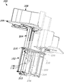
- FIG. 12 is a perspective view of the support column and interior of the base.
- FIG. 13 is a top perspective view of the interior of the base.
- FIG. 14 is a perspective view of the baffle assembly.
- FIG. 15 is a partial top perspective view of the interior of the base showing exemplary cable connections.
- FIG. 16 is a schematic for a single-unit workstation.
- FIG. 17 is a schematic for a triple-unit workstation.
- FIG. 18 is a schematic for a quad-unit workstation.
- FIGS. 1-3 show different embodiments of a workstation assembly system. Each assembly provides work space for one or more users.
- FIG. 1 shows a single-unit workstation 102 .
- FIG. 2 shows a triple-unit workstation 104 .
- FIG. 3 shows a quad-unit workstation 1 o 6 .
- the workstations can be used in office environments or public spaces (e.g., business, libraries, government buildings, etc.) in different combinations and configurations based on the available space.
- the workstations 102 , 104 , 106 can be placed along, and connected to, a wall or other vertical support, or can be freestanding units supported only by the floor.
- the single-unit 102 can be attached to the wall and the triple-unit and quad-unit workstations 104 , 106 can be freestanding. Additionally, multiple workstations 102 , 104 , 106 can be placed adjacent one another and optionally connected to form a chain of units.
- Each workstation 102 , 104 , 106 includes a base 110 , one or more support columns 112 , and one or more work surfaces 114 .
- the quad-unit workstation 106 can include two bases 110 that are connected.
- Each work surface 114 is connected to a support column 112 so that the work surface 114 extends from the support column 112 in a cantilevered fashion.
- the illustrated work surfaces 114 are each supported by a single support column 112 .
- the support column 112 can be height adjustable, and an actuator can be provided to allow a user to raise and lower the support column 112 to adjust the height of the work surface 114 .
- the height adjustment can include a manual raise/lower mechanism or can be electrically powered.
- screens 116 can be connected to the work surfaces 114 .
- the screens 116 can extend vertically upward between the different work surfaces 114 .
- the screens 116 can have different shapes, and may include tackable surfaces, writable white board or include various displays, such as a display monitor or projection surface.
- the screens can be linear along the longitudinal length, or curved, or combinations thereof.
- the screens 116 can also be configured with a contour to mate with an edge of the work surface 114 , including a curved shape.
- the workstations 102 , 104 , 106 can have different exterior finishes.
- the finishes can include different colors, textures (e.g., smooth, rough, glossy, matte, etc.), and patterns (e.g. wood grain, stone, etc.). These finishes can be achieved by using natural materials or engineered materials such as laminates.
- the work surfaces 114 can be made of a variety of materials, including without limitation, MDF, chipboard, glass-filled polyurethane, and combinations thereof.
- the various support components may be made of various metals and plastics, including steel and aluminum.
- FIG. 4 shows an embodiment of a 3-unit workstation 200 having a base 202 , three height adjustable support columns 204 , and three work surfaces 206 .
- the support columns 204 extend into and are supported by the base 202 . At least a portion of the support columns 204 move to adjust the height of the work surfaces 206 relative to the base 202 .
- Each support column 204 is independently moveable.
- the work surfaces 206 extend from the respective support columns 204 in a cantilever fashion. Screens 208 are connected to respective work surfaces 206 .
- the base 202 is configured to be positioned on a floor to support the workstation 200 .
- the base 202 includes an upper plate 210 , a lower plate 212 , and one or more interior plates 214 .
- the upper plate 210 , lower plate 212 , and interior plates 214 can provide the support and structure of the base 202 , and permit different interior components to be connected thereto. In the illustrated embodiment, three interior panels 214 are used.
- the upper plate 210 , lower plate 212 , and interior plates 214 can each be formed from one or more pieces. In certain aspects the plates 210 , 212 , 214 can be formed from sheet metal, although other materials can be used.
- the plates 210 , 212 , 214 can be connected to form a rigid structure using fasteners or a joining process such as welding.
- An upper cover 216 and outer walls 218 can be connected to one or more of the plates 210 , 212 , 214 to form an exterior housing.
- the upper cover 216 and outer walls 218 can have different finishes to provide a desired aesthetic.
- the upper cover 216 and outer walls 218 can each be formed from one or more pieces.
- the support column 204 can include an upper column 220 and a lower column 222 .
- the lower column 222 is fixed to the base 202 , and the upper column 220 moves relative to the base 202 and the lower column 222 to adjust the height of the work surface 206 .
- the upper column 220 can be positioned at least partially inside of the lower column 222 and move in a telescopic manner.
- the height adjustment can be achieved by an electromechanical screw with a servo motor or as various hydraulic and/or pneumatic devices.
- a height adjustment switch can be provided so that a user can control the movement of the support column 204 .
- the switch can be positioned on the base 202 , the support column 204 , or the work surface 206 .
- a control unit 224 can be mounted to the bottom of the work surface 206 .
- the control unit 224 is connected to the height adjustment switch and controls the movement of a motor to raise and lower the upper column 220 .
- an outlet 226 is accessible to a user on or through the upper surface of the work surface 206 .
- the outlet 226 can extend through the work surface 206 and can be flush or recess mounted with the upper surface.
- the outlet 226 can include one or more AC-style outlets (e.g., 3-prong outlets) and one or more DC-style outlets (e.g., USB ports).
- AC-style outlets e.g., 3-prong outlets
- DC-style outlets e.g., USB ports.
- FIGS. 7 and 8 show certain aspects of an internal cable management system for the work station 200 .
- the cable management system includes an upper bracket 228 connected to the top of the upper column 220 , a lower bracket 230 connected to the base 202 , and a cable track 232 .
- the cable track 232 includes an outer cover 234 and a cable guide 236 .
- One or more cables can be guided into the base 202 through the support column 204 and/or through the cable track 232 .
- the upper bracket 228 includes a connector plate 238 having various openings and bosses that are used to receive fasteners to connect the upper bracket 228 to the upper column 220 and the work surface 206 .
- a u-shaped projection 240 extends from each side of the connector plate 238 and is configured to rest on an upper edge of the upper column 220 .
- a front wall 242 extends in front of the connector plate 238 .
- Tabs 244 extend from the front wall 242 .
- the tabs 244 can connect the cable guide 236 to the upper bracket 228 .
- a pair of arms 246 extend from the outer edges of the front wall 242 .
- the arms 246 are curved or angled toward each other and include a hooked portion at each end.
- the lower bracket 230 includes a front fork 248 and a pair of flexible side tabs 250 that are used to connect the lower bracket 230 to the upper plate 210 or outer cover 216 of the base 202 .
- a yoke 252 is configured to receive a portion of cable track 232 and provide a smooth sliding surface for the movement of the cable track 232 .
- the cable track 232 is connected to the upper bracket 228 and is guided by the lower bracket 230 as the upper column 220 moves relative to the lower column 222 and the base 202 .
- the outer cover 234 has a pyramidal configuration with a rounded top. Resilient tines 254 extend toward the cable guide 236 and are used to connect the outer cover 234 to the cable guide 236 .
- the outer cover 234 can have a finish that matches or is complimentary to the finish of one or more of the base 202 and the work surface 206 to provide a consistent aesthetic appearance.
- the cable guide 236 includes a first end 256 that is connected to the upper bracket 228 and a second end 258 that is connected to the upper plate 210 of the base 202 .
- the first end 256 and the second end 258 each include one or more mounting features that fasten the cable guide 236 .
- the cable guide 236 can be clipped or snap fit to the upper bracket 228 and to the top plate 210 .
- One or more sets of outer openings 260 are formed in the cable guide 236 . These openings 260 can receive straps (e.g., cable ties, Velcro, etc.) that fasten conductors to the cable guide 236 .
- the cable guide 236 can include a flexible material so that the cable guide 236 can bend as it moves with the upper column as best shown in FIGS. 4 and 12 . As shown in FIG. 12 , the second end 258 of the cable guide is spaced from the support column 204 so that a loop is formed to support the cables and keep them from tangling.
- the internal cable management can also include a baffle assembly 262 that has one or more baffle plates 264 positioned in the base 202 .
- a baffle assembly 262 that has one or more baffle plates 264 positioned in the base 202 .
- two baffles 264 are connected to one of the interior plates 214 and have a substantially Z-shaped configuration.
- the baffles 264 extend toward one another and into the center of the base 202 .
- the configuration and positioning of the baffles 264 forms a first pocket 266 near the center of the base and a second pocket 268 adjacent one of the interior plates.
- the second pocket 268 can be positioned near one or more power supply components positioned in the base 202 and protect cables connected thereto. Extra non-moving cables can also be stored or routed through the first pocket 266 .
- the baffles 264 also help prevent the cable guides 236 of each column from interfering with one another as they move.
- the cables 270 connected to the user power supply (AC) and to the motors for the support column (DC) are routed down the center of the base 202 where they exit the cable tracks.
- the cables exit the first pocket 266 into the second pocket 268 through a space between the baffles 264 and extend to either an AC splitter or a DC splitter.
- the baffle assembly 262 can be formed from one baffle plate 264 or more than two baffle plates 264 .
- the size, shape, and configuration of the baffle assembly 262 can be adjusted based on the size, shape, and configuration of the base as well as the cable management requirements.
- triple-unit workstation 200 is shown and described in detail, these features can be applied to the single unit workstation 100 and the quad-unit workstation 104 .
- FIGS. 16-18 show exemplary schematics of the power supply components that can be incorporated into the different workstations 100 , 102 , 104 .
- FIG. 16 shows am exemplary schematic for a single-unit workstation.
- An AC power input 300 is connected to an AC splitter 302 .
- the AC splitter 302 branches power along two or more outputs.
- FIG. 16 shows a primary path 304 and a secondary path 306 .
- the primary path 304 extends to an AC/DC converter 308 .
- the AC/DC converter 308 converts the AC input to a DC output that is sent to a motor controller 310 .
- the motor controller 310 includes a DC power input and a control input.
- the control input receives a signal from a switch 312 activated by a user.
- the signal indicates a raise or lower command for the support column. Based on the command, a voltage signal is sent to the motor through a motor cable 314 to raise or lower the support column.
- the secondary path 306 sends power to a user access point 316 (e.g., the outlet shown in FIG. 6 ).
- the AC splitter can contain two distinct types of outlets.
- the first type of outlet 318 can be a 1-15R (two prong) or 5-15R (three prong) type outlet and the second type of outlet 320 can be a C13 style outlet.
- Other types of outlets, including bayonet style, pin outlets, or 3 phase outlets can also be used.
- the second type of outlet 320 has a different style connection than the power input 300 .
- the power input 300 includes a 5-15P plug and the outlets 320 for the secondary path 306 utilize a C13 outlet and a C14 plug.
- FIG. 17 shows an exemplary schematic for a triple-unit workstation.
- An AC power input 400 is connected to an AC splitter 402 .
- the AC splitter 402 branches power along a primary path 404 and three secondary paths 406 .
- the output for the primary path 404 includes a first type of outlet 408 and the output for the secondary paths 406 includes a second type of outlet 410 distinct from the first type of outlet 408 .
- the power input 400 includes a first style of plug that is configured to engage a first type of outlet (e.g., a 3-prong wall outlet).
- the secondary paths 406 each include a second style of plug that different from the power input 400 .
- the first style of plug may be a NEMA type connector (e.g., NEMA 5-15-P), while the second style of plug may be an IEC type connector (e.g., IEC 320 C13/C14).
- NEMA type connector e.g., NEMA 5-15-P
- IEC type connector e.g., IEC 320 C13/C14
- the primary path 404 and each secondary path 406 may include the same style of plugs.
- the primary path 404 and the secondary paths 406 may include different styles of plugs.
- the AC splitter 402 may also include one or more additional outlets, such as NEMA type outlets.
- the primary path 404 extends to an AC/DC converter 412 .
- the AC/DC converter 412 converts the AC input to a DC output that is sent to a DC splitter 414 .
- the DC splitter 414 branches the DC power along three output paths, with each path connected to a motor controller 416 .
- the motor controller 416 includes a DC power input and a control input.
- the control input receives a signal from a switch 418 activated by a user.
- the signal indicates a raise or lower command for the associated support column. Based on the command, a voltage signal is sent to the motor through a motor cable 420 to raise or lower the support column.
- Each of the motor controllers 416 and associated motors are operable independently, but can also be used at the same time (e.g., one work surface can be raised at the same time another work surface is being lowered).
- the motor controllers 416 and the motors all receive power from a single, shared power source via the AC splitter 402 .
- the three secondary paths 406 send power to a respective user access point 422 (e.g., the outlet shown in FIG. 6 ).
- each access point 422 may include one or more AC-style outlets and one or more DC-style outlets.
- the multiple outlets on each access point 422 can be daisy-chained from the AC splitter 402 (which also includes multiple outlets).
- the workstation can be connected to a wall outlet to power the motor controllers 416 and the user access points 422 using a single plug.
- FIG. 18 an exemplary schematic for a quad-unit workstation.
- An AC power input 500 is connected to an AC splitter 502 .
- the AC splitter 502 branches power along a primary path 504 and four secondary paths 506 . Similar to the three-unit workstation ( FIG. 17 ), the power input 500 includes a first style of plug, while the secondary paths 5 o 6 include a second style of plug.
- the primary path 504 extends to an AC/DC converter 512 .
- the AC/DC converter 512 converts the AC input to a DC output that is sent to a DC splitter 514 .
- the DC splitter 514 branches the DC power along four output paths, with each path connected to a motor controller 516 .
- the motor controller 516 includes a DC power input and a control input.
- the control input receives a signal from a switch 518 activated by a user.
- the signal indicates a raise or lower command for the support column.
- a voltage signal is sent to the motor through a motor cable 520 to raise or lower the support column.
- the four secondary paths 5 o 6 send power to a respective user access point 522 (e.g., the outlet shown in FIG. 6 ).
- the terms “front,” “rear,” “upper,” “lower,” “upwardly,” “downwardly,” and other orientational descriptors are intended to facilitate the description of the exemplary embodiments of the present disclosure, and are not intended to limit the structure of the exemplary embodiments of the present disclosure to any particular position or orientation.
- Terms of degree, such as “substantially” or “approximately” are understood by those of ordinary skill to refer to reasonable ranges outside of the given value, for example, general tolerances associated with manufacturing, assembly, and use of the described embodiments.
Abstract
Description
Claims (20)
Priority Applications (1)
| Application Number | Priority Date | Filing Date | Title |
|---|---|---|---|
| US17/224,817 US11503905B2 (en) | 2020-04-09 | 2021-04-07 | Workstation assembly |
Applications Claiming Priority (2)
| Application Number | Priority Date | Filing Date | Title |
|---|---|---|---|
| US202063007763P | 2020-04-09 | 2020-04-09 | |
| US17/224,817 US11503905B2 (en) | 2020-04-09 | 2021-04-07 | Workstation assembly |
Publications (2)
| Publication Number | Publication Date |
|---|---|
| US20210315378A1 US20210315378A1 (en) | 2021-10-14 |
| US11503905B2 true US11503905B2 (en) | 2022-11-22 |
Family
ID=78005524
Family Applications (1)
| Application Number | Title | Priority Date | Filing Date |
|---|---|---|---|
| US17/224,817 Active US11503905B2 (en) | 2020-04-09 | 2021-04-07 | Workstation assembly |
Country Status (3)
| Country | Link |
|---|---|
| US (1) | US11503905B2 (en) |
| EP (1) | EP4132325A1 (en) |
| WO (1) | WO2021207383A1 (en) |
Cited By (1)
| Publication number | Priority date | Publication date | Assignee | Title |
|---|---|---|---|---|
| USD1018145S1 (en) * | 2020-10-14 | 2024-03-19 | MillerKnoll, Inc. | Height adjustable workstation |
Citations (65)
| Publication number | Priority date | Publication date | Assignee | Title |
|---|---|---|---|---|
| US3559352A (en) | 1969-03-12 | 1971-02-02 | Beatrice Foods Co | Interior space divider arrangement |
| US4248477A (en) | 1978-08-25 | 1981-02-03 | Elbert Netters | Furniture construction |
| US4600173A (en) * | 1983-04-22 | 1986-07-15 | C.O.M. Cooperativa Operai Metallurgici S.C.R.L. | Load-bearing bar for office furniture |
| US4604956A (en) | 1984-05-18 | 1986-08-12 | Wright Line Inc. | Adjustment mechanism for work station |
| US4604955A (en) | 1981-10-03 | 1986-08-12 | Willy Fleischer Metallwarenfabrik Gmbh & Co. | Height-adjustable table for work places with video screen |
| US4646655A (en) | 1984-06-11 | 1987-03-03 | Claude Robolin | Data processing work station |
| US4762072A (en) * | 1986-10-07 | 1988-08-09 | Westinghouse Electric Corp. | Desk and space dividing wall panel assembly |
| US4838175A (en) * | 1986-01-23 | 1989-06-13 | Hauville Francois P | Laboratory table |
| US4852500A (en) * | 1987-03-18 | 1989-08-01 | Herman Miller, Inc. | Integrated computer implement work area |
| US4879955A (en) * | 1987-06-23 | 1989-11-14 | Planmoebel Eggersman Gmbh & Co. Kg | Office workstation |
| US4941412A (en) * | 1987-08-14 | 1990-07-17 | Ernst Fischer Gmbh & Co. | Modular working table |
| US5083838A (en) | 1990-09-14 | 1992-01-28 | Maxwell Jr Joseph A | Seating cluster for airport waiting and similar areas |
| US5220871A (en) * | 1989-02-07 | 1993-06-22 | Steelcase Inc. | Modular furniture |
| US5237935A (en) * | 1988-03-01 | 1993-08-24 | Herman Miller, Inc. | Work environment system |
| US5357874A (en) * | 1992-07-30 | 1994-10-25 | Abco Office Furniture Inc. | Channel assembly with snap-in insert |
| US5394809A (en) * | 1993-05-03 | 1995-03-07 | Steelcase Inc. | Adjustable height table |
| US5606920A (en) * | 1995-06-08 | 1997-03-04 | Haworth, Inc. | Linkable modular table |
| US5831211A (en) * | 1996-04-04 | 1998-11-03 | Clifford W. Gartung | Variable-type cable management and distribution system |
| US5901513A (en) * | 1997-06-04 | 1999-05-11 | Rosemount Office Systems, Inc. | Lay in cable channel for modular office systems |
| US6029587A (en) * | 1998-06-05 | 2000-02-29 | Knoll, Inc. | Offset support leg for an adjustable height desk |
| US6082840A (en) * | 1998-04-15 | 2000-07-04 | Steelcase Development Inc. | Freestanding furniture system |
| US6086028A (en) * | 1999-05-26 | 2000-07-11 | Pfister; Joel W. | Table leg with cable management system |
| US6145448A (en) | 1999-04-30 | 2000-11-14 | Haworth, Inc. | Furniture arrangement having a slidable intermediate table |
| US6182579B1 (en) | 1999-09-06 | 2001-02-06 | Chien-Kuo Chang | Office desk with multiple trays pivotally connected thereto |
| US6202567B1 (en) * | 1994-06-10 | 2001-03-20 | Krueger International, Inc. | Modular table system with cable management |
| US6286441B1 (en) | 1999-04-30 | 2001-09-11 | Steelcase Development Corporation | Height adjustable work surface and control therefor |
| US6293506B1 (en) * | 1998-05-01 | 2001-09-25 | Ditto Sales, Inc. | Table leg wire management apparatus |
| US6327983B1 (en) * | 1999-03-03 | 2001-12-11 | Steelcase Development Corporation | Conference table with central utility system |
| US6352037B1 (en) * | 2000-02-28 | 2002-03-05 | Suspa Incorporated | Position sensor holder and cover for motor drive unit |
| US6364128B1 (en) * | 1999-12-30 | 2002-04-02 | Decade Industries, Inc. | Wire cover for electronic equipment stand and furniture |
| US20020043183A1 (en) * | 2000-10-13 | 2002-04-18 | Insalaco Robert W. | Table |
| US20020046852A1 (en) * | 2000-05-02 | 2002-04-25 | King Steven Jay | Flexible raceway arrangement for cabling |
| US6398149B1 (en) * | 2001-01-16 | 2002-06-04 | Ortronics, Inc. | Cable management system with adjustable cable spools |
| US6416336B1 (en) * | 2001-05-07 | 2002-07-09 | Modelec S.A. | Electrical connection tower as a push-in part |
| US20020145088A1 (en) * | 2001-03-08 | 2002-10-10 | Woodhead Industries, Inc. (A Delaware Corporation) | Workstation with adjustable height frame |
| US6786161B2 (en) | 2002-04-18 | 2004-09-07 | Center For Discovery | Table with multiple height adjustable stations |
| US6912960B2 (en) | 2003-06-02 | 2005-07-05 | Sing Bee Enterprise Co., Ltd. | Detachable computer desk |
| US20070204537A1 (en) * | 2006-03-03 | 2007-09-06 | Fisher Hamilton L.L.C. | Modular Furniture System |
| US20080289545A1 (en) | 2007-05-25 | 2008-11-27 | Unifor S.P.A. | Workstation System and Workstation with Multiple, Adjustable Height, Work Tops |
| US20090078171A1 (en) * | 2005-04-14 | 2009-03-26 | Linak A/S | Article of furniture, in particular a sitting/standing table |
| US20090179123A1 (en) | 2008-01-14 | 2009-07-16 | Mayline Company, Llc | Single Column Pedestal for a Height-Adjustable Work Station |
| US7626120B1 (en) * | 2007-05-01 | 2009-12-01 | Premier Manufacturing Group, Inc. | Pop-up power and communication outlet apparatus for use with a table, desk or similar article |
| US20090293773A1 (en) * | 2008-05-28 | 2009-12-03 | Steelcase Inc. | Worksurface assembly |
| US7634967B1 (en) * | 2005-10-11 | 2009-12-22 | Chip Albright | Laboratory work station accessory |
| US20100024687A1 (en) * | 2006-05-09 | 2010-02-04 | Preiss Juergen | Furniture with cable channel |
| US20140208986A1 (en) | 2013-01-25 | 2014-07-31 | Léon DesRoches | Workstation having automated and powered height, depth and rotational adjusters |
| US20140238277A1 (en) * | 2013-02-22 | 2014-08-28 | Novartis Institutes For Biomedical Research, Inc. | Modular laboratory workbench |
| US20140312754A1 (en) | 2013-03-15 | 2014-10-23 | Herman Miller, Inc. | Worksurface assembly having cantilevered, vertically adjustable worksurfaces |
| US20140331901A1 (en) * | 2013-05-09 | 2014-11-13 | Hamilton Scientific Llc | Mobile furniture system |
| US8893628B2 (en) | 2013-03-04 | 2014-11-25 | Watson Furniture Group, Inc. | Dispatch desk with focal length adjustability |
| US20140360413A1 (en) | 2013-06-06 | 2014-12-11 | Peter Schenk | Active workstation apparatus and method |
| US20150083028A1 (en) * | 2013-09-26 | 2015-03-26 | Bedcolab, Ltd. | Systems And Methods For Improved Modular Laboratory Furniture |
| US20160360879A1 (en) * | 2015-06-14 | 2016-12-15 | Assa Group, Inc., d/b/a Enwork | Height adjustable desk system |
| US20160360897A9 (en) | 2010-09-16 | 2016-12-15 | Kids Ii, Inc. | Motion device for children |
| US20170164731A1 (en) | 2015-12-11 | 2017-06-15 | Herman Miller, Inc. | Workspace assembly |
| US9737142B2 (en) | 2013-03-20 | 2017-08-22 | Choong Chul CHO | Furniture system and method for arranging the same |
| US9781996B1 (en) * | 2015-09-25 | 2017-10-10 | Amanda Thompson | Computerized desk with a touch screen |
| US20170324230A1 (en) * | 2016-05-09 | 2017-11-09 | Evoque Group Llc D/B/A Clear Design | Power and data bridge |
| US20180064243A1 (en) | 2016-09-06 | 2018-03-08 | Vitra Patente Ag | Furniture composition with height-adjustable partition |
| US20180090915A1 (en) * | 2016-09-26 | 2018-03-29 | Norman R. Byrne | Cord system for height-adjustable furniture |
| US9936802B1 (en) * | 2015-10-01 | 2018-04-10 | Baker Manufacturing Company, Inc. | Height adjustable table |
| US9999295B1 (en) | 2017-04-28 | 2018-06-19 | Evans Consoles Corporation | Console and console support structure |
| US10004329B2 (en) | 2016-07-22 | 2018-06-26 | Cooper Technologies Company | Workstation with cable containment |
| DE102017109188A1 (en) | 2017-04-28 | 2018-10-31 | Knürr Technical Furniture GmbH | A workplace arrangement |
| DE102020127202A1 (en) * | 2019-10-15 | 2021-04-15 | Squaregrove, LLC dba UPLIFT Desk | Adjustable power and data rail for tables or desks |
-
2021
- 2021-04-07 WO PCT/US2021/026219 patent/WO2021207383A1/en unknown
- 2021-04-07 EP EP21785526.1A patent/EP4132325A1/en active Pending
- 2021-04-07 US US17/224,817 patent/US11503905B2/en active Active
Patent Citations (66)
| Publication number | Priority date | Publication date | Assignee | Title |
|---|---|---|---|---|
| US3559352A (en) | 1969-03-12 | 1971-02-02 | Beatrice Foods Co | Interior space divider arrangement |
| US4248477A (en) | 1978-08-25 | 1981-02-03 | Elbert Netters | Furniture construction |
| US4604955A (en) | 1981-10-03 | 1986-08-12 | Willy Fleischer Metallwarenfabrik Gmbh & Co. | Height-adjustable table for work places with video screen |
| US4600173A (en) * | 1983-04-22 | 1986-07-15 | C.O.M. Cooperativa Operai Metallurgici S.C.R.L. | Load-bearing bar for office furniture |
| US4604956A (en) | 1984-05-18 | 1986-08-12 | Wright Line Inc. | Adjustment mechanism for work station |
| US4646655A (en) | 1984-06-11 | 1987-03-03 | Claude Robolin | Data processing work station |
| US4838175A (en) * | 1986-01-23 | 1989-06-13 | Hauville Francois P | Laboratory table |
| US4762072A (en) * | 1986-10-07 | 1988-08-09 | Westinghouse Electric Corp. | Desk and space dividing wall panel assembly |
| US4852500A (en) * | 1987-03-18 | 1989-08-01 | Herman Miller, Inc. | Integrated computer implement work area |
| US4879955A (en) * | 1987-06-23 | 1989-11-14 | Planmoebel Eggersman Gmbh & Co. Kg | Office workstation |
| US4941412A (en) * | 1987-08-14 | 1990-07-17 | Ernst Fischer Gmbh & Co. | Modular working table |
| US5237935A (en) * | 1988-03-01 | 1993-08-24 | Herman Miller, Inc. | Work environment system |
| US5220871A (en) * | 1989-02-07 | 1993-06-22 | Steelcase Inc. | Modular furniture |
| US5083838A (en) | 1990-09-14 | 1992-01-28 | Maxwell Jr Joseph A | Seating cluster for airport waiting and similar areas |
| US5357874A (en) * | 1992-07-30 | 1994-10-25 | Abco Office Furniture Inc. | Channel assembly with snap-in insert |
| US5394809A (en) * | 1993-05-03 | 1995-03-07 | Steelcase Inc. | Adjustable height table |
| US6202567B1 (en) * | 1994-06-10 | 2001-03-20 | Krueger International, Inc. | Modular table system with cable management |
| US5606920A (en) * | 1995-06-08 | 1997-03-04 | Haworth, Inc. | Linkable modular table |
| US5831211A (en) * | 1996-04-04 | 1998-11-03 | Clifford W. Gartung | Variable-type cable management and distribution system |
| US5901513A (en) * | 1997-06-04 | 1999-05-11 | Rosemount Office Systems, Inc. | Lay in cable channel for modular office systems |
| US6082840A (en) * | 1998-04-15 | 2000-07-04 | Steelcase Development Inc. | Freestanding furniture system |
| US6293506B1 (en) * | 1998-05-01 | 2001-09-25 | Ditto Sales, Inc. | Table leg wire management apparatus |
| US6029587A (en) * | 1998-06-05 | 2000-02-29 | Knoll, Inc. | Offset support leg for an adjustable height desk |
| US6327983B1 (en) * | 1999-03-03 | 2001-12-11 | Steelcase Development Corporation | Conference table with central utility system |
| US6145448A (en) | 1999-04-30 | 2000-11-14 | Haworth, Inc. | Furniture arrangement having a slidable intermediate table |
| US6286441B1 (en) | 1999-04-30 | 2001-09-11 | Steelcase Development Corporation | Height adjustable work surface and control therefor |
| US6086028A (en) * | 1999-05-26 | 2000-07-11 | Pfister; Joel W. | Table leg with cable management system |
| US6182579B1 (en) | 1999-09-06 | 2001-02-06 | Chien-Kuo Chang | Office desk with multiple trays pivotally connected thereto |
| US6364128B1 (en) * | 1999-12-30 | 2002-04-02 | Decade Industries, Inc. | Wire cover for electronic equipment stand and furniture |
| US6352037B1 (en) * | 2000-02-28 | 2002-03-05 | Suspa Incorporated | Position sensor holder and cover for motor drive unit |
| US20020046852A1 (en) * | 2000-05-02 | 2002-04-25 | King Steven Jay | Flexible raceway arrangement for cabling |
| US20020043183A1 (en) * | 2000-10-13 | 2002-04-18 | Insalaco Robert W. | Table |
| US6398149B1 (en) * | 2001-01-16 | 2002-06-04 | Ortronics, Inc. | Cable management system with adjustable cable spools |
| US20020145088A1 (en) * | 2001-03-08 | 2002-10-10 | Woodhead Industries, Inc. (A Delaware Corporation) | Workstation with adjustable height frame |
| US6416336B1 (en) * | 2001-05-07 | 2002-07-09 | Modelec S.A. | Electrical connection tower as a push-in part |
| US6786161B2 (en) | 2002-04-18 | 2004-09-07 | Center For Discovery | Table with multiple height adjustable stations |
| US6912960B2 (en) | 2003-06-02 | 2005-07-05 | Sing Bee Enterprise Co., Ltd. | Detachable computer desk |
| US20090078171A1 (en) * | 2005-04-14 | 2009-03-26 | Linak A/S | Article of furniture, in particular a sitting/standing table |
| US7634967B1 (en) * | 2005-10-11 | 2009-12-22 | Chip Albright | Laboratory work station accessory |
| US20070204537A1 (en) * | 2006-03-03 | 2007-09-06 | Fisher Hamilton L.L.C. | Modular Furniture System |
| US20100024687A1 (en) * | 2006-05-09 | 2010-02-04 | Preiss Juergen | Furniture with cable channel |
| US7626120B1 (en) * | 2007-05-01 | 2009-12-01 | Premier Manufacturing Group, Inc. | Pop-up power and communication outlet apparatus for use with a table, desk or similar article |
| US20080289545A1 (en) | 2007-05-25 | 2008-11-27 | Unifor S.P.A. | Workstation System and Workstation with Multiple, Adjustable Height, Work Tops |
| US20090179123A1 (en) | 2008-01-14 | 2009-07-16 | Mayline Company, Llc | Single Column Pedestal for a Height-Adjustable Work Station |
| US20090293773A1 (en) * | 2008-05-28 | 2009-12-03 | Steelcase Inc. | Worksurface assembly |
| US20160360897A9 (en) | 2010-09-16 | 2016-12-15 | Kids Ii, Inc. | Motion device for children |
| US20140208986A1 (en) | 2013-01-25 | 2014-07-31 | Léon DesRoches | Workstation having automated and powered height, depth and rotational adjusters |
| US20140238277A1 (en) * | 2013-02-22 | 2014-08-28 | Novartis Institutes For Biomedical Research, Inc. | Modular laboratory workbench |
| US8893628B2 (en) | 2013-03-04 | 2014-11-25 | Watson Furniture Group, Inc. | Dispatch desk with focal length adjustability |
| US20140312754A1 (en) | 2013-03-15 | 2014-10-23 | Herman Miller, Inc. | Worksurface assembly having cantilevered, vertically adjustable worksurfaces |
| US9737142B2 (en) | 2013-03-20 | 2017-08-22 | Choong Chul CHO | Furniture system and method for arranging the same |
| US20140331901A1 (en) * | 2013-05-09 | 2014-11-13 | Hamilton Scientific Llc | Mobile furniture system |
| US20140360413A1 (en) | 2013-06-06 | 2014-12-11 | Peter Schenk | Active workstation apparatus and method |
| US20170295930A1 (en) * | 2013-09-26 | 2017-10-19 | Bedcolab, Ltd. | Modular laboratory furniture assembly |
| US20150083028A1 (en) * | 2013-09-26 | 2015-03-26 | Bedcolab, Ltd. | Systems And Methods For Improved Modular Laboratory Furniture |
| US20160360879A1 (en) * | 2015-06-14 | 2016-12-15 | Assa Group, Inc., d/b/a Enwork | Height adjustable desk system |
| US9781996B1 (en) * | 2015-09-25 | 2017-10-10 | Amanda Thompson | Computerized desk with a touch screen |
| US9936802B1 (en) * | 2015-10-01 | 2018-04-10 | Baker Manufacturing Company, Inc. | Height adjustable table |
| US20170164731A1 (en) | 2015-12-11 | 2017-06-15 | Herman Miller, Inc. | Workspace assembly |
| US20170324230A1 (en) * | 2016-05-09 | 2017-11-09 | Evoque Group Llc D/B/A Clear Design | Power and data bridge |
| US10004329B2 (en) | 2016-07-22 | 2018-06-26 | Cooper Technologies Company | Workstation with cable containment |
| US20180064243A1 (en) | 2016-09-06 | 2018-03-08 | Vitra Patente Ag | Furniture composition with height-adjustable partition |
| US20180090915A1 (en) * | 2016-09-26 | 2018-03-29 | Norman R. Byrne | Cord system for height-adjustable furniture |
| US9999295B1 (en) | 2017-04-28 | 2018-06-19 | Evans Consoles Corporation | Console and console support structure |
| DE102017109188A1 (en) | 2017-04-28 | 2018-10-31 | Knürr Technical Furniture GmbH | A workplace arrangement |
| DE102020127202A1 (en) * | 2019-10-15 | 2021-04-15 | Squaregrove, LLC dba UPLIFT Desk | Adjustable power and data rail for tables or desks |
Non-Patent Citations (6)
| Title |
|---|
| Byrne, "Byrne Interlink ®", webpage: https://www.byrne.com/byrneinterlink, Copyright 2020, (3 Pages). |
| Byrne, "Interlink iQ 2.0" Brochure from 2019, (2 Pages). |
| Byrne, "Twine ®", Brochure from 2019, (2 Pages). |
| Dekko, "DaisyLink System ™", Brochure from 2020 (3 Pages). |
| Dekko, "Perimeter System", Brochure from 2020 (4 Pages). |
| International Search Report with Written Opinion for related Application No. PCT/US2021/026219 dated Jul. 9, 2021 (16 Pages). |
Cited By (2)
| Publication number | Priority date | Publication date | Assignee | Title |
|---|---|---|---|---|
| USD1018145S1 (en) * | 2020-10-14 | 2024-03-19 | MillerKnoll, Inc. | Height adjustable workstation |
| USD1018144S1 (en) * | 2020-10-14 | 2024-03-19 | MillerKnoll, Inc. | Height adjustable workstation |
Also Published As
| Publication number | Publication date |
|---|---|
| EP4132325A1 (en) | 2023-02-15 |
| WO2021207383A1 (en) | 2021-10-14 |
| US20210315378A1 (en) | 2021-10-14 |
Similar Documents
| Publication | Publication Date | Title |
|---|---|---|
| US11944194B2 (en) | Frame type workstation configurations | |
| EP0639059B1 (en) | Desking system | |
| US8667908B2 (en) | Frame type table assemblies | |
| US6202567B1 (en) | Modular table system with cable management | |
| CA2437683C (en) | Electrical floor access module system | |
| US6397533B1 (en) | Tile and mounting arrangement for a wall panel system | |
| US5160188A (en) | Furniture stanchions with unitary power routing system | |
| US7278360B2 (en) | Variable configuration desk system with power and communication capability | |
| US8534752B2 (en) | Reconfigurable table assemblies | |
| US5103741A (en) | Modular furniture | |
| US20050268823A1 (en) | Conference table | |
| US6742307B2 (en) | Adjustable cubicle system | |
| EP0382514A2 (en) | Modular furniture | |
| EP0312369A2 (en) | Improvements in furniture | |
| US11503905B2 (en) | Workstation assembly | |
| WO2016175241A1 (en) | Top-panel-equipped furniture and furniture system | |
| US6848369B1 (en) | Workstation and power and telecommunication arrangement therefor | |
| EP0123972B1 (en) | Modular furniture | |
| US20200347592A1 (en) | Flexible workspace partition system | |
| US20080074015A1 (en) | Stacked cabinet structure with intermediate raceway | |
| CN102920218A (en) | Frame structure for display cabinet and display cabinet comprising same | |
| US11757267B1 (en) | Cable management system and modesty panel for height adjustable desk | |
| CA1233616A (en) | Office panelling system | |
| CA2539496C (en) | Knock-down panel partition system |
Legal Events
| Date | Code | Title | Description |
|---|---|---|---|
| FEPP | Fee payment procedure |
Free format text: ENTITY STATUS SET TO UNDISCOUNTED (ORIGINAL EVENT CODE: BIG.); ENTITY STATUS OF PATENT OWNER: LARGE ENTITY |
|
| AS | Assignment |
Owner name: GOLDMAN SACHS BANK USA, AS COLLATERAL AGENT, NEW YORK Free format text: SECURITY INTEREST;ASSIGNOR:HERMAN MILLER, INC.;REEL/FRAME:057452/0241 Effective date: 20210719 |
|
| STPP | Information on status: patent application and granting procedure in general |
Free format text: DOCKETED NEW CASE - READY FOR EXAMINATION |
|
| AS | Assignment |
Owner name: MILLERKNOLL, INC., MICHIGAN Free format text: CHANGE OF NAME;ASSIGNOR:HERMAN MILLER, INC.;REEL/FRAME:059360/0500 Effective date: 20211019 |
|
| AS | Assignment |
Owner name: HERMAN MILLER, INC., MICHIGAN Free format text: ASSIGNMENT OF ASSIGNORS INTEREST;ASSIGNORS:MATTHAI, JOHN THOMAS;KEYZER, PETER JAMES;SIGNING DATES FROM 20211101 TO 20220323;REEL/FRAME:059442/0295 |
|
| STPP | Information on status: patent application and granting procedure in general |
Free format text: NON FINAL ACTION MAILED |
|
| STPP | Information on status: patent application and granting procedure in general |
Free format text: RESPONSE TO NON-FINAL OFFICE ACTION ENTERED AND FORWARDED TO EXAMINER |
|
| STPP | Information on status: patent application and granting procedure in general |
Free format text: NOTICE OF ALLOWANCE MAILED -- APPLICATION RECEIVED IN OFFICE OF PUBLICATIONS |
|
| STCF | Information on status: patent grant |
Free format text: PATENTED CASE |