EP2280470B1 - Field element - Google Patents
Field element Download PDFInfo
- Publication number
- EP2280470B1 EP2280470B1 EP09742670.4A EP09742670A EP2280470B1 EP 2280470 B1 EP2280470 B1 EP 2280470B1 EP 09742670 A EP09742670 A EP 09742670A EP 2280470 B1 EP2280470 B1 EP 2280470B1
- Authority
- EP
- European Patent Office
- Prior art keywords
- field
- insertion holes
- magnet insertion
- circumferential direction
- field magnet
- Prior art date
- Legal status (The legal status is an assumption and is not a legal conclusion. Google has not performed a legal analysis and makes no representation as to the accuracy of the status listed.)
- Active
Links
Images


Classifications
-
- H—ELECTRICITY
- H02—GENERATION; CONVERSION OR DISTRIBUTION OF ELECTRIC POWER
- H02K—DYNAMO-ELECTRIC MACHINES
- H02K1/00—Details of the magnetic circuit
- H02K1/06—Details of the magnetic circuit characterised by the shape, form or construction
- H02K1/22—Rotating parts of the magnetic circuit
- H02K1/27—Rotor cores with permanent magnets
- H02K1/2706—Inner rotors
- H02K1/272—Inner rotors the magnetisation axis of the magnets being perpendicular to the rotor axis
- H02K1/274—Inner rotors the magnetisation axis of the magnets being perpendicular to the rotor axis the rotor consisting of two or more circumferentially positioned magnets
- H02K1/2753—Inner rotors the magnetisation axis of the magnets being perpendicular to the rotor axis the rotor consisting of two or more circumferentially positioned magnets the rotor consisting of magnets or groups of magnets arranged with alternating polarity
- H02K1/276—Magnets embedded in the magnetic core, e.g. interior permanent magnets [IPM]
- H02K1/2766—Magnets embedded in the magnetic core, e.g. interior permanent magnets [IPM] having a flux concentration effect
Definitions
- the present invention relates to a field element, and more particularly, to an embedded type field element.
- JP-A-2003-88015 describes an interior permanent magnet rotor capable of reducing cogging torque.
- the rotor includes a rotor core and four permanent magnets that are built and disposed in the rotor core. These permanent magnets are circularly disposed with a rotation axis being the center.
- An outer contour of the rotor core has a so-called petal shape in which the radius on both end sides of the permanent magnets is smaller than the radius on the center side of the permanent magnets in a circumferential direction with the rotation axis being the center.
- a magnetic field distribution of a magnetic flux density distribution is improved, so that the magnetic flux density distribution is made close to a sinusoidal distribution.
- US 2005/0200223 A1 discloses a permanent magnet rotating electric machine that comprises a stator having stator windings wound round a stator iron core and a permanent magnet rotor having a plurality of inserted permanent magnets in which the polarity is alternately arranged in the peripheral direction in the rotor iron core.
- the rotor iron core of the permanent magnets is composed of magnetic pole pieces, auxiliary magnetic poles, and a stator yoke, and furthermore has concavities formed on the air gap face of the magnetic pole pieces of the rotor iron core of the permanent magnets, gently tilting from the central part of the magnetic poles to the end thereof.
- US 2007/0126304 A1 discloses a rotary shaft having an outside diameter larger than the bore diameter of a rotary shaft insert hole of a rotor is inserted into the rotary shaft insert hole.
- a magnet insert hole is provided in a main magnetic pole of the rotor. Permanent magnets to are inserted into the magnet insert hole such that a gap is formed between the permanent magnets and the magnet insert hole.
- a semi-tubular rivet insert hole and interlocks elongated in the radial direction of the rotor are disposed radially outward of the magnet insert hole in the rotor.
- a semi-tubular rivet is inserted into the semi-tubular rivet insert hole such that a gap is formed between the semi-tubular rivet and the semi-tubular rivet insert hole. Passage holes, are provided in the auxiliary magnetic poles.
- JP 2001 178045 A discloses a magnet housing holes the cross section in the axial direction, of which is trapezoidal in shape, with its projected side facing toward the center are formed in a rotor core. Permanent magnets are embedded in the magnet housing holes. A notched portion, cut from end walls of the magnet housing holes in the direction of the outer circumference of the rotor core is formed in the portion of the rotor core, opposed to the end walls. Or a gap is formed between the end walls and the outer circumferential wall of the rotor core.
- An object of the present invention is therefore to provide a field element capable of easily measuring an air gap at both ends of the permanent magnets while reducing cogging torque.
- a field element includes: a plurality of field magnets (20, 21, 22); and a field element core (1) having a perimeter (10) exposed around a predetermined axis (P), and a plurality of field magnet insertion holes (30, 31, 33) disposed circularly around the axis, at least one of the plurality of field magnets is inserted into each of said at least one of said plurality of field magnet insertion holes, wherein: the at least one of the plurality of field magnets inserted into each of the plurality of field magnet insertion holes is disposed with magnetic pole surfaces of a single polarity facing the perimeter; one of the plurality of field magnet insertion holes and another of the plurality of field magnet insertion holes are adjacent to each other in a circumferential direction (D) with the axis being a center, where the magnetic pole surface of the at least one of the plurality of field magnets inserted into the one of the plurality of field magnet insertion holes and the magnetic pole surface of the at least one of the plurality
- each of the plurality of field magnet insertion holes has, at both ends in the circumferential direction (D), first cavity portions (31) on a side closer to the perimeter (10) than the at least one of the plurality of field magnets (21, 22) inserted thereinto;
- the field element core (1) further has second cavity portions (32) each disposed along the perimeter on the first position (101) side with respect to the first cavity portion, apart from the first cavity portion in the circumferential direction (D); and a point (11) on the perimeter at which the distance (R) turns from decreasing to increasing between the first position and the second position is positioned on a side closer to the second position in the circumferential direction than an end (321) on the first position side of the second cavity portion in the circumferential direction.
- a field element includes: a plurality of field magnets (20, 21, 22); and a field element core (1) having a perimeter (10) exposed around a predetermined axis (P), and a plurality of field magnet insertion holes (30, 31, 33) disposed circularly around the axis, at least one of the plurality of field magnets is inserted into each of said at least one of said plurality of field magnet insertion holes, wherein: the at least one of the plurality of field magnets inserted into each of the plurality of field magnet insertion holes is disposed with magnetic pole surfaces of a single polarity facing the perimeter; one of the plurality of field magnet insertion holes and another of the plurality of field magnet insertion holes are adjacent to each other in a circumferential direction (D) with the axis being a center, where the magnetic pole surface of the at least one of the plurality of field magnets inserted into the one of the plurality of field magnet insertion holes and the magnetic pole surface of the at least one
- the center of the one of the plurality of field magnet insertion holes in the circumferential direction (D) is positioned on the axis (P) side with respect to a straight line connecting both ends in the circumferential direction of the at least one of the plurality of field magnets inserted into the one of the plurality of field magnet insertion holes (30).
- a holding force of the at least one of the plurality of field magnets (20) is larger on an end portion side of the field magnet insertion hole in the circumferential direction than on the center side of the plurality of field magnet insertion holes (30) into which itself is inserted.
- an energy product of the at least one of the plurality of field magnets (20) is larger on an end portion side of the field magnet insertion hole in the circumferential direction than on the center side of the plurality of field magnet insertion holes (30) into which itself is inserted.
- the at least one of the plurality of field magnets includes a plurality of field magnets, the plurality of field magnets inserted into the one of the plurality of field magnet insertion holes (30) being adjacent to each other in the circumferential direction (D) or in a direction parallel to the axis (P).
- At least one of field magnets inserted into one field element insertion hole causes a field element core on a perimeter side of the field element insertion hole to function as one magnetic pole of the field element.
- Magnetic poles that the field magnet insertion holes adjacent to each other in the circumferential direction cause the field element cores on the perimeter side thereof have polarities different from each other.
- the first position is the center of the magnetic poles (magnetic pole center) and the second position is between the magnetic poles (between magnetic poles). The distance between the axis and the perimeter decreases from the first position toward the second position.
- a magnetroresistance increases due to a decrease in the distance, with the result that the waveform of the magnetic flux density generated on the surface of the perimeter by the field magnet can be made close to a sinusoidal wave that is minimized between magnetic poles and maximized at the magnetic pole center.
- the distance increases again between the magnetic poles.
- the magnetic flux density is small between the magnetic poles, and thus the waveform of the magnetic flux density is only slightly affected even when the magnetroresistance is reduced. Therefore, in a case where an armature opposed to the field element is provided in the direction parallel to the rotation axis, it is possible to reduce a gap (air gap) between the field element and the armature between the magnetic poles while making the waveform of the magnetic flux density close to a sinusoidal wave.
- the distance between the field element and the armature between the magnetic poles can be measured with ease. Accordingly, it is possible to increase the positions at which the distance between the field element and the armature is measured, and a relative position between the field element and the armature can be fixed with accuracy.
- the magnetroresistance increases due to a decrease of the distance in the region in which the distance decreases from the first position toward the second position, and then the magnetroresistance can be increased due to the second cavity portion in the region in which the distance increases toward the second position.
- an increase in magnetroresistance is decreased as closer to the first position.
- the magnetroresistance can be adjusted base on a decrease in distance at the position close to the first position, whereby it is possible to finely adjust the magnetroresistance.
- the first cavity portion and the second cavity portion are apart from each other, and thus the strength of the field element core can be enhanced.
- the magnetroresistance increases due to a decrease of the distance in the region in which the distance decreases from the first position toward the second position, and then the magnetroresistance can be increased due to the cavity portion in the region in which the distance increases toward the second position.
- an increase in magnetroresistance is reduced as closer to the first position.
- the magnetroresistance can be adjusted based on a decrease of the distance at the position close to the first position, whereby it is possible to finely adjust the magnetroresistance.
- the field magnets are tilted, toward the perimeter side, from the magnetic pole center to between the magnetic poles in one magnetic pole, and thus the magnetic flux density on the first position side can be enhanced. Accordingly, the magnetic flux density can be made closer to a sinusoidal wave.
- the demagnetization resistance can be enhanced.
- a high magnetic flux density can be generated at the center of the perimeter in the circumferential direction.
- an eddy current flowing through the surface of the field magnet can be reduced. Normally, demagnetization is more likely to occur along with a temperature rise of the field magnet. Therefore, the Joule heat can be reduced by reducing the eddy current, and accordingly the demagnetization resistance can be enhanced.
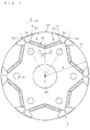
- FIG. 1 is a schematic cross-sectional view of a field element according to an embodiment of the present invention.
- FIG. 1 shows the schematic structure of the field element in cross section perpendicular to a rotation axis P.
- the field element includes a field element core 1 and a plurality of field magnets 20.
- the field element core 1 has a perimeter 10 exposed around the rotation axis P, a plurality of field magnet insertion holes 30 circularly disposed around the rotation axis P, cavity portions 32, a shaft hole 40, and holes 50 for bolts or pins.
- the shaft hole 40 is provided in a region including the rotation axis P while penetrating through the field element core 1 in a direction parallel to the rotation axis P. Note that the shaft hole 40 is not necessarily required. For example, the shaft hole 40 is not required in a mode in which end plates are provided to both ends of the field element core 1 in the direction parallel to the rotation axis P and a shaft is mounted to the end plates.
- the holes 50 are disposed, for example, circularly around the rotation axis P and penetrate through the field element core 1 in the direction parallel to the rotation axis P.
- a pin or bolt is inserted into the hole 50.
- the field element core 1 is sandwiched between the end plates from both sides, and the entirety is fixed with pins or bolts through the holes 50.
- the holes 50 are not necessarily required as long as there is provided a mode in which, for example, the field element core 1 and the end plates are fixed by welding.
- the plurality of field magnet insertion holes 30 are circularly disposed around the rotation axis P. At least one field magnet is inserted into each of the field magnet insertion holes 30.
- FIG. 1 illustrates a mode in which two field magnets 21 and 22 are inserted into each of the field magnet insertion holes 30.
- the field magnets 21 and 22 cause the field element core 1 on the perimeter 10 side to function as magnetic poles. Note that in the description below, a pair of field magnets 21 and 22 inserted into one field magnet insertion hole 30 is referred to as the field magnet 20.
- Magnetic pole surfaces of the field magnet 20 are disposed such that single magnetic pole faces the perimeter side.
- the field magnets 21 and 22 respectively inserted into each of the field magnet insertion holes 30 are disposed with the magnetic pole surfaces of the same polarity facing the perimeter 10.
- Polarities are different from each other between the magnetic pole surfaces on which the field magnets 21 and 22 that are inserted into one of a pair of adjacent field magnet insertion holes 30 in a circumferential direction D face the perimeter 10 and the magnetic pole surfaces on which the field magnets 21 and 22 that are inserted into the other thereof face the perimeter 10. Therefore, polarities are different from each other between the magnetic poles that the field magnet insertion holes 30 adjacent to each other in the circumferential direction D cause the field element core 1 on the perimeter 10 side thereof to function.
- the field magnet insertion holes 30 may have cavity portions 31 at end portions in the circumferential direction thereof.
- the cavity portions 31 are disposed on the side closer to the perimeter side than both ends of the field magnets 20.
- the cavity portion 31 is not necessarily required, it is possible to reduce the leakage flux of the field magnet 20 by this.
- the cavity portions 32 are disposed along the perimeter 10 on the center side (pole center 101 side described below) of the field magnet insertion hole 30 in the circumferential direction D with respect to the cavity portion 31 while being apart from the cavity portions 31 in the circumferential direction. Note that the cavity portion 32 is also necessarily required. The function of the cavity portion 32 is described below.
- a radius R between the rotation axis P and the perimeter 10 is not uniform in accordance with the circumferential direction D.
- the center of the field magnet insertion hole 30 in the circumferential direction D is referred to as a pole center 101.
- the center of the field magnet insertion holes 30 adjacent to each other in the circumferential direction D is referred to as an interpole 102.
- the radius R decreases from the pole center 101 toward the interpole 102 along the circumferential direction D in a monotonically non-increasing manner and then increases in a monotonically non-decreasing manner.
- a rotating electric machine can be configured by disposing an armature so as to radially face the field element with the rotation axis P being the center.
- the radius R decreases in a monotonically non-increasing manner from the pole center 101 toward the interpole 102. Therefore, a distance (air gap) between the field element and the armature increases from the pole center 101 toward the interpole 102. Accordingly, a magnetoresistance increases from the pole center 101 toward the interpole 102, and thus it is possible to make a waveform of the magnetic flux density generated by the field magnet 20 close to a sinusoidal wave.
- the radius R increases again on the interpole 102 side.
- the magnetic flux density generated by the field magnet 20 is small on the interpole 102 side, whereby the magnetroresistance only slightly affects the waveform of the magnetic flux density even when an air gap is reduced on the interpole 102 side and the magnetroresistance is reduced. Accordingly, the distance between the field element and the armature can be easily measured on the interpole 102 side even while making the waveform of the magnetic flux density close to a sinusoidal wave. As a result, it is possible to increase the positions at which the distance between the field element and the armature is measured, with the result that a relative position between the field element and the armature can be fixed with accuracy.
- the cavity portion 32 has a shape in which a width in a radial direction with the rotation axis P being the center becomes narrower toward the pole center 101.
- a point 11 on the perimeter 10 at which the radius R turns from decreasing to increasing in the circumferential direction D is positioned on the side closer to the interpole 102 than one end 321 of the cavity portion 32 on the pole center 101 in the circumferential direction D.
- a rate of increase dR/d ⁇ of the radius R in the circumferential direction D is smaller than a rate of increase dH/d ⁇ of a width H of the cavity portion 32 in the radial direction at the same positions in the circumferential direction D.
- a magnetroresistance is increased from the pole center 101 toward the interpole 102 by decreasing the radius R from the pole center 101 toward the interpole 102 in a monotonically non-increasing manner. Then, the magnetroresistance can be increased by the cavity portion 32 in the region in which the radius R increases. Accordingly, the magnetroresistance can be increased even in the region in which the radius R increases, and hence the magnetic flux density can be made close to a sinusoidal wave.
- the magnetroresistance can be increased without reducing the radius R by the cavity portion 32, and thus the distance between the field element and the armature is not increased. Therefore, the distance can be measured easily even at a position at which the cavity portion 32 is positioned.
- the cavity portion 32 in terms of fine adjustment of the magnetroresistance from the pole center 101 toward the interpole 102, decreasing the radius R depending on the circumferential direction is preferable to providing the cavity portion 32. This is because the shape of the cavity portion 32 on the one end 321 side is rounded in actuality, and thus fine adjustment of the width is limited in a region in which the width of the cavity portion 32 in the radial direction is small. Further, in a case where, for example, the cavity portion 32 is formed by punching, durability of a punching member becomes more problematic as the shape on the one end 321 side becomes sharper.
- the radius R is reduced once from the pole center 101 side toward the interpole 102 to increase a magnetroresistance, and the magnetroresistance is increased by the cavity portion 32. Therefore, it is possible to prevent a reduction of the radius R on the interpole 102 side while finely adjusting the magnetroresistance on the pole center 101 side.
- an angle of a tip shape of the cavity portion 32 on the one end side 321 is not required to be reduced, and thus the cavity portion 32 can be formed with ease. In a case where the cavity portion 32 is formed by punching, it is possible to improve the durability of the punching member.
- the center of the field magnet insertion hole 30 in the circumferential direction D is positioned on the rotation axis P side with respect to a straight line connecting both ends of the field magnet 20 in the circumferential direction D. That is, the field magnets 21 and 22 are disposed in a V-shape. As a result, the magnetic flux density generated by the field magnets 21 and 22 can be concentrated on the pole center 101 side. Therefore, a waveform of the magnetic flux density can be made closer to a sinusoidal wave. Further, in this case, it is not required to reduce the magnetic flux density generated by the field magnet 20 by a magnetroresistance to be made close to a sinusoidal wave on the pole center 101 side.
- the radius R can be made uniform from the pole center 101 to a predetermined region in the circumferential direction (region from the pole center 101 to a point 12 in FIG. 1 ; however, the point 12 is positioned on the pole center 101 side with respect to the point 11), and hence it is possible to effectively use the magnetic flux density generated by the field magnet 20.
- FIG. 2 is a conceptual cross-sectional view showing another example of the field element according to the embodiment.
- FIG. 2 shows a schematic structure of the field element in cross section perpendicular to the rotation axis P.
- the field element core 1 has cavity portions 33 in place of the cavity portions 31 and 32.
- the cavity portions 33 extend, from both ends of the field magnet 20 in the circumferential direction D, in a direction toward the perimeter 10 and in a direction toward the pole center 101 along the perimeter 10.
- the cavity portion 32 has a shape in which a width thereof in the radial direction becomes narrower toward the pole center 101.
- the point 11 at which the radius R turns from decreasing to increasing is positioned on the side closer to the interpole 102 than one end 331 of the cavity portion 33 in the circumferential direction D on the pole center 101 side. Further, a rate of increase of the radius R in the circumferential direction D is smaller than a rate of increase of the width of the cavity portion 33 in the radial direction at the same positions in the circumferential direction D.
- the strength of the field element core 1 can be improved by providing the field element core 1 between the cavity portions 31 and 32 as shown in FIG. 1 .
- the field element core 1 between the cavity portions 31 and 32 can be considered as a bridge.
- FIG. 3 shows, in a motor including a conventional field element and an armature, magnetic flux lines and the magnetic flux density inside the field magnet when an opposing magnetic field is generated in the field magnet.
- the conventional field element includes, for example, a field element core 7 and field magnets 70.
- the field magnets 70 have a flat shape and are circularly disposed around the rotation axis P.
- the armature is disposed so as to face the field element from the opposite side to the rotation axis P.
- the armature includes an armature core 6 that includes teeth 61 protruding toward the rotation axis P side. Note that an armature winding wound around the teeth 61 is not shown.
- FIG. 3 shows the magnetic flux lines and the magnetic flux density inside the field magnet 70 when one field magnet 70 faces one tooth 61. Further, the direction of the magnetic flux is indicated by a block arrow. The opposite magnetic field is applied to this one field magnet 70. The magnetic flux density on one end side of this one field magnet 70 in the circumferential direction D is shown under magnification. The magnitude of the magnetic flux density is indicated by contour lines 801 to 803. The contour lines 801 to 803 indicate that the magnetic flux density becomes smaller in this order.
- a holding force of the field magnet 20 be larger on the end portion side of the field magnet insertion hole 30 than at the center of the field magnet insertion hole 30 in the circumferential direction D.
- the demagnetization resistance can be enhanced on the end portion side of the field magnet 20.
- an energy product of the field magnet 20 be larger on the end portion side of the field magnet insertion hole 30 than on the center side of the field magnet insertion hole 30. Accordingly, it is possible to generate a high magnetic flux density at the center of the perimeter 10 in the circumferential direction D.
- FIGS. 1 and 2 two field magnets 21 and 22 are inserted into one field magnet insertion hole 30, and the field magnets 21 and 22 are adjacent to each other in the direction parallel to the circumferential direction D.
- An insulator exists between the field magnets 21 and 22, with the result that an eddy current flowing through the field magnet 20 can be reduced.
- the field magnet tends to be subjected to demagnetization along with a temperature rise thereof. Therefore, the Joule heat can be reduced by reducing an eddy current, and thus the demagnetization resistance can be enhanced.
- the field magnets 21 and 22 may be adjacent to each other in the direction parallel to the rotation axis P. Alternatively, three or more field magnets may be inserted into one field magnet through hole 30.
Description
- The present invention relates to a field element, and more particularly, to an embedded type field element.
-
JP-A-2003-88015 - Accordingly, a magnetic field distribution of a magnetic flux density distribution is improved, so that the magnetic flux density distribution is made close to a sinusoidal distribution.
- Note that the technologies related to the present application are disclosed in:
-
JP-A-2003-88015 -
JP-A-2007-300796 -
JP-A-2004-104962 -
JP-A-2003-143816 - Further,
US 2005/0200223 A1 discloses a permanent magnet rotating electric machine that comprises a stator having stator windings wound round a stator iron core and a permanent magnet rotor having a plurality of inserted permanent magnets in which the polarity is alternately arranged in the peripheral direction in the rotor iron core. The rotor iron core of the permanent magnets is composed of magnetic pole pieces, auxiliary magnetic poles, and a stator yoke, and furthermore has concavities formed on the air gap face of the magnetic pole pieces of the rotor iron core of the permanent magnets, gently tilting from the central part of the magnetic poles to the end thereof. -
US 2007/0126304 A1 discloses a rotary shaft having an outside diameter larger than the bore diameter of a rotary shaft insert hole of a rotor is inserted into the rotary shaft insert hole. A magnet insert hole is provided in a main magnetic pole of the rotor. Permanent magnets to are inserted into the magnet insert hole such that a gap is formed between the permanent magnets and the magnet insert hole. A semi-tubular rivet insert hole and interlocks elongated in the radial direction of the rotor are disposed radially outward of the magnet insert hole in the rotor. A semi-tubular rivet is inserted into the semi-tubular rivet insert hole such that a gap is formed between the semi-tubular rivet and the semi-tubular rivet insert hole. Passage holes, are provided in the auxiliary magnetic poles. -
JP 2001 178045 A - However, in the technology described in
JP-A-2003-88015 - An object of the present invention is therefore to provide a field element capable of easily measuring an air gap at both ends of the permanent magnets while reducing cogging torque.
- According to a first aspect of the present invention, a field element includes: a plurality of field magnets (20, 21, 22); and a field element core (1) having a perimeter (10) exposed around a predetermined axis (P), and a plurality of field magnet insertion holes (30, 31, 33) disposed circularly around the axis, at least one of the plurality of field magnets is inserted into each of said at least one of said plurality of field magnet insertion holes, wherein: the at least one of the plurality of field magnets inserted into each of the plurality of field magnet insertion holes is disposed with magnetic pole surfaces of a single polarity facing the perimeter; one of the plurality of field magnet insertion holes and another of the plurality of field magnet insertion holes are adjacent to each other in a circumferential direction (D) with the axis being a center, where the magnetic pole surface of the at least one of the plurality of field magnets inserted into the one of the plurality of field magnet insertion holes and the magnetic pole surface of the at least one of the plurality of field magnets inserted into the another of the plurality of the field magnet insertion holes are different from each other in polarity; and between a first position (101) in the circumferential direction at which a center of the one of the plurality of field magnet insertion holes in the circumferential direction is positioned and a second position (102) in the circumferential direction at which a center between the one of the plurality of field magnet insertion holes and the another of the plurality of field magnet insertion holes in the circumferential direction is positioned, a distance (R) between the axis and the perimeter decreases in a monotonically non-increasing manner from the first position toward the second position along the circumferential direction and then increases in a monotonically non-decreasing manner.
- According to the first aspect of the field element of the present invention, in the field element, each of the plurality of field magnet insertion holes has, at both ends in the circumferential direction (D), first cavity portions (31) on a side closer to the perimeter (10) than the at least one of the plurality of field magnets (21, 22) inserted thereinto; the field element core (1) further has second cavity portions (32) each disposed along the perimeter on the first position (101) side with respect to the first cavity portion, apart from the first cavity portion in the circumferential direction (D); and a point (11) on the perimeter at which the distance (R) turns from decreasing to increasing between the first position and the second position is positioned on a side closer to the second position in the circumferential direction than an end (321) on the first position side of the second cavity portion in the circumferential direction.
- According to a second aspect of the field element of the present invention, a field element includes: a plurality of field magnets (20, 21, 22); and a field element core (1) having a perimeter (10) exposed around a predetermined axis (P), and a plurality of field magnet insertion holes (30, 31, 33) disposed circularly around the axis, at least one of the plurality of field magnets is inserted into each of said at least one of said plurality of field magnet insertion holes, wherein: the at least one of the plurality of field magnets inserted into each of the plurality of field magnet insertion holes is disposed with magnetic pole surfaces of a single polarity facing the perimeter; one of the plurality of field magnet insertion holes and another of the plurality of field magnet insertion holes are adjacent to each other in a circumferential direction (D) with the axis being a center, where the magnetic pole surface of the at least one of the plurality of field magnets inserted into the one of the plurality of field magnet insertion holes and the magnetic pole surface of the at least one of the plurality of field magnets inserted into the another of the plurality of the field magnet insertion holes are different from each other in polarity; and between a first position (101) in the circumferential direction at which a center of the one of the plurality of field magnet insertion holes in the circumferential direction is positioned and a second position (102) in the circumferential direction at which a center between the one of the plurality of field magnet insertion holes and the another of the plurality of field magnet insertion holes in the circumferential direction is positioned, a distance (R) between the axis and the perimeter decreases in a monotonically non-increasing manner from the first position toward the second position along the circumferential direction and then increases in a monotonically non-decreasing manner, wherein each of the plurality of field magnet insertion holes (30) has, at both ends in the circumferential direction (D), cavity portions (33) on a side closer to the perimeter (10) than the at least one of the plurality of field magnets (21, 22) inserted thereinto, the cavity portions (33) extending in a direction toward the perimeter (10) and a direction toward the first position (101) along the perimeter; and a point (11) on the perimeter (10) at which the distance (R) turns from decreasing to increasing between the first position (101) and the second position (102) is positioned on a side closer to the second position in the circumferential direction than an end (331) on the first position side of the cavity portion in the circumferential direction.
- According to a third aspect of the field element of the present invention, in the field element according to the first or second aspects, the center of the one of the plurality of field magnet insertion holes in the circumferential direction (D) is positioned on the axis (P) side with respect to a straight line connecting both ends in the circumferential direction of the at least one of the plurality of field magnets inserted into the one of the plurality of field magnet insertion holes (30).
- According to a fourth aspect of the field element of the present invention, in the field element according to any one of the first to third aspects, a holding force of the at least one of the plurality of field magnets (20) is larger on an end portion side of the field magnet insertion hole in the circumferential direction than on the center side of the plurality of field magnet insertion holes (30) into which itself is inserted.
- According to a fifth aspect of the field element of the present invention, in the field element according to any one of the first to fourth aspects, an energy product of the at least one of the plurality of field magnets (20) is larger on an end portion side of the field magnet insertion hole in the circumferential direction than on the center side of the plurality of field magnet insertion holes (30) into which itself is inserted.
- According to a sixth aspect of the field element of the present invention, in the field element according to any of the first to fifth aspects, the at least one of the plurality of field magnets includes a plurality of field magnets, the plurality of field magnets inserted into the one of the plurality of field magnet insertion holes (30) being adjacent to each other in the circumferential direction (D) or in a direction parallel to the axis (P).
- According to the first and second aspects of the field element of the present invention, at least one of field magnets inserted into one field element insertion hole causes a field element core on a perimeter side of the field element insertion hole to function as one magnetic pole of the field element. Magnetic poles that the field magnet insertion holes adjacent to each other in the circumferential direction cause the field element cores on the perimeter side thereof have polarities different from each other. The first position is the center of the magnetic poles (magnetic pole center) and the second position is between the magnetic poles (between magnetic poles). The distance between the axis and the perimeter decreases from the first position toward the second position. A magnetroresistance increases due to a decrease in the distance, with the result that the waveform of the magnetic flux density generated on the surface of the perimeter by the field magnet can be made close to a sinusoidal wave that is minimized between magnetic poles and maximized at the magnetic pole center.
- Further, the distance increases again between the magnetic poles. However, the magnetic flux density is small between the magnetic poles, and thus the waveform of the magnetic flux density is only slightly affected even when the magnetroresistance is reduced. Therefore, in a case where an armature opposed to the field element is provided in the direction parallel to the rotation axis, it is possible to reduce a gap (air gap) between the field element and the armature between the magnetic poles while making the waveform of the magnetic flux density close to a sinusoidal wave. As a result, the distance between the field element and the armature between the magnetic poles can be measured with ease. Accordingly, it is possible to increase the positions at which the distance between the field element and the armature is measured, and a relative position between the field element and the armature can be fixed with accuracy.
- According to the first aspect of the field element of the present invention, the magnetroresistance increases due to a decrease of the distance in the region in which the distance decreases from the first position toward the second position, and then the magnetroresistance can be increased due to the second cavity portion in the region in which the distance increases toward the second position. Normally, in order to make the waveform of the magnetic flux density generated in the perimeter close to a sinusoidal wave, an increase in magnetroresistance is decreased as closer to the first position. According to the field element of the second aspect, the magnetroresistance can be adjusted base on a decrease in distance at the position close to the first position, whereby it is possible to finely adjust the magnetroresistance. Further, the first cavity portion and the second cavity portion are apart from each other, and thus the strength of the field element core can be enhanced.
- According to the second aspect of the field element of the present invention, the magnetroresistance increases due to a decrease of the distance in the region in which the distance decreases from the first position toward the second position, and then the magnetroresistance can be increased due to the cavity portion in the region in which the distance increases toward the second position. Normally, in order to make the magnetic flux density generated on the perimeter close to a sinusoidal wave, an increase in magnetroresistance is reduced as closer to the first position. According to the field element of the third aspect, the magnetroresistance can be adjusted based on a decrease of the distance at the position close to the first position, whereby it is possible to finely adjust the magnetroresistance.
- According to the third aspect of the field element of the present invention, the field magnets are tilted, toward the perimeter side, from the magnetic pole center to between the magnetic poles in one magnetic pole, and thus the magnetic flux density on the first position side can be enhanced. Accordingly, the magnetic flux density can be made closer to a sinusoidal wave.
- According to the fourth aspect of the field element of the present invention, the demagnetization resistance can be enhanced.
- According to the fifth aspect of the field element of the present invention, a high magnetic flux density can be generated at the center of the perimeter in the circumferential direction.
- According to the sixth aspect of the field element of the present invention, an eddy current flowing through the surface of the field magnet can be reduced. Normally, demagnetization is more likely to occur along with a temperature rise of the field magnet. Therefore, the Joule heat can be reduced by reducing the eddy current, and accordingly the demagnetization resistance can be enhanced.
- The object, features, aspects, and advantages of the present invention will be more apparent from the following detailed description in conjunction with the attached drawings.
-
- [
FIG. 1 ] A schematic cross-sectional view of a field element according to an embodiment. - [
FIG. 2 ] A schematic cross-sectional view of another example of the field element according to the embodiment. - [
FIG. 3 ] A schematic cross-sectional view of the field element according to a conventional field element. -
FIG. 1 is a schematic cross-sectional view of a field element according to an embodiment of the present invention.FIG. 1 shows the schematic structure of the field element in cross section perpendicular to a rotation axis P. The field element includes afield element core 1 and a plurality offield magnets 20. - The
field element core 1 has aperimeter 10 exposed around the rotation axis P, a plurality of field magnet insertion holes 30 circularly disposed around the rotation axis P,cavity portions 32, ashaft hole 40, and holes 50 for bolts or pins. - The
shaft hole 40 is provided in a region including the rotation axis P while penetrating through thefield element core 1 in a direction parallel to the rotation axis P. Note that theshaft hole 40 is not necessarily required. For example, theshaft hole 40 is not required in a mode in which end plates are provided to both ends of thefield element core 1 in the direction parallel to the rotation axis P and a shaft is mounted to the end plates. - The
holes 50 are disposed, for example, circularly around the rotation axis P and penetrate through thefield element core 1 in the direction parallel to the rotation axis P. A pin or bolt is inserted into thehole 50. For example, thefield element core 1 is sandwiched between the end plates from both sides, and the entirety is fixed with pins or bolts through theholes 50. Note that theholes 50 are not necessarily required as long as there is provided a mode in which, for example, thefield element core 1 and the end plates are fixed by welding. - The plurality of field magnet insertion holes 30 are circularly disposed around the rotation axis P. At least one field magnet is inserted into each of the field magnet insertion holes 30.
FIG. 1 illustrates a mode in which twofield magnets field magnets field element core 1 on theperimeter 10 side to function as magnetic poles. Note that in the description below, a pair offield magnets magnet insertion hole 30 is referred to as thefield magnet 20. - Magnetic pole surfaces of the
field magnet 20 are disposed such that single magnetic pole faces the perimeter side. Herein, thefield magnets perimeter 10. Polarities are different from each other between the magnetic pole surfaces on which thefield magnets perimeter 10 and the magnetic pole surfaces on which thefield magnets perimeter 10. Therefore, polarities are different from each other between the magnetic poles that the field magnet insertion holes 30 adjacent to each other in the circumferential direction D cause thefield element core 1 on theperimeter 10 side thereof to function. - Further, the field magnet insertion holes 30 may have
cavity portions 31 at end portions in the circumferential direction thereof. Thecavity portions 31 are disposed on the side closer to the perimeter side than both ends of thefield magnets 20. Although thecavity portion 31 is not necessarily required, it is possible to reduce the leakage flux of thefield magnet 20 by this. - The
cavity portions 32 are disposed along theperimeter 10 on the center side (pole center 101 side described below) of the fieldmagnet insertion hole 30 in the circumferential direction D with respect to thecavity portion 31 while being apart from thecavity portions 31 in the circumferential direction. Note that thecavity portion 32 is also necessarily required. The function of thecavity portion 32 is described below. - A radius R between the rotation axis P and the
perimeter 10 is not uniform in accordance with the circumferential direction D. Herein, the center of the fieldmagnet insertion hole 30 in the circumferential direction D is referred to as apole center 101. The center of the field magnet insertion holes 30 adjacent to each other in the circumferential direction D is referred to as aninterpole 102. In a region between thepole center 101 and theinterpole 102 in the circumferential direction D, the radius R decreases from thepole center 101 toward theinterpole 102 along the circumferential direction D in a monotonically non-increasing manner and then increases in a monotonically non-decreasing manner. - A rotating electric machine can be configured by disposing an armature so as to radially face the field element with the rotation axis P being the center. In the field element, the radius R decreases in a monotonically non-increasing manner from the
pole center 101 toward theinterpole 102. Therefore, a distance (air gap) between the field element and the armature increases from thepole center 101 toward theinterpole 102. Accordingly, a magnetoresistance increases from thepole center 101 toward theinterpole 102, and thus it is possible to make a waveform of the magnetic flux density generated by thefield magnet 20 close to a sinusoidal wave. - On the other hand, the radius R increases again on the
interpole 102 side. However, the magnetic flux density generated by thefield magnet 20 is small on theinterpole 102 side, whereby the magnetroresistance only slightly affects the waveform of the magnetic flux density even when an air gap is reduced on theinterpole 102 side and the magnetroresistance is reduced. Accordingly, the distance between the field element and the armature can be easily measured on theinterpole 102 side even while making the waveform of the magnetic flux density close to a sinusoidal wave. As a result, it is possible to increase the positions at which the distance between the field element and the armature is measured, with the result that a relative position between the field element and the armature can be fixed with accuracy. - Next, the
cavity portion 32 is described in detail. Thecavity portion 32 has a shape in which a width in a radial direction with the rotation axis P being the center becomes narrower toward thepole center 101. Apoint 11 on theperimeter 10 at which the radius R turns from decreasing to increasing in the circumferential direction D is positioned on the side closer to theinterpole 102 than oneend 321 of thecavity portion 32 on thepole center 101 in the circumferential direction D. Assuming that an angle with the rotation axis P being the center is θ, a rate of increase dR/dθ of the radius R in the circumferential direction D is smaller than a rate of increase dH/dθ of a width H of thecavity portion 32 in the radial direction at the same positions in the circumferential direction D. - A magnetroresistance is increased from the
pole center 101 toward theinterpole 102 by decreasing the radius R from thepole center 101 toward theinterpole 102 in a monotonically non-increasing manner. Then, the magnetroresistance can be increased by thecavity portion 32 in the region in which the radius R increases. Accordingly, the magnetroresistance can be increased even in the region in which the radius R increases, and hence the magnetic flux density can be made close to a sinusoidal wave. - Furthermore, the magnetroresistance can be increased without reducing the radius R by the
cavity portion 32, and thus the distance between the field element and the armature is not increased. Therefore, the distance can be measured easily even at a position at which thecavity portion 32 is positioned. - Note that in terms of fine adjustment of the magnetroresistance from the
pole center 101 toward theinterpole 102, decreasing the radius R depending on the circumferential direction is preferable to providing thecavity portion 32. This is because the shape of thecavity portion 32 on the oneend 321 side is rounded in actuality, and thus fine adjustment of the width is limited in a region in which the width of thecavity portion 32 in the radial direction is small. Further, in a case where, for example, thecavity portion 32 is formed by punching, durability of a punching member becomes more problematic as the shape on the oneend 321 side becomes sharper. - On the other hand, fine adjustment of the radius R in a continuous manner from the
pole center 101 in accordance with the circumferential direction D is achieved more easily compared with the adjustment of the width of thecavity portion 32. This is because it suffices that, for example, theperimeter 10 is cut. Even in a case where it is formed by, for example, punching, theperimeter 10 is continuous with an obtuse angle, and accordingly a problem is unlikely to occur in the durability of the punching member. - In the present embodiment, the radius R is reduced once from the
pole center 101 side toward theinterpole 102 to increase a magnetroresistance, and the magnetroresistance is increased by thecavity portion 32. Therefore, it is possible to prevent a reduction of the radius R on theinterpole 102 side while finely adjusting the magnetroresistance on thepole center 101 side. In addition, an angle of a tip shape of thecavity portion 32 on the oneend side 321 is not required to be reduced, and thus thecavity portion 32 can be formed with ease. In a case where thecavity portion 32 is formed by punching, it is possible to improve the durability of the punching member. - Further, in the present embodiment, the center of the field
magnet insertion hole 30 in the circumferential direction D is positioned on the rotation axis P side with respect to a straight line connecting both ends of thefield magnet 20 in the circumferential direction D. That is, thefield magnets field magnets pole center 101 side. Therefore, a waveform of the magnetic flux density can be made closer to a sinusoidal wave. Further, in this case, it is not required to reduce the magnetic flux density generated by thefield magnet 20 by a magnetroresistance to be made close to a sinusoidal wave on thepole center 101 side. Accordingly, the radius R can be made uniform from thepole center 101 to a predetermined region in the circumferential direction (region from thepole center 101 to apoint 12 inFIG. 1 ; however, thepoint 12 is positioned on thepole center 101 side with respect to the point 11), and hence it is possible to effectively use the magnetic flux density generated by thefield magnet 20. - Note that while a mode in which the
cavity portions FIG. 1 , it is not necessarily limited thereto.FIG. 2 is a conceptual cross-sectional view showing another example of the field element according to the embodiment.FIG. 2 shows a schematic structure of the field element in cross section perpendicular to the rotation axis P. - Compared with the field element shown in
FIG. 1 , thefield element core 1 hascavity portions 33 in place of thecavity portions cavity portions 33 extend, from both ends of thefield magnet 20 in the circumferential direction D, in a direction toward theperimeter 10 and in a direction toward thepole center 101 along theperimeter 10. Thecavity portion 32 has a shape in which a width thereof in the radial direction becomes narrower toward thepole center 101. - The
point 11 at which the radius R turns from decreasing to increasing is positioned on the side closer to theinterpole 102 than one end 331 of thecavity portion 33 in the circumferential direction D on thepole center 101 side. Further, a rate of increase of the radius R in the circumferential direction D is smaller than a rate of increase of the width of thecavity portion 33 in the radial direction at the same positions in the circumferential direction D. - It is possible to achieve similar effects to those of the field element shown in
FIG. 1 also by the field element with the above-mentioned structure. - Note that the strength of the
field element core 1 can be improved by providing thefield element core 1 between thecavity portions FIG. 1 . Thefield element core 1 between thecavity portions -
FIG. 3 shows, in a motor including a conventional field element and an armature, magnetic flux lines and the magnetic flux density inside the field magnet when an opposing magnetic field is generated in the field magnet. Note that amongfield magnets 70 described below, the magnetic flux density inside thereof is shown as to theonly field magnet 70 positioned on the right side inFIG. 1 , whereas magnetic flux lines are shown as to theother field magnets 70. The conventional field element includes, for example, afield element core 7 andfield magnets 70. Thefield magnets 70 have a flat shape and are circularly disposed around the rotation axis P. The armature is disposed so as to face the field element from the opposite side to the rotation axis P. The armature includes anarmature core 6 that includesteeth 61 protruding toward the rotation axis P side. Note that an armature winding wound around theteeth 61 is not shown. -
FIG. 3 shows the magnetic flux lines and the magnetic flux density inside thefield magnet 70 when onefield magnet 70 faces onetooth 61. Further, the direction of the magnetic flux is indicated by a block arrow. The opposite magnetic field is applied to this onefield magnet 70. The magnetic flux density on one end side of this onefield magnet 70 in the circumferential direction D is shown under magnification. The magnitude of the magnetic flux density is indicated bycontour lines 801 to 803. Thecontour lines 801 to 803 indicate that the magnetic flux density becomes smaller in this order. - It is found that the magnetic flux density is reduced in the region indicated by the
contour line 803. That is, thefield magnet 70 tends to be subjected to demagnetization at this one end. Note that the same holds true for the other end of thefield magnet 70. - Therefore, it is desirable that in the field element according to the present embodiment, a holding force of the
field magnet 20 be larger on the end portion side of the fieldmagnet insertion hole 30 than at the center of the fieldmagnet insertion hole 30 in the circumferential direction D. As a result, the demagnetization resistance can be enhanced on the end portion side of thefield magnet 20. - Further, it is desirable that an energy product of the
field magnet 20 be larger on the end portion side of the fieldmagnet insertion hole 30 than on the center side of the fieldmagnet insertion hole 30. Accordingly, it is possible to generate a high magnetic flux density at the center of theperimeter 10 in the circumferential direction D. - Note that in
FIGS. 1 and2 , twofield magnets magnet insertion hole 30, and thefield magnets field magnets field magnet 20 can be reduced. Normally, the field magnet tends to be subjected to demagnetization along with a temperature rise thereof. Therefore, the Joule heat can be reduced by reducing an eddy current, and thus the demagnetization resistance can be enhanced. Note that thefield magnets hole 30. - While the invention has been shown and described in detail, the foregoing description is in all aspects illustrative and not restrictive. It is therefore understood that numerous modifications and variations can be devised without departing from the scope of the invention.
Claims (6)
- A field element, comprising:a plurality of field magnets (20, 21, 22); anda field element core (1) having:a perimeter (10) exposed around a predetermined axis (P); anda plurality of field magnet insertion holes (30, 31, 33) disposed circularly around said axis, into which at least one of said plurality of field magnets being inserted into each of said at least one of said plurality of field magnet insertion holes, wherein:said at least one of said plurality of field magnets inserted into each of said plurality of field magnet insertion holes is disposed with a magnetic pole surface of a single polarity facing said perimeter;one of said plurality of field magnet insertion holes and another of said plurality of field magnet insertion holes are adjacent to each other in a circumferential direction (D) with said axis being a center, where said magnetic pole surface of said at least one of said plurality of field magnets inserted into said one of said plurality of field magnet insertion holes and said magnetic pole surface of said at least one of said plurality of field magnets inserted into said another of said plurality of said field magnet insertion holes are different from each other in polarity; andbetween a first position (101) in said circumferential direction at which a center of said one of said plurality of field magnet insertion holes in said circumferential direction is positioned and a second position (102) in said circumferential direction at which a center between said one of said plurality of field magnet insertion holes and said another of said plurality of field magnet insertion holes in said circumferential direction is positioned, a distance (R) between said axis and said perimeter decreases in a monotonically non-increasing manner from said first position toward said second position along said circumferential direction andit then increases in a monotonically non-decreasing manner;the field element being characterised in that:each of said plurality of field magnet insertion holes has, at both ends in said circumferential direction (D), first cavity portions (31) on a side closer to said perimeter (10) than said at least one of said plurality of field magnets (21, 22) inserted thereinto;said field element core (1) further has second cavity portions (32) each disposed along said perimeter on said first position (101) side with respect to said first cavity portions, apart from said first cavity portions in said circumferential direction (D); anda point (11) on said perimeter at which said distance (R) turns from decreasing to increasing between said first position and said second position is positioned on a side closer to said second position in said circumferential direction than an end (321) of said second cavity portion on said first position side in said circumferential direction.
- A field element, comprising:a plurality of field magnets (20, 21, 22); anda field element core (1) having:a perimeter (10) exposed around a predetermined axis (P); anda plurality of field magnet insertion holes (30, 31, 33) disposed circularly around said axis, into which at least one of said plurality of field magnets being inserted into each of said at least one of said plurality of field magnet insertion holes, wherein:said at least one of said plurality of field magnets inserted into each of said plurality of field magnet insertion holes is disposed with a magnetic pole surface of a single polarity facing said perimeter;one of said plurality of field magnet insertion holes and another of said plurality of field magnet insertion holes are adjacent to each other in a circumferential direction (D) with said axis being a center, where said magnetic pole surface of said at least one of said plurality of field magnets inserted into said one of said plurality of field magnet insertion holes and said magnetic pole surface of said at least one of said plurality of field magnets inserted into said another of said plurality of said field magnet insertion holes are different from each other in polarity; andbetween a first position (101) in said circumferential direction at which a center of said one of said plurality of field magnet insertion holes in said circumferential direction is positioned and a second position (102) in said circumferential direction at which a center between said one of said plurality of field magnet insertion holes and said another of said plurality of field magnet insertion holes in said circumferential direction is positioned, a distance (R) between said axis and said perimeter decreases in a monotonically non-increasing manner from said first position toward said second position along said circumferential direction andit then increases in a monotonically non-decreasing manner;the field element being characterised in that:each of said plurality of field magnet insertion holes (30) has, at both ends in said circumferential direction (D), cavity portions (33) on a side closer to said perimeter (10) than said at least one of said plurality of field magnets (21, 22) inserted thereinto, the cavity portions (33) extending in a direction toward said perimeter (10) and a direction toward said first position (101) along said perimeter; anda point (11) on said perimeter (10) at which said distance (R) turns from decreasing to increasing between said first position (101) and said second position (102) is positioned on a side closer to said second position in said circumferential direction than an end (321) of said cavity portion on said first position side in said circumferential direction.
- The field element according to Claim 1 or 2, wherein said center of said one of said plurality of field magnet insertion holes in said circumferential direction (D) is positioned on said axis (P) side with respect to a straight line connecting both ends in said circumferential direction of said at least one of said plurality of field magnets inserted into said one of said plurality of field magnet insertion holes (30).
- The field element according to any one of Claims 1 to 3, wherein a coercive force of said at least one of said plurality of field magnets (20) is larger on an end portion side of one of said plurality of field magnet insertion holes in said circumferential direction than on said center side of said one of said plurality of field magnet insertion holes (30) into which itself is inserted.
- The field element according to any one of Claims 1 to 4, wherein an energy product of said at least one of said plurality of field magnets (20) is larger on an end portion side of one of said plurality of field magnet insertion holes in said circumferential direction than on said center side of said one of said plurality of field magnet insertion holes (30) into which itself is inserted.
- The field element according to any one of Claims 1 to 5, wherein said at least one of said plurality of field magnets comprises a plurality of field magnets, said plurality of field magnets inserted into said one of said plurality of field magnet insertion holes (30) being adjacent to each other in said circumferential direction (D) or in a direction parallel to said axis (P).
Applications Claiming Priority (2)
| Application Number | Priority Date | Filing Date | Title |
|---|---|---|---|
| JP2008122256A JP5380900B2 (en) | 2008-05-08 | 2008-05-08 | Field element |
| PCT/JP2009/057994 WO2009136545A1 (en) | 2008-05-08 | 2009-04-22 | Field element |
Publications (3)
| Publication Number | Publication Date |
|---|---|
| EP2280470A1 EP2280470A1 (en) | 2011-02-02 |
| EP2280470A4 EP2280470A4 (en) | 2017-04-12 |
| EP2280470B1 true EP2280470B1 (en) | 2020-10-07 |
Family
ID=41264600
Family Applications (1)
| Application Number | Title | Priority Date | Filing Date |
|---|---|---|---|
| EP09742670.4A Active EP2280470B1 (en) | 2008-05-08 | 2009-04-22 | Field element |
Country Status (7)
| Country | Link |
|---|---|
| US (1) | US8598763B2 (en) |
| EP (1) | EP2280470B1 (en) |
| JP (1) | JP5380900B2 (en) |
| KR (1) | KR101173387B1 (en) |
| CN (1) | CN102017367B (en) |
| AU (1) | AU2009245221B2 (en) |
| WO (1) | WO2009136545A1 (en) |
Families Citing this family (37)
| Publication number | Priority date | Publication date | Assignee | Title |
|---|---|---|---|---|
| JP5565170B2 (en) * | 2010-07-27 | 2014-08-06 | 富士電機株式会社 | Permanent magnet rotating machine |
| JP5652221B2 (en) * | 2011-01-21 | 2015-01-14 | ダイキン工業株式会社 | Rotor |
| JP5685952B2 (en) * | 2011-01-21 | 2015-03-18 | ダイキン工業株式会社 | Rotor |
| JP5811565B2 (en) * | 2011-03-31 | 2015-11-11 | 株式会社富士通ゼネラル | Rotor and permanent magnet motor |
| JP5811567B2 (en) * | 2011-03-31 | 2015-11-11 | 株式会社富士通ゼネラル | Rotor and permanent magnet motor |
| EP2592718A2 (en) * | 2011-11-08 | 2013-05-15 | Kabushiki Kaisha Yaskawa Denki | Rotor core, rotor, and rotating electric machine |
| JP2013126272A (en) * | 2011-12-13 | 2013-06-24 | Samsung Electronics Co Ltd | Motor |
| JP2013126281A (en) * | 2011-12-14 | 2013-06-24 | Daikin Ind Ltd | Method for manufacturing field element, and end plate for field element |
| US10153671B2 (en) * | 2011-12-29 | 2018-12-11 | Philip Totaro | Permanent magnet rotor with intrusion |
| JP5901436B2 (en) * | 2012-06-08 | 2016-04-13 | 日立アプライアンス株式会社 | Permanent magnet synchronous machine |
| WO2013187439A1 (en) * | 2012-06-14 | 2013-12-19 | ダイキン工業株式会社 | Embedded magnet type rotary electric machine |
| JP5920472B2 (en) * | 2012-08-29 | 2016-05-18 | 株式会社安川電機 | Rotating electric machine and rotor |
| DE102013201199A1 (en) * | 2013-01-25 | 2014-07-31 | Magna Powertrain Ag & Co. Kg | Electric machine and method for producing an electric sheet |
| JP6110151B2 (en) * | 2013-02-07 | 2017-04-05 | 本田技研工業株式会社 | Rotating electrical machine rotor |
| CN103337921A (en) * | 2013-06-27 | 2013-10-02 | 信质电机股份有限公司 | Rotor structure for frequency-variable speed-regulating motor and frequency-variable speed-regulating motor with rotor structure |
| CN104300710B (en) * | 2013-07-17 | 2018-09-04 | 丹佛斯(天津)有限公司 | Rotor, interior permanent magnet machines and compressor |
| JP2015122936A (en) * | 2013-10-31 | 2015-07-02 | 三星電子株式会社Samsung Electronics Co.,Ltd. | Magnet embedded-type motor and method for using magnet embedded-type motor |
| US10205359B2 (en) | 2013-11-18 | 2019-02-12 | Steering Solutions Ip Holding Corporation | Low cost permanent magnet motor for an electric power steering system |
| JP6157340B2 (en) * | 2013-12-18 | 2017-07-05 | 三菱電機株式会社 | Permanent magnet rotating electric machine |
| JP6612215B2 (en) * | 2014-04-28 | 2019-11-27 | 三菱電機株式会社 | Rotor, permanent magnet embedded motor and compressor |
| JP6210160B2 (en) * | 2014-08-11 | 2017-10-11 | 富士電機株式会社 | Synchronous reluctance rotating electric machine |
| JP6327348B2 (en) * | 2014-08-11 | 2018-05-23 | 富士電機株式会社 | Rotating electric machine |
| CN106030989B (en) * | 2014-08-11 | 2018-09-11 | 富士电机株式会社 | Electric rotating machine |
| US9979243B2 (en) * | 2014-11-18 | 2018-05-22 | Steering Solutions Ip Holding Corporation | Low cost injection molded buried permanent magnet motor for an electric power steering system |
| KR20160114879A (en) * | 2015-03-25 | 2016-10-06 | 삼성전자주식회사 | Rotor, motor including the same, and manufacturing mathod for the same |
| JP6506649B6 (en) * | 2015-07-27 | 2019-06-05 | 日立グローバルライフソリューションズ株式会社 | Permanent magnet synchronous machine and apparatus using the same |
| KR102526938B1 (en) * | 2015-12-18 | 2023-05-02 | 한온시스템 주식회사 | Rotor for an interior permanent magnet motor and a motor with the same |
| JP6507273B2 (en) * | 2015-12-18 | 2019-04-24 | ハノン システムズ | Rotor for permanent magnet embedded motor and motor using the same |
| CN105932804A (en) * | 2016-06-20 | 2016-09-07 | 广东威灵电机制造有限公司 | Rotor for motor and motor with rotor |
| JP6826412B2 (en) * | 2016-10-07 | 2021-02-03 | 東芝産業機器システム株式会社 | Synchronous reluctance type rotary electric machine |
| DE102017201029A1 (en) * | 2017-01-23 | 2018-07-26 | Audi Ag | Rotor for electric machine |
| CN109149811A (en) * | 2017-06-27 | 2019-01-04 | 上海电驱动股份有限公司 | A kind of rotor punching of permanent magnet synchronous motor |
| TWM576750U (en) | 2017-07-25 | 2019-04-11 | 美商米沃奇電子工具公司 | Electrical composition, electric device system, battery pack, electric motor, motor assembly and electric motor assembly |
| CN107516954A (en) * | 2017-10-24 | 2017-12-26 | 东莞市博瓦特动力科技有限公司 | A kind of pure sine wave permanent magnet machine rotor of anti-degaussing |
| US20190252934A1 (en) * | 2018-02-13 | 2019-08-15 | New Widetech Industries Co., Ltd. | Motor rotor with holes |
| CN108988527A (en) * | 2018-06-27 | 2018-12-11 | 德威(苏州)新能源有限公司 | A kind of composite excitation high power density magnetic resistance permanent magnet machine rotor |
| EP3917708A4 (en) | 2019-02-18 | 2022-11-30 | Milwaukee Electric Tool Corporation | Impact tool |
Family Cites Families (22)
| Publication number | Priority date | Publication date | Assignee | Title |
|---|---|---|---|---|
| JPH08340651A (en) * | 1995-06-12 | 1996-12-24 | Toshiba Corp | Permanent magnet, and permanent magnet rotating machine |
| JPH0993996A (en) * | 1995-09-28 | 1997-04-04 | Yoshiaki Takahashi | Generator motor |
| CN1071061C (en) * | 1996-02-23 | 2001-09-12 | 松下电器产业株式会社 | Motor |
| TW364234B (en) * | 1997-04-14 | 1999-07-11 | Sanyo Electric Co | Rotor for an electric motor |
| JP3280896B2 (en) * | 1997-10-31 | 2002-05-13 | 株式会社東芝 | Permanent magnet type reluctance type rotating electric machine |
| US6087751A (en) | 1997-07-01 | 2000-07-11 | Kabushiki Kaisha Toshiba | Reluctance type rotating machine with permanent magnets |
| JP3818339B2 (en) * | 1997-09-22 | 2006-09-06 | 株式会社富士通ゼネラル | Permanent magnet motor |
| JP4084889B2 (en) * | 1998-07-23 | 2008-04-30 | アイチエレック株式会社 | Permanent magnet motor rotor |
| JP2000217287A (en) * | 1999-01-19 | 2000-08-04 | Toshiba Corp | Permanent magnet type motor and compressor |
| US6563246B1 (en) * | 1999-10-14 | 2003-05-13 | Denso Corporation | Rotary electric machine for electric vehicle |
| JP3602392B2 (en) * | 1999-12-21 | 2004-12-15 | アイチエレック株式会社 | Permanent magnet embedded motor |
| TW577658U (en) | 2001-09-10 | 2004-02-21 | Adlee Powertronic Co Ltd | Rotor structure for a motor having built-in type permanebt magnet |
| JP3684344B2 (en) | 2001-11-02 | 2005-08-17 | 三菱電機株式会社 | Permanent magnet rotor and manufacturing method thereof |
| JP2004104962A (en) | 2002-09-12 | 2004-04-02 | Toshiba Industrial Products Manufacturing Corp | Permanent magnet type reluctance rotary electric machine |
| TW200847608A (en) * | 2003-07-04 | 2008-12-01 | Daikin Ind Ltd | Motor |
| JP4449035B2 (en) * | 2004-03-10 | 2010-04-14 | 日立オートモティブシステムズ株式会社 | Permanent magnet rotating electric machine for electric vehicles |
| JP4815204B2 (en) * | 2005-12-01 | 2011-11-16 | アイチエレック株式会社 | Permanent magnet rotating machine and compressor |
| JP4131276B2 (en) | 2005-12-19 | 2008-08-13 | ダイキン工業株式会社 | Electric motor and its rotor and magnetic core for rotor |
| JP4135018B2 (en) | 2006-04-24 | 2008-08-20 | 株式会社富士通ゼネラル | Magnet-embedded rotor, electric motor using the rotor, and compressor using the electric motor |
| KR20090027728A (en) * | 2006-06-12 | 2009-03-17 | 레미 인터내셔널, 인코포레이티드 | Electric machine with interior permanent magnets |
| JP2007300796A (en) | 2007-07-17 | 2007-11-15 | Aichi Elec Co | Rotor for permanent magnet type motor |
| US7808143B2 (en) * | 2007-10-24 | 2010-10-05 | Rechi Precision Co., Ltd. | Permanent magnet motor |
-
2008
- 2008-05-08 JP JP2008122256A patent/JP5380900B2/en active Active
-
2009
- 2009-04-22 KR KR1020107025037A patent/KR101173387B1/en not_active IP Right Cessation
- 2009-04-22 EP EP09742670.4A patent/EP2280470B1/en active Active
- 2009-04-22 WO PCT/JP2009/057994 patent/WO2009136545A1/en active Application Filing
- 2009-04-22 US US12/991,351 patent/US8598763B2/en active Active
- 2009-04-22 AU AU2009245221A patent/AU2009245221B2/en active Active
- 2009-04-22 CN CN200980116882.5A patent/CN102017367B/en active Active
Non-Patent Citations (1)
| Title |
|---|
| None * |
Also Published As
| Publication number | Publication date |
|---|---|
| CN102017367B (en) | 2014-12-24 |
| EP2280470A4 (en) | 2017-04-12 |
| AU2009245221B2 (en) | 2013-08-22 |
| US8598763B2 (en) | 2013-12-03 |
| CN102017367A (en) | 2011-04-13 |
| US20110062815A1 (en) | 2011-03-17 |
| KR101173387B1 (en) | 2012-08-10 |
| EP2280470A1 (en) | 2011-02-02 |
| JP5380900B2 (en) | 2014-01-08 |
| AU2009245221A1 (en) | 2009-11-12 |
| KR20100134731A (en) | 2010-12-23 |
| WO2009136545A1 (en) | 2009-11-12 |
| JP2009273258A (en) | 2009-11-19 |
Similar Documents
| Publication | Publication Date | Title |
|---|---|---|
| EP2280470B1 (en) | Field element | |
| EP1286446B1 (en) | Permanent magnet rotor and permanent magnet machine | |
| JP5288698B2 (en) | Permanent magnet type reluctance type rotating electrical machine | |
| US8937418B2 (en) | Rotor core, rotor, and rotating electric machine | |
| US9716411B2 (en) | Permanent-magnet-type rotating electric mechanism | |
| WO2011002043A1 (en) | Permanent magnet type rotary electrical machine | |
| JP5533879B2 (en) | Permanent magnet type rotating electrical machine rotor | |
| JP5347588B2 (en) | Embedded magnet motor | |
| US10680475B2 (en) | Rotor for rotary electric machine | |
| JP2014039475A (en) | Pm synchronous motor | |
| US20230114962A1 (en) | Rotor of rotary electric machine | |
| JPWO2020194390A1 (en) | Rotating machine | |
| JP5589662B2 (en) | Split rotor and electric motor | |
| JP5585691B2 (en) | Field element | |
| JP2004032918A (en) | Permanent magnet rotary electric machine | |
| CN212486223U (en) | Rotor and motor | |
| KR20150114879A (en) | A rotor and a motor using the same | |
| US20240136871A1 (en) | Rotor | |
| WO2022176829A1 (en) | Rotor | |
| JP4714512B2 (en) | Motor rotor and method of manufacturing the rotor | |
| CA2604812C (en) | High speed rotor |
Legal Events
| Date | Code | Title | Description |
|---|---|---|---|
| PUAI | Public reference made under article 153(3) epc to a published international application that has entered the european phase |
Free format text: ORIGINAL CODE: 0009012 |
|
| 17P | Request for examination filed |
Effective date: 20101105 |
|
| AK | Designated contracting states |
Kind code of ref document: A1 Designated state(s): AT BE BG CH CY CZ DE DK EE ES FI FR GB GR HR HU IE IS IT LI LT LU LV MC MK MT NL NO PL PT RO SE SI SK TR |
|
| AX | Request for extension of the european patent |
Extension state: AL BA RS |
|
| DAX | Request for extension of the european patent (deleted) | ||
| RA4 | Supplementary search report drawn up and despatched (corrected) |
Effective date: 20170313 |
|
| RIC1 | Information provided on ipc code assigned before grant |
Ipc: H02K 1/22 20060101ALI20170307BHEP Ipc: H02K 1/27 20060101AFI20170307BHEP |
|
| STAA | Information on the status of an ep patent application or granted ep patent |
Free format text: STATUS: EXAMINATION IS IN PROGRESS |
|
| 17Q | First examination report despatched |
Effective date: 20180716 |
|
| GRAP | Despatch of communication of intention to grant a patent |
Free format text: ORIGINAL CODE: EPIDOSNIGR1 |
|
| STAA | Information on the status of an ep patent application or granted ep patent |
Free format text: STATUS: GRANT OF PATENT IS INTENDED |
|
| INTG | Intention to grant announced |
Effective date: 20200507 |
|
| GRAS | Grant fee paid |
Free format text: ORIGINAL CODE: EPIDOSNIGR3 |
|
| GRAA | (expected) grant |
Free format text: ORIGINAL CODE: 0009210 |
|
| STAA | Information on the status of an ep patent application or granted ep patent |
Free format text: STATUS: THE PATENT HAS BEEN GRANTED |
|
| AK | Designated contracting states |
Kind code of ref document: B1 Designated state(s): AT BE BG CH CY CZ DE DK EE ES FI FR GB GR HR HU IE IS IT LI LT LU LV MC MK MT NL NO PL PT RO SE SI SK TR |
|
| REG | Reference to a national code |
Ref country code: GB Ref legal event code: FG4D |
|
| REG | Reference to a national code |
Ref country code: CH Ref legal event code: EP Ref country code: AT Ref legal event code: REF Ref document number: 1322205 Country of ref document: AT Kind code of ref document: T Effective date: 20201015 |
|
| REG | Reference to a national code |
Ref country code: DE Ref legal event code: R096 Ref document number: 602009062885 Country of ref document: DE |
|
| REG | Reference to a national code |
Ref country code: IE Ref legal event code: FG4D |
|
| REG | Reference to a national code |
Ref country code: NL Ref legal event code: MP Effective date: 20201007 |
|
| REG | Reference to a national code |
Ref country code: AT Ref legal event code: MK05 Ref document number: 1322205 Country of ref document: AT Kind code of ref document: T Effective date: 20201007 |
|
| PG25 | Lapsed in a contracting state [announced via postgrant information from national office to epo] |
Ref country code: PT Free format text: LAPSE BECAUSE OF FAILURE TO SUBMIT A TRANSLATION OF THE DESCRIPTION OR TO PAY THE FEE WITHIN THE PRESCRIBED TIME-LIMIT Effective date: 20210208 Ref country code: NO Free format text: LAPSE BECAUSE OF FAILURE TO SUBMIT A TRANSLATION OF THE DESCRIPTION OR TO PAY THE FEE WITHIN THE PRESCRIBED TIME-LIMIT Effective date: 20210107 Ref country code: NL Free format text: LAPSE BECAUSE OF FAILURE TO SUBMIT A TRANSLATION OF THE DESCRIPTION OR TO PAY THE FEE WITHIN THE PRESCRIBED TIME-LIMIT Effective date: 20201007 Ref country code: FI Free format text: LAPSE BECAUSE OF FAILURE TO SUBMIT A TRANSLATION OF THE DESCRIPTION OR TO PAY THE FEE WITHIN THE PRESCRIBED TIME-LIMIT Effective date: 20201007 Ref country code: GR Free format text: LAPSE BECAUSE OF FAILURE TO SUBMIT A TRANSLATION OF THE DESCRIPTION OR TO PAY THE FEE WITHIN THE PRESCRIBED TIME-LIMIT Effective date: 20210108 |
|
| REG | Reference to a national code |
Ref country code: LT Ref legal event code: MG4D |
|
| PG25 | Lapsed in a contracting state [announced via postgrant information from national office to epo] |
Ref country code: BG Free format text: LAPSE BECAUSE OF FAILURE TO SUBMIT A TRANSLATION OF THE DESCRIPTION OR TO PAY THE FEE WITHIN THE PRESCRIBED TIME-LIMIT Effective date: 20210107 Ref country code: AT Free format text: LAPSE BECAUSE OF FAILURE TO SUBMIT A TRANSLATION OF THE DESCRIPTION OR TO PAY THE FEE WITHIN THE PRESCRIBED TIME-LIMIT Effective date: 20201007 Ref country code: IS Free format text: LAPSE BECAUSE OF FAILURE TO SUBMIT A TRANSLATION OF THE DESCRIPTION OR TO PAY THE FEE WITHIN THE PRESCRIBED TIME-LIMIT Effective date: 20210207 Ref country code: ES Free format text: LAPSE BECAUSE OF FAILURE TO SUBMIT A TRANSLATION OF THE DESCRIPTION OR TO PAY THE FEE WITHIN THE PRESCRIBED TIME-LIMIT Effective date: 20201007 Ref country code: SE Free format text: LAPSE BECAUSE OF FAILURE TO SUBMIT A TRANSLATION OF THE DESCRIPTION OR TO PAY THE FEE WITHIN THE PRESCRIBED TIME-LIMIT Effective date: 20201007 Ref country code: LV Free format text: LAPSE BECAUSE OF FAILURE TO SUBMIT A TRANSLATION OF THE DESCRIPTION OR TO PAY THE FEE WITHIN THE PRESCRIBED TIME-LIMIT Effective date: 20201007 Ref country code: PL Free format text: LAPSE BECAUSE OF FAILURE TO SUBMIT A TRANSLATION OF THE DESCRIPTION OR TO PAY THE FEE WITHIN THE PRESCRIBED TIME-LIMIT Effective date: 20201007 |
|
| PG25 | Lapsed in a contracting state [announced via postgrant information from national office to epo] |
Ref country code: HR Free format text: LAPSE BECAUSE OF FAILURE TO SUBMIT A TRANSLATION OF THE DESCRIPTION OR TO PAY THE FEE WITHIN THE PRESCRIBED TIME-LIMIT Effective date: 20201007 |
|
| REG | Reference to a national code |
Ref country code: DE Ref legal event code: R097 Ref document number: 602009062885 Country of ref document: DE |
|
| PG25 | Lapsed in a contracting state [announced via postgrant information from national office to epo] |
Ref country code: LT Free format text: LAPSE BECAUSE OF FAILURE TO SUBMIT A TRANSLATION OF THE DESCRIPTION OR TO PAY THE FEE WITHIN THE PRESCRIBED TIME-LIMIT Effective date: 20201007 Ref country code: RO Free format text: LAPSE BECAUSE OF FAILURE TO SUBMIT A TRANSLATION OF THE DESCRIPTION OR TO PAY THE FEE WITHIN THE PRESCRIBED TIME-LIMIT Effective date: 20201007 Ref country code: SK Free format text: LAPSE BECAUSE OF FAILURE TO SUBMIT A TRANSLATION OF THE DESCRIPTION OR TO PAY THE FEE WITHIN THE PRESCRIBED TIME-LIMIT Effective date: 20201007 Ref country code: EE Free format text: LAPSE BECAUSE OF FAILURE TO SUBMIT A TRANSLATION OF THE DESCRIPTION OR TO PAY THE FEE WITHIN THE PRESCRIBED TIME-LIMIT Effective date: 20201007 Ref country code: CZ Free format text: LAPSE BECAUSE OF FAILURE TO SUBMIT A TRANSLATION OF THE DESCRIPTION OR TO PAY THE FEE WITHIN THE PRESCRIBED TIME-LIMIT Effective date: 20201007 |
|
| PLBE | No opposition filed within time limit |
Free format text: ORIGINAL CODE: 0009261 |
|
| STAA | Information on the status of an ep patent application or granted ep patent |
Free format text: STATUS: NO OPPOSITION FILED WITHIN TIME LIMIT |
|
| PG25 | Lapsed in a contracting state [announced via postgrant information from national office to epo] |
Ref country code: DK Free format text: LAPSE BECAUSE OF FAILURE TO SUBMIT A TRANSLATION OF THE DESCRIPTION OR TO PAY THE FEE WITHIN THE PRESCRIBED TIME-LIMIT Effective date: 20201007 |
|
| 26N | No opposition filed |
Effective date: 20210708 |
|
| PG25 | Lapsed in a contracting state [announced via postgrant information from national office to epo] |
Ref country code: IT Free format text: LAPSE BECAUSE OF FAILURE TO SUBMIT A TRANSLATION OF THE DESCRIPTION OR TO PAY THE FEE WITHIN THE PRESCRIBED TIME-LIMIT Effective date: 20201007 |
|
| PG25 | Lapsed in a contracting state [announced via postgrant information from national office to epo] |
Ref country code: SI Free format text: LAPSE BECAUSE OF FAILURE TO SUBMIT A TRANSLATION OF THE DESCRIPTION OR TO PAY THE FEE WITHIN THE PRESCRIBED TIME-LIMIT Effective date: 20201007 Ref country code: MC Free format text: LAPSE BECAUSE OF FAILURE TO SUBMIT A TRANSLATION OF THE DESCRIPTION OR TO PAY THE FEE WITHIN THE PRESCRIBED TIME-LIMIT Effective date: 20201007 |
|
| PG25 | Lapsed in a contracting state [announced via postgrant information from national office to epo] |
Ref country code: LU Free format text: LAPSE BECAUSE OF NON-PAYMENT OF DUE FEES Effective date: 20210422 |
|
| REG | Reference to a national code |
Ref country code: BE Ref legal event code: MM Effective date: 20210430 |
|
| PG25 | Lapsed in a contracting state [announced via postgrant information from national office to epo] |
Ref country code: CH Free format text: LAPSE BECAUSE OF NON-PAYMENT OF DUE FEES Effective date: 20210430 Ref country code: LI Free format text: LAPSE BECAUSE OF NON-PAYMENT OF DUE FEES Effective date: 20210430 |
|
| PG25 | Lapsed in a contracting state [announced via postgrant information from national office to epo] |
Ref country code: IE Free format text: LAPSE BECAUSE OF NON-PAYMENT OF DUE FEES Effective date: 20210422 |
|
| PG25 | Lapsed in a contracting state [announced via postgrant information from national office to epo] |
Ref country code: IS Free format text: LAPSE BECAUSE OF FAILURE TO SUBMIT A TRANSLATION OF THE DESCRIPTION OR TO PAY THE FEE WITHIN THE PRESCRIBED TIME-LIMIT Effective date: 20210207 |
|
| PG25 | Lapsed in a contracting state [announced via postgrant information from national office to epo] |
Ref country code: BE Free format text: LAPSE BECAUSE OF NON-PAYMENT OF DUE FEES Effective date: 20210430 |
|
| PGFP | Annual fee paid to national office [announced via postgrant information from national office to epo] |
Ref country code: FR Payment date: 20230309 Year of fee payment: 15 |
|
| PG25 | Lapsed in a contracting state [announced via postgrant information from national office to epo] |
Ref country code: HU Free format text: LAPSE BECAUSE OF FAILURE TO SUBMIT A TRANSLATION OF THE DESCRIPTION OR TO PAY THE FEE WITHIN THE PRESCRIBED TIME-LIMIT; INVALID AB INITIO Effective date: 20090422 Ref country code: CY Free format text: LAPSE BECAUSE OF FAILURE TO SUBMIT A TRANSLATION OF THE DESCRIPTION OR TO PAY THE FEE WITHIN THE PRESCRIBED TIME-LIMIT Effective date: 20201007 |
|
| PGFP | Annual fee paid to national office [announced via postgrant information from national office to epo] |
Ref country code: GB Payment date: 20230302 Year of fee payment: 15 |
|
| P01 | Opt-out of the competence of the unified patent court (upc) registered |
Effective date: 20230525 |
|
| PGFP | Annual fee paid to national office [announced via postgrant information from national office to epo] |
Ref country code: DE Payment date: 20230228 Year of fee payment: 15 |