EP2280406B1 - Electrical appliance for multipolar protection with remote triggering. - Google Patents
Electrical appliance for multipolar protection with remote triggering. Download PDFInfo
- Publication number
- EP2280406B1 EP2280406B1 EP20100305830 EP10305830A EP2280406B1 EP 2280406 B1 EP2280406 B1 EP 2280406B1 EP 20100305830 EP20100305830 EP 20100305830 EP 10305830 A EP10305830 A EP 10305830A EP 2280406 B1 EP2280406 B1 EP 2280406B1
- Authority
- EP
- European Patent Office
- Prior art keywords
- lock
- contact
- triggering member
- opening
- shaft
- Prior art date
- Legal status (The legal status is an assumption and is not a legal conclusion. Google has not performed a legal analysis and makes no representation as to the accuracy of the status listed.)
- Not-in-force
Links
- 230000007935 neutral effect Effects 0.000 claims description 34
- 230000005540 biological transmission Effects 0.000 claims description 15
- 238000006073 displacement reaction Methods 0.000 claims description 10
- 230000001681 protective effect Effects 0.000 claims 1
- 230000007246 mechanism Effects 0.000 description 9
- 230000000694 effects Effects 0.000 description 6
- 230000009471 action Effects 0.000 description 4
- 230000005611 electricity Effects 0.000 description 3
- 230000001960 triggered effect Effects 0.000 description 3
- 230000007547 defect Effects 0.000 description 2
- 238000003780 insertion Methods 0.000 description 2
- 230000037431 insertion Effects 0.000 description 2
- 230000008707 rearrangement Effects 0.000 description 2
- 238000012550 audit Methods 0.000 description 1
- 239000011324 bead Substances 0.000 description 1
- 230000008859 change Effects 0.000 description 1
- 239000003795 chemical substances by application Substances 0.000 description 1
- 239000004020 conductor Substances 0.000 description 1
- 238000002592 echocardiography Methods 0.000 description 1
- 238000010438 heat treatment Methods 0.000 description 1
- 238000007373 indentation Methods 0.000 description 1
- 238000009434 installation Methods 0.000 description 1
- 210000003127 knee Anatomy 0.000 description 1
- 210000000629 knee joint Anatomy 0.000 description 1
- 238000012423 maintenance Methods 0.000 description 1
- 238000007726 management method Methods 0.000 description 1
- 230000005405 multipole Effects 0.000 description 1
- 230000000717 retained effect Effects 0.000 description 1
- 239000011435 rock Substances 0.000 description 1
- 230000007704 transition Effects 0.000 description 1
Images


Classifications
-
- H—ELECTRICITY
- H01—ELECTRIC ELEMENTS
- H01H—ELECTRIC SWITCHES; RELAYS; SELECTORS; EMERGENCY PROTECTIVE DEVICES
- H01H71/00—Details of the protective switches or relays covered by groups H01H73/00 - H01H83/00
- H01H71/002—Details of the protective switches or relays covered by groups H01H73/00 - H01H83/00 with provision for switching the neutral conductor
-
- H—ELECTRICITY
- H01—ELECTRIC ELEMENTS
- H01H—ELECTRIC SWITCHES; RELAYS; SELECTORS; EMERGENCY PROTECTIVE DEVICES
- H01H83/00—Protective switches, e.g. circuit-breaking switches, or protective relays operated by abnormal electrical conditions otherwise than solely by excess current
- H01H83/20—Protective switches, e.g. circuit-breaking switches, or protective relays operated by abnormal electrical conditions otherwise than solely by excess current operated by excess current as well as by some other abnormal electrical condition
-
- H—ELECTRICITY
- H01—ELECTRIC ELEMENTS
- H01H—ELECTRIC SWITCHES; RELAYS; SELECTORS; EMERGENCY PROTECTIVE DEVICES
- H01H9/00—Details of switching devices, not covered by groups H01H1/00 - H01H7/00
- H01H2009/0094—Details of rotatable shafts which are subdivided; details of the coupling means thereof
-
- H—ELECTRICITY
- H01—ELECTRIC ELEMENTS
- H01H—ELECTRIC SWITCHES; RELAYS; SELECTORS; EMERGENCY PROTECTIVE DEVICES
- H01H71/00—Details of the protective switches or relays covered by groups H01H73/00 - H01H83/00
- H01H71/10—Operating or release mechanisms
- H01H71/1009—Interconnected mechanisms
- H01H2071/1036—Interconnected mechanisms having provisions for four or more poles
-
- H—ELECTRICITY
- H01—ELECTRIC ELEMENTS
- H01H—ELECTRIC SWITCHES; RELAYS; SELECTORS; EMERGENCY PROTECTIVE DEVICES
- H01H83/00—Protective switches, e.g. circuit-breaking switches, or protective relays operated by abnormal electrical conditions otherwise than solely by excess current
- H01H83/20—Protective switches, e.g. circuit-breaking switches, or protective relays operated by abnormal electrical conditions otherwise than solely by excess current operated by excess current as well as by some other abnormal electrical condition
- H01H2083/203—Protective switches, e.g. circuit-breaking switches, or protective relays operated by abnormal electrical conditions otherwise than solely by excess current operated by excess current as well as by some other abnormal electrical condition with shunt trip circuits, e.g. NC contact in an undervoltage coil circuit
-
- H—ELECTRICITY
- H01—ELECTRIC ELEMENTS
- H01H—ELECTRIC SWITCHES; RELAYS; SELECTORS; EMERGENCY PROTECTIVE DEVICES
- H01H71/00—Details of the protective switches or relays covered by groups H01H73/00 - H01H83/00
- H01H71/10—Operating or release mechanisms
- H01H71/1009—Interconnected mechanisms
-
- H—ELECTRICITY
- H01—ELECTRIC ELEMENTS
- H01H—ELECTRIC SWITCHES; RELAYS; SELECTORS; EMERGENCY PROTECTIVE DEVICES
- H01H71/00—Details of the protective switches or relays covered by groups H01H73/00 - H01H83/00
- H01H71/10—Operating or release mechanisms
- H01H71/50—Manual reset mechanisms which may be also used for manual release
- H01H71/505—Latching devices between operating and release mechanism
-
- H—ELECTRICITY
- H01—ELECTRIC ELEMENTS
- H01H—ELECTRIC SWITCHES; RELAYS; SELECTORS; EMERGENCY PROTECTIVE DEVICES
- H01H71/00—Details of the protective switches or relays covered by groups H01H73/00 - H01H83/00
- H01H71/10—Operating or release mechanisms
- H01H71/50—Manual reset mechanisms which may be also used for manual release
- H01H71/52—Manual reset mechanisms which may be also used for manual release actuated by lever
- H01H71/526—Manual reset mechanisms which may be also used for manual release actuated by lever the lever forming a toggle linkage with a second lever, the free end of which is directly and releasably engageable with a contact structure
Definitions
- the present invention relates to a multipolar electrical protection apparatus for an installation head with a neutral pole module intended to be associated with at least one phase pole module, and which comprises an integrated remote release, such as the device described in FR-2 788 373 .
- the purpose is in particular to allow to prohibit the power of a line, remotely, by an electrical signal from, for example, the electricity supplier.
- the interest of such a function can be safe, when an agent of the services of distribution of electricity must intervene on a line, or purely economic, for the remote management of the electricity supplier.
- the signal is then in both cases sent by the operator of the electrical network.
- the objective of the present invention is to integrate this function directly into the housing of the multipole protection device, which implies either a rearrangement of the interior space of the housing, the external shape of which is not modified, either a rearrangement of the volume between the two connecting devices of the neutral pole line.
- a function is added to the neutral pole apparatus or module, and the components necessary for carrying out said function must therefore be integrated into the available space.
- a pole involves main title, between two line connection devices, a movable contact able to move between two positions respectively in contact and at a distance from a fixed contact respectively corresponding to the closing and opening of the neutral line, and a mechanical lock placed between a control lever and the movable contact, by means of which the movements of the joystick are transmitted to the movable contact and which opens the contacts in the event of triggering caused by a trigger member on receipt of a opening signal conveyed by a specific command line.
- the kinematics of the entire mechanism is such that the phase contacts can not be closed before those of the neutral line are. Conversely, at the time of opening, the system is provided so that the neutral pole opens only when the phase pole or poles are themselves already open.
- the electrical operation of the invention is quite normal in the absence of an external signal opening on the control line, capable of supplying the coil of the electromagnet.
- an external signal opening on the control line capable of supplying the coil of the electromagnet.
- the phase poles open, followed by the neutral pole. It is then not possible to close the neutral pole if the interruption signal is still present: as soon as the moving neutral contact comes into pressure against the fixed contact, the electromagnet is energized, and leads to the unlocking of the lock. Even if the control lever of the neutral pole is kept in the closed position, the phase poles can not be closed again.
- a torsion spring is interposed between the barrel of the pawl trigger and the shaft of the transmission part, a rotation against the spring and in a restricted angular sector then being authorized by the mechanical link.
- the movable core of the electromagnet and the triggering member are connected by a freely rotating rod to its two connecting ends respectively to said core and said trigger member.
- the movement of the mobile core of the electromagnet causes the rod to pull from its proximal end of the electromagnet, and this displacement has an effect on the triggering member, its tower driven by the other end of the rod in the direction of an unlocking of the lock.
- connection of the rod to the trigger member comprises an initial vacuum stroke, during the beginning of the displacement of the movable core of the electromagnet, leading to an initial displacement of the rod alone before driving the triggering member of the the lock.
- This empty race is used in particular to catch the games related to the defects of the different parts.
- the bead wire comprises a curved U end guided by a stud protruding from the trigger member of the lock and inserted between the branches of the U.
- the stud in question is placed between the branches of the U at a distance from the rounded bottom of said U when the plunger core of the electromagnet is not attracted by the coil.
- the rod When the idle stroke is over, the rod begins the training of the trigger member of the lock, starting unlocking the latter.
- the actuating arm of the trigger pawl is driven by the trigger member.
- the moving trigger member performs concomitant actions on the lock of the neutral pole and the ratchet trigger.
- the kinematics of the entire mechanism makes the rotation printed trigger trigger by the trigger member of the lock - itself driven by the rod - position at the end of stroke said trigger pawl and therefore the shaft of the coin in a position such that the phase pole (s) opens (s) a little before the neutral pole, and that the moving neutral contact can deviate abruptly from the fixed contact under the effect of biasing means specific and without the lever of the transmission part obstructing.
- the open mobile contact then exerts pressure on the holding lever, under the effect of said biasing means, ensuring the position of the pawl trigger and the non-arming stress of the phase pole or poles.
- the triggering member is connected to the housing of the apparatus by a rotary connection, and has a shaped end configured to drive the operating arm during its rotary path.
- the relative positioning and the precise configuration given to the various parts are such that they allow the succession of predetermined sequences as previously described.
- the lever of the transmission part is driven by a link of the lock, one end of which pivots in the handle and the other end is rotatably connected to the end of a link with which it forms a knee joint, the opposite end of said link being freely connected in rotation with the movable contact.
- the toggle lever allows the mobile contact to bear on the fixed contact, using a system using buttressing and friction in combination with a triggering device.
- the link of the knee lever moves in contact with a pivoting ratchet, one end of which forms a guide ramp for the link and the other end is inserted into a notch of the trigger member of the lock.
- a pivoting ratchet one end of which forms a guide ramp for the link and the other end is inserted into a notch of the trigger member of the lock.
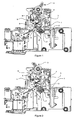
- the figure 1 represents an apparatus according to the invention, and more specifically a neutral pole of a selective circuit breaker, that is to say the opening and closing mechanism placed on a neutral line and conventionally comprising a movable contact (1 ) adapted to cooperate with a fixed contact (2), and an actuator (3) connected to said movable contact (1) via a trigger lock mechanism.
- This mechanism is movable between a locked position of closure and an unlocked position of opening of the line, corresponding to the closing or opening of the contacts (1, 2).
- the operating member (3) allows the control of a change of position of said mechanism, and reflects any unlocking due to the appearance on the line of electrical conditions incompatible with the maintenance of its closure.
- the lock mechanism conventionally comprises a toggle consisting of a link (4) and a connecting rod (5).
- the indentation (7) serves to disengage the spring (10) from the pawl (6), which constitutes a return means enabling the triggering member (8) to be returned to the initial position, allowing the pawl (6) to be immobilized by insertion.
- the trigger member (8) pivots about the axis (9) clockwise, causing the release of the end (11) of the pawl (6), the latter is no longer locked and becomes free to rotate around the axis (13).
- the lock triggers because the link (4) is no longer in stable support against the ramp (12) of the pawl (6) which is no longer locked in rotation.
- the lock is designed to trigger in the event of the sending of an external signal for example by the operator of the electrical network, on a particular control line connected to the neutral module for example via a connector rapid insertion of the conductor in contact with an elastically flexible terminal.
- the lock is triggered by tilting the trigger member (8) about the axis (9) under the action of a rod (14).
- This is connected via a pivoting plate (15) to the plunger core (16) of an electromagnet (17).
- the latter is therefore connected between the control line and the neutral in the module, so that in the event of a neutral break, the electromagnet (17) is no longer powered.
- This configuration provides a positive security of this component by limiting its heating in case of a problem, and therefore the risk that it breaks unexpectedly.
- FIGS. 1 to 3 show that in normal operation of the breaking device of the invention, there is a clearance between the curved end of the rod (14) and said pin (18), allowing an initial idle stroke when the movable core (16) is attracted by the coil of the electromagnet (17), this race being provided to make up the games related to the possible defects of the parts.
- FIGs 4 and 5 show two successive steps of the displacement of the core (16) in the electromagnet (17), and consequently two sequential phases of rotation of the trigger member (8) by the rod (14).
- the triggering member (8) has a uniform end (19) provided to cooperate with a pawl trigger (20), and more particularly with an actuating arm (21) thereof.
- the rod (14) initiates the unlocking of the lock since the trigger member (8) begins its tilting. At this point, the triggering member (8) has no effect on the pawl trigger (20).
- the unciform end (19) of said member (8) is in contact with the actuating arm (21) of the release (20).
- the movable core (16) of the electromagnet (17) ends its stroke within the coil, and the unciform end (19) of the trigger member (8) rotates the trigger (20). ) via the operating arm (21).
- the rotation of the ratchet release (20) drives that of a shaft (22) provided to ensure the mechanical connection with a similar component of a phase pole module associated with the one shown, which concerns only the neutral pole .
- the pawl release (20) is at the end of the stroke, positioning the shaft (22) such that an unlocking of the phase pole (s) associated with the neutral pole shown is produced.
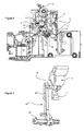
- the shaft (22) is actually part of a transmission part (23) further comprising a lever (24) (see FIG. figures 7 and 8 ) connected via the link (4) of the toggle lever to the control handle (3).
- Said link (4) has in fact an outgrowth (25) maintained in certain phases in contact with the lever (24) and making it possible to modify the positioning of the transmission part (23), and in particular of the shaft (22), depending on the actual joystick position (3).
- the trigger pawl (20) is subject to the shaft (22) with however an angular clearance residual as shown by the representation of the figure 8 .
- the barrel (26) of the pawl release (20) has in fact a protrusion (27) cooperating with a notch (28) of the part (23) and which allows a limited angular displacement corresponding to the sector defined by said notch (28).
- the shaft (26) is rotatably mounted on the shaft (22), on the angular sector delimited by the notch (28).
- a torsion spring (29) whose axially-oriented ends are retained respectively by the operating arm (21) and a rib (30) integral with the lever (24) recalls the pawl trigger (20) in the position shown in FIG. figure 8 , for purposes which will be explained in more detail below.
- the neutral pole electrical apparatus is associated with phase poles so that it has a pre-closure and a post-opening of its contacts (1). , 2). This allows in particular to avoid a possible return of current between two phases. Since the possibility of closing or controlling the opening of the phase poles depends on the angular position of the shaft (22), the kinematics of the entire system leading to the angular displacement of said shaft (22) must be provided to handle said pre-closing and post-opening. Thus, the position taken by the shaft (22) in figure 6 , leading to the opening of the phase poles or poles, occurs before triggering the neutral lock.
- control lever (3) when the control lever (3) is in position such that the contact mobile contact with the fixed contact (2) during a closing phase, and despite the fact that the electromagnet (17) is powered, it is not yet possible to close the contacts of the phase or poles because the handle (3) is not in a stable position of closure, and that the position that it echoes to the shaft (22) through the transmission part (23) does not allow the closure of or phase poles. If there is a remote trip signal when the operator closes the neutral pole, the lock triggers when there is contact between the fixed contact (2) and the moving contact of the neutral pole at the moment when the electromagnet (17) is energized, and the pawl trigger (20) goes into the position prohibiting the closing of the phase pole (s).
Landscapes
- Driving Mechanisms And Operating Circuits Of Arc-Extinguishing High-Tension Switches (AREA)
- Switch Cases, Indication, And Locking (AREA)
Description
La présente invention concerne un appareil électrique de protection multipolaire de tête d'installation avec un module de pôle de neutre destiné à être associé à au moins un module de pôle de phase, et qui comporte un déclencheur à distance intégré, tel que l'appareil décrit dans
Le but est notamment de permettre d'interdire la mise sous tension d'une ligne, à distance, par un signal électrique provenant par exemple du fournisseur d'électricité. L'intérêt d'une telle fonction peut être sécuritaire, lorsqu'un agent des services de distribution de l'électricité doit intervenir sur une ligne, ou purement économique, pour la gestion à distance du fournisseur d'électricité. Le signal est alors dans les deux cas envoyé par l'opérateur du réseau électrique.The purpose is in particular to allow to prohibit the power of a line, remotely, by an electrical signal from, for example, the electricity supplier. The interest of such a function can be safe, when an agent of the services of distribution of electricity must intervene on a line, or purely economic, for the remote management of the electricity supplier. The signal is then in both cases sent by the operator of the electrical network.
L'objectif de la présente invention est d'intégrer cette fonction directement dans le boîtier de l'appareil de protection multipolaire, ce qui implique soit une réorganisation de l'espace intérieur du boîtier, dont la forme extérieure n'est pas modifiée, soit un réaménagement du volume entre les deux dispositifs de connexion de la ligne de pôle de neutre.The objective of the present invention is to integrate this function directly into the housing of the multipole protection device, which implies either a rearrangement of the interior space of the housing, the external shape of which is not modified, either a rearrangement of the volume between the two connecting devices of the neutral pole line.
En d'autres termes, on ajoute une fonction à l'appareil ou au module de pôle de neutre, et les composants nécessaires à la réalisation de ladite fonction doivent dès lors être intégrés dans l'espace disponible. Pour mémoire, un tel pôle comporte à titre principal, entre deux dispositifs de connexion à la ligne, un contact mobile apte à se déplacer entre deux positions respectivement au contact et à distance d'un contact fixe correspondant respectivement à la fermeture et à l'ouverture de la ligne de neutre, et une serrure mécanique placée entre une manette de commande et le contact mobile, au moyen de laquelle les déplacements de la manette sont répercutés au contact mobile et qui assure l'ouverture des contacts en cas de déclenchement provoqué par un organe déclencheur à réception d'un signal d'ouverture véhiculé par une ligne de commande spécifique.In other words, a function is added to the neutral pole apparatus or module, and the components necessary for carrying out said function must therefore be integrated into the available space. For the record, such a pole involves main title, between two line connection devices, a movable contact able to move between two positions respectively in contact and at a distance from a fixed contact respectively corresponding to the closing and opening of the neutral line, and a mechanical lock placed between a control lever and the movable contact, by means of which the movements of the joystick are transmitted to the movable contact and which opens the contacts in the event of triggering caused by a trigger member on receipt of a opening signal conveyed by a specific command line.
Ce déclenchement opéré à distance est possible, selon l'invention, car l'appareil comporte les charactéristiques de la revendication 1, en particulier: :
- un électroaimant dont la bobine est connectée entre un dispositif de connexion de la ligne de commande et le contact mobile, le noyau dudit électroaimant étant apte à entraîner l'organe déclencheur de la serrure à l'encontre d'un ressort de rappel au moyen d'une tringlerie ;
- une pièce de transmission comprenant un levier répercutant le mouvement de la manette à un arbre rotatif orienté parallèlement à l'axe de rotation du contact mobile, ledit arbre pouvant être solidarisé mécaniquement à au moins un appareil ou module de coupure de ligne de phase, sa position angulaire déterminant la fermeture ou l'ouverture du ou des contacts mobiles de chacun de ces appareils ou modules ;
- un déclencheur cliquet interposé entre l'organe déclencheur de la serrure et le contact mobile, comportant un bras de manoeuvre et un levier de maintien dépassant radialement en deux positions angulaires distinctes d'un fût lié en rotation audit arbre, le bras de manoeuvre étant entrainé par l'organe déclencheur de la serrure lorsque ce dernier est sollicité par l'électroaimant et ramenant l'arbre en position correspondant à l'ouverture des lignes de phase avant l'ouverture du contact mobile de neutre, le levier de maintien étant sollicité par le contact mobile de neutre en position d'ouverture de manière à maintenir l'arbre en position d'ouverture de la ou des lignes de phase.
- an electromagnet whose coil is connected between a connection device of the control line and the movable contact, the core of said electromagnet being able to drive the trigger member of the lock against a return spring by means of a linkage;
- a transmission part comprising a lever transmitting the movement of the lever to a rotary shaft oriented parallel to the axis of rotation of the movable contact, said shaft being mechanically attachable to at least one phase line breaking device or module, its angular position determining the closing or opening of the mobile contact or contacts of each of these devices or modules;
- a ratchet release interposed between the trigger member of the lock and the movable contact, comprising an operating arm and a holding lever protruding radially in two distinct angular positions of a shaft connected in rotation with said shaft, the actuating arm being driven by the triggering member of the lock when the latter is urged by the electromagnet and bringing the shaft into position corresponding to the opening of the phase lines before the opening of the moving neutral contact, the holding lever being biased by the moving neutral contact in the open position so as to keep the shaft in the open position of the phase line or lines.
La cinématique de l'ensemble du mécanisme est telle que les contacts de phase ne peuvent pas être refermés avant que ceux de la ligne neutre le soient. A l'inverse, au moment de l'ouverture, le système est prévu pour que le pôle de neutre s'ouvre uniquement lorsque le ou les pôles de phase sont eux-mêmes déjà ouverts.The kinematics of the entire mechanism is such that the phase contacts can not be closed before those of the neutral line are. Conversely, at the time of opening, the system is provided so that the neutral pole opens only when the phase pole or poles are themselves already open.
Le fonctionnement électrique de l'invention est tout à fait normal en l'absence d'un signal externe d'ouverture sur la ligne de commande, susceptible d'alimenter la bobine de l'électroaimant. Lorsqu'un tel signal survient, le ou les pôles de phase s'ouvrent, suivis du pôle de neutre. Il n'est ensuite pas possible de refermer le pôle de neutre si le signal d'interruption est toujours présent : dès que le contact mobile de neutre arrive en pression contre le contact fixe, l'électroaimant est alimenté, et conduit au déverrouillage de la serrure. Même dans l'hypothèse où on maintient la manette de commande du pôle neutre en position de fermeture, les pôles de phase ne peuvent dès lors pas se refermer.The electrical operation of the invention is quite normal in the absence of an external signal opening on the control line, capable of supplying the coil of the electromagnet. When such a signal occurs, the phase poles open, followed by the neutral pole. It is then not possible to close the neutral pole if the interruption signal is still present: as soon as the moving neutral contact comes into pressure against the fixed contact, the electromagnet is energized, and leads to the unlocking of the lock. Even if the control lever of the neutral pole is kept in the closed position, the phase poles can not be closed again.
Un ressort de torsion est interposé entre le fût du déclencheur cliquet et l'arbre de la pièce de transmission, une rotation à l'encontre du ressort et selon un secteur angulaire restreint étant alors autorisée par la liaison mécanique.A torsion spring is interposed between the barrel of the pawl trigger and the shaft of the transmission part, a rotation against the spring and in a restricted angular sector then being authorized by the mechanical link.
En fait, dans la configuration choisie, le noyau mobile de l'électroaimant et l'organe déclencheur sont relié par une tringle libre en rotation à ses deux extrémités de liaison respectivement audit noyau et audit organe déclencheur.In fact, in the chosen configuration, the movable core of the electromagnet and the triggering member are connected by a freely rotating rod to its two connecting ends respectively to said core and said trigger member.
Le mouvement du noyau mobile de l'électroaimant, par exemple dû à son attraction par la bobine, entraine la tringle par traction de son extrémité proximale de l'électroaimant, et ce déplacement a une répercussion au niveau de l'organe déclencheur, à son tour entrainé par l'autre extrémité de la tringle dans le sens d'un déverrouillage de la serrure.The movement of the mobile core of the electromagnet, for example due to its attraction by the coil, causes the rod to pull from its proximal end of the electromagnet, and this displacement has an effect on the triggering member, its tower driven by the other end of the rod in the direction of an unlocking of the lock.
De préférence, la liaison de la tringle à l'organe déclencheur comporte une course à vide initiale, pendant le début du déplacement du noyau mobile de l'électroaimant, conduisant à un déplacement initial de la tringle seule avant entrainement de l'organe déclencheur de la serrure. Cette course à vide sert en particulier à rattraper les jeux liés aux défauts des différentes pièces.Preferably, the connection of the rod to the trigger member comprises an initial vacuum stroke, during the beginning of the displacement of the movable core of the electromagnet, leading to an initial displacement of the rod alone before driving the triggering member of the the lock. This empty race is used in particular to catch the games related to the defects of the different parts.
Plus précisément, la tringle comporte une extrémité recourbée en U guidée par un plot dépassant de l'organe déclencheur de la serrure et s'insérant entre les branches du U. Pour pouvoir mettre en oeuvre la course à vide, le plot en question est placé entre les branches du U à une certaine distance du fond arrondi dudit U lorsque le noyau plongeur de l'électroaimant n'est pas attiré par la bobine.More specifically, the bead wire comprises a curved U end guided by a stud protruding from the trigger member of the lock and inserted between the branches of the U. To be able to implement the idle stroke, the stud in question is placed between the branches of the U at a distance from the rounded bottom of said U when the plunger core of the electromagnet is not attracted by the coil.
Lorsque la course à vide est terminée, la tringle débute l'entrainement de l'organe déclencheur de la serrure, entamant le déverrouillage de cette dernière.When the idle stroke is over, the rod begins the training of the trigger member of the lock, starting unlocking the latter.
Dans un deuxième temps seulement, correspondant de fait à une certaine rotation de l'organe déclencheur, le bras de manoeuvre du déclencheur cliquet est entrainé par l'organe déclencheur. L'organe déclencheur en mouvement exerce des actions concomitantes sur la serrure du pôle de neutre et sur le déclencheur cliquet. La cinématique de l'ensemble du mécanisme fait que la rotation imprimée au déclencheur cliquet par l'organe déclencheur de la serrure - lui-même entrainé par la tringle - positionne en fin de course ledit déclencheur cliquet et par conséquent l'arbre de la pièce de transmission dans une position telle que le ou les pôles de phase s'ouvre(nt) un peu avant le pôle de neutre, et que le contact mobile de neutre peut s'écarter brutalement du contact fixe sous l'effet de moyens de rappel spécifiques et sans que le levier de la pièce de transmission ne fasse obstacle. Le contact mobile ouvert vient alors exercer une pression sur le levier de maintien, sous l'effet desdits moyens de rappel, garantissant la position du déclencheur cliquet et la contrainte de non armement du ou des pôles de phase.In a second step only, corresponding in fact to a certain rotation of the triggering member, the actuating arm of the trigger pawl is driven by the trigger member. The moving trigger member performs concomitant actions on the lock of the neutral pole and the ratchet trigger. The kinematics of the entire mechanism makes the rotation printed trigger trigger by the trigger member of the lock - itself driven by the rod - position at the end of stroke said trigger pawl and therefore the shaft of the coin in a position such that the phase pole (s) opens (s) a little before the neutral pole, and that the moving neutral contact can deviate abruptly from the fixed contact under the effect of biasing means specific and without the lever of the transmission part obstructing. The open mobile contact then exerts pressure on the holding lever, under the effect of said biasing means, ensuring the position of the pawl trigger and the non-arming stress of the phase pole or poles.
En fait, plus précisément, l'organe déclencheur est relié au boîtier de l'appareil par une liaison rotative, et présente une extrémité unciforme configurée pour entrainer le bras de manoeuvre lors de son trajet rotatif. Le positionnement relatif et la configuration précise donnés aux différentes pièces (extrémité unciforme, bras de manoeuvre, ...) sont tels qu'ils permettent la succession des séquences prédéterminées telles que décrites auparavant.In fact, more specifically, the triggering member is connected to the housing of the apparatus by a rotary connection, and has a shaped end configured to drive the operating arm during its rotary path. The relative positioning and the precise configuration given to the various parts (end unciform, operating arm, ...) are such that they allow the succession of predetermined sequences as previously described.
Dans l'invention, le levier de la pièce de transmission est entrainé par un maillon de la serrure dont une extrémité pivote dans la manette et l'autre extrémité est liée à rotation avec l'extrémité d'une biellette avec laquelle elle forme une genouillère, l'extrémité opposée de ladite biellette étant reliée libre en rotation avec le contact mobile.In the invention, the lever of the transmission part is driven by a link of the lock, one end of which pivots in the handle and the other end is rotatably connected to the end of a link with which it forms a knee joint, the opposite end of said link being freely connected in rotation with the movable contact.
Il s'agit d'un mécanisme traditionnel de liaison d'une manette de commande avec un contact mobile, répercutant la position de l'une à l'autre et vice versa. La genouillère permet la mise en appui du contact mobile sur le contact fixe, à l'aide d'un système utilisant arc-boutement et frottement en association avec un dispositif de déclenchement.This is a traditional mechanism of connecting a joystick with a moving contact, echoing the position of one to the other and vice versa. The toggle lever allows the mobile contact to bear on the fixed contact, using a system using buttressing and friction in combination with a triggering device.
Le maillon de la genouillère se déplace au contact d'un cliquet pivotant dont l'une des extrémités forme une rampe de guidage pour le maillon et l'autre extrémité s'insère dans une encoche de l'organe déclencheur de la serrure. Lorsque ce dernier est entrainé par la tringle, il libère une extrémité du cliquet qui pivote sous l'effet de la contrainte exercée à son extrémité opposée par le maillon, et la genouillère change d'état mécanique, faisant déclencher la serrure sous l'effet des moyens de rappel du contact mobile en position d'ouverture.The link of the knee lever moves in contact with a pivoting ratchet, one end of which forms a guide ramp for the link and the other end is inserted into a notch of the trigger member of the lock. When the latter is driven by the rod, it releases one end of the ratchet which pivots under the effect of the stress exerted at its opposite end by the link, and the toggle switch changes mechanical state, causing the lock to trigger under the effect return means of the movable contact in the open position.
L'invention va à présent être décrite plus en détail, en référence aux figures annexées, pour lesquelles :
- la
figure 1 est une vue en élévation de face d'un pôle de neutre d'un appareil de protection de ligne muni d'un mécanisme de serrure selon l'invention, dans une position dans laquelle les contacts respectivement mobile et fixe sont en position d'ouverture, à distance l'un de l'autre ; - la
figure 2 montre un détail agrandi de la serrure de lafigure 1 ; - la
figure 3 représente le même appareil qu'enfigure 1 , contacts fermés; - les
figures 4 à 6 montrent les différentes phases de déclenchement de la serrure provoquées par un signal externe de déclenchement ; - la
figure 7 illustre le lien mécanique qui existe entre la manette de commande et le déclencheur à cliquet, via une pièce de transmission dotée d'un levier et le maillon de la serrure de déclenchement ; - la
figure 8 représente un agrandissement de la liaison mécanique entre le déclencheur à cliquets d'une part et la pièce de transmission du mouvement de la manette d'autre part.
- the
figure 1 is a front elevational view of a neutral pole of a line protection device provided with a lock mechanism according to the invention, in a position in which the respectively movable and fixed contacts are in the open position at a distance from each other; - the
figure 2 shows an enlarged detail of the lock of thefigure 1 ; - the
figure 3 represents the same device asfigure 1 , closed contacts; - the
Figures 4 to 6 show the different phases of triggering of the lock caused by an external trigger signal; - the
figure 7 illustrates the mechanical link that exists between the control handle and the ratchet release, via a transmission piece with a lever and the link of the trigger lock; - the
figure 8 represents an enlargement of the mechanical connection between the pawl trigger on the one hand and the transmission part of the movement of the lever on the other hand.
La
L'échancrure (7) sert de dégagement au ressort (10) du cliquet (6), qui constitue un moyen de rappel permettant de ramener l'organe déclencheur (8) en position initiale autorisant l'immobilisation du cliquet (6) par insertion de son extrémité (11) dans une encoche du déclencheur, et par conséquent le guidage ferme du maillon (4) le long de la rampe (12) constituée à son autre extrémité en vue de permettre la transmission par la genouillère du déplacement de l'organe de manoeuvre (3) dans le sens de la fermeture des contacts (1 , 2). Lorsque l'organe déclencheur (8) pivote autour de l'axe (9) dans le sens horaire, entrainant la libération de l'extrémité (11) du cliquet (6), ce dernier n'est plus bloqué et devient libre en rotation autour de l'axe (13). Dans ce cas, la serrure déclenche car le maillon (4) n'est plus en appui stable contre la rampe (12) du cliquet (6) qui n'est plus bloqué en rotation.The indentation (7) serves to disengage the spring (10) from the pawl (6), which constitutes a return means enabling the triggering member (8) to be returned to the initial position, allowing the pawl (6) to be immobilized by insertion. its end (11) in a notch of the trigger, and therefore the firm guidance of the link (4) along the ramp (12) formed at its other end to allow the transmission by the toggle of the displacement of the operating member (3) in the direction of closing the contacts (1, 2). When the trigger member (8) pivots about the axis (9) clockwise, causing the release of the end (11) of the pawl (6), the latter is no longer locked and becomes free to rotate around the axis (13). In this case, the lock triggers because the link (4) is no longer in stable support against the ramp (12) of the pawl (6) which is no longer locked in rotation.
Selon l'invention, la serrure est prévue pour déclencher dans l'hypothèse de l'envoi d'un signal extérieur par exemple par l'opérateur du réseau électrique, sur une ligne de commande particulière connectée au module de neutre par exemple via un connecteur à enfichage rapide du conducteur au contact d'une borne flexible élastiquement. Le déclenchement de la serrure s'effectue par basculement de l'organe déclencheur (8) autour de l'axe (9) sous l'action d'une tringle (14). Celle-ci est reliée, via une platine pivotante (15), au noyau plongeur (16) d'un électroaimant (17). Ce dernier est donc connecté entre la ligne de commande et le neutre dans le module, ce qui fait qu'en cas de rupture de neutre, l'électroaimant (17) n'est plus alimenté. Cette configuration procure une sécurité positive de ce composant en limitant son échauffement en cas de problème, et donc le risque qu'il casse intempestivement.According to the invention, the lock is designed to trigger in the event of the sending of an external signal for example by the operator of the electrical network, on a particular control line connected to the neutral module for example via a connector rapid insertion of the conductor in contact with an elastically flexible terminal. The lock is triggered by tilting the trigger member (8) about the axis (9) under the action of a rod (14). This is connected via a pivoting plate (15) to the plunger core (16) of an electromagnet (17). The latter is therefore connected between the control line and the neutral in the module, so that in the event of a neutral break, the electromagnet (17) is no longer powered. This configuration provides a positive security of this component by limiting its heating in case of a problem, and therefore the risk that it breaks unexpectedly.
En l'absence d'un signal de déclenchement à distance, aucune action n'est exercée par la tringle (14) sur l'organe déclencheur (8), et le fonctionnement du pôle de neutre de l'appareil de coupure est tel que figurant dans les
Si un signal de déclenchement est envoyé en cours de fonctionnement, c'est à dire lorsque les contacts (1, 2) sont fermés, excitant la bobine de l'électroaimant (17), le noyau magnétique (16) est attiré à l'intérieur de ladite bobine (17) comme cela est montré en
Lorsque ledit jeu est comblé, comme cela apparaît en
En
Dans la position dudit arbre représentée en
L'arbre (22) fait en réalité partie d'une pièce de transmission (23) comprenant par ailleurs un levier (24) (voir en
Pour des raisons de sécurité, l'appareil électrique à pôle de neutre selon l'invention est associé à des pôles de phase de telle sorte qu'il bénéficie d'une pré-fermeture et d'une post-ouverture de ses contacts (1,2). Cela permet notamment d'éviter un éventuel retour de courant entre deux phases. Etant donné que la possibilité de fermeture ou la commande de l'ouverture des pôles de phase dépend de la position angulaire de l'arbre (22), la cinématique de l'ensemble du système conduisant au déplacement angulaire dudit arbre (22) doit être prévu de manière à gérer lesdites pré-fermeture et post-ouverture. Ainsi, la position prise par l'arbre (22) en
A l'inverse, en revenant à la
Même dans l'hypothèse où l'utilisateur force artificiellement la manette (3) en position théorique de fermeture des contacts (1, 2), l'existence d'un signal à distance d'ouverture de la ligne doit conduire à l'impossibilité de fermer les pôles de phase. C'est bien le cas, puisque la serrure ayant déclenché, le contact mobile (1) repousse le déclencheur cliquet (20) et par conséquent l'arbre (22) en position d'ouverture des contacts du ou des pôles de phase par appui du contact mobile (1) ouvert sur le levier de maintien (31), et que les moyens de rappel en position d'ouverture du contact mobile (1) exercent par le biais de ce dernier une contrainte dans cette position.Even if the user artificially forces the lever (3) in the theoretical closing position of the contacts (1, 2), the existence of a signal at a distance from the opening of the line must lead to the impossibility to close the phase poles. This is the case, since the lock having triggered, the movable contact (1) pushes the trigger pawl (20) and therefore the shaft (22) in the open position of the contacts of the phase or poles by pressing the movable contact (1) open on the holding lever (31), and that the return means in the open position of the movable contact (1) exert through the latter a constraint in this position.
La configuration montrée en référence aux figures n'est qu'un exemple possible, nullement limitatif, de l'invention.The configuration shown with reference to the figures is only one possible example, not limiting, of the invention.
Claims (8)
- A multipolar protective electrical appliance with a neutral pole module associated with at least one phase line cut-off module, including two devices for connection to the neutral line, a mobile contact (1) capable of moving between two positions respectively in contact with and away from a fixed contact (2) respectively corresponding to the closing and to the opening of the neutral line, a mechanical lock placed between a control handle (3) and the mobile contact (1), by means of which the displacements of the handle (3) are passed on to the mobile contact (1) and which ensures the opening of the contacts (1, 2) in the case of a trigger caused by a triggering member (8) upon receiving an opening signal conveyed by a control line, characterized in that it includes:- an electromagnet (17), the coil of which is connected between a device for connecting the control line and the mobile contact (1), the core (16) of said electromagnet (17) being able to drive the triggering member (8) of the lock against a return spring (10) by means of a linkage (14);- a transmission part (23) comprising a lever (24) passing on the movement of the handle (3) to a rotary shaft (22) oriented parallel to the axis of rotation of the mobile contact (1), said shaft (22) may be mechanically secured to at least one phase line cut-off appliance or module, its angular position determining the closing or the opening of the mobile contact(s) of each of these appliances or modules;- a pawl-type'triggering unit (20) interposed between the triggering member (8) of the lock and the mobile contact (1), including a maneuvering arm (21) and a holding lever (31), radially jutting out into distinct angular positions of a barrel (26), rotationally bound to said shaft (22), the maneuvering arm (21) being driven by the triggering member (8) of the lock when the latter is actuated by the electromagnet (17) and bringing back the shaft (22), into a position corresponding to the opening of the phase lines before opening the neutral mobile contact (1), the holding lever (31) being urged by the neutral mobile contact (1), into the opening position so as to maintain the shaft (22) in the position for opening the phase line(s).
- The electric appliance according to the preceding claim, characterized in that a torsional spring (29) is interposed between the barrel (26) of the pawl-type triggering unit (20) and the shaft (22), rotation along a limited angular sector being allowed by their connection.
- The electric appliance according to one of the preceding claims, characterized in that the mobile core (16) of the electromagnet (17) and the triggering member (8) are connected by a linkage rod (14) free to rotate at its two ends for connecting to said core (16) and to said triggering member (8), respectively.
- The electric appliance according to the preceding claim, characterized in that the connection of the linkage rod (14) to the triggering member (8) includes an initial free travel during the beginning of the displacement of the mobile core (16) of the electromagnet (17), leading to an initial displacement of the linkage rod (14) alone before driving the triggering member (8) of the lock.
- The electric appliance according to the preceding claim, characterized in that the linkage rod (14) includes a U-curved end guided by a stud (18) jutting out from the triggering member (8) of the lock and being inserted between the branches of the U.
- The electric appliance according to one of the preceding claims, characterized in that the triggering member (8) is connected to the casing through a rotary connection, and has a hook-shaped end (19) configured in order to drive the maneuvering arm (21) during its rotary path.
- The electric appliance according to one of the preceding claims, characterized in that the lever (24) of the transmission part (23) is driven by a link (4) of the lock, one end of which pivots in the handle (3) and the other end is rotationally bound to the end of a connecting rod (5) with which it forms a knuckle joint, the opposite end of said connecting rod (5) being connected with the mobile contact (1) so as to freely rotate.
- The electric appliance according to the preceding claim, characterized in that the link (4) of the knuckle joint moves into contact with a pivoting pawl (6), one of the ends (12) of which forms a guiding ramp for the link (4) and the other end (11) is inserted into a notch of the triggering member (8) of the lock.
Applications Claiming Priority (1)
| Application Number | Priority Date | Filing Date | Title |
|---|---|---|---|
| FR0955295A FR2948814B1 (en) | 2009-07-29 | 2009-07-29 | MULTIPOLAR PROTECTION ELECTRICAL APPARATUS WITH REMOTE TRIGGERING. |
Publications (2)
| Publication Number | Publication Date |
|---|---|
| EP2280406A1 EP2280406A1 (en) | 2011-02-02 |
| EP2280406B1 true EP2280406B1 (en) | 2012-07-18 |
Family
ID=41506394
Family Applications (1)
| Application Number | Title | Priority Date | Filing Date |
|---|---|---|---|
| EP20100305830 Not-in-force EP2280406B1 (en) | 2009-07-29 | 2010-07-27 | Electrical appliance for multipolar protection with remote triggering. |
Country Status (2)
| Country | Link |
|---|---|
| EP (1) | EP2280406B1 (en) |
| FR (1) | FR2948814B1 (en) |
Family Cites Families (5)
| Publication number | Priority date | Publication date | Assignee | Title |
|---|---|---|---|---|
| JPS58131636A (en) * | 1982-01-29 | 1983-08-05 | 松下電工株式会社 | Remote control type circuit breaker |
| JPS61230214A (en) * | 1985-04-04 | 1986-10-14 | 三菱電機株式会社 | Circuit breaker |
| FR2640423B1 (en) * | 1988-12-14 | 1991-10-04 | Merlin Gerin | CONTROL MECHANISM OF A MULTIPOLAR DIFFERENTIAL SWITCH WITH ROTATING SWITCHING BAR |
| DE4118377C2 (en) * | 1991-06-05 | 1999-03-04 | Hager Electro Gmbh | Line and / or device circuit breaker |
| FR2788373B1 (en) * | 1999-01-08 | 2001-02-16 | Cahors App Elec | CIRCUIT BREAKER / DISCONNECTOR WITH LOCKED POSITION |
-
2009
- 2009-07-29 FR FR0955295A patent/FR2948814B1/en not_active Expired - Fee Related
-
2010
- 2010-07-27 EP EP20100305830 patent/EP2280406B1/en not_active Not-in-force
Also Published As
| Publication number | Publication date |
|---|---|
| FR2948814B1 (en) | 2011-07-22 |
| FR2948814A1 (en) | 2011-02-04 |
| EP2280406A1 (en) | 2011-02-02 |
Similar Documents
| Publication | Publication Date | Title |
|---|---|---|
| EP0295155B1 (en) | Modular breaker with an auxiliary tripping block associated with a multipole breaker block | |
| EP0224396A1 (en) | Control mechanism for a low-tension electric circuit breaker | |
| EP0058585B1 (en) | Operating mechanism for electrical switching apparatuses with three separate positions | |
| FR2581791A1 (en) | INJURIOUS MANUAL CLOSURE MECHANISM OF CURRENT CUTTING APPARATUS | |
| EP2368256B1 (en) | Mechanical trip device for a line switchgear | |
| FR2900498A1 (en) | CIRCUIT BREAKER | |
| EP0338930A1 (en) | Circuit breakers or differential circuit breakers | |
| EP0326446B1 (en) | Auxiliary controlling and indicating switch for a modular multipole circuit breaker | |
| BE1000208A6 (en) | Drive device for the engagement and remote activation of an automatic switch. | |
| EP0161946A1 (en) | Auxiliary module for connection to a circuit breaker | |
| EP1965405B1 (en) | Offset activation device for a circuit breaker including a trigger assistance device | |
| EP2377139B1 (en) | Remote control device and circuit breaker with such device | |
| FR2817078A1 (en) | Circuit breaker/differential circuit breaker modular protection apparatus remote command unit having driver reengaging apparatus and second driver switching apparatus electronic circuit controlled. | |
| EP2717284B1 (en) | Operating device of an electric protection apparatus and electric protection apparatus comprising same | |
| EP2280406B1 (en) | Electrical appliance for multipolar protection with remote triggering. | |
| EP1274109B1 (en) | Circuit breaker and it's opperating mechanism | |
| CH666766A5 (en) | CIRCUIT BREAKER WITH REMOTE CONTROL REMOTE CONTROL AT A POINT CENTER ON THE MOVEMENT AXIS OF THE REMOTE CONTROL SOLENOID. | |
| FR2959594A1 (en) | Remote control device for use with cutting device to control remote-controlled circuit breaker, has braking units acting on shaft to break lever when lever is moved toward closing position of mobile and fixed contacts | |
| EP2642502B1 (en) | Trip unit for an electric protection apparatus and electric protection apparatus comprising one such unit | |
| FR2940515A1 (en) | Remote control device for controlling remote-controlled circuit breaker in electrical installation, has driving unit whose mechanism comprises elements displaced in translation along driving axis and displaced in rotation around axis | |
| EP3232459B1 (en) | Electric line protection apparatus | |
| FR2940517A1 (en) | Remote control device for remote-controlled circuit breaker, has detection units to detect position of remote control shaft rotationally mounted around remote control axis, where shaft actuates electrical contacts of interruption device | |
| FR3057389A1 (en) | DIFFERENTIAL ELECTRICAL CUTTING APPARATUS HAVING DIFFERENTIAL FUNCTION TEST DEVICE | |
| FR2892849A1 (en) | Fixed and movable contacts locking mechanism for e.g. circuit breaker, has movable contact rigidly fixed to contact holder, and compression spring placed between flange and fixed contact | |
| FR2796488A1 (en) | DEVICE FOR ACTIVATING AND DEACTIVATING SWITCHING APPARATUSES IN BLOCK FORM |
Legal Events
| Date | Code | Title | Description |
|---|---|---|---|
| PUAI | Public reference made under article 153(3) epc to a published international application that has entered the european phase |
Free format text: ORIGINAL CODE: 0009012 |
|
| AK | Designated contracting states |
Kind code of ref document: A1 Designated state(s): AL AT BE BG CH CY CZ DE DK EE ES FI FR GB GR HR HU IE IS IT LI LT LU LV MC MK MT NL NO PL PT RO SE SI SK SM TR |
|
| AX | Request for extension of the european patent |
Extension state: BA ME RS |
|
| 17P | Request for examination filed |
Effective date: 20110328 |
|
| RIC1 | Information provided on ipc code assigned before grant |
Ipc: H01H 71/10 20060101AFI20110718BHEP |
|
| GRAP | Despatch of communication of intention to grant a patent |
Free format text: ORIGINAL CODE: EPIDOSNIGR1 |
|
| GRAC | Information related to communication of intention to grant a patent modified |
Free format text: ORIGINAL CODE: EPIDOSCIGR1 |
|
| GRAS | Grant fee paid |
Free format text: ORIGINAL CODE: EPIDOSNIGR3 |
|
| GRAA | (expected) grant |
Free format text: ORIGINAL CODE: 0009210 |
|
| AK | Designated contracting states |
Kind code of ref document: B1 Designated state(s): AL AT BE BG CH CY CZ DE DK EE ES FI FR GB GR HR HU IE IS IT LI LT LU LV MC MK MT NL NO PL PT RO SE SI SK SM TR |
|
| REG | Reference to a national code |
Ref country code: GB Ref legal event code: FG4D Free format text: NOT ENGLISH |
|
| REG | Reference to a national code |
Ref country code: CH Ref legal event code: EP |
|
| REG | Reference to a national code |
Ref country code: AT Ref legal event code: REF Ref document number: 567201 Country of ref document: AT Kind code of ref document: T Effective date: 20120815 Ref country code: IE Ref legal event code: FG4D Free format text: LANGUAGE OF EP DOCUMENT: FRENCH |
|
| REG | Reference to a national code |
Ref country code: DE Ref legal event code: R096 Ref document number: 602010002240 Country of ref document: DE Effective date: 20120913 |
|
| REG | Reference to a national code |
Ref country code: NL Ref legal event code: VDEP Effective date: 20120718 |
|
| REG | Reference to a national code |
Ref country code: AT Ref legal event code: MK05 Ref document number: 567201 Country of ref document: AT Kind code of ref document: T Effective date: 20120718 |
|
| REG | Reference to a national code |
Ref country code: LT Ref legal event code: MG4D Effective date: 20120718 |
|
| BERE | Be: lapsed |
Owner name: HAGER ELECTRO SAS Effective date: 20120731 |
|
| PG25 | Lapsed in a contracting state [announced via postgrant information from national office to epo] |
Ref country code: CY Free format text: LAPSE BECAUSE OF FAILURE TO SUBMIT A TRANSLATION OF THE DESCRIPTION OR TO PAY THE FEE WITHIN THE PRESCRIBED TIME-LIMIT Effective date: 20120718 Ref country code: HR Free format text: LAPSE BECAUSE OF FAILURE TO SUBMIT A TRANSLATION OF THE DESCRIPTION OR TO PAY THE FEE WITHIN THE PRESCRIBED TIME-LIMIT Effective date: 20120718 Ref country code: IS Free format text: LAPSE BECAUSE OF FAILURE TO SUBMIT A TRANSLATION OF THE DESCRIPTION OR TO PAY THE FEE WITHIN THE PRESCRIBED TIME-LIMIT Effective date: 20121118 Ref country code: LT Free format text: LAPSE BECAUSE OF FAILURE TO SUBMIT A TRANSLATION OF THE DESCRIPTION OR TO PAY THE FEE WITHIN THE PRESCRIBED TIME-LIMIT Effective date: 20120718 Ref country code: NO Free format text: LAPSE BECAUSE OF FAILURE TO SUBMIT A TRANSLATION OF THE DESCRIPTION OR TO PAY THE FEE WITHIN THE PRESCRIBED TIME-LIMIT Effective date: 20121018 Ref country code: AT Free format text: LAPSE BECAUSE OF FAILURE TO SUBMIT A TRANSLATION OF THE DESCRIPTION OR TO PAY THE FEE WITHIN THE PRESCRIBED TIME-LIMIT Effective date: 20120718 Ref country code: FI Free format text: LAPSE BECAUSE OF FAILURE TO SUBMIT A TRANSLATION OF THE DESCRIPTION OR TO PAY THE FEE WITHIN THE PRESCRIBED TIME-LIMIT Effective date: 20120718 |
|
| PG25 | Lapsed in a contracting state [announced via postgrant information from national office to epo] |
Ref country code: PL Free format text: LAPSE BECAUSE OF FAILURE TO SUBMIT A TRANSLATION OF THE DESCRIPTION OR TO PAY THE FEE WITHIN THE PRESCRIBED TIME-LIMIT Effective date: 20120718 Ref country code: LV Free format text: LAPSE BECAUSE OF FAILURE TO SUBMIT A TRANSLATION OF THE DESCRIPTION OR TO PAY THE FEE WITHIN THE PRESCRIBED TIME-LIMIT Effective date: 20120718 Ref country code: GR Free format text: LAPSE BECAUSE OF FAILURE TO SUBMIT A TRANSLATION OF THE DESCRIPTION OR TO PAY THE FEE WITHIN THE PRESCRIBED TIME-LIMIT Effective date: 20121019 Ref country code: SI Free format text: LAPSE BECAUSE OF FAILURE TO SUBMIT A TRANSLATION OF THE DESCRIPTION OR TO PAY THE FEE WITHIN THE PRESCRIBED TIME-LIMIT Effective date: 20120718 Ref country code: MC Free format text: LAPSE BECAUSE OF NON-PAYMENT OF DUE FEES Effective date: 20120731 Ref country code: PT Free format text: LAPSE BECAUSE OF FAILURE TO SUBMIT A TRANSLATION OF THE DESCRIPTION OR TO PAY THE FEE WITHIN THE PRESCRIBED TIME-LIMIT Effective date: 20121119 Ref country code: SE Free format text: LAPSE BECAUSE OF FAILURE TO SUBMIT A TRANSLATION OF THE DESCRIPTION OR TO PAY THE FEE WITHIN THE PRESCRIBED TIME-LIMIT Effective date: 20120718 Ref country code: MK Free format text: LAPSE BECAUSE OF FAILURE TO SUBMIT A TRANSLATION OF THE DESCRIPTION OR TO PAY THE FEE WITHIN THE PRESCRIBED TIME-LIMIT Effective date: 20120718 |
|
| PG25 | Lapsed in a contracting state [announced via postgrant information from national office to epo] |
Ref country code: NL Free format text: LAPSE BECAUSE OF FAILURE TO SUBMIT A TRANSLATION OF THE DESCRIPTION OR TO PAY THE FEE WITHIN THE PRESCRIBED TIME-LIMIT Effective date: 20120718 |
|
| PG25 | Lapsed in a contracting state [announced via postgrant information from national office to epo] |
Ref country code: EE Free format text: LAPSE BECAUSE OF FAILURE TO SUBMIT A TRANSLATION OF THE DESCRIPTION OR TO PAY THE FEE WITHIN THE PRESCRIBED TIME-LIMIT Effective date: 20120718 Ref country code: ES Free format text: LAPSE BECAUSE OF FAILURE TO SUBMIT A TRANSLATION OF THE DESCRIPTION OR TO PAY THE FEE WITHIN THE PRESCRIBED TIME-LIMIT Effective date: 20121029 Ref country code: RO Free format text: LAPSE BECAUSE OF FAILURE TO SUBMIT A TRANSLATION OF THE DESCRIPTION OR TO PAY THE FEE WITHIN THE PRESCRIBED TIME-LIMIT Effective date: 20120718 Ref country code: CZ Free format text: LAPSE BECAUSE OF FAILURE TO SUBMIT A TRANSLATION OF THE DESCRIPTION OR TO PAY THE FEE WITHIN THE PRESCRIBED TIME-LIMIT Effective date: 20120718 Ref country code: DK Free format text: LAPSE BECAUSE OF FAILURE TO SUBMIT A TRANSLATION OF THE DESCRIPTION OR TO PAY THE FEE WITHIN THE PRESCRIBED TIME-LIMIT Effective date: 20120718 |
|
| REG | Reference to a national code |
Ref country code: IE Ref legal event code: MM4A |
|
| PLBE | No opposition filed within time limit |
Free format text: ORIGINAL CODE: 0009261 |
|
| STAA | Information on the status of an ep patent application or granted ep patent |
Free format text: STATUS: NO OPPOSITION FILED WITHIN TIME LIMIT |
|
| PG25 | Lapsed in a contracting state [announced via postgrant information from national office to epo] |
Ref country code: BE Free format text: LAPSE BECAUSE OF NON-PAYMENT OF DUE FEES Effective date: 20120731 Ref country code: IT Free format text: LAPSE BECAUSE OF FAILURE TO SUBMIT A TRANSLATION OF THE DESCRIPTION OR TO PAY THE FEE WITHIN THE PRESCRIBED TIME-LIMIT Effective date: 20120718 Ref country code: SK Free format text: LAPSE BECAUSE OF FAILURE TO SUBMIT A TRANSLATION OF THE DESCRIPTION OR TO PAY THE FEE WITHIN THE PRESCRIBED TIME-LIMIT Effective date: 20120718 |
|
| REG | Reference to a national code |
Ref country code: FR Ref legal event code: ST Effective date: 20130426 |
|
| 26N | No opposition filed |
Effective date: 20130419 |
|
| PG25 | Lapsed in a contracting state [announced via postgrant information from national office to epo] |
Ref country code: MT Free format text: LAPSE BECAUSE OF FAILURE TO SUBMIT A TRANSLATION OF THE DESCRIPTION OR TO PAY THE FEE WITHIN THE PRESCRIBED TIME-LIMIT Effective date: 20120718 Ref country code: BG Free format text: LAPSE BECAUSE OF FAILURE TO SUBMIT A TRANSLATION OF THE DESCRIPTION OR TO PAY THE FEE WITHIN THE PRESCRIBED TIME-LIMIT Effective date: 20121018 Ref country code: IE Free format text: LAPSE BECAUSE OF NON-PAYMENT OF DUE FEES Effective date: 20120727 |
|
| REG | Reference to a national code |
Ref country code: DE Ref legal event code: R097 Ref document number: 602010002240 Country of ref document: DE Effective date: 20130419 |
|
| PG25 | Lapsed in a contracting state [announced via postgrant information from national office to epo] |
Ref country code: FR Free format text: LAPSE BECAUSE OF NON-PAYMENT OF DUE FEES Effective date: 20120918 |
|
| PG25 | Lapsed in a contracting state [announced via postgrant information from national office to epo] |
Ref country code: AL Free format text: LAPSE BECAUSE OF FAILURE TO SUBMIT A TRANSLATION OF THE DESCRIPTION OR TO PAY THE FEE WITHIN THE PRESCRIBED TIME-LIMIT Effective date: 20120718 |
|
| PG25 | Lapsed in a contracting state [announced via postgrant information from national office to epo] |
Ref country code: TR Free format text: LAPSE BECAUSE OF FAILURE TO SUBMIT A TRANSLATION OF THE DESCRIPTION OR TO PAY THE FEE WITHIN THE PRESCRIBED TIME-LIMIT Effective date: 20120718 |
|
| PG25 | Lapsed in a contracting state [announced via postgrant information from national office to epo] |
Ref country code: LU Free format text: LAPSE BECAUSE OF NON-PAYMENT OF DUE FEES Effective date: 20120727 Ref country code: SM Free format text: LAPSE BECAUSE OF FAILURE TO SUBMIT A TRANSLATION OF THE DESCRIPTION OR TO PAY THE FEE WITHIN THE PRESCRIBED TIME-LIMIT Effective date: 20120718 |
|
| PG25 | Lapsed in a contracting state [announced via postgrant information from national office to epo] |
Ref country code: HU Free format text: LAPSE BECAUSE OF FAILURE TO SUBMIT A TRANSLATION OF THE DESCRIPTION OR TO PAY THE FEE WITHIN THE PRESCRIBED TIME-LIMIT Effective date: 20100727 |
|
| REG | Reference to a national code |
Ref country code: CH Ref legal event code: PL |
|
| GBPC | Gb: european patent ceased through non-payment of renewal fee |
Effective date: 20140727 |
|
| PG25 | Lapsed in a contracting state [announced via postgrant information from national office to epo] |
Ref country code: CH Free format text: LAPSE BECAUSE OF NON-PAYMENT OF DUE FEES Effective date: 20140731 Ref country code: LI Free format text: LAPSE BECAUSE OF NON-PAYMENT OF DUE FEES Effective date: 20140731 |
|
| PG25 | Lapsed in a contracting state [announced via postgrant information from national office to epo] |
Ref country code: GB Free format text: LAPSE BECAUSE OF NON-PAYMENT OF DUE FEES Effective date: 20140727 |
|
| PGFP | Annual fee paid to national office [announced via postgrant information from national office to epo] |
Ref country code: DE Payment date: 20220727 Year of fee payment: 13 |
|
| REG | Reference to a national code |
Ref country code: DE Ref legal event code: R119 Ref document number: 602010002240 Country of ref document: DE |
|
| PG25 | Lapsed in a contracting state [announced via postgrant information from national office to epo] |
Ref country code: DE Free format text: LAPSE BECAUSE OF NON-PAYMENT OF DUE FEES Effective date: 20240201 |