EP2280152A1 - Waste heat recovering device - Google Patents
Waste heat recovering device Download PDFInfo
- Publication number
- EP2280152A1 EP2280152A1 EP09724074A EP09724074A EP2280152A1 EP 2280152 A1 EP2280152 A1 EP 2280152A1 EP 09724074 A EP09724074 A EP 09724074A EP 09724074 A EP09724074 A EP 09724074A EP 2280152 A1 EP2280152 A1 EP 2280152A1
- Authority
- EP
- European Patent Office
- Prior art keywords
- working fluid
- low
- temperature
- heat exchanger
- temperature heat
- Prior art date
- Legal status (The legal status is an assumption and is not a legal conclusion. Google has not performed a legal analysis and makes no representation as to the accuracy of the status listed.)
- Withdrawn
Links
Images


Classifications
-
- F—MECHANICAL ENGINEERING; LIGHTING; HEATING; WEAPONS; BLASTING
- F02—COMBUSTION ENGINES; HOT-GAS OR COMBUSTION-PRODUCT ENGINE PLANTS
- F02G—HOT GAS OR COMBUSTION-PRODUCT POSITIVE-DISPLACEMENT ENGINE PLANTS; USE OF WASTE HEAT OF COMBUSTION ENGINES; NOT OTHERWISE PROVIDED FOR
- F02G5/00—Profiting from waste heat of combustion engines, not otherwise provided for
- F02G5/02—Profiting from waste heat of exhaust gases
- F02G5/04—Profiting from waste heat of exhaust gases in combination with other waste heat from combustion engines
-
- F—MECHANICAL ENGINEERING; LIGHTING; HEATING; WEAPONS; BLASTING
- F01—MACHINES OR ENGINES IN GENERAL; ENGINE PLANTS IN GENERAL; STEAM ENGINES
- F01K—STEAM ENGINE PLANTS; STEAM ACCUMULATORS; ENGINE PLANTS NOT OTHERWISE PROVIDED FOR; ENGINES USING SPECIAL WORKING FLUIDS OR CYCLES
- F01K23/00—Plants characterised by more than one engine delivering power external to the plant, the engines being driven by different fluids
- F01K23/02—Plants characterised by more than one engine delivering power external to the plant, the engines being driven by different fluids the engine cycles being thermally coupled
- F01K23/06—Plants characterised by more than one engine delivering power external to the plant, the engines being driven by different fluids the engine cycles being thermally coupled combustion heat from one cycle heating the fluid in another cycle
- F01K23/065—Plants characterised by more than one engine delivering power external to the plant, the engines being driven by different fluids the engine cycles being thermally coupled combustion heat from one cycle heating the fluid in another cycle the combustion taking place in an internal combustion piston engine, e.g. a diesel engine
-
- F—MECHANICAL ENGINEERING; LIGHTING; HEATING; WEAPONS; BLASTING
- F01—MACHINES OR ENGINES IN GENERAL; ENGINE PLANTS IN GENERAL; STEAM ENGINES
- F01N—GAS-FLOW SILENCERS OR EXHAUST APPARATUS FOR MACHINES OR ENGINES IN GENERAL; GAS-FLOW SILENCERS OR EXHAUST APPARATUS FOR INTERNAL-COMBUSTION ENGINES
- F01N5/00—Exhaust or silencing apparatus combined or associated with devices profiting by exhaust energy
- F01N5/02—Exhaust or silencing apparatus combined or associated with devices profiting by exhaust energy the devices using heat
-
- F—MECHANICAL ENGINEERING; LIGHTING; HEATING; WEAPONS; BLASTING
- F01—MACHINES OR ENGINES IN GENERAL; ENGINE PLANTS IN GENERAL; STEAM ENGINES
- F01N—GAS-FLOW SILENCERS OR EXHAUST APPARATUS FOR MACHINES OR ENGINES IN GENERAL; GAS-FLOW SILENCERS OR EXHAUST APPARATUS FOR INTERNAL-COMBUSTION ENGINES
- F01N2240/00—Combination or association of two or more different exhaust treating devices, or of at least one such device with an auxiliary device, not covered by indexing codes F01N2230/00 or F01N2250/00, one of the devices being
- F01N2240/02—Combination or association of two or more different exhaust treating devices, or of at least one such device with an auxiliary device, not covered by indexing codes F01N2230/00 or F01N2250/00, one of the devices being a heat exchanger
-
- F—MECHANICAL ENGINEERING; LIGHTING; HEATING; WEAPONS; BLASTING
- F02—COMBUSTION ENGINES; HOT-GAS OR COMBUSTION-PRODUCT ENGINE PLANTS
- F02G—HOT GAS OR COMBUSTION-PRODUCT POSITIVE-DISPLACEMENT ENGINE PLANTS; USE OF WASTE HEAT OF COMBUSTION ENGINES; NOT OTHERWISE PROVIDED FOR
- F02G2260/00—Recuperating heat from exhaust gases of combustion engines and heat from cooling circuits
-
- F—MECHANICAL ENGINEERING; LIGHTING; HEATING; WEAPONS; BLASTING
- F02—COMBUSTION ENGINES; HOT-GAS OR COMBUSTION-PRODUCT ENGINE PLANTS
- F02G—HOT GAS OR COMBUSTION-PRODUCT POSITIVE-DISPLACEMENT ENGINE PLANTS; USE OF WASTE HEAT OF COMBUSTION ENGINES; NOT OTHERWISE PROVIDED FOR
- F02G2262/00—Recuperating heat from exhaust gases of combustion engines and heat from lubrication circuits
-
- Y—GENERAL TAGGING OF NEW TECHNOLOGICAL DEVELOPMENTS; GENERAL TAGGING OF CROSS-SECTIONAL TECHNOLOGIES SPANNING OVER SEVERAL SECTIONS OF THE IPC; TECHNICAL SUBJECTS COVERED BY FORMER USPC CROSS-REFERENCE ART COLLECTIONS [XRACs] AND DIGESTS
- Y02—TECHNOLOGIES OR APPLICATIONS FOR MITIGATION OR ADAPTATION AGAINST CLIMATE CHANGE
- Y02T—CLIMATE CHANGE MITIGATION TECHNOLOGIES RELATED TO TRANSPORTATION
- Y02T10/00—Road transport of goods or passengers
- Y02T10/10—Internal combustion engine [ICE] based vehicles
- Y02T10/12—Improving ICE efficiencies
Definitions
- the present invention relates to a waste heat recovering device for driving an expander by evaporating a working fluid by waste heat of an internal combustion engine.
- heat of exhaust gas of an internal combustion engine that is used as the main heat source is also used as energy for activating a catalyst of a subsequent stage, and where the heat is excessively recovered from the exhaust gas, the catalyst cannot function effectively.
- an internal combustion engine installed on a vehicle also has heat sources of various temperatures (cooling water or oil of the internal combustion engine), and heat is difficult to recover completely from these heat sources with a simple system.
- the excessive heat recovery can adversely affect the operation of the internal combustion engine.
- the present invention provides a waste heat recovering device for driving an expander by evaporating a working fluid by waste heat of an internal combustion engine, including: a working fluid circulation flow path in which the working fluid of the expander is caused to circulate; a high-temperature heat exchanger for heating the working fluid flowing in the working fluid circulation flow path by a high-temperature fluid such as exhaust gas of the internal combustion engine; a low-temperature heat exchanger group having, for each of low-temperature fluids such as cooling water and oil of the internal combustion engine, a low-temperature heat exchanger for heating the working fluid flowing in the working fluid circulation flow path by any one of the low-temperature fluids, the low-temperature heat exchangers being disposed in parallel with each other; a flow rate control valve that controls a flow rate of the working fluid flowing into each low-temperature heat exchanger of the low-temperature heat exchanger group; and control means for controlling the flow rate control valve.
- the low-temperature heat exchanger group may be installed in the working fluid circulation flow path on a working fluid upstream side of the high-temperature heat exchanger.
- first bypass flow path that branches off the working fluid circulation flow path and bypasses the low-temperature heat exchanger group, and a first bypass valve that is selectively switched between a position in which the working fluid is caused to flow in the low-temperature heat exchanger group and a position in which the working fluid is caused to flow in the first bypass flow path.
- a second bypass flow path that branches off the working fluid circulation flow path and bypasses the high-temperature heat exchanger, and a second bypass valve that is selectively switched between a position in which the working fluid is caused to flow in the high-temperature heat exchanger and a position in which the working fluid is caused to flow in the second bypass flow path.
- each low-temperature heat exchanger of the low-temperature heat exchanger group may heat the working fluid flowing in the working fluid circulation flow path by a fluid at approximately the same temperature.
- the present invention demonstrates an excellent effect of enabling efficient recovery of waste heat from various heat sources in an internal combustion engine.
- FIG. 1 is a schematic drawing illustrating a waste heat recovering device of one embodiment of the present invention.
- a waste heat recovering device 10 serves to recover waste heat of an internal combustion engine (diesel engine and the like) 11 installed on a vehicle.
- the waste heat recovering device is provided with an expander 14 driven by steam generated by the below-described high-temperature heat exchanger 12 and low-temperature heat exchangers 13a, 13b.
- a generator (not shown in the figure) is actuated by the expander 14, and the electric power generated by the generator is consumed for driving various devices by the below-described controller 18 and accumulated by a battery.
- the waste heat recovering device 10 of the present embodiment includes a working fluid circulation flow path 15 in which the working fluid of the expander 14 is caused to circulate, a high-temperature heat exchanger 12 for heating the working fluid flowing in the working fluid circulation flow path 15 by a high-temperature fluid, a low-temperature heat exchanger group 16 having, for each low-temperature fluid, a low-temperature heat exchanger 13a, 13b for heating the working fluid flowing in the working fluid circulation flow path 15 by any one of the low-temperature fluids, the low-temperature heat exchangers 13a, 13b being disposed in parallel with each other, a flow rate control valve 17 that controls a flow rate of the working fluid flowing into each low-temperature heat exchanger 13a, 13b of the low-temperature heat exchanger group 16, and control means (controller) for controlling the flow rate control valve 17.
- the low-temperature heat exchanger group 16 (low-temperature heat exchangers 13a, 13b) is installed in the working fluid circulation flow path 15 on the working fluid upstream side of the high-temperature heat exchanger 12.
- various heat sources (fluids) in the internal combustion engine 11 are divided (grouped) into low-temperature fluids and high-temperature fluids on the basis the temperature (release temperature) of these heat sources and the target cooling temperature.
- Examples of heat sources in the internal combustion engine 11 include exhaust gas (release temperature: 300°C to 400°C, target cooling temperature: not specified) from the internal combustion engine 11, cooling water (release temperature: approximately 80°C, target cooling temperature: approximately 60°C) of the internal combustion engine 11, oils (engine oil, power steering oil, transmission oil, and the like) (release temperature: approximately 80°C, target cooling temperature: approximately 60°C) of the internal combustion engine 11, and intake air (release temperature: approximately 120°C, target cooling temperature: as low as possible) pressurized by a turbocharger compressor.
- exhaust gas release temperature: 300°C to 400°C, target cooling temperature: not specified
- cooling water release temperature: approximately 80°C, target cooling temperature: approximately 60°C
- oils engine oil, power steering oil, transmission oil, and the like
- intake air release temperature: approximately 120°C, target cooling temperature: as low as possible
- Fluids (cooling water, oil, intake air, and the like), other than the exhaust gas, have no significant difference in temperature.
- each fluids (cooling water, oil, intake air, and the like), other than the exhaust gas, have almost the same temperature and the temperature thereof is lower than that of the exhaust gas. Therefore, in the present embodiment, these cooling water, oil, intake air, and the like are classified as low-temperature fluids and flow in parallel to each other in the low-temperature heat exchangers 13a, 13b (see FIG. 6 and FIG. 7 ).
- the low-temperature heat exchangers 13a, 13b heat the working fluid flowing in the working fluid circulation flow path 15 by the cooling water, oil, intake air, and the like.
- the exhaust gas temperature is higher than that of the cooling water, oil, intake air, and the like. Accordingly, in the present embodiment, the exhaust gas is classified as a high-temperature fluid and flows in the high-temperature heat exchanger 12 (see FIG. 6 and FIG. 7 ). In other words, in the present embodiment, the high-temperature heat exchanger 12 heats the working fluid flowing in the working fluid circulation flow path 15 by the exhaust gas.
- the EGR gas (release temperature: 300°C to 400°C, target cooling temperature: as low as possible) has a temperature higher than that of the cooling water, oil, intake air, and the like, but almost equal to that of the exhaust gas.
- the target cooling temperature of the EGR gas is lower than the target cooling temperature of the exhaust gas and almost equal to the target cooling temperature of the cooling water, oil, intake air, and the like.
- a heat exchanger 19 is disposed in parallel with the low-temperature heat exchangers 13a, 13b and the high-temperature heat exchanger 12 in the working fluid circulation flow path 15 and heat from the EGR gas is assumed to be recovered by the working fluid in the heat exchanger 19 (see FIG. 6 ).
- the heat can be also assumed to be recovered from the EGR gas in two stages, the EGR gas on the gas downstream side being classified as a low-temperature fluid and the EGR gas on the gas upstream side being classified as a high-temperature fluid (see FIG. 7 ).
- a plurality of high-temperature fluids are set, a plurality of high-temperature heat exchangers 12 are arranged in parallel with each other in the working fluid circulation flow path 15 and a high-temperature heat exchanger group is constituted by these high-temperature heat exchangers 12.
- a flow rate control valve 17 is installed in a branching point 20 of the working fluid circulation flow path 15 linked to the low-temperature heat exchangers 13a, 13b disposed parallel to each other.
- a directional flow rate control valve or a valve similar thereto can be used as the flow rate control valve 17.
- First temperature sensors 21, 22 that detect the working fluid outlet temperature of the low-temperature heat exchangers 13a, 13b of the low-temperature heat exchanger group 16 and a second temperature sensor 23 that detects the working fluid temperature on the upstream side of the low-temperature heat exchanger group 16 are provided in the working fluid circulation flow path 15.
- the waste heat recovering device 10 also includes a first bypass flow path 24 that branches off the working fluid circulation flow path 15 and bypasses the low-temperature heat exchanger group 16 and a first bypass valve 25 that is selectively switched between a position in which the working fluid is caused to flow in the low-temperature heat exchanger group 16 and a position in which the working fluid is caused to flow in the first bypass flow path 24.
- a switching valve is used as the first bypass valve 25.
- the working fluid is supplied by a pump 26 to the low-temperature heat exchangers 13a, 13b and the high-temperature heat exchanger 12.
- the working fluid that has driven the expander 14 is cooled by a running air flow in a condenser 27, supplied to the pump 26, and circulated by the pump 26.
- the processing flow shown in FIG. 2 is executed when an ignition key is not OFF (S11 in FIG. 2 ), that is, when the internal combustion engine 11 operates.
- the controller 18 switches the first bypass valve 25 to the B side of the first bypass flow path 24 (S14 in FIG. 2 ) and causes the working fluid to circulate by bypassing the low-temperature heat exchanger group 16 (low-temperature heat exchangers 13a, 13b).
- the working fluid can be prevented from being cooled by a low-temperature heat source such as cooling water when the engine is started and the occurrence of heat loss can be avoided.
- the controller 18 switches the first bypass valve 25 to the A side of the low-temperature heat exchanger group 16 (S13 in FIG. 3 ) and supplies the working fluid to the low-temperature heat exchangers 13a, 13b of the low-temperature heat exchanger group 16.
- the time required for warm-up operation can be shortened by canceling the bypass when the temperature of a low-temperature heat source such as cooling water is lower than a predetermined value, for example, when the engine is started, and heating the cooling water with the working fluid.
- a special switch that can switch the warm-up mode allowed flag, so that the driver can select whether to allow the warm-up mode, can be disposed in a meter unit of a driver seat.
- a means for switching the warm-up mode allowed flag is not limited to the aforementioned special switch.
- a waste heat recovering device 10 according to another embodiment will be explained below with reference to FIG. 4 .
- FIG. 4 is a schematic drawing of a waste heat recovering device according to another embodiment. Components identical to those shown in FIG. 1 are assigned with same reference symbols and explanation thereof is herein omitted.
- a second temperature sensor 28 that detects a working fluid outlet temperature of the high-temperature heat exchanger 12 and a pressure sensor 29 that detects a working fluid outlet pressure of the high-temperature heat exchanger 12 are provided in the working fluid circulation flow path 15.
- the waste heat recovering device 10 includes a second bypass flow path 30 that branches off the working fluid circulation flow path 15 and bypasses the high-temperature heat exchanger 12 and the expander 14 and a second bypass valve 31 that is selectively switched between a position in which the working fluid is caused to flow in the high-temperature heat exchanger 12 and a position in which the working fluid is caused to flow in the second bypass flow path 30.
- a directional flow rate control valve or a valve similar thereto can be used as the second bypass valve 31.
- Valve control performed by the controller 18 will be explained with reference to FIG. 5 . Only the difference between this control and the processing flow shown in FIG. 3 will be explained.
- the controller 18 switches the second bypass valve 31 to the A side of the high-temperature heat exchanger 12 (S18 in FIG. 5 ) and supplies the working fluid to the high-temperature heat exchanger 12.
- a working fluid outlet temperature T4 of the high-temperature heat exchanger 12 detected by the second temperature sensor 28 is higher than a predetermined allowed maximum temperature T LIMIT (T 4 > T LIMIT ), or when a working fluid outlet pressure P 1 of the high-temperature heat exchanger 12 detected by the pressure sensor 29 is higher than a predetermined allowed maximum pressure P LIMIT (P 1 > P LIMIT ), or when a temperature T 3 of the working fluid on the upstream side of the low-temperature heat exchanger group 16 detected by the second temperature sensor 23 is higher than a predetermined target temperature T C (T 3 > T C ) (S19 in FIG.
- the controller 18 adjusts the opening degree of the second bypass valve 31 so as to increase the flow rate of the working fluid flowing in the high-temperature heat exchanger 12 (S20 in FIG. 5 ). As a result damage of the high-temperature heat exchanger 12 and the like can be prevented.
- the controller 18 adjusts the opening degree of the second bypass valve 31 so that a working fluid outlet temperature T 4 of the high-temperature heat exchanger 12 becomes a predetermined maximum temperature target value T TARGET (S21 in FIG. 5 ). As a result, a larger amount of heat can be recovered and waste heat can be recovered with good efficiency.
- the controller 18 switches the second bypass valve 31 to the B side of the second bypass flow path 30 (S22, S23 in FIG. 5 ) and causes the working fluid to circulate by bypassing the high-temperature heat exchanger 12 and the expander 14.
- the high-temperature fluid such as exhaust gas
- circulation velocity of the working fluid is increased, thereby making it possible to cool efficiently the cooling water or the like in the low-temperature heat exchangers 13a, 13b by the low-temperature working fluid.
Landscapes
- Engineering & Computer Science (AREA)
- Chemical & Material Sciences (AREA)
- Combustion & Propulsion (AREA)
- Mechanical Engineering (AREA)
- General Engineering & Computer Science (AREA)
- Engine Equipment That Uses Special Cycles (AREA)
Abstract
The present invention provides a waste heat recovering device capable of recovering waste heat with good efficiency from various heat sources in an internal combustion engine. The waste heat recovering device for driving an expander 14 by evaporating a working fluid by waste heat of an internal combustion engine 11 includes: a working fluid circulation flow path 15 in which the working fluid of the expander 14 is caused to circulate; a high-temperature heat exchanger 12 for heating the working fluid flowing in the working fluid circulation flow path 15 by a high-temperature fluid such as exhaust gas of the internal combustion engine 11; a low-temperature heat exchanger group 16 having, for each of low-temperature fluids such as cooling water and oil of the internal combustion engine 11, a low-temperature heat exchanger 13a, 13b for heating the working fluid flowing in the working fluid circulation flow path 15 by any one of the low-temperature fluids, the low-temperature heat exchangers 13a, 13b being disposed in parallel with each other; a flow rate control valve 17 that controls a flow rate of the working fluid flowing into each low-temperature heat exchanger 13a, 13b of the low-temperature heat exchanger group 16; and control means 18 for controlling the flow rate control valve 17.
Description
- The present invention relates to a waste heat recovering device for driving an expander by evaporating a working fluid by waste heat of an internal combustion engine.
- A composite cycle in which an internal combustion engine is combined with an external combustion engine to use effectively the waste heat of the internal combustion engine has been widely employed in power generation facilities (see
Patent Documents 1 and 2). Recently an attempt has also been made to use such a cycle in an internal combustion engine of a vehicle. -
- Patent Document 1: Japanese Patent Application Publication No.
2004-257601 - Patent Document 2: Japanese Patent Application Publication No.
S63-147549 - However, heat of exhaust gas of an internal combustion engine that is used as the main heat source is also used as energy for activating a catalyst of a subsequent stage, and where the heat is excessively recovered from the exhaust gas, the catalyst cannot function effectively. Further, in addition to exhaust gas, an internal combustion engine installed on a vehicle also has heat sources of various temperatures (cooling water or oil of the internal combustion engine), and heat is difficult to recover completely from these heat sources with a simple system. In addition, with some heat sources, the excessive heat recovery can adversely affect the operation of the internal combustion engine.
- Accordingly, it is an object of the present invention to provide a waste heat recovering device capable of recovering waste heat with good efficiency from various heat sources in an internal combustion engine.
- In order to attain the above-described object, the present invention provides a waste heat recovering device for driving an expander by evaporating a working fluid by waste heat of an internal combustion engine, including: a working fluid circulation flow path in which the working fluid of the expander is caused to circulate; a high-temperature heat exchanger for heating the working fluid flowing in the working fluid circulation flow path by a high-temperature fluid such as exhaust gas of the internal combustion engine; a low-temperature heat exchanger group having, for each of low-temperature fluids such as cooling water and oil of the internal combustion engine, a low-temperature heat exchanger for heating the working fluid flowing in the working fluid circulation flow path by any one of the low-temperature fluids, the low-temperature heat exchangers being disposed in parallel with each other; a flow rate control valve that controls a flow rate of the working fluid flowing into each low-temperature heat exchanger of the low-temperature heat exchanger group; and control means for controlling the flow rate control valve.
- Here, the low-temperature heat exchanger group may be installed in the working fluid circulation flow path on a working fluid upstream side of the high-temperature heat exchanger.
- Further, there may be provided a first bypass flow path that branches off the working fluid circulation flow path and bypasses the low-temperature heat exchanger group, and a first bypass valve that is selectively switched between a position in which the working fluid is caused to flow in the low-temperature heat exchanger group and a position in which the working fluid is caused to flow in the first bypass flow path.
- Here, there may be provided a second bypass flow path that branches off the working fluid circulation flow path and bypasses the high-temperature heat exchanger, and a second bypass valve that is selectively switched between a position in which the working fluid is caused to flow in the high-temperature heat exchanger and a position in which the working fluid is caused to flow in the second bypass flow path.
- Here, each low-temperature heat exchanger of the low-temperature heat exchanger group may heat the working fluid flowing in the working fluid circulation flow path by a fluid at approximately the same temperature.
- The present invention demonstrates an excellent effect of enabling efficient recovery of waste heat from various heat sources in an internal combustion engine.
-
FIG. 1 is a schematic drawing illustrating a waste heat recovering device of one embodiment of the present invention. -
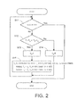
FIG. 2 is a flowchart illustrating valve control. -
FIG. 3 is a flowchart illustrating valve control provided with a warm-up shortening function. -
FIG. 4 is a schematic drawing of a waste heat recovering device of another embodiment. -
FIG. 5 is a flowchart illustrating valve control. -
FIG. 6 shows an example of heat exchanger arrangement. -
FIG. 7 shows an example of heat exchanger arrangement. -
- 10
- waste heat recovering device
- 11
- internal combustion engine
- 12
- high-temperature heat exchanger
- 13a, 13b
- low-temperature heat exchanger
- 14
- expander
- 15
- working fluid circulation flow path
- 16
- low-temperature heat exchanger group
- 17
- flow rate control valve
- 18
- controller (control means)
- 24
- first bypass flow path
- 25
- first bypass valve
- 30
- second bypass flow path
- 31
- second bypass valve
- The preferred embodiment of the present invention will be described below in greater detail with reference to the appended drawings.
- As shown in
FIG. 1 , a wasteheat recovering device 10 according to the present embodiment serves to recover waste heat of an internal combustion engine (diesel engine and the like) 11 installed on a vehicle. The waste heat recovering device is provided with anexpander 14 driven by steam generated by the below-described high-temperature heat exchanger 12 and low-temperature heat exchangers expander 14, and the electric power generated by the generator is consumed for driving various devices by the below-describedcontroller 18 and accumulated by a battery. - The waste
heat recovering device 10 of the present embodiment includes a working fluidcirculation flow path 15 in which the working fluid of theexpander 14 is caused to circulate, a high-temperature heat exchanger 12 for heating the working fluid flowing in the working fluidcirculation flow path 15 by a high-temperature fluid, a low-temperatureheat exchanger group 16 having, for each low-temperature fluid, a low-temperature heat exchanger circulation flow path 15 by any one of the low-temperature fluids, the low-temperature heat exchangers rate control valve 17 that controls a flow rate of the working fluid flowing into each low-temperature heat exchanger heat exchanger group 16, and control means (controller) for controlling the flowrate control valve 17. - In the present embodiment, the low-temperature heat exchanger group 16 (low-
temperature heat exchangers circulation flow path 15 on the working fluid upstream side of the high-temperature heat exchanger 12. By so disposing the low-temperature heat exchangers temperature heat exchanger 12, it is possible to increase the recovery efficiency of waste heat by further heating with the high-temperature fluid the working fluid that has been heated by the low-temperature fluid. - In the present embodiment, various heat sources (fluids) in the
internal combustion engine 11 are divided (grouped) into low-temperature fluids and high-temperature fluids on the basis the temperature (release temperature) of these heat sources and the target cooling temperature. - Examples of heat sources in the
internal combustion engine 11 include exhaust gas (release temperature: 300°C to 400°C, target cooling temperature: not specified) from theinternal combustion engine 11, cooling water (release temperature: approximately 80°C, target cooling temperature: approximately 60°C) of theinternal combustion engine 11, oils (engine oil, power steering oil, transmission oil, and the like) (release temperature: approximately 80°C, target cooling temperature: approximately 60°C) of theinternal combustion engine 11, and intake air (release temperature: approximately 120°C, target cooling temperature: as low as possible) pressurized by a turbocharger compressor. - Fluids (cooling water, oil, intake air, and the like), other than the exhaust gas, have no significant difference in temperature. In other words, each fluids (cooling water, oil, intake air, and the like), other than the exhaust gas, have almost the same temperature and the temperature thereof is lower than that of the exhaust gas. Therefore, in the present embodiment, these cooling water, oil, intake air, and the like are classified as low-temperature fluids and flow in parallel to each other in the low-
temperature heat exchangers FIG. 6 andFIG. 7 ). In other words, in the present embodiment, the low-temperature heat exchangers circulation flow path 15 by the cooling water, oil, intake air, and the like. - The exhaust gas temperature is higher than that of the cooling water, oil, intake air, and the like. Accordingly, in the present embodiment, the exhaust gas is classified as a high-temperature fluid and flows in the high-temperature heat exchanger 12 (see
FIG. 6 andFIG. 7 ). In other words, in the present embodiment, the high-temperature heat exchanger 12 heats the working fluid flowing in the working fluidcirculation flow path 15 by the exhaust gas. - The EGR gas (release temperature: 300°C to 400°C, target cooling temperature: as low as possible) has a temperature higher than that of the cooling water, oil, intake air, and the like, but almost equal to that of the exhaust gas. However, the target cooling temperature of the EGR gas is lower than the target cooling temperature of the exhaust gas and almost equal to the target cooling temperature of the cooling water, oil, intake air, and the like. Accordingly, a
heat exchanger 19 is disposed in parallel with the low-temperature heat exchangers temperature heat exchanger 12 in the working fluidcirculation flow path 15 and heat from the EGR gas is assumed to be recovered by the working fluid in the heat exchanger 19 (seeFIG. 6 ). Further, the heat can be also assumed to be recovered from the EGR gas in two stages, the EGR gas on the gas downstream side being classified as a low-temperature fluid and the EGR gas on the gas upstream side being classified as a high-temperature fluid (seeFIG. 7 ). When a plurality of high-temperature fluids are set, a plurality of high-temperature heat exchangers 12 are arranged in parallel with each other in the working fluidcirculation flow path 15 and a high-temperature heat exchanger group is constituted by these high-temperature heat exchangers 12. - A flow
rate control valve 17 is installed in a branchingpoint 20 of the working fluidcirculation flow path 15 linked to the low-temperature heat exchangers rate control valve 17. -
First temperature sensors temperature heat exchangers heat exchanger group 16 and asecond temperature sensor 23 that detects the working fluid temperature on the upstream side of the low-temperatureheat exchanger group 16 are provided in the working fluidcirculation flow path 15. - Further, the waste
heat recovering device 10 according to the present embodiment also includes a firstbypass flow path 24 that branches off the working fluidcirculation flow path 15 and bypasses the low-temperatureheat exchanger group 16 and afirst bypass valve 25 that is selectively switched between a position in which the working fluid is caused to flow in the low-temperatureheat exchanger group 16 and a position in which the working fluid is caused to flow in the firstbypass flow path 24. A switching valve is used as thefirst bypass valve 25. - The working fluid is supplied by a
pump 26 to the low-temperature heat exchangers temperature heat exchanger 12. The working fluid that has driven theexpander 14 is cooled by a running air flow in acondenser 27, supplied to thepump 26, and circulated by thepump 26. - Valve control performed by the
controller 18 will be explained below with reference toFIG. 2 . - The processing flow shown in
FIG. 2 is executed when an ignition key is not OFF (S11 inFIG. 2 ), that is, when theinternal combustion engine 11 operates. - In the processing flow shown in
FIG. 2 , when the working fluid outlet temperatures T1, T2 of the low-temperature heat exchangers first temperature sensors heat exchanger group 16 detected by the second temperature sensor 23 (S12 inFIG. 2 ; T1 > T3 or T2 > T3), thecontroller 18 switches thefirst bypass valve 25 to the A side of the low-temperature heat exchanger group 16 (S13 inFIG. 2 ), supplies the working fluid to the low-temperature heat exchangers heat exchanger group 16, and adjusts the opening degree of the flowrate control valve 17 so that the working fluid outlet temperatures T1, T2 of the low-temperature heat exchangers FIG. 2 ). As a result, even when heat amounts exchanged by the low-temperature heat exchangers heat exchanger group 16 are somewhat different, the flow rate of the working fluid flowing to the low-temperature heat exchangers heat exchanger group 16 is controlled by the flowrate control valve 17 and the working fluid outlet temperatures T1, T2 of the low-temperature heat exchangers - When the working fluid outlet temperatures T1, T2 of the low-
temperature heat exchangers first temperature sensors heat exchanger group 16 detected by thesecond temperature sensor 23, thecontroller 18 switches thefirst bypass valve 25 to the B side of the first bypass flow path 24 (S14 inFIG. 2 ) and causes the working fluid to circulate by bypassing the low-temperature heat exchanger group 16 (low-temperature heat exchangers - In the processing flow shown in
FIG. 3 , a warm-up shortening function is added to the processing flow shown inFIG. 2 . - In the processing flow shown in
FIG. 3 , even when the working fluid outlet temperatures T1, T2 of the low-temperature heat exchangers first temperature sensors heat exchanger group 16 detected by thesecond temperature sensor 23, where the working fluid outlet temperatures T1, T2 of the low-temperature heat exchangers first temperature sensors FIG. 3 ; T1 < TT and T2 < TT) and a warm-up mode allowed flag is true (FH = True), thecontroller 18 switches thefirst bypass valve 25 to the A side of the low-temperature heat exchanger group 16 (S13 inFIG. 3 ) and supplies the working fluid to the low-temperature heat exchangers heat exchanger group 16. As a result, the time required for warm-up operation can be shortened by canceling the bypass when the temperature of a low-temperature heat source such as cooling water is lower than a predetermined value, for example, when the engine is started, and heating the cooling water with the working fluid. - A special switch that can switch the warm-up mode allowed flag, so that the driver can select whether to allow the warm-up mode, can be disposed in a meter unit of a driver seat. A means for switching the warm-up mode allowed flag is not limited to the aforementioned special switch.
- A waste
heat recovering device 10 according to another embodiment will be explained below with reference toFIG. 4 . -
FIG. 4 is a schematic drawing of a waste heat recovering device according to another embodiment. Components identical to those shown inFIG. 1 are assigned with same reference symbols and explanation thereof is herein omitted. - A
second temperature sensor 28 that detects a working fluid outlet temperature of the high-temperature heat exchanger 12 and apressure sensor 29 that detects a working fluid outlet pressure of the high-temperature heat exchanger 12 are provided in the working fluidcirculation flow path 15. - The waste
heat recovering device 10 according to the present embodiment includes a secondbypass flow path 30 that branches off the working fluidcirculation flow path 15 and bypasses the high-temperature heat exchanger 12 and theexpander 14 and asecond bypass valve 31 that is selectively switched between a position in which the working fluid is caused to flow in the high-temperature heat exchanger 12 and a position in which the working fluid is caused to flow in the secondbypass flow path 30. A directional flow rate control valve or a valve similar thereto can be used as thesecond bypass valve 31. - Valve control performed by the
controller 18 will be explained with reference toFIG. 5 . Only the difference between this control and the processing flow shown inFIG. 3 will be explained. - In the processing flow shown in
FIG. 5 , when an external error signal indicating the occurrence of overheating in theinternal combustion engine 11 is not inputted (S17 inFIG. 5 ), thecontroller 18 switches thesecond bypass valve 31 to the A side of the high-temperature heat exchanger 12 (S18 inFIG. 5 ) and supplies the working fluid to the high-temperature heat exchanger 12. - When a working fluid outlet temperature T4 of the high-
temperature heat exchanger 12 detected by thesecond temperature sensor 28 is higher than a predetermined allowed maximum temperature TLIMIT (T4 > TLIMIT), or when a working fluid outlet pressure P1 of the high-temperature heat exchanger 12 detected by thepressure sensor 29 is higher than a predetermined allowed maximum pressure PLIMIT (P1 > PLIMIT), or when a temperature T3 of the working fluid on the upstream side of the low-temperatureheat exchanger group 16 detected by thesecond temperature sensor 23 is higher than a predetermined target temperature TC (T3 > TC) (S19 inFIG. 5 ), thecontroller 18 adjusts the opening degree of thesecond bypass valve 31 so as to increase the flow rate of the working fluid flowing in the high-temperature heat exchanger 12 (S20 inFIG. 5 ). As a result damage of the high-temperature heat exchanger 12 and the like can be prevented. When the conditions shown in S24 inFIG. 5 are not fulfilled, thecontroller 18 adjusts the opening degree of thesecond bypass valve 31 so that a working fluid outlet temperature T4 of the high-temperature heat exchanger 12 becomes a predetermined maximum temperature target value TTARGET (S21 inFIG. 5 ). As a result, a larger amount of heat can be recovered and waste heat can be recovered with good efficiency. - When the external error signal indicating the occurrence of overheating in the
internal combustion engine 11 is inputted (S17 inFIG. 5 ), thecontroller 18 switches thesecond bypass valve 31 to the B side of the second bypass flow path 30 (S22, S23 inFIG. 5 ) and causes the working fluid to circulate by bypassing the high-temperature heat exchanger 12 and theexpander 14. As a result, heat recovery from the high-temperature fluid such as exhaust gas is stopped and circulation velocity of the working fluid is increased, thereby making it possible to cool efficiently the cooling water or the like in the low-temperature heat exchangers - The preferred embodiments of the present invention are explained above, but the present invention is not limited to these embodiments and a variety of other embodiments can be employed.
Claims (5)
- A waste heat recovering device for driving an expander by evaporating a working fluid by waste heat of an internal combustion engine, comprising:a working fluid circulation flow path in which the working fluid of the expander is caused to circulate;a high-temperature heat exchanger for heating the working fluid flowing in the working fluid circulation flow path by a high-temperature fluid such as exhaust gas of the internal combustion engine;a low-temperature heat exchanger group having, for each of low-temperature fluids such as cooling water and oil of the internal combustion engine, a low-temperature heat exchanger for heating the working fluid flowing in the working fluid circulation flow path by any one of the low-temperature fluids, the low-temperature heat exchangers being disposed in parallel with each other;a flow rate control valve that controls a flow rate of the working fluid flowing into each low-temperature heat exchanger of the low-temperature heat exchanger group; andcontrol means for controlling the flow rate control valve.
- The waste heat recovering device according to claim 1,
wherein the low-temperature heat exchanger group is installed in the working fluid circulation flow path on a working fluid upstream side of the high-temperature heat exchanger. - The waste heat recovering device according to claim 1 or 2, comprising a first bypass flow path that branches off the working fluid circulation flow path and bypasses the low-temperature heat exchanger group, and a first bypass valve that is selectively switched between a position in which the working fluid is caused to flow in the low-temperature heat exchanger group and a position in which the working fluid is caused to flow in the first bypass flow path.
- The waste heat recovering device according to any one of claims 1 to 3, comprising a second bypass flow path that branches off the working fluid circulation flow path and bypasses the high-temperature heat exchanger, and a second bypass valve that is selectively switched between a position in which the working fluid is caused to flow in the high-temperature heat exchanger and a position in which the working fluid is caused to flow in the second bypass flow path.
- The waste heat recovering device according to any one of claims 1 to 4, wherein each low-temperature heat exchanger of the low-temperature heat exchanger group heats the working fluid flowing in the working fluid circulation flow path by a fluid at approximately the same temperature.
Applications Claiming Priority (2)
| Application Number | Priority Date | Filing Date | Title |
|---|---|---|---|
| JP2008083483A JP5018592B2 (en) | 2008-03-27 | 2008-03-27 | Waste heat recovery device |
| PCT/JP2009/052673 WO2009119185A1 (en) | 2008-03-27 | 2009-02-17 | Waste heat recovering device |
Publications (1)
| Publication Number | Publication Date |
|---|---|
| EP2280152A1 true EP2280152A1 (en) | 2011-02-02 |
Family
ID=41113393
Family Applications (1)
| Application Number | Title | Priority Date | Filing Date |
|---|---|---|---|
| EP09724074A Withdrawn EP2280152A1 (en) | 2008-03-27 | 2009-02-17 | Waste heat recovering device |
Country Status (5)
| Country | Link |
|---|---|
| US (1) | US8567193B2 (en) |
| EP (1) | EP2280152A1 (en) |
| JP (1) | JP5018592B2 (en) |
| CN (1) | CN101978140B (en) |
| WO (1) | WO2009119185A1 (en) |
Cited By (5)
| Publication number | Priority date | Publication date | Assignee | Title |
|---|---|---|---|---|
| AT512921A4 (en) * | 2012-07-31 | 2013-12-15 | Man Truck & Bus Oesterreich Ag | Method for controlling a heat recovery system in a motor vehicle |
| EP2397659A3 (en) * | 2010-06-21 | 2015-07-29 | Paccar Inc. | Dual cycle rankine waste heat recovery cycle |
| EP2843222A4 (en) * | 2012-04-23 | 2016-02-24 | Toyota Motor Co Ltd | HEAT TRANSFER DEVICE |
| EP3273017A1 (en) * | 2016-07-19 | 2018-01-24 | MAN Truck & Bus Österreich GesmbH | Device for generating usable energy |
| US10830121B2 (en) | 2016-01-15 | 2020-11-10 | Scania Cv Ab | Cooling system for a combustion engine and a WHR system |
Families Citing this family (72)
| Publication number | Priority date | Publication date | Assignee | Title |
|---|---|---|---|---|
| US7866157B2 (en) | 2008-05-12 | 2011-01-11 | Cummins Inc. | Waste heat recovery system with constant power output |
| DE102009020615A1 (en) * | 2009-05-09 | 2010-11-11 | Daimler Ag | Exhaust gas heat recovery in motor vehicles |
| US8544274B2 (en) | 2009-07-23 | 2013-10-01 | Cummins Intellectual Properties, Inc. | Energy recovery system using an organic rankine cycle |
| US8627663B2 (en) | 2009-09-02 | 2014-01-14 | Cummins Intellectual Properties, Inc. | Energy recovery system and method using an organic rankine cycle with condenser pressure regulation |
| US8413434B2 (en) * | 2009-10-21 | 2013-04-09 | GM Global Technology Operations LLC | Exhaust heat recovery for transmission warm-up |
| JP2011106302A (en) * | 2009-11-13 | 2011-06-02 | Mitsubishi Heavy Ind Ltd | Engine waste heat recovery power-generating turbo system and reciprocating engine system including the same |
| CN103237961B (en) | 2010-08-05 | 2015-11-25 | 康明斯知识产权公司 | Adopt the critical supercharging cooling of the discharge of organic Rankine bottoming cycle |
| CN103180553B (en) | 2010-08-09 | 2015-11-25 | 康明斯知识产权公司 | Comprise Waste Heat Recovery System (WHRS) and the internal-combustion engine system of rankine cycle RC subtense angle |
| WO2012021757A2 (en) | 2010-08-11 | 2012-02-16 | Cummins Intellectual Property, Inc. | Split radiator design for heat rejection optimization for a waste heat recovery system |
| CN103180554B (en) | 2010-08-13 | 2016-01-20 | 康明斯知识产权公司 | Rankine Cycle Condenser Pressure Control Using Transducer Bypass Valve |
| JP5481737B2 (en) * | 2010-09-30 | 2014-04-23 | サンデン株式会社 | Waste heat utilization device for internal combustion engine |
| US8844291B2 (en) | 2010-12-10 | 2014-09-30 | Vaporgenics Inc. | Universal heat engine |
| WO2012081854A2 (en) * | 2010-12-17 | 2012-06-21 | 삼성중공업주식회사 | Waste heat recovery device for a marine vessel |
| US9464539B2 (en) | 2010-12-17 | 2016-10-11 | Samsung Heavy Ind. Co., Ltd | Waste heat recovery device for a marine vessel |
| DE112011104516B4 (en) | 2010-12-23 | 2017-01-19 | Cummins Intellectual Property, Inc. | System and method for regulating EGR cooling using a Rankine cycle |
| US8826662B2 (en) | 2010-12-23 | 2014-09-09 | Cummins Intellectual Property, Inc. | Rankine cycle system and method |
| DE102012000100A1 (en) | 2011-01-06 | 2012-07-12 | Cummins Intellectual Property, Inc. | Rankine cycle-HEAT USE SYSTEM |
| WO2012096958A1 (en) | 2011-01-10 | 2012-07-19 | Cummins Intellectual Property, Inc. | Rankine cycle waste heat recovery system |
| US8919328B2 (en) | 2011-01-20 | 2014-12-30 | Cummins Intellectual Property, Inc. | Rankine cycle waste heat recovery system and method with improved EGR temperature control |
| WO2012150994A1 (en) | 2011-02-28 | 2012-11-08 | Cummins Intellectual Property, Inc. | Engine having integrated waste heat recovery |
| CN102174906B (en) * | 2011-03-16 | 2013-10-16 | 北京工业大学 | Automobile eddy current retarder breaking heat energy recycling device and control method |
| CN102322692A (en) * | 2011-05-30 | 2012-01-18 | 湖南科技大学 | Tail gas heat utilization method for low-concentration gas heat countercurrent catalytic oxidation apparatus |
| JP2012251517A (en) * | 2011-06-06 | 2012-12-20 | Toyota Industries Corp | Waste heat recovery apparatus |
| WO2013028166A2 (en) * | 2011-08-22 | 2013-02-28 | International Engine Intellectual Property Company, Llc | Waste heat recovery system for controlling egr outlet temperature |
| JP2014231737A (en) * | 2011-09-22 | 2014-12-11 | 株式会社豊田自動織機 | Rankine cycle device |
| JP2013076374A (en) * | 2011-09-30 | 2013-04-25 | Nissan Motor Co Ltd | Rankine cycle and heat exchanger used for the same |
| JP5804879B2 (en) * | 2011-09-30 | 2015-11-04 | 日産自動車株式会社 | Waste heat utilization equipment |
| CN103748347B (en) * | 2011-09-30 | 2015-08-19 | 日产自动车株式会社 | Rankine cycle |
| JP5716837B2 (en) * | 2011-09-30 | 2015-05-13 | 日産自動車株式会社 | Engine waste heat utilization device |
| JP2013096322A (en) * | 2011-11-02 | 2013-05-20 | Toyota Industries Corp | Waste-heat regenerating system |
| US8931275B2 (en) * | 2012-01-24 | 2015-01-13 | GM Global Technology Operations LLC | Adaptive heat exchange architecture for optimum energy recovery in a waste heat recovery architecture |
| US9739243B2 (en) * | 2012-02-10 | 2017-08-22 | Ford Gloabl Technologies, LLC | Methods and systems for fuel vapor control |
| DE102012204126A1 (en) | 2012-03-15 | 2013-09-19 | Eberspächer Exhaust Technology GmbH & Co. KG | Steam generator for a Rankine process |
| CN104254672B (en) * | 2012-02-16 | 2017-03-08 | 埃贝斯佩歇废气技术合资公司 | Steam generator system, waste heat recovery plant and internal combustion engine |
| JP6135256B2 (en) * | 2012-05-23 | 2017-05-31 | 株式会社デンソー | Thermal management system for vehicles |
| US8893495B2 (en) | 2012-07-16 | 2014-11-25 | Cummins Intellectual Property, Inc. | Reversible waste heat recovery system and method |
| JP6371770B2 (en) * | 2012-10-17 | 2018-08-08 | ノアグレン リミテッド | Fluid control module for waste heat recovery system |
| CN103615338A (en) * | 2012-11-12 | 2014-03-05 | 摩尔动力(北京)技术股份有限公司 | Double-working-medium power system capable of utilizing waste heat of internal combustion engine |
| US9140209B2 (en) * | 2012-11-16 | 2015-09-22 | Cummins Inc. | Rankine cycle waste heat recovery system |
| JP2016507687A (en) * | 2012-12-19 | 2016-03-10 | マック トラックス インコーポレイテッド | Device and method for stopping inflow of hydraulic fluid in exhaust heat recovery device |
| EP2936037B1 (en) | 2012-12-19 | 2019-02-13 | Mack Trucks, Inc. | Series parallel waste heat recovery system |
| JP2016033331A (en) * | 2012-12-27 | 2016-03-10 | 株式会社豊田自動織機 | Internal combustion engine exhaust heat utilization device |
| BR112015018789B1 (en) * | 2013-02-06 | 2022-03-22 | Volvo Truck Corporation | Waste heat recovery device |
| US9702358B2 (en) * | 2013-03-15 | 2017-07-11 | Ingersoll-Rand Company | Temperature control for compressor |
| US9845711B2 (en) | 2013-05-24 | 2017-12-19 | Cummins Inc. | Waste heat recovery system |
| US9593597B2 (en) | 2013-05-30 | 2017-03-14 | General Electric Company | System and method of waste heat recovery |
| US9587520B2 (en) | 2013-05-30 | 2017-03-07 | General Electric Company | System and method of waste heat recovery |
| US9145795B2 (en) | 2013-05-30 | 2015-09-29 | General Electric Company | System and method of waste heat recovery |
| US9732662B2 (en) * | 2013-06-14 | 2017-08-15 | GM Global Technology Operations LLC | Coolant control systems and methods for transmission temperature regulation |
| CN103352772B (en) * | 2013-06-25 | 2015-08-19 | 天津大学 | The combined cycle thermoelectric converting system of internal-combustion engine many grades UTILIZATION OF VESIDUAL HEAT IN |
| US9926811B2 (en) * | 2013-09-05 | 2018-03-27 | Echogen Power Systems, Llc | Control methods for heat engine systems having a selectively configurable working fluid circuit |
| CA2924625A1 (en) * | 2013-10-31 | 2015-05-07 | The Chugoku Electric Power Co., Inc. | Exhaust heat recovery apparatus of engine |
| JP6307161B2 (en) * | 2013-11-26 | 2018-04-04 | ボルボ トラック コーポレイション | Auxiliary heating in waste heat recovery |
| CN103742292B (en) * | 2013-12-27 | 2015-05-13 | 天津大学 | Exhaust gas waste heat recovery system of two-stroke internal combustion engine |
| CN103742293B (en) * | 2013-12-27 | 2015-05-13 | 天津大学 | Internal combustion engine vapor supercharging waste heat recovery system |
| CN103711555B (en) * | 2013-12-27 | 2016-05-25 | 天津大学 | Afterheat of IC engine double loop cascade utilization system |
| JP6217426B2 (en) * | 2014-02-07 | 2017-10-25 | いすゞ自動車株式会社 | Waste heat recovery system |
| DE102014006909B3 (en) * | 2014-05-09 | 2015-07-09 | Maschinenwerk Misselhorn Mwm Gmbh | Arrangement with several heat exchangers and method for vaporizing a working medium |
| US20170201158A1 (en) * | 2014-05-30 | 2017-07-13 | Leartek Pty Ltd | Exhaust heat recovery system control method and device |
| JP2016014339A (en) * | 2014-07-01 | 2016-01-28 | いすゞ自動車株式会社 | Waste heat regeneration system |
| JP6566252B2 (en) * | 2014-08-27 | 2019-08-28 | 日本製鉄株式会社 | Heat recovery method, heat recovery apparatus used therefor, and carbon dioxide separation and recovery method |
| BE1022434B1 (en) * | 2014-08-29 | 2016-03-30 | Atlas Copco Airpower Naamloze Vennootschap | COMPRESSOR INSTALLATION |
| JP6315814B2 (en) * | 2014-09-17 | 2018-04-25 | 株式会社神戸製鋼所 | Energy recovery device, compression device, and energy recovery method |
| DE102014016868A1 (en) * | 2014-11-14 | 2016-05-19 | Interimo GmbH | Method for operating a low-temperature power plant with an evaporator circuit process as a working cycle |
| US9650941B2 (en) * | 2014-12-16 | 2017-05-16 | Ford Global Technologies, Llc | Rankine cycle for a vehicle |
| US10914201B2 (en) | 2015-12-18 | 2021-02-09 | Cummins Inc. | Integrated cooling system for engine and waste heat recovery |
| CN108884727B (en) * | 2016-03-30 | 2020-11-06 | 三菱重工业株式会社 | Plant and method for operating the same |
| WO2017218322A1 (en) * | 2016-06-14 | 2017-12-21 | Borgwarner Inc. | Waste heat recovery system with parallel evaporators and method of operating |
| JP6847682B2 (en) * | 2017-01-31 | 2021-03-24 | 三菱重工業株式会社 | How to operate a waste power plant and a waste power plant |
| US11137177B1 (en) | 2019-03-16 | 2021-10-05 | Vaporgemics, Inc | Internal return pump |
| UA141780U (en) * | 2019-10-21 | 2020-04-27 | Іван Іванович Котурбач | DIESEL-STEAM POWER PLANT |
| JP2022146033A (en) * | 2021-03-22 | 2022-10-05 | いすゞ自動車株式会社 | trilateral cycle system |
Family Cites Families (16)
| Publication number | Priority date | Publication date | Assignee | Title |
|---|---|---|---|---|
| US4031705A (en) * | 1974-11-15 | 1977-06-28 | Berg John W | Auxiliary power system and apparatus |
| US4276747A (en) * | 1978-11-30 | 1981-07-07 | Fiat Societa Per Azioni | Heat recovery system |
| JPS6066099A (en) * | 1983-09-21 | 1985-04-16 | Hitachi Ltd | Temperature balance control of multistage heat exchanger |
| GB2195264B (en) | 1986-09-09 | 1990-10-24 | Norsolor Sa | A process for regenerating a catalyst and its application to an oxidative dehydrogenation process |
| JPH01267306A (en) * | 1988-04-15 | 1989-10-25 | Toshiba Corp | Flow controller for heat exchanger |
| JPH03237256A (en) * | 1990-02-14 | 1991-10-23 | Nkk Corp | High-efficiency waste heat recovery system of Cozy Energy System |
| JPH045461A (en) * | 1990-04-19 | 1992-01-09 | Yanmar Diesel Engine Co Ltd | Waste heat recovering device for internal combustion engine |
| JP3631521B2 (en) * | 1995-03-06 | 2005-03-23 | 日産ディーゼル工業株式会社 | Cogeneration system cooling water circuit equipment |
| DE60123987T2 (en) * | 2000-10-10 | 2007-02-01 | Honda Giken Kogyo K.K. | RANKINE CIRCULAR DEVICE FOR INTERNAL COMBUSTION ENGINE |
| JP2003247750A (en) * | 2002-02-25 | 2003-09-05 | Shinko Electric Co Ltd | Co-generator, hot water supply system and engine warm-up system |
| JP2004257601A (en) | 2003-02-25 | 2004-09-16 | Fuji Photo Film Co Ltd | Waste heat collecting system |
| JP4140543B2 (en) * | 2004-03-24 | 2008-08-27 | 株式会社デンソー | Waste heat utilization equipment |
| JP2007211681A (en) * | 2006-02-09 | 2007-08-23 | Sanden Corp | Power recovery system |
| US8561405B2 (en) * | 2007-06-29 | 2013-10-22 | General Electric Company | System and method for recovering waste heat |
| JP2008038916A (en) * | 2007-09-28 | 2008-02-21 | Denso Corp | Rankine cycle |
| US7866157B2 (en) * | 2008-05-12 | 2011-01-11 | Cummins Inc. | Waste heat recovery system with constant power output |
-
2008
- 2008-03-27 JP JP2008083483A patent/JP5018592B2/en not_active Expired - Fee Related
-
2009
- 2009-02-17 US US12/934,114 patent/US8567193B2/en not_active Expired - Fee Related
- 2009-02-17 EP EP09724074A patent/EP2280152A1/en not_active Withdrawn
- 2009-02-17 WO PCT/JP2009/052673 patent/WO2009119185A1/en not_active Ceased
- 2009-02-17 CN CN200980110255.0A patent/CN101978140B/en not_active Expired - Fee Related
Non-Patent Citations (1)
| Title |
|---|
| See references of WO2009119185A1 * |
Cited By (8)
| Publication number | Priority date | Publication date | Assignee | Title |
|---|---|---|---|---|
| EP2397659A3 (en) * | 2010-06-21 | 2015-07-29 | Paccar Inc. | Dual cycle rankine waste heat recovery cycle |
| EP2843222A4 (en) * | 2012-04-23 | 2016-02-24 | Toyota Motor Co Ltd | HEAT TRANSFER DEVICE |
| AT512921A4 (en) * | 2012-07-31 | 2013-12-15 | Man Truck & Bus Oesterreich Ag | Method for controlling a heat recovery system in a motor vehicle |
| AT512921B1 (en) * | 2012-07-31 | 2013-12-15 | Man Truck & Bus Oesterreich Ag | Method for controlling a heat recovery system in a motor vehicle |
| EP2693001A1 (en) * | 2012-07-31 | 2014-02-05 | MAN Truck & Bus Österreich AG | Method for regulating a heat recovery system in a motor vehicle |
| CN103573468A (en) * | 2012-07-31 | 2014-02-12 | 曼卡车和巴士奥地利股份公司 | Method for regulating heat recovery system in motor vehicle |
| US10830121B2 (en) | 2016-01-15 | 2020-11-10 | Scania Cv Ab | Cooling system for a combustion engine and a WHR system |
| EP3273017A1 (en) * | 2016-07-19 | 2018-01-24 | MAN Truck & Bus Österreich GesmbH | Device for generating usable energy |
Also Published As
| Publication number | Publication date |
|---|---|
| JP5018592B2 (en) | 2012-09-05 |
| US8567193B2 (en) | 2013-10-29 |
| CN101978140A (en) | 2011-02-16 |
| JP2009236014A (en) | 2009-10-15 |
| CN101978140B (en) | 2014-03-12 |
| WO2009119185A1 (en) | 2009-10-01 |
| US20110005477A1 (en) | 2011-01-13 |
Similar Documents
| Publication | Publication Date | Title |
|---|---|---|
| US8567193B2 (en) | Waste heat recovering device | |
| EP2959145B1 (en) | System for recuperating heat from the exhaust gases in an internal combustion engine, with two heat exchangers on a gas recirculation circuit | |
| CN103180554B (en) | Rankine Cycle Condenser Pressure Control Using Transducer Bypass Valve | |
| US20140311141A1 (en) | Waste heat utilization apparatus | |
| CN204109739U (en) | Vehicular heating system | |
| JP4089539B2 (en) | Rankine cycle | |
| US20090241543A1 (en) | Rankine cycle load limiting through use of a recuperator bypass | |
| WO2012019161A1 (en) | Emissions-critical charge cooling using an organic rankine cycle | |
| JP2014504345A (en) | Thermoelectric recovery of engine fluid and Peltier heating | |
| JP2008038916A (en) | Rankine cycle | |
| EP2998536B1 (en) | An arrangement and a control method of an engine cooling system | |
| JP6157733B2 (en) | Internal combustion engine arrangement with waste heat recovery system and control process of waste heat recovery system | |
| US20190128146A1 (en) | Heat cycle system | |
| JP6382219B2 (en) | Series parallel waste heat recovery system | |
| EP3411586B1 (en) | A method for controlling the temperature of a waste heat recovery system and such a waste heat recovery system | |
| KR101779273B1 (en) | Engine intake air thermal management device and associated thermal management method | |
| JP2018062909A (en) | Waste heat recovery power generation device | |
| JP2011052662A (en) | Waste heat recovery device for vehicle | |
| JP6327292B2 (en) | Control device for internal combustion engine | |
| JP2013092106A (en) | Exhaust gas cleaning device for internal combustion engine | |
| RU2280777C1 (en) | Power plant | |
| JP2004132189A (en) | Thermal storage system for vehicle | |
| JP2010138697A (en) | Rankine cycle system | |
| JP6066875B2 (en) | Waste heat recovery device for internal combustion engine | |
| EP2789811B1 (en) | System for heat recovery of a combustion engine |
Legal Events
| Date | Code | Title | Description |
|---|---|---|---|
| PUAI | Public reference made under article 153(3) epc to a published international application that has entered the european phase |
Free format text: ORIGINAL CODE: 0009012 |
|
| 17P | Request for examination filed |
Effective date: 20101014 |
|
| AK | Designated contracting states |
Kind code of ref document: A1 Designated state(s): AT BE BG CH CY CZ DE DK EE ES FI FR GB GR HR HU IE IS IT LI LT LU LV MC MK MT NL NO PL PT RO SE SI SK TR |
|
| AX | Request for extension of the european patent |
Extension state: AL BA RS |
|
| DAX | Request for extension of the european patent (deleted) | ||
| STAA | Information on the status of an ep patent application or granted ep patent |
Free format text: STATUS: THE APPLICATION HAS BEEN WITHDRAWN |
|
| 18W | Application withdrawn |
Effective date: 20160311 |