EP2279840A1 - Method for the manufacture of a ceramic product and plant implementing the method. - Google Patents
Method for the manufacture of a ceramic product and plant implementing the method. Download PDFInfo
- Publication number
- EP2279840A1 EP2279840A1 EP10170337A EP10170337A EP2279840A1 EP 2279840 A1 EP2279840 A1 EP 2279840A1 EP 10170337 A EP10170337 A EP 10170337A EP 10170337 A EP10170337 A EP 10170337A EP 2279840 A1 EP2279840 A1 EP 2279840A1
- Authority
- EP
- European Patent Office
- Prior art keywords
- product
- mould
- points
- drying
- plant
- Prior art date
- Legal status (The legal status is an assumption and is not a legal conclusion. Google has not performed a legal analysis and makes no representation as to the accuracy of the status listed.)
- Granted
Links
Images

Classifications
-
- B—PERFORMING OPERATIONS; TRANSPORTING
- B28—WORKING CEMENT, CLAY, OR STONE
- B28B—SHAPING CLAY OR OTHER CERAMIC COMPOSITIONS; SHAPING SLAG; SHAPING MIXTURES CONTAINING CEMENTITIOUS MATERIAL, e.g. PLASTER
- B28B11/00—Apparatus or processes for treating or working the shaped or preshaped articles
- B28B11/24—Apparatus or processes for treating or working the shaped or preshaped articles for curing, setting or hardening
- B28B11/243—Setting, e.g. drying, dehydrating or firing ceramic articles
-
- B—PERFORMING OPERATIONS; TRANSPORTING
- B28—WORKING CEMENT, CLAY, OR STONE
- B28B—SHAPING CLAY OR OTHER CERAMIC COMPOSITIONS; SHAPING SLAG; SHAPING MIXTURES CONTAINING CEMENTITIOUS MATERIAL, e.g. PLASTER
- B28B17/00—Details of, or accessories for, apparatus for shaping the material; Auxiliary measures taken in connection with such shaping
- B28B17/0063—Control arrangements
- B28B17/0081—Process control
-
- C—CHEMISTRY; METALLURGY
- C04—CEMENTS; CONCRETE; ARTIFICIAL STONE; CERAMICS; REFRACTORIES
- C04B—LIME, MAGNESIA; SLAG; CEMENTS; COMPOSITIONS THEREOF, e.g. MORTARS, CONCRETE OR LIKE BUILDING MATERIALS; ARTIFICIAL STONE; CERAMICS; REFRACTORIES; TREATMENT OF NATURAL STONE
- C04B33/00—Clay-wares
- C04B33/28—Slip casting
-
- C—CHEMISTRY; METALLURGY
- C04—CEMENTS; CONCRETE; ARTIFICIAL STONE; CERAMICS; REFRACTORIES
- C04B—LIME, MAGNESIA; SLAG; CEMENTS; COMPOSITIONS THEREOF, e.g. MORTARS, CONCRETE OR LIKE BUILDING MATERIALS; ARTIFICIAL STONE; CERAMICS; REFRACTORIES; TREATMENT OF NATURAL STONE
- C04B33/00—Clay-wares
- C04B33/30—Drying methods
-
- F—MECHANICAL ENGINEERING; LIGHTING; HEATING; WEAPONS; BLASTING
- F26—DRYING
- F26B—DRYING SOLID MATERIALS OR OBJECTS BY REMOVING LIQUID THEREFROM
- F26B21/00—Arrangements for supplying or controlling air or other gases for drying solid materials or objects
- F26B21/30—Controlling, e.g. regulating, parameters of gas supply
-
- F—MECHANICAL ENGINEERING; LIGHTING; HEATING; WEAPONS; BLASTING
- F26—DRYING
- F26B—DRYING SOLID MATERIALS OR OBJECTS BY REMOVING LIQUID THEREFROM
- F26B21/00—Arrangements for supplying or controlling air or other gases for drying solid materials or objects
- F26B21/50—Ducting arrangements from the source of air or other gases to the materials or objects being dried
-
- F—MECHANICAL ENGINEERING; LIGHTING; HEATING; WEAPONS; BLASTING
- F26—DRYING
- F26B—DRYING SOLID MATERIALS OR OBJECTS BY REMOVING LIQUID THEREFROM
- F26B5/00—Drying solid materials or objects by processes not involving the application of heat
- F26B5/14—Drying solid materials or objects by processes not involving the application of heat by applying pressure, e.g. wringing; by brushing; by wiping
-
- C—CHEMISTRY; METALLURGY
- C04—CEMENTS; CONCRETE; ARTIFICIAL STONE; CERAMICS; REFRACTORIES
- C04B—LIME, MAGNESIA; SLAG; CEMENTS; COMPOSITIONS THEREOF, e.g. MORTARS, CONCRETE OR LIKE BUILDING MATERIALS; ARTIFICIAL STONE; CERAMICS; REFRACTORIES; TREATMENT OF NATURAL STONE
- C04B2235/00—Aspects relating to ceramic starting mixtures or sintered ceramic products
- C04B2235/60—Aspects relating to the preparation, properties or mechanical treatment of green bodies or pre-forms
- C04B2235/602—Making the green bodies or pre-forms by moulding
- C04B2235/6027—Slip casting
-
- C—CHEMISTRY; METALLURGY
- C04—CEMENTS; CONCRETE; ARTIFICIAL STONE; CERAMICS; REFRACTORIES
- C04B—LIME, MAGNESIA; SLAG; CEMENTS; COMPOSITIONS THEREOF, e.g. MORTARS, CONCRETE OR LIKE BUILDING MATERIALS; ARTIFICIAL STONE; CERAMICS; REFRACTORIES; TREATMENT OF NATURAL STONE
- C04B2235/00—Aspects relating to ceramic starting mixtures or sintered ceramic products
- C04B2235/60—Aspects relating to the preparation, properties or mechanical treatment of green bodies or pre-forms
- C04B2235/606—Drying
-
- F—MECHANICAL ENGINEERING; LIGHTING; HEATING; WEAPONS; BLASTING
- F26—DRYING
- F26B—DRYING SOLID MATERIALS OR OBJECTS BY REMOVING LIQUID THEREFROM
- F26B2210/00—Drying processes and machines for solid objects characterised by the specific requirements of the drying goods
- F26B2210/02—Ceramic articles or ceramic semi-finished articles
Definitions
- This invention relates to a method for the manufacture of a ceramic product, in particular for the manufacture of ceramic sanitaryware.
- ceramic sanitaryware such as washbasins, toilet bowls, bidets and the like
- slip a liquid mixture, known as slip, consisting of water, clay and very small quantities of other substances, in moulds made of porous resin.
- the mould gives the article of sanitaryware the required shape and the article is then extracted from the mould in a solid, though plastic, form and further processed according to a well-known sequence of steps until it is completely finished.
- plants which include the mould, of the known type, and which are designed for a type of high pressure casting, in its simplest and most basic form, comprising the following sequence of steps:
- This type of casting allows the product "layer” to be formed in a relatively short time, reducing the overall time required for a product production cycle.
- the product just produced and removed from the mould should have enough mechanical strength to support its own weight during extraction from the mould and standing on a supporting surface.
- the product is extracted from the mould in a solid but "green” state (still having a water content of between 16 and 19% of its wet weight) and therefore it is still subject to plastic deformation.
- sanitaryware article contact with the air brings about two main changes in the structure/consistency of the article, the first bringing it to an intermediate "leatherhard” state (in which the water content is approximately halved in weight compared to the previous state) and the second, to an almost finished “whitehard” state (in which the water content is further reduced): in these two states, the sanitaryware article is much less subject to plastic deformation.
- the product passage from the green state to the whitehard state causes contractions in the product due to water loss and, therefore, a reduction in product dimensions.
- Such tensions may be generated by the difference in humidity along the layer formed, or by particular angles or radii formed on the product drying and where, basically, there are areas with a greater concentration of stresses, that is to say, which do not have enough mechanical strength to withstand peaks in tension greater than the acceptable load.
- Document DE 43 23 709 discloses a process for drying pre-cast ceramic products in a drying chamber.
- uniform drying is accomplished by feeding a liquid (water) to a ventilating device before and during drying so as to add it in the form of mist to the air flow blown into the drying chamber.
- Another liquid (oil) is added to this during the drying operation and, owing to its very nature, this settles evenly on the material to be dried: the combination of nebulised oil and water slows down the product drying process on the areas subjected to the direct action of the nebulised liquids and helps even out the product drying so as to prevent stress cracks.
- this type of drying treatment could not be used not only because of the more complex shape of the surface but also because of the lack of precision in directing the flow of nebulised liquids at the more delicate parts of the product.
- This invention therefore has for an aim to overcome these disadvantages by providing a method for the manufacture of a ceramic product with which it is possible to eliminate the risks of cracks developing in products removed from moulds rapidly and safely and without excessively affecting conventional operating times.
- This invention also has for an aim to provide a plant for implementing the method described above.
- the plant shall be very practical and have structures designed to allow both identification and reduction of the risks of cracks developing in the product removed from the mould, all without adding a large number of components in the plant stations.
- this aim is achieved by a method for the manufacture of ceramic products wherein the steps of casting a product in, and removing it from, a mould are followed by steps of identifying one or more points or areas of the product which have high concentrations of tensions or do not match reference parameters and applying a fluid flow localised around the identified point or points, at a predetermined temperature and for a predetermined time so as to accelerate drying and, therefore, hardening only at that point or those points relative to the rest of the product surface.
- This special procedure prior to normal drying in air, makes it possible to dry the more critical parts of the product rapidly, and only at certain points, compared to the other product surfaces, that is to say, more rapidly and precisely, in order to avoid stress cracks. In other terms, the drying treatment is accelerated and performed in point-by-point manner.
- the method according to this invention is used for manufacturing ceramic products, in particular, but without limiting its scope, ceramic sanitaryware (such as washbasins, washbasin columns, toilet bowls, bidets and the like) using a liquid mixture known as slip.
- ceramic sanitaryware such as washbasins, washbasin columns, toilet bowls, bidets and the like
- slip a liquid mixture known as slip.
- This plant labelled 7 as a whole, comprises at least one porous mould 1, for example made of porous resin ( Figure 1 ), comprising at least two parts 2 and 3 which, when joined together form a moulding cavity 4 for the product M and which can be joined together (arrows F2) and moved away from each other (arrows F1) by movement means.
- the mould 1 forms a toilet bowl M.
- This mould 1 has accessory elements, such as ducts for feeding and discharging the slip at predetermined pressures which are connected to a slip tank, and at least one control unit for the product M production cycle which is connected to the slip feed/discharge systems. Said elements are not illustrated, being of the known type and not strictly within the scope of the invention.
- the plant 7 has a supporting and drying station 8 for the product M removed from the mould 1.
- the station 8 has a base B for supporting the product M.
- the product is transferred to the station 8 by suitable robotised elements.
- the station 8 may also comprise additional product M supporting elements, not illustrated in the accompanying drawings, since they do not strictly fall within the scope of the invention.
- the method for manufacturing these ceramic products M comprises the steps of:
- the method according to the invention comprises:
- the method hinges on product M "point-by-point” drying based on predetermined parameters, to prevent or reduce the risk of cracks developing in the product M, through rapid acceleration of drying accompanied by a rapid increase in hardness.
- one of the reference parameters for the step of identifying points P or areas is the hardness D detected at the relative point P by means of elements 5 (described below).
- Another possible parameter which can be used for the step of identifying points P or areas is a statistical data item S detected which depends on the product M geometry.
- the parameter S is generated from the "history" of each type of product obtained and from its shape which, on each occasion, may have developed cracks at certain points or areas during the drying step and which, therefore, is detected so that it can be treated with the spot drying step.
- the fluid flow F can be generated using compressed air applied, using a unit 6, around the point or points P detected for a time t which is between 1 and 100 seconds, and at a temperature T at least equal to the ambient temperature.
- the application time t may be between 5 and 20 seconds, whilst the application temperature T may be between 15 and 40 degrees (see also graph in Figure 3 ).
- the flow may also be applied in sequence, alternating air flow intervals with intervals having no air flow.
- the step of applying the fluid flow F is divided into at least two sub-steps whose total duration falls within the total predetermined application time.
- the station 8 comprises the unit 6 for generating a fluid flow F under pressure at a controlled temperature T and which may be activated, using respective means 9, for controlled times t.
- the unit is designed to be positioned close to the at least one or more points P or predetermined areas and to direct the flow F only around those points P or areas.
- the plant 7 may comprise an element 5 for measuring the hardness D of the points P or areas of the product M.
- This element may be a "penetrometer” or durometer designed to measure the consistency or hardness of any product M risk areas.
- the unit 6 for generating the flow of fluid which, as already indicated, may be compressed air, comprises at least one terminal 10 connected to a duct 11 for the passage of the pressurised fluid which can be fed from a source 12.
- terminals 10 and ducts 11 there may be two or more terminals 10 and ducts 11 depending on the spot drying requirements.
- the terminal 10 and the duct 11 may be controlled by programmable means 9 for switching the fluid flow F on and off according to operating requirements (determined for example by the area to be treated, the outside temperature, the extent of the area to be treated, etc.).
- the means 9 can be programmed to control the fluid flow F rate, the flow F emission time t and the temperature T of the fluid emitted.
- Devices may be used (such as PLCs or programmable logic controllers) to control the generation of a flow output with high pressures for each area of the part to be treated and, obviously, the timing of the flow emitted (for example using valves) and, if necessary, the air temperature (obviously with relative air heating elements upstream).
- a method and a plant designed in this way fulfil the preset aims thanks to the possibility of using a kind of spot drying around the points considered at greatest risk of developing cracks.
- the method allows rapid drying (with more rapid hardening) of the areas without affecting the normal operating times of product production cycles.
- the plant does not require significant structural changes, with the simple addition of the flow generating system and if necessary the presence of the system for checking the hardness of points of the product. This reduces the additional cost of the plant against a net improvement in the production of products which significantly reduces the risk of production rejects caused by structural defects.
Landscapes
- Engineering & Computer Science (AREA)
- Chemical & Material Sciences (AREA)
- Ceramic Engineering (AREA)
- Mechanical Engineering (AREA)
- General Engineering & Computer Science (AREA)
- Structural Engineering (AREA)
- Dispersion Chemistry (AREA)
- Materials Engineering (AREA)
- Organic Chemistry (AREA)
- Health & Medical Sciences (AREA)
- Life Sciences & Earth Sciences (AREA)
- Molecular Biology (AREA)
- Automation & Control Theory (AREA)
- Devices For Post-Treatments, Processing, Supply, Discharge, And Other Processes (AREA)
- Porous Artificial Stone Or Porous Ceramic Products (AREA)
- Compositions Of Oxide Ceramics (AREA)
- Glass Compositions (AREA)
Abstract
Description
- This invention relates to a method for the manufacture of a ceramic product, in particular for the manufacture of ceramic sanitaryware.
- As is well known in this trade, ceramic sanitaryware (such as washbasins, toilet bowls, bidets and the like) are made by pressure casting a liquid mixture, known as slip, consisting of water, clay and very small quantities of other substances, in moulds made of porous resin.
- The mould gives the article of sanitaryware the required shape and the article is then extracted from the mould in a solid, though plastic, form and further processed according to a well-known sequence of steps until it is completely finished. To obtain this product, plants are used which include the mould, of the known type, and which are designed for a type of high pressure casting, in its simplest and most basic form, comprising the following sequence of steps:
- flushing feed circuits with fresh slip;
- filling the mould at an initial pressure;
- forming the product layer with pressure profiles greater than that used for filling;
- emptying excess slip from the mould;
- product consolidation;
- mould opening and removal of the product, and
- if necessary, product positioning in stations for product drying and finishing.
- This type of casting, called high pressure casting, allows the product "layer" to be formed in a relatively short time, reducing the overall time required for a product production cycle.
- The product just produced and removed from the mould should have enough mechanical strength to support its own weight during extraction from the mould and standing on a supporting surface. Basically, the product is extracted from the mould in a solid but "green" state (still having a water content of between 16 and 19% of its wet weight) and therefore it is still subject to plastic deformation.
- Then, sanitaryware article contact with the air (or in a controlled environment) brings about two main changes in the structure/consistency of the article, the first bringing it to an intermediate "leatherhard" state (in which the water content is approximately halved in weight compared to the previous state) and the second, to an almost finished "whitehard" state (in which the water content is further reduced): in these two states, the sanitaryware article is much less subject to plastic deformation.
- The product passage from the green state to the whitehard state, that is to say, the drying step, causes contractions in the product due to water loss and, therefore, a reduction in product dimensions.
- These contractions during drying may result in high tensions on some parts of the product and, in extreme cases, may cause cracks.
- Such tensions may be generated by the difference in humidity along the layer formed, or by particular angles or radii formed on the product drying and where, basically, there are areas with a greater concentration of stresses, that is to say, which do not have enough mechanical strength to withstand peaks in tension greater than the acceptable load. Document
DE 43 23 709 discloses a process for drying pre-cast ceramic products in a drying chamber. - In this solution, uniform drying is accomplished by feeding a liquid (water) to a ventilating device before and during drying so as to add it in the form of mist to the air flow blown into the drying chamber.
- Another liquid (oil) is added to this during the drying operation and, owing to its very nature, this settles evenly on the material to be dried: the combination of nebulised oil and water slows down the product drying process on the areas subjected to the direct action of the nebulised liquids and helps even out the product drying so as to prevent stress cracks.
- This type of treatment is not free of disadvantages, however, due to the fact that the nebulised liquids are distributed along fixed paths inside the drying chamber: it is therefore necessary to provide protection against (and hence delay) drying on certain parts of the products, which in this case are regular in shape.
- On the other hand, in the case of irregularly shaped products, such as toilet bowls, for example, this type of drying treatment could not be used not only because of the more complex shape of the surface but also because of the lack of precision in directing the flow of nebulised liquids at the more delicate parts of the product.
- This invention therefore has for an aim to overcome these disadvantages by providing a method for the manufacture of a ceramic product with which it is possible to eliminate the risks of cracks developing in products removed from moulds rapidly and safely and without excessively affecting conventional operating times.This invention also has for an aim to provide a plant for implementing the method described above. The plant shall be very practical and have structures designed to allow both identification and reduction of the risks of cracks developing in the product removed from the mould, all without adding a large number of components in the plant stations.
- These aims are fully achieved by the method and plant according to this invention, as characterized in the appended claims.
- More specifically, this aim is achieved by a method for the manufacture of ceramic products wherein the steps of casting a product in, and removing it from, a mould are followed by steps of identifying one or more points or areas of the product which have high concentrations of tensions or do not match reference parameters and applying a fluid flow localised around the identified point or points, at a predetermined temperature and for a predetermined time so as to accelerate drying and, therefore, hardening only at that point or those points relative to the rest of the product surface. This special procedure, prior to normal drying in air, makes it possible to dry the more critical parts of the product rapidly, and only at certain points, compared to the other product surfaces, that is to say, more rapidly and precisely, in order to avoid stress cracks. In other terms, the drying treatment is accelerated and performed in point-by-point manner.
- The technical features of the invention, with reference to the above aims, are clearly described in the claims below and its advantages are more apparent from the detailed description which follows, with reference to the accompanying drawings which illustrate a preferred embodiment of the invention provided merely by way of example without restricting the scope of the inventive concept, and in which:
- -
Figure 1 is a schematic front view of a first part of a plant for the manufacture of ceramic products in accordance with the method according to this invention, and in particular of a two-part mould; - -
Figure 2 is a schematic side view with some parts cut away to better illustrate others, of another part of the plant for the manufacture of ceramic products in accordance with the method according to this invention, and in particular of a ceramic product drying station; - -
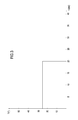
Figure 3 is a Cartesian diagram of the controlled trend of a step of the method according to this invention. - With reference to the accompanying drawings and in particular with reference to
Figures 1 and 2 , the method according to this invention is used for manufacturing ceramic products, in particular, but without limiting its scope, ceramic sanitaryware (such as washbasins, washbasin columns, toilet bowls, bidets and the like) using a liquid mixture known as slip. - This method is obtained on plants such as that shown in
Figures 1 and 2 , which obviously only illustrate the parts of main interest in this description. - This plant, labelled 7 as a whole, comprises at least one
porous mould 1, for example made of porous resin (Figure 1 ), comprising at least twoparts - In the case illustrated, by way of example only and without limiting the scope of the invention, the
mould 1 forms a toilet bowl M. - This
mould 1 has accessory elements, such as ducts for feeding and discharging the slip at predetermined pressures which are connected to a slip tank, and at least one control unit for the product M production cycle which is connected to the slip feed/discharge systems. Said elements are not illustrated, being of the known type and not strictly within the scope of the invention. - In addition, the
plant 7 has a supporting anddrying station 8 for the product M removed from themould 1. Thestation 8 has a base B for supporting the product M. The product is transferred to thestation 8 by suitable robotised elements. - The
station 8 may also comprise additional product M supporting elements, not illustrated in the accompanying drawings, since they do not strictly fall within the scope of the invention. - The method for manufacturing these ceramic products M comprises the steps of:
- filling the
porous mould 1, comprising the twoparts - forming the product M layer by adding slip at a pressure greater than the initial filling pressure;
- emptying excess slip from the
mould 1, lowering the pressure to a value which is normally equal to the ambient pressure; - opening the
parts Figure 1 and arrows F1); - removing the product M from the
mould 1; - product M drying, usually in air and in the
station 8 where the product M was placed after removal from the mould. - After product M removal from the mould, the method according to the invention comprises:
- identification of one or more points P or areas of the product M which have high concentrations of tensions or do not match reference parameters D, S;
- application of a fluid flow F localised around the identified point or points P at a predetermined temperature T and for a predetermined time t, so as to accelerate drying and, therefore, hardening only at that point P or those points P relative to the rest of the surface of the product M.
- Basically, the method hinges on product M "point-by-point" drying based on predetermined parameters, to prevent or reduce the risk of cracks developing in the product M, through rapid acceleration of drying accompanied by a rapid increase in hardness. In particular, one of the reference parameters for the step of identifying points P or areas is the hardness D detected at the relative point P by means of elements 5 (described below).
- Another possible parameter which can be used for the step of identifying points P or areas is a statistical data item S detected which depends on the product M geometry.
- In this latter case, the parameter S is generated from the "history" of each type of product obtained and from its shape which, on each occasion, may have developed cracks at certain points or areas during the drying step and which, therefore, is detected so that it can be treated with the spot drying step.
- The fluid flow F can be generated using compressed air applied, using a
unit 6, around the point or points P detected for a time t which is between 1 and 100 seconds, and at a temperature T at least equal to the ambient temperature. - In particular the application time t may be between 5 and 20 seconds, whilst the application temperature T may be between 15 and 40 degrees (see also graph in
Figure 3 ). - Preferably, the flow may also be applied in sequence, alternating air flow intervals with intervals having no air flow.
- In other terms, the step of applying the fluid flow F is divided into at least two sub-steps whose total duration falls within the total predetermined application time.
- Also according to the invention and as regards the structures implementing the method, the
station 8 comprises theunit 6 for generating a fluid flow F under pressure at a controlled temperature T and which may be activated, usingrespective means 9, for controlled times t. - In other terms, the unit is designed to be positioned close to the at least one or more points P or predetermined areas and to direct the flow F only around those points P or areas.
- In addition, the
plant 7 may comprise anelement 5 for measuring the hardness D of the points P or areas of the product M. - This element may be a "penetrometer" or durometer designed to measure the consistency or hardness of any product M risk areas.
- The
unit 6 for generating the flow of fluid, which, as already indicated, may be compressed air, comprises at least oneterminal 10 connected to aduct 11 for the passage of the pressurised fluid which can be fed from asource 12. - Obviously, there may be two or
more terminals 10 andducts 11 depending on the spot drying requirements. - The terminal 10 and the
duct 11 may be controlled byprogrammable means 9 for switching the fluid flow F on and off according to operating requirements (determined for example by the area to be treated, the outside temperature, the extent of the area to be treated, etc.). - Basically, the
means 9 can be programmed to control the fluid flow F rate, the flow F emission time t and the temperature T of the fluid emitted. - Devices may be used (such as PLCs or programmable logic controllers) to control the generation of a flow output with high pressures for each area of the part to be treated and, obviously, the timing of the flow emitted (for example using valves) and, if necessary, the air temperature (obviously with relative air heating elements upstream).
- A method and a plant designed in this way fulfil the preset aims thanks to the possibility of using a kind of spot drying around the points considered at greatest risk of developing cracks.
- The method allows rapid drying (with more rapid hardening) of the areas without affecting the normal operating times of product production cycles.
- Similarly, the plant does not require significant structural changes, with the simple addition of the flow generating system and if necessary the presence of the system for checking the hardness of points of the product. This reduces the additional cost of the plant against a net improvement in the production of products which significantly reduces the risk of production rejects caused by structural defects.
- The invention described above is susceptible of industrial application and may be modified and adapted in several ways without thereby departing from the scope of the inventive concept. Moreover, all the details of the invention may be substituted by technically equivalent elements.
Claims (12)
- A method for the manufacture of ceramic products, comprises at least the steps of:- filling a porous mould (1), comprising at least two parts (2, 3) which are joined together to form at least one moulding cavity (4), with pressurised slip or fluid mixture;- forming the product (M) layer by adding pressurised slip;- emptying excess slip from the mould (1);- opening the parts (2, 3) of the mould (1);- removing the product (M) from the mould (1);- drying the product (M), the method being characterised in that after the step of removing the product (M) from the mould it comprises:- identification of one or more points (P) or areas of the product (M) which have high concentrations of tensions or do not match reference parameters (D, S);- application of a fluid flow (F) localised around the identified point or points (P) at a predetermined temperature (T) and for a predetermined time (t), so as to accelerate drying and, therefore, hardening only at that point (P) or those points (P) relative to the rest of the surface of the product (M).
- The method according to claim 1, characterised in that one of the reference parameters for the step of identifying the points (P) or areas is the hardness (D) detected at the point (P) by the elements (5).
- Metodo secondo la rivendicazione 1, caratterizzato dal fatto che uno di detti parametri di riferimento per la fase di individuazione di detti punti (P) o zone è un dato statistico (S) rilevato funzione della geometria di detto manufatto (M).
- The method according to claim 1, characterised in that the fluid flow (F) is compressed air applied, using a unit (6), around the point or points (P) detected for a time (t) which is between 1 and 100 seconds, and at a temperature (T) at least equal to the ambient temperature.
- The method according to claim 4, characterised in that the application time (t) is between 5 and 20 seconds.
- The method according to claim 4, characterised in that the application temperature (T) is between 15 and 40 degrees.
- The method according to claim 4, characterised in that the step of applying the fluid flow (F) is divided into at least two sub-steps whose total duration falls within the total predetermined application time.
- A plant for the manufacture of ceramic products according to the method of claims 1 to 7, the plant (7) comprising at least one station (8) for supporting and drying the product (M) removed from the mould (1), the plant being characterised in that it comprises, in the station (8), at least one unit (6) for generating a localised fluid flow (F) under pressure at a controlled temperature (T) and which may be activated, using respective means (9), for controlled times (t), the unit (6) being designed to be positioned close to the at least one or more points (P) or predetermined areas and to direct the flow (F) only around those points (P) or areas.
- The plant according to claim 8, characterised in that it also comprises an element (5) for measuring the hardness (D) of the points (P) or areas of the product (M).
- The plant according to claim 8, characterised in that the unit (6) for generating a flow of fluid comprises at least one terminal (10) connected to a duct (11) for the passage of the pressurised fluid which can be fed from a source (12).
- The plant according to claim 10, characterised in that the terminal (10) and the duct (11) are controlled by programmable means (9) for switching the fluid flow (F) on and off.
- The plant according to claim 10, characterised in that the means (9) can be programmed to control the fluid flow (F) rate, the flow emission time (t) and the temperature (T) of the fluid emitted.
Priority Applications (1)
| Application Number | Priority Date | Filing Date | Title |
|---|---|---|---|
| PL10170337T PL2279840T3 (en) | 2009-07-30 | 2010-07-21 | Method for the manufacture of a ceramic product and plant implementing the method. |
Applications Claiming Priority (1)
| Application Number | Priority Date | Filing Date | Title |
|---|---|---|---|
| ITBO2009A000507A IT1394969B1 (en) | 2009-07-30 | 2009-07-30 | METHOD FOR THE REALIZATION OF A MANUFACTURED MATERIAL IN CERAMIC MATERIAL AND IMPLANTATION OF THIS METHOD. |
Publications (2)
| Publication Number | Publication Date |
|---|---|
| EP2279840A1 true EP2279840A1 (en) | 2011-02-02 |
| EP2279840B1 EP2279840B1 (en) | 2015-09-02 |
Family
ID=41786379
Family Applications (1)
| Application Number | Title | Priority Date | Filing Date |
|---|---|---|---|
| EP10170337.9A Not-in-force EP2279840B1 (en) | 2009-07-30 | 2010-07-21 | Method for the manufacture of a ceramic product and plant implementing the method. |
Country Status (4)
| Country | Link |
|---|---|
| EP (1) | EP2279840B1 (en) |
| ES (1) | ES2554377T3 (en) |
| IT (1) | IT1394969B1 (en) |
| PL (1) | PL2279840T3 (en) |
Cited By (4)
| Publication number | Priority date | Publication date | Assignee | Title |
|---|---|---|---|---|
| CN104972554A (en) * | 2015-07-27 | 2015-10-14 | 周勇 | Automatic spray and maintenance system for T-shaped prefabricated beam |
| CN109195930A (en) * | 2016-04-25 | 2019-01-11 | 赛峰集团 | The method that fibrous texture manufactures composite material parts is injected by the way that slurry will be loaded |
| CN113290678A (en) * | 2021-05-28 | 2021-08-24 | 中国建筑土木建设有限公司 | Intelligent spraying maintenance control method, device, equipment and medium |
| CN113815091A (en) * | 2021-07-30 | 2021-12-21 | 安徽省含山民生瓷业有限责任公司 | Grouting process |
Citations (4)
| Publication number | Priority date | Publication date | Assignee | Title |
|---|---|---|---|---|
| US2767484A (en) * | 1954-11-09 | 1956-10-23 | Gilson Pierre Charles Jean | Device for measuring and regulating the drying of wet products inside a drier |
| DE2301680A1 (en) * | 1973-01-13 | 1974-07-18 | Netzsch Maschinenfabrik | DEVICE FOR DRYING CERAMIC MOLDINGS |
| EP0533406A1 (en) * | 1991-09-18 | 1993-03-24 | Limited Rotajet | Improvements in or relating to drying apparatus |
| DE4323709A1 (en) | 1993-07-15 | 1995-01-19 | Wagner Max Novokeram | Drying method and apparatus |
-
2009
- 2009-07-30 IT ITBO2009A000507A patent/IT1394969B1/en active
-
2010
- 2010-07-21 EP EP10170337.9A patent/EP2279840B1/en not_active Not-in-force
- 2010-07-21 ES ES10170337.9T patent/ES2554377T3/en active Active
- 2010-07-21 PL PL10170337T patent/PL2279840T3/en unknown
Patent Citations (4)
| Publication number | Priority date | Publication date | Assignee | Title |
|---|---|---|---|---|
| US2767484A (en) * | 1954-11-09 | 1956-10-23 | Gilson Pierre Charles Jean | Device for measuring and regulating the drying of wet products inside a drier |
| DE2301680A1 (en) * | 1973-01-13 | 1974-07-18 | Netzsch Maschinenfabrik | DEVICE FOR DRYING CERAMIC MOLDINGS |
| EP0533406A1 (en) * | 1991-09-18 | 1993-03-24 | Limited Rotajet | Improvements in or relating to drying apparatus |
| DE4323709A1 (en) | 1993-07-15 | 1995-01-19 | Wagner Max Novokeram | Drying method and apparatus |
Cited By (5)
| Publication number | Priority date | Publication date | Assignee | Title |
|---|---|---|---|---|
| CN104972554A (en) * | 2015-07-27 | 2015-10-14 | 周勇 | Automatic spray and maintenance system for T-shaped prefabricated beam |
| CN104972554B (en) * | 2015-07-27 | 2017-07-07 | 周勇 | The automatic spray curing system of prefabricated T-shaped beam |
| CN109195930A (en) * | 2016-04-25 | 2019-01-11 | 赛峰集团 | The method that fibrous texture manufactures composite material parts is injected by the way that slurry will be loaded |
| CN113290678A (en) * | 2021-05-28 | 2021-08-24 | 中国建筑土木建设有限公司 | Intelligent spraying maintenance control method, device, equipment and medium |
| CN113815091A (en) * | 2021-07-30 | 2021-12-21 | 安徽省含山民生瓷业有限责任公司 | Grouting process |
Also Published As
| Publication number | Publication date |
|---|---|
| ES2554377T3 (en) | 2015-12-18 |
| ITBO20090507A1 (en) | 2011-01-31 |
| IT1394969B1 (en) | 2012-08-07 |
| PL2279840T3 (en) | 2016-01-29 |
| EP2279840B1 (en) | 2015-09-02 |
Similar Documents
| Publication | Publication Date | Title |
|---|---|---|
| EP2279840B1 (en) | Method for the manufacture of a ceramic product and plant implementing the method. | |
| CN105690550B (en) | Tubular refractory brick mo(u)ldenpress mould, automatic hydraulic press and pressure brickwork skill | |
| CN1964827A (en) | Method for forming high strength mould | |
| TW201347873A (en) | Core sand filling method | |
| JPS5613144A (en) | Installation for mold | |
| KR101689529B1 (en) | Die casting apparatus and die casting method | |
| US20240384468A1 (en) | Method for suctioning fibers from a pulp using a suction device and a suction device | |
| US7556760B2 (en) | Method and apparatus for manufacturing of beads for artificial pearls | |
| US20220062974A1 (en) | Core molding method and core molding device | |
| KR101189761B1 (en) | Apparatus and method for producing clay container | |
| JP6496140B2 (en) | Foam molding equipment | |
| WO2008013456A3 (en) | Method and apparatus for manufacturing products | |
| JP2009023139A (en) | Press molding apparatus | |
| KR101582803B1 (en) | Apparatus for forming precast concrete | |
| JPS5769027A (en) | Method of controlling removing time from mold in rim molding and apparatus therefor | |
| EP2263842B1 (en) | Method and installation for making a ceramic product. | |
| JP3117794B2 (en) | Vent hole cleaning device for foaming mold | |
| CN114438828A (en) | A plant fiber pulp model testing machine | |
| DE69905327D1 (en) | Apparatus for the production of stone moldings for the brick industry | |
| EP2639028B1 (en) | Method and plant for making ceramic ware products | |
| KR200207189Y1 (en) | Pocelain vessel moulding apparatus having an improved ventilation | |
| KR200350568Y1 (en) | Structure of molding part for pulp molding system | |
| RU2258005C1 (en) | Method for molding continuous-length section of foamed polystyrene | |
| JP2003145511A (en) | Method for manufacturing building material and lumber molded product by using lumber of domestic lumber, pine, japan cedar, thinnings or the like as raw material | |
| JPH03155762A (en) | Continuous steaming or boiling device of grain |
Legal Events
| Date | Code | Title | Description |
|---|---|---|---|
| PUAI | Public reference made under article 153(3) epc to a published international application that has entered the european phase |
Free format text: ORIGINAL CODE: 0009012 |
|
| AK | Designated contracting states |
Kind code of ref document: A1 Designated state(s): AL AT BE BG CH CY CZ DE DK EE ES FI FR GB GR HR HU IE IS IT LI LT LU LV MC MK MT NL NO PL PT RO SE SI SK SM TR |
|
| AX | Request for extension of the european patent |
Extension state: BA ME RS |
|
| 17P | Request for examination filed |
Effective date: 20110624 |
|
| RIC1 | Information provided on ipc code assigned before grant |
Ipc: F26B 21/06 20060101ALI20150114BHEP Ipc: B28B 17/00 20060101ALI20150114BHEP Ipc: C04B 33/28 20060101ALI20150114BHEP Ipc: F26B 5/14 20060101ALI20150114BHEP Ipc: B28B 11/24 20060101AFI20150114BHEP Ipc: F26B 21/14 20060101ALI20150114BHEP Ipc: C04B 33/30 20060101ALI20150114BHEP Ipc: F26B 21/00 20060101ALI20150114BHEP |
|
| GRAP | Despatch of communication of intention to grant a patent |
Free format text: ORIGINAL CODE: EPIDOSNIGR1 |
|
| INTG | Intention to grant announced |
Effective date: 20150309 |
|
| GRAS | Grant fee paid |
Free format text: ORIGINAL CODE: EPIDOSNIGR3 |
|
| GRAA | (expected) grant |
Free format text: ORIGINAL CODE: 0009210 |
|
| AK | Designated contracting states |
Kind code of ref document: B1 Designated state(s): AL AT BE BG CH CY CZ DE DK EE ES FI FR GB GR HR HU IE IS IT LI LT LU LV MC MK MT NL NO PL PT RO SE SI SK SM TR |
|
| REG | Reference to a national code |
Ref country code: GB Ref legal event code: FG4D |
|
| REG | Reference to a national code |
Ref country code: AT Ref legal event code: REF Ref document number: 746263 Country of ref document: AT Kind code of ref document: T Effective date: 20150915 Ref country code: CH Ref legal event code: EP |
|
| REG | Reference to a national code |
Ref country code: IE Ref legal event code: FG4D |
|
| REG | Reference to a national code |
Ref country code: DE Ref legal event code: R096 Ref document number: 602010027123 Country of ref document: DE |
|
| REG | Reference to a national code |
Ref country code: ES Ref legal event code: FG2A Ref document number: 2554377 Country of ref document: ES Kind code of ref document: T3 Effective date: 20151218 |
|
| REG | Reference to a national code |
Ref country code: AT Ref legal event code: MK05 Ref document number: 746263 Country of ref document: AT Kind code of ref document: T Effective date: 20150902 |
|
| PG25 | Lapsed in a contracting state [announced via postgrant information from national office to epo] |
Ref country code: LV Free format text: LAPSE BECAUSE OF FAILURE TO SUBMIT A TRANSLATION OF THE DESCRIPTION OR TO PAY THE FEE WITHIN THE PRESCRIBED TIME-LIMIT Effective date: 20150902 Ref country code: FI Free format text: LAPSE BECAUSE OF FAILURE TO SUBMIT A TRANSLATION OF THE DESCRIPTION OR TO PAY THE FEE WITHIN THE PRESCRIBED TIME-LIMIT Effective date: 20150902 Ref country code: GR Free format text: LAPSE BECAUSE OF FAILURE TO SUBMIT A TRANSLATION OF THE DESCRIPTION OR TO PAY THE FEE WITHIN THE PRESCRIBED TIME-LIMIT Effective date: 20151203 Ref country code: LT Free format text: LAPSE BECAUSE OF FAILURE TO SUBMIT A TRANSLATION OF THE DESCRIPTION OR TO PAY THE FEE WITHIN THE PRESCRIBED TIME-LIMIT Effective date: 20150902 Ref country code: NO Free format text: LAPSE BECAUSE OF FAILURE TO SUBMIT A TRANSLATION OF THE DESCRIPTION OR TO PAY THE FEE WITHIN THE PRESCRIBED TIME-LIMIT Effective date: 20151202 |
|
| REG | Reference to a national code |
Ref country code: LT Ref legal event code: MG4D Ref country code: NL Ref legal event code: MP Effective date: 20150902 |
|
| PG25 | Lapsed in a contracting state [announced via postgrant information from national office to epo] |
Ref country code: AT Free format text: LAPSE BECAUSE OF FAILURE TO SUBMIT A TRANSLATION OF THE DESCRIPTION OR TO PAY THE FEE WITHIN THE PRESCRIBED TIME-LIMIT Effective date: 20150902 Ref country code: SE Free format text: LAPSE BECAUSE OF FAILURE TO SUBMIT A TRANSLATION OF THE DESCRIPTION OR TO PAY THE FEE WITHIN THE PRESCRIBED TIME-LIMIT Effective date: 20150902 |
|
| PG25 | Lapsed in a contracting state [announced via postgrant information from national office to epo] |
Ref country code: CZ Free format text: LAPSE BECAUSE OF FAILURE TO SUBMIT A TRANSLATION OF THE DESCRIPTION OR TO PAY THE FEE WITHIN THE PRESCRIBED TIME-LIMIT Effective date: 20150902 Ref country code: IS Free format text: LAPSE BECAUSE OF FAILURE TO SUBMIT A TRANSLATION OF THE DESCRIPTION OR TO PAY THE FEE WITHIN THE PRESCRIBED TIME-LIMIT Effective date: 20160102 Ref country code: NL Free format text: LAPSE BECAUSE OF FAILURE TO SUBMIT A TRANSLATION OF THE DESCRIPTION OR TO PAY THE FEE WITHIN THE PRESCRIBED TIME-LIMIT Effective date: 20150902 Ref country code: EE Free format text: LAPSE BECAUSE OF FAILURE TO SUBMIT A TRANSLATION OF THE DESCRIPTION OR TO PAY THE FEE WITHIN THE PRESCRIBED TIME-LIMIT Effective date: 20150902 Ref country code: SK Free format text: LAPSE BECAUSE OF FAILURE TO SUBMIT A TRANSLATION OF THE DESCRIPTION OR TO PAY THE FEE WITHIN THE PRESCRIBED TIME-LIMIT Effective date: 20150902 |
|
| PG25 | Lapsed in a contracting state [announced via postgrant information from national office to epo] |
Ref country code: RO Free format text: LAPSE BECAUSE OF FAILURE TO SUBMIT A TRANSLATION OF THE DESCRIPTION OR TO PAY THE FEE WITHIN THE PRESCRIBED TIME-LIMIT Effective date: 20150902 Ref country code: PT Free format text: LAPSE BECAUSE OF FAILURE TO SUBMIT A TRANSLATION OF THE DESCRIPTION OR TO PAY THE FEE WITHIN THE PRESCRIBED TIME-LIMIT Effective date: 20160104 |
|
| REG | Reference to a national code |
Ref country code: DE Ref legal event code: R097 Ref document number: 602010027123 Country of ref document: DE |
|
| PLBE | No opposition filed within time limit |
Free format text: ORIGINAL CODE: 0009261 |
|
| STAA | Information on the status of an ep patent application or granted ep patent |
Free format text: STATUS: NO OPPOSITION FILED WITHIN TIME LIMIT |
|
| 26N | No opposition filed |
Effective date: 20160603 |
|
| PG25 | Lapsed in a contracting state [announced via postgrant information from national office to epo] |
Ref country code: SI Free format text: LAPSE BECAUSE OF FAILURE TO SUBMIT A TRANSLATION OF THE DESCRIPTION OR TO PAY THE FEE WITHIN THE PRESCRIBED TIME-LIMIT Effective date: 20150902 Ref country code: DK Free format text: LAPSE BECAUSE OF FAILURE TO SUBMIT A TRANSLATION OF THE DESCRIPTION OR TO PAY THE FEE WITHIN THE PRESCRIBED TIME-LIMIT Effective date: 20150902 |
|
| PG25 | Lapsed in a contracting state [announced via postgrant information from national office to epo] |
Ref country code: BE Free format text: LAPSE BECAUSE OF FAILURE TO SUBMIT A TRANSLATION OF THE DESCRIPTION OR TO PAY THE FEE WITHIN THE PRESCRIBED TIME-LIMIT Effective date: 20150902 |
|
| REG | Reference to a national code |
Ref country code: CH Ref legal event code: PL |
|
| PG25 | Lapsed in a contracting state [announced via postgrant information from national office to epo] |
Ref country code: MC Free format text: LAPSE BECAUSE OF FAILURE TO SUBMIT A TRANSLATION OF THE DESCRIPTION OR TO PAY THE FEE WITHIN THE PRESCRIBED TIME-LIMIT Effective date: 20150902 |
|
| PG25 | Lapsed in a contracting state [announced via postgrant information from national office to epo] |
Ref country code: FR Free format text: LAPSE BECAUSE OF NON-PAYMENT OF DUE FEES Effective date: 20160801 Ref country code: CH Free format text: LAPSE BECAUSE OF NON-PAYMENT OF DUE FEES Effective date: 20160731 Ref country code: LI Free format text: LAPSE BECAUSE OF NON-PAYMENT OF DUE FEES Effective date: 20160731 |
|
| REG | Reference to a national code |
Ref country code: FR Ref legal event code: ST Effective date: 20170331 |
|
| REG | Reference to a national code |
Ref country code: IE Ref legal event code: MM4A |
|
| PG25 | Lapsed in a contracting state [announced via postgrant information from national office to epo] |
Ref country code: IE Free format text: LAPSE BECAUSE OF NON-PAYMENT OF DUE FEES Effective date: 20160721 |
|
| PGFP | Annual fee paid to national office [announced via postgrant information from national office to epo] |
Ref country code: GB Payment date: 20170620 Year of fee payment: 8 |
|
| PG25 | Lapsed in a contracting state [announced via postgrant information from national office to epo] |
Ref country code: LU Free format text: LAPSE BECAUSE OF NON-PAYMENT OF DUE FEES Effective date: 20160721 |
|
| PGFP | Annual fee paid to national office [announced via postgrant information from national office to epo] |
Ref country code: IT Payment date: 20170621 Year of fee payment: 8 Ref country code: PL Payment date: 20170622 Year of fee payment: 8 |
|
| PGFP | Annual fee paid to national office [announced via postgrant information from national office to epo] |
Ref country code: DE Payment date: 20170620 Year of fee payment: 8 Ref country code: ES Payment date: 20170803 Year of fee payment: 8 |
|
| PGFP | Annual fee paid to national office [announced via postgrant information from national office to epo] |
Ref country code: TR Payment date: 20170706 Year of fee payment: 8 |
|
| PG25 | Lapsed in a contracting state [announced via postgrant information from national office to epo] |
Ref country code: SM Free format text: LAPSE BECAUSE OF FAILURE TO SUBMIT A TRANSLATION OF THE DESCRIPTION OR TO PAY THE FEE WITHIN THE PRESCRIBED TIME-LIMIT Effective date: 20150902 Ref country code: HU Free format text: LAPSE BECAUSE OF FAILURE TO SUBMIT A TRANSLATION OF THE DESCRIPTION OR TO PAY THE FEE WITHIN THE PRESCRIBED TIME-LIMIT; INVALID AB INITIO Effective date: 20100721 Ref country code: CY Free format text: LAPSE BECAUSE OF FAILURE TO SUBMIT A TRANSLATION OF THE DESCRIPTION OR TO PAY THE FEE WITHIN THE PRESCRIBED TIME-LIMIT Effective date: 20150902 |
|
| PG25 | Lapsed in a contracting state [announced via postgrant information from national office to epo] |
Ref country code: HR Free format text: LAPSE BECAUSE OF FAILURE TO SUBMIT A TRANSLATION OF THE DESCRIPTION OR TO PAY THE FEE WITHIN THE PRESCRIBED TIME-LIMIT Effective date: 20150902 Ref country code: MK Free format text: LAPSE BECAUSE OF FAILURE TO SUBMIT A TRANSLATION OF THE DESCRIPTION OR TO PAY THE FEE WITHIN THE PRESCRIBED TIME-LIMIT Effective date: 20150902 Ref country code: MT Free format text: LAPSE BECAUSE OF NON-PAYMENT OF DUE FEES Effective date: 20160731 |
|
| PG25 | Lapsed in a contracting state [announced via postgrant information from national office to epo] |
Ref country code: BG Free format text: LAPSE BECAUSE OF FAILURE TO SUBMIT A TRANSLATION OF THE DESCRIPTION OR TO PAY THE FEE WITHIN THE PRESCRIBED TIME-LIMIT Effective date: 20150902 |
|
| PG25 | Lapsed in a contracting state [announced via postgrant information from national office to epo] |
Ref country code: AL Free format text: LAPSE BECAUSE OF FAILURE TO SUBMIT A TRANSLATION OF THE DESCRIPTION OR TO PAY THE FEE WITHIN THE PRESCRIBED TIME-LIMIT Effective date: 20150902 |
|
| REG | Reference to a national code |
Ref country code: DE Ref legal event code: R119 Ref document number: 602010027123 Country of ref document: DE |
|
| GBPC | Gb: european patent ceased through non-payment of renewal fee |
Effective date: 20180721 |
|
| PG25 | Lapsed in a contracting state [announced via postgrant information from national office to epo] |
Ref country code: DE Free format text: LAPSE BECAUSE OF NON-PAYMENT OF DUE FEES Effective date: 20190201 Ref country code: GB Free format text: LAPSE BECAUSE OF NON-PAYMENT OF DUE FEES Effective date: 20180721 |
|
| PG25 | Lapsed in a contracting state [announced via postgrant information from national office to epo] |
Ref country code: IT Free format text: LAPSE BECAUSE OF NON-PAYMENT OF DUE FEES Effective date: 20180721 |
|
| REG | Reference to a national code |
Ref country code: ES Ref legal event code: FD2A Effective date: 20190917 |
|
| PG25 | Lapsed in a contracting state [announced via postgrant information from national office to epo] |
Ref country code: ES Free format text: LAPSE BECAUSE OF NON-PAYMENT OF DUE FEES Effective date: 20180722 |
|
| PG25 | Lapsed in a contracting state [announced via postgrant information from national office to epo] |
Ref country code: PL Free format text: LAPSE BECAUSE OF NON-PAYMENT OF DUE FEES Effective date: 20180721 |
|
| PG25 | Lapsed in a contracting state [announced via postgrant information from national office to epo] |
Ref country code: TR Free format text: LAPSE BECAUSE OF NON-PAYMENT OF DUE FEES Effective date: 20180721 |