EP2278231A2 - Klimaanlage - Google Patents
Klimaanlage Download PDFInfo
- Publication number
- EP2278231A2 EP2278231A2 EP10006404A EP10006404A EP2278231A2 EP 2278231 A2 EP2278231 A2 EP 2278231A2 EP 10006404 A EP10006404 A EP 10006404A EP 10006404 A EP10006404 A EP 10006404A EP 2278231 A2 EP2278231 A2 EP 2278231A2
- Authority
- EP
- European Patent Office
- Prior art keywords
- heat exchanger
- cavity
- space
- air conditioning
- wall
- Prior art date
- Legal status (The legal status is an assumption and is not a legal conclusion. Google has not performed a legal analysis and makes no representation as to the accuracy of the status listed.)
- Granted
Links
Images


Classifications
-
- F—MECHANICAL ENGINEERING; LIGHTING; HEATING; WEAPONS; BLASTING
- F24—HEATING; RANGES; VENTILATING
- F24F—AIR-CONDITIONING; AIR-HUMIDIFICATION; VENTILATION; USE OF AIR CURRENTS FOR SCREENING
- F24F3/00—Air-conditioning systems in which conditioned primary air is supplied from one or more central stations to distributing units in the rooms or spaces where it may receive secondary treatment; Apparatus specially designed for such systems
- F24F3/044—Systems in which all treatment is given in the central station, i.e. all-air systems
-
- F—MECHANICAL ENGINEERING; LIGHTING; HEATING; WEAPONS; BLASTING
- F24—HEATING; RANGES; VENTILATING
- F24F—AIR-CONDITIONING; AIR-HUMIDIFICATION; VENTILATION; USE OF AIR CURRENTS FOR SCREENING
- F24F11/00—Control or safety arrangements
- F24F11/0001—Control or safety arrangements for ventilation
-
- H—ELECTRICITY
- H05—ELECTRIC TECHNIQUES NOT OTHERWISE PROVIDED FOR
- H05K—PRINTED CIRCUITS; CASINGS OR CONSTRUCTIONAL DETAILS OF ELECTRIC APPARATUS; MANUFACTURE OF ASSEMBLAGES OF ELECTRICAL COMPONENTS
- H05K7/00—Constructional details common to different types of electric apparatus
- H05K7/20—Modifications to facilitate cooling, ventilating, or heating
- H05K7/20709—Modifications to facilitate cooling, ventilating, or heating for server racks or cabinets; for data centers, e.g. 19-inch computer racks
- H05K7/20718—Forced ventilation of a gaseous coolant
- H05K7/20745—Forced ventilation of a gaseous coolant within rooms for removing heat from cabinets, e.g. by air conditioning device
-
- F—MECHANICAL ENGINEERING; LIGHTING; HEATING; WEAPONS; BLASTING
- F24—HEATING; RANGES; VENTILATING
- F24F—AIR-CONDITIONING; AIR-HUMIDIFICATION; VENTILATION; USE OF AIR CURRENTS FOR SCREENING
- F24F2221/00—Details or features not otherwise provided for
- F24F2221/40—HVAC with raised floors
-
- Y—GENERAL TAGGING OF NEW TECHNOLOGICAL DEVELOPMENTS; GENERAL TAGGING OF CROSS-SECTIONAL TECHNOLOGIES SPANNING OVER SEVERAL SECTIONS OF THE IPC; TECHNICAL SUBJECTS COVERED BY FORMER USPC CROSS-REFERENCE ART COLLECTIONS [XRACs] AND DIGESTS
- Y02—TECHNOLOGIES OR APPLICATIONS FOR MITIGATION OR ADAPTATION AGAINST CLIMATE CHANGE
- Y02B—CLIMATE CHANGE MITIGATION TECHNOLOGIES RELATED TO BUILDINGS, e.g. HOUSING, HOUSE APPLIANCES OR RELATED END-USER APPLICATIONS
- Y02B30/00—Energy efficient heating, ventilation or air conditioning [HVAC]
- Y02B30/70—Efficient control or regulation technologies, e.g. for control of refrigerant flow, motor or heating
Definitions
- the invention relates to an air conditioner according to the preamble of claim 1.
- Such air conditioning is out of the DE 100 48 877 C2 known.
- an air conditioner for placement in a room having a floor and an underlying cavity.
- the air conditioner extends with a housing through the bottom and contains above the bottom of a cooling device in the form of a heat exchanger for cooling heated room air and arranged below the bottom fan means for discharging the cooled air.
- the fan means includes a fan wheel arranged so that the cooled air exits the fan means radially to the fan axis and substantially parallel to the floor.
- the air conditioners used should have the highest possible cooling power density, ie a high cooling capacity, with the smallest possible footprint.
- heat exchangers are used, which can work with relatively high flow temperatures, with flow / return temperature ratios of 10/15 ° C or 16/22 ° C are sought.
- the EP 0 741 269 A2 used to cool a room with a arranged below the floor cavity an air conditioner with heat exchanger and fan, which is located above the ground. All devices, so the devices to be cooled and the air conditioner, there have a flow connection to the cavity below the floor.
- the air conditioner with heat exchanger and fan is arranged within the space to be cooled, with a cold generator can be arranged outside the space to be cooled. Nevertheless, the arranged in the space to be cooled part of the air conditioner takes up a considerable footprint, which is not for equipment such as computers, usable.
- the object of the invention is to improve the air conditioning of the type mentioned in that a high cooling capacity is achieved with little need for footprint in the space to be cooled.
- the air conditioning should be flexible adaptable to different rooms.
- the basic idea of the invention is to design the heat exchanger without a housing and to form it over such a large area that it forms a substantial portion of the area of a space boundary.
- the heat exchanger and the fan device are separated from each other and can be placed independently, so that a great flexibility in the arrangement of the components of the air conditioning is given with respect to the room.
- the heat exchanger is placed in parallel at close distance to at least one wall of the room. This results in between the corresponding wall of the room and the heat exchanger, a cavity which communicates with the arranged below the bottom cavity in flow communication.
- the surface of the heat exchanger corresponds to the area of the adjacent wall of the room, so that the heat exchanger practically forms a complete space boundary.
- the caseless heat exchanger can also be arranged "over the corner", i. be arranged parallel to two or more walls of the room. Also, the heat exchanger can be arranged with a corresponding room divider wall as "island solution" in space.
- the heat exchanger can cover only a part of a wall of the room.
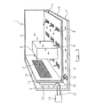
- Fig. 1 shows a schematic perspective cut top view of a room to be air-conditioned 1, of which a first side wall 2 and a second Side wall 3 can be seen.
- the space has a bottom 4, below which a cavity 5 is located.
- the bottom 4 is supported by a plurality of support elements 6 with respect to a lower wall 7.
- the bottom 4 has a plurality of openings 8 through which the space 1 is in fluid communication with the cavity 5 for an air flow indicated by arrows.
- the openings 8 are covered by gratings.
- a heat exchanger 10 is arranged at a distance from the first side wall 2, so that a second cavity 11 is formed between the first side wall 2 and the back of the heat exchanger 10 facing away from the space 1.
- the heat exchanger 10 is here connected via pipes 12 and 13 with a cooling device 14, which is located outside of the room 1.
- a cooling medium e.g. Water
- the flow of the cooling medium can be regulated by the heat exchanger 10, which can be done under the control of a thermostat, not shown, located in the room 1.
- a fan device 16 is arranged in the first cavity 5.
- it is a housing-less centrifugal fan, which generates a radially directed to its axis of rotation air flow.
- the fan device 16 may be arranged according to an embodiment, not shown, in the second cavity 11, ie above the bottom 4.
- the heat exchanger 10 covers in the embodiment of Fig. 1 Due to its large area, it provides a large cooling capacity and can thus be operated with a small temperature difference between flow and return temperature of the cooling medium.
- the fan device 16 By the fan device 16, an overpressure is generated in the first cavity 5, which causes an air flow along the arrows.
- the flow in the first cavity is substantially parallel and exits vertically from the openings 8 from the bottom 4 into the space 1. There it runs back towards the heat exchanger 10 and cools the objects 9, which usually have their own fans in computers or cabinets, which direct the air through the interior of the articles 9. From there, the flow passes to and through the heat exchanger 10 into the second cavity 11, where it flows substantially vertically down to the fan means 16.
- the caseless heat exchanger 10 is independent of the fan device 16 in terms of its arrangement or position, so that depending on the structural conditions of the room results in a high flexibility.
- the heat exchanger and the fan device can thus at any time in terms of their size and quantity Needs adapted or later retrofitted.
- a plurality of fan means may be arranged to produce a sufficient and uniform flow.
- guide walls or partition walls 17 and 18 may be arranged, which form separate flow paths and each associated with its own fan device.
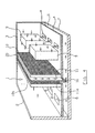
- Fig. 2 is different from that of Fig. 1 in that the heat exchanger 10 is arranged "over the corner", that is arranged parallel to the first side wall 2 with one element 10 and with another element 10a parallel to the second side wall 3, wherein additionally the element 10a lying parallel to the second side wall 3 only in the Upper region of the second side wall 3 is arranged, while in the lower region a sealing plate 19 is arranged.
- the area covered by the heat exchanger 10 is smaller than the area of the first side wall 2, the heat exchanger 10 is then inserted into a sealing plate 19, which in turn is parallel and spaced from the first side wall 2 and thus together with the heat exchanger 10 and Side wall 2 forms the second cavity 11.
- the heat exchanger 10 and the fan means 16 are independent of each other and the heat exchanger 10 is without housing.
- the area covered here by the heat exchanger 10 is about 50% of the area of the side wall 2.
- Fig. 4 shows an embodiment in which the heat exchangers 10 and 10a are used together with a partition wall 20 as a room divider.
- a partition wall 20 as a room divider.
- two parallel cavities 11 and 11a separated by the dividing wall 20 are formed, each communicating with the first cavity 5 in fluid communication.
- a common fan means 16 is disposed below the partition wall 20 and blows the air coming vertically from above from the cavities 11 and 11a radially to its vertical axis of rotation to both sides.
- piping to the two heat exchangers 10 and 10a are expediently in the lower cavity 5 to the outside to a cooling unit, also not shown (see Fig. 1 ) guided.
- the heat exchangers 10 and 10a can cover both the entire surface of one of the side walls such as the side wall 2 or they can also according to the variant of Fig. 3 cover only part of the corresponding wall.
- the invention thus provides a highly effective and flexible the structural conditions of a room adaptable air conditioning with a simple structure. Due to the large effective area of the heat exchanger can be used with low temperature differences between flow and return temperature of the cooling medium for the heat exchanger. Also, fan devices with low energy requirements can be used and the flow rate of air moving in space can be kept low, so that this air conditioner can also be used in rooms where people work without being affected by "drafts".
- cooling device 14 As a cooling device 14 ( Fig. 1 ) All known cooling devices in question, such as a heat exchanger, which is placed outdoors and the local ambient air for cooling the coming out of the heat exchanger 10 of the room 1 medium such as water or other cooling liquid cools.
- a heat exchanger which is placed outdoors and the local ambient air for cooling the coming out of the heat exchanger 10 of the room 1 medium such as water or other cooling liquid cools.
- One possibility is to place a corresponding heat exchanger in a well, a river or other waters.
- a heat exchanger which is sprayed with a liquid, such as water and dissipates heat by evaporative cooling.
- compressor cooling units or cooling units with Peltier elements can also be used.
Abstract
Description
- Die Erfindung bezieht sich auf eine Klimaanlage gemäß dem Oberbegriff des Patentanspruches 1.
- Eine solche Klimaanlage ist aus der
DE 100 48 877 C2 bekannt. Dort ist ein Klimagerät zur Anordnung in einem Raum beschrieben, der einen Boden und einen darunterliegenden Hohlraum aufweist. Das Klimagerät erstreckt sich mit einem Gehäuse durch den Boden hindurch und enthält oberhalb des Bodens eine Kühleinrichtung in Form eines Wärmetauschers zum Abkühlen erwärmter Raumluft und eine unterhalb des Bodens angeordnete Ventilatoreinrichtung zum Abführen der abgekühlten Luft. Die Ventilatoreinrichtung enthält ein Ventilatorrad, daß so angeordnet ist, daß die abgekühlte Luft radial zur Ventilatorachse und im wesentlichen parallel zum Boden aus der Ventilatoreinrichtung austritt. - Durch die Zunahme elektrischer und elektronischer Geräte, insbesondere Computer, fallen in Büros, Serverräumen und Rechenzentren erhebliche Energiemengen an Abwärme an, die durch leistungsfähige Kühl- bzw. Klimageräte abgeführt werden muß, um die Computer vor Überhitzung zu schützen. Die verwendeten Klimageräte sollen eine möglichst hohe Kühlleistungsdichte, d.h. eine hohe Kühlleistung, bei möglichst kleiner Standfläche haben. Hierfür werden Wärmetauscher eingesetzt, die mit relativ hohen Vorlauftemperaturen arbeiten können, wobei Vorlauf-/Rücklauftemperaturverhältnisse von 10/15°C oder 16/22°C angestrebt werden.
- Die
EP 0 741 269 A2 verwendet zur Kühlung eines Raumes mit einem unterhalb des Bodens angeordneten Hohlraum ein Klimagerät mit Wärmetauscher und Ventilator, das oberhalb des Bodens angeordnet ist. Alle Geräte, also die zu kühlenden Geräte und das Klimagerät, haben dort eine Strömungsverbindung zu dem Hohlraum unterhalb des Bodens. Das Klimagerät mit Wärmetauscher und Ventilator ist innerhalb des zu kühlenden Raumes angeordnet, wobei ein Kälteerzeuger außerhalb des zu kühlenden Raumes angeordnet sein kann. Gleichwohl nimmt der in dem zu kühlenden Raum angeordnete Teil des Klimagerätes eine beträchtliche Stellfläche in Anspruch, die nicht für Geräte, wie z.B. Computer, nutzbar ist. - Ähnliche Einrichtungen mit Wärmetauscher und Ventilator sind auch aus der
DE 10 2007 007 928 A1 ,DE 20 2007 002 361 U1 undDE 20 2008 010 063 U1 bekannt. - Aufgabe der Erfindung ist es, die Klimaanlage der eingangs genannten Art dahingehend zu verbessern, daß eine hohe Kühlleistung bei geringem Bedarf an Stellfläche in dem zu kühlenden Raum erreicht wird. Weiter soll die Klimaanlage flexibel an unterschiedliche Räume anpaßbar sein.
- Diese Aufgabe wird durch die im Patentanspruch 1 angegebenen Merkmale gelöst. Vorteilhafte Ausgestaltungen und Weiterbildungen der Erfindung sind den Unteransprüchen zu entnehmen.
- Die Grundidee der Erfindung besteht darin, den Wärmetauscher gehäuselos auszugestalten und ihn so großflächig auszubilden, daß er einen wesentlichen Anteil der Fläche einer Raumbegrenzung bildet. Der Wärmetauscher und die Ventilatoreinrichtung sind dabei voneinander getrennt und können unabhängig voneinander plaziert werden, so daß eine große Flexibilität hinsichtlich der Anordnung der Komponenten der Klimaanlage bezüglich des Raumes gegeben ist. Der Wärmetauscher wird parallel in engem Abstand zu mindestens einer Wand des Raumes aufgestellt. Damit ergibt sich zwischen der entsprechenden Wand des Raumes und dem Wärmetauscher ein Hohlraum, der mit dem unterhalb des Bodens angeordneten Hohlraum in Strömungsverbindung steht.
- Bei einem Ausführungsbeispiel der Erfindung entspricht die Fläche des Wärmetauschers der Fläche der benachbarten Wand des Raumes, so daß der Wärmetauscher praktisch eine vollständige Raumbegrenzung bildet. Durch diese großflächige Ausgestaltung des Wärmetauschers wird eine hohe Kühlleistung erreicht. Auch entstehen durch den großflächigen Wärmetauscher wesentlich reduzierte Druckverluste hinsichtlich der Luftströmung durch den Wärmetauscher. Man kann daher kleinere Lüfter mit geringerem Energieverbrauch verwenden, was auch die Geräuschentwicklung reduziert. Andererseits kann man mit herkömmlich groß dimensionierten Lüftern eine höhere Kühlleistung erreichen.
- Der gehäuselose Wärmetauscher kann auch "über Eck" angeordnet werden, d.h. parallel zu zwei oder mehr Wänden des Raumes angeordnet sein. Auch kann der Wärmetauscher mit entsprechender Raumteilerwand als "Insellösung" im Raum angeordnet sein.
- Je nach zu erbringender Kühlleistung kann der Wärmetauscher auch nur einen Teil einer Wand des Raumes abdecken.
- Im folgenden wird die Erfindung anhand von Ausführungsbeispielen im Zusammenhang mit der Zeichnung ausführlicher erläutert. Es zeigt:
- Fig. 1
- eine perspektivische Prinzipdarstellung ei- nes Raumes mit Klimaanlage nach der Erfin- dung;
- Fig. 2
- ein Ausführungsbeispiel der Erfindung, bei der der Wärmetauscher über Eck angeordnet ist;
- Fig. 3
- ein Ausführungsbeispiel der Erfindung, bei der der Wärmetauscher nur einen Teil einer Wand des Raumes abdeckt;
- Fig. 4
- eine Klimaanlage nach der Erfindung, bei der der Wärmetauscher in der Mitte des Raumes angeordnet ist.
-
Fig. 1 zeigt in schematischer perspektivischer geschnittener Draufsicht einen zu klimatisierenden Raum 1, von dem eine erste Seitenwand 2 und eine zweite Seitenwand 3 zu sehen sind. Der Raum hat einen Boden 4, unterhalb dessen sich ein Hohlraum 5 befindet. Der Boden 4 ist über mehrere Trägerelemente 6 gegenüber einer unteren Wand 7 abgestützt. Der Boden 4 hat eine Vielzahl von Öffnungen 8, über die der Raum 1 mit dem Hohlraum 5 in Strömungsverbindung für eine Luftströmung steht, die durch Pfeile angedeutet ist. Die Öffnungen 8 sind durch Gitterroste abgedeckt. - In dem Raum befinden sich zu kühlende Gegenstände 9, die beispielsweise Computer oder Schaltschränke sind, die Wärme entwickeln, welche abzuführen ist.
- Parallel zur ersten Seitenwand 2 ist ein Wärmetauscher 10 in einem Abstand zur ersten Seitenwand 2 angeordnet, so daß sich zwischen der ersten Seitenwand 2 und der dem Raum 1 abgewandten Rückseite des Wärmetauschers 10 ein zweiter Hohlraum 11 bildet.
- Der Wärmetauscher 10 ist hier über Rohrleitungen 12 und 13 mit einer Kühleinrichtung 14 verbunden, die sich außerhalb des Raumes 1 befindet. Über diese Rohrleitungen wird ein Kühlmedium, wie z.B. Wasser, zu dem Wärmetauscher 10 geleitet und von diesem abgeführt. Über ein Regelventil 15 kann der Durchfluß des Kühlmediums durch den Wärmetauscher 10 geregelt werden, was unter Steuerung eines nicht dargestellten, im Raum 1 befindlichen Thermostat erfolgen kann.
- Im ersten Hohlraum 5 ist eine Ventilatoreinrichtung 16 angeordnet. Vorzugsweise handelt es sich um einen gehäuselosen Radialventilator, der eine radial zu seiner Drehachse gerichtete Luftströmung erzeugt. Die Ventilatoreinrichtung 16 kann nach einem nicht dargestellten Ausführungsbeispiel auch in den zweiten Hohlraum 11, also oberhalb des Bodens 4 angeordnet sein.
- Der Wärmetauscher 10 deckt im Ausführungsbeispiel der
Fig. 1 im wesentlichen die gesamte erste Seitenwand 2 ab und bildet damit eine Begrenzungswand des nutzbaren Raumes 1. Aufgrund seiner großen Fläche erbringt er eine große Kühlleistung und kann damit mit einer geringen Temperaturdifferenz zwischen Vorlauf- und Rücklauftemperatur des Kühlmediums betrieben werden. - Durch die Ventilatoreinrichtung 16 wird im ersten Hohlraum 5 ein Überdruck erzeugt, der eine Luftströmung entlang der Pfeile bewirkt. Die Strömung verläuft im ersten Hohlraum im wesentlichen parallel und tritt vertikal aus den Öffnungen 8 aus dem Boden 4 in den Raum 1 aus. Dort läuft sie zurück in Richtung zu dem Wärmetauscher 10 und kühlt die Gegenstände 9, die üblicherweise bei Computern oder Schaltschränken noch eigene Lüfter haben, die die Luft durch das Innere der Gegenstände 9 leiten. Von dort gelangt die Strömung zu dem Wärmetauscher 10 und durch diesen hindurch in den zweiten Hohlraum 11, wo sie im wesentlichen vertikal nach unten zu der Ventilatoreinrichtung 16 strömt.
- Der gehäuselose Wärmetauscher 10 ist hinsichtlich seiner Anordnung bzw. Lage unabhängig von der Ventilatoreinrichtung 16, so daß sich je nach baulichen Gegebenheiten des Raumes eine hohe Flexibilität ergibt. Der Wärmetauscher und die Ventilatoreinrichtung können damit hinsichtlich ihrer Größe und Menge jederzeit den Bedürfnissen angepaßt oder auch später nachgerüstet werden.
- Selbstverständlich können im Hohlraum 5 oder im Hohlraum 11 auch mehrere Ventilatoreinrichtungen angeordnet sein, um eine ausreichende und gleichmäßige Strömung zu erzeugen. Dabei können in den beiden Hohlräumen 5 und 11 auch Leit- oder Trennwände 17 und 18 angeordnet sein, die getrennte Strömungswege bilden und denen jeweils eine eigene Ventilatoreinrichtung zugeordnet ist.
- Das Ausführungsbeispiel der
Fig. 2 unterscheidet sich von dem derFig. 1 dadurch, daß der Wärmetauscher 10 "über Eck" angeordnet ist, d.h. mit einem Element 10 parallel zur ersten Seitenwand 2 und mit einem anderen Element 10a parallel zur zweiten Seitenwand 3 angeordnet ist, wobei zusätzlich das parallel zur zweiten Seitenwand 3 liegende Element 10a nur im oberen Bereich der zweiten Seitenwand 3 angeordnet ist, während im unteren Bereich eine abdichtende Platte 19 angeordnet ist. - Im Ausführungsbeispiel der
Fig. 3 ist die von dem Wärmetauscher 10 abgedeckte Fläche kleiner als die Fläche der ersten Seitenwand 2, wobei der Wärmetauscher 10 dann in eine abdichtende Platte 19 eingesetzt ist, die ihrerseits parallel und im Abstand zur ersten Seitenwand 2 liegt und damit zusammen mit dem Wärmetauscher 10 und der Seitenwand 2 den zweiten Hohlraum 11 bildet. Auch hier sind aber der Wärmetauscher 10 und die Ventilatoreinrichtung 16 unabhängig voneinander und der Wärmetauscher 10 ist gehäuselos. Generell ist aber festzuhalten, daß die hier von dem Wärmetauscher 10 abgedeckte Fläche etwa 50% der Fläche der Seitenwand 2 beträgt. -
Fig. 4 zeigt ein Ausführungsbeispiel, bei dem Wärmetauscher 10 und 10a zusammen mit einer Trennwand 20 als Raumteiler verwendet werden. Hierbei werden zwei parallele durch die Trennwand 20 getrennte Hohlräume 11 und 11a gebildet, die jeweils mit dem ersten Hohlraum 5 in Strömungsverbindung stehen. Eine gemeinsame Ventilatoreinrichtung 16 ist unterhalb der Trennwand 20 angeordnet und bläst die vertikal von oben aus den Hohlräumen 11 und 11a kommende Luft radial zu ihrer vertikalen Drehachse nach beiden Seiten. - Nicht dargestellte Rohrleitungen zu den beiden Wärmetauschern 10 und 10a werden hier zweckmäßiger Weise im unteren Hohlraum 5 nach außen zu einem ebenfalls nicht dargestellten Kühlaggregat (vgl. 14 in
Fig. 1 ) geführt. - Auch bei dieser Variante können die Wärmetauscher 10 und 10a sowohl die gesamte Fläche einer der Seitenwände wie z.B. der Seitenwand 2 abdecken oder sie können auch entsprechend der Variante der
Fig. 3 nur einen Teil der entsprechenden Wand abdecken. - Selbstverständlich können auch hier in den Hohlräumen 5, 11 und 11a Trennwände entsprechend den Trennwänden 17 und 18 der
Fig. 1 angeordnet sein, wobei dann auch mehrere Ventilatoreinrichtungen einzusetzen sind. Zusammengefaßt schafft die Erfindung also eine hochwirksame und flexibel den baulichen Gegebenheiten eines Raumes anpaßbare Klimaanlage mit einfachem Aufbau. Aufgrund der großen wirksamen Fläche der Wärmetauscher kann mit geringen Temperaturdifferenzen zwischen Vorlauf- und Rücklauftemperatur des Kühlmediums für die Wärmetauscher gearbeitet werden. Auch können Ventilatoreinrichtungen mit niedrigem Energiebedarf eingesetzt werden und die Strömungsgeschwindigkeit der im Raum bewegten Luft kann gering gehalten werden, so daß diese Klimaanlage auch in Räumen eingesetzt werden kann, in denen Personen arbeiten, ohne daß diese durch "Zugluft" beeinträchtigt werden. - Als Kühleinrichtung 14 (
Fig. 1 ) kommen alle bekannten Kühleinrichtungen in Frage, wie z.B. ein Wärmetauscher, der im Freien aufgestellt ist und die dortige Umgebungsluft zur Kühlung des aus dem Wärmetauscher 10 des Raumes 1 kommende Medium wie Wasser oder sonstige Kühlflüssigkeit abkühlt. Eine Möglichkeit besteht darin, einen entsprechenden Wärmetauscher in einen Brunnen, einen Fluß oder ein sonstiges Gewässer zu setzen. Denkbar ist auch ein Wärmetauscher, der mit einer Flüssigkeit, wie Wasser besprüht wird und durch Verdunstungskälte Wärme abführt. Je nach Umweltbedingungen können auch Kompressor-Kühlaggregate oder Kühlaggregate mit Peltierelementen verwendet werden. - Abschließend sei darauf hingewiesen, daß die in den einzelnen Ausführungsbeispielen beschriebenen Merkmale auch miteinander kombiniert werden können. Nur als Beispiel sei erwähnt, daß die in
Fig. 4 gezeigte "Insellösung" auch mit der inFig. 2 gezeigten Ecklösung kombiniert werden kann oder die inFig. 1 beschriebene Lösung mit den Trennwänden 17 und 18 auch bei den Ausführungsbeispielen derFig. 2 ,3 und4 angewandt werden kann.
Claims (11)
- Klimaanlage zur Anordnung in einem Raum, der einen Boden (4) mit Öffnungen (8) und einen darunter liegenden Hohlraum (5) aufweist, mit einem Oberhalb des Bodens (4) angeordneten Wärmetauscher (10) und eine Ventilatoreinrichtung (16), die vom Wärmetauscher abfließende Kühlluft durch den Hohlraum (5) zu den Öffnungen (8) fördert, dadurch gekennzeichnet, daß der Wärmetauscher (10) gehäuselos ist und mindestens einen Teilbereich einer Begrenzungswand des Raumes (1) bildet.
- Klimaanlage nach Anspruch 1, dadurch gekennzeichnet, daß der Wärmetauscher (10) unter Bildung eines zweiten Hohlraumes (11) parallel zu einer Wand (2) des Raumes (1) angeordnet ist und daß der zweite Hohlraum (11) mit dem unterhalb des Bodens (4) angeordneten Hohlraum (5) in Strömungsverbindung steht.
- Klimaanlage nach Anspruch 2, dadurch gekennzeichnet, daß die Ventilatoreinrichtung (16) im unterhalb des Bodens (4) angeordneten Hohlraum (5) angeordnet ist.
- Klimaanlage nach Anspruch 2, dadurch gekennzeichnet, daß die Ventilatoreinrichtung (16) im zweiten Hohlraum (11) angeordnet ist.
- Klimaanlage nach einem der Ansprüche 1 oder 4,
dadurch gekennzeichnet, daß der Wärmetauscher (10) und die Ventilatoreinrichtung (16) als separate Bauteile unabhängig voneinander plazierbar sind. - Klimaanlage nach einem der Ansprüche 1 bis 5, dadurch gekennzeichnet, daß der Wärmetauscher (10) mindestens die Hälfte der Fläche der benachbarten Wand (2) des Raumes (1) abdeckt.
- Klimaanlage nach einem der Ansprüche 1 bis 6, dadurch gekennzeichnet, daß der Wärmetauscher (10, 10a) gegenüberliegend zu zwei aneinander angrenzenden Wänden (2, 3) des Raumes (1) unter Bildung von zwei Hohlräumen (11, 11a) angeordnet ist.
- Klimaanlage nach Anspruch 1, dadurch gekennzeichnet, daß der Wärmetauscher (10, 10a) als Raumteiler im Raum (1) angeordnet ist.
- Klimaanlage nach Anspruch 8, dadurch gekennzeichnet, daß zwei Wärmetauscher (10, 10a) und eine zwischen diesen angeordnete Trennwand (20) unter Bildung von zwei Hohlräumen (11, 11a) im Raum angeordnet sind, wobei beide Hohlräume (11, 11a) mit dem unterhalb des Bodens (4a) angeordneten Hohlraum (5) in Strömungsverbindung stehen.
- Klimaanlage nach einem der Ansprüche 1 bis 9, dadurch gekennzeichnet, daß der bzw. die Wärmetauscher (10; 10a) senkrecht im Raum (1) angeordnet sind.
- Klimaanlage nach einem der Ansprüche 1 bis 10, dadurch gekennzeichnet, daß der unterhalb des Bodens (4) angeordnete Hohlraum (5) durch mindestens eine Trennwand (18) in mindestens zwei Teilhohlräume unterteilt ist, daß der zwischen der Wand (2) des Raumes (1) und dem Wärmetauscher (10) angeordnete Hohlraum (11) ebenfalls durch eine Trennwand (17) in mindestens zwei Teilhohlräume unterteilt ist und daß die jeweiligen Teilhohlräume unterhalb des Bodens (4) mit den genannten Teilhohlräumen zwischen der Wand (2) und dem Wärmetauscher (10) jeweils miteinander in Strömungsverbindung stehen.
Priority Applications (1)
| Application Number | Priority Date | Filing Date | Title |
|---|---|---|---|
| PL10006404T PL2278231T3 (pl) | 2009-06-22 | 2010-06-21 | Układ instalacji klimatyzacji |
Applications Claiming Priority (1)
| Application Number | Priority Date | Filing Date | Title |
|---|---|---|---|
| DE102009030114A DE102009030114B4 (de) | 2009-06-22 | 2009-06-22 | Klimaanlage |
Publications (3)
| Publication Number | Publication Date |
|---|---|
| EP2278231A2 true EP2278231A2 (de) | 2011-01-26 |
| EP2278231A3 EP2278231A3 (de) | 2016-11-02 |
| EP2278231B1 EP2278231B1 (de) | 2017-11-08 |
Family
ID=42749233
Family Applications (1)
| Application Number | Title | Priority Date | Filing Date |
|---|---|---|---|
| EP10006404.7A Active EP2278231B1 (de) | 2009-06-22 | 2010-06-21 | Klimaanlage |
Country Status (4)
| Country | Link |
|---|---|
| EP (1) | EP2278231B1 (de) |
| DE (2) | DE202009014942U1 (de) |
| NO (1) | NO2278231T3 (de) |
| PL (1) | PL2278231T3 (de) |
Cited By (4)
| Publication number | Priority date | Publication date | Assignee | Title |
|---|---|---|---|---|
| DE202013008411U1 (de) | 2013-09-24 | 2015-01-08 | Weiss Klimatechnik Gmbh | Anordnung zum Kühlen eines Raums |
| DE102013108974A1 (de) | 2013-08-20 | 2015-02-26 | Weiss Klimatechnik Gmbh | Anordnung zum Klimatisieren eines Raums |
| EP2568793A3 (de) * | 2011-09-09 | 2015-04-29 | Weiss Klimatechnik GmbH | Verfahren und Anordnung zum Klimatisieren eines Raumes |
| DE102014116792A1 (de) | 2014-11-17 | 2016-05-19 | Weiss Klimatechnik Gmbh | Verfahren und Anordnung zum Klimatisieren eines Kaltgangs |
Families Citing this family (6)
| Publication number | Priority date | Publication date | Assignee | Title |
|---|---|---|---|---|
| DE102009053527B4 (de) * | 2009-11-18 | 2014-04-03 | Heiner Andersen | Klimaanlage |
| DE202011000591U1 (de) * | 2011-03-16 | 2012-06-18 | Weiss Klimatechnik Gmbh | Klimaanlage |
| DE102011117988B4 (de) | 2011-11-09 | 2013-07-04 | Heiner Andersen | Kühlanordnung zum Kühlen von in einem Raum in Schaltschränken angeordneten elektronischen Geräten |
| DE202012100482U1 (de) | 2012-02-14 | 2013-05-17 | Weiss Klimatechnik Gmbh | Klimatisierungsanordnung |
| DE202018100716U1 (de) | 2017-02-09 | 2018-05-11 | Weiss Klimatechnik Gmbh | Anordnung zum Kühlen eines Raums |
| CN108566761B (zh) * | 2018-01-26 | 2019-11-08 | 青岛理工大学 | 一种采用机柜级热管的数据机房排热及废热利用系统 |
Citations (5)
| Publication number | Priority date | Publication date | Assignee | Title |
|---|---|---|---|---|
| EP0741269A2 (de) | 1995-05-02 | 1996-11-06 | Ntt Power And Building Facilities Inc. | Klimatisierungsverfahren für Maschinenraum mit Schrankgeräten zur Zwangsentlüftung |
| DE10048877C2 (de) | 2000-09-29 | 2003-04-30 | Heiner Andersen | Klimagerät |
| DE202007002361U1 (de) | 2007-02-17 | 2007-04-26 | Ltg Aktiengesellschaft | Lufttechnische Einrichtung |
| DE102007007928A1 (de) | 2007-02-17 | 2008-08-21 | Ltg Aktiengesellschaft | Lufttechnische Einrichtung |
| DE202008010063U1 (de) | 2008-07-26 | 2008-10-02 | Ltg Aktiengesellschaft | Lufttechnische Einrichtung |
Family Cites Families (4)
| Publication number | Priority date | Publication date | Assignee | Title |
|---|---|---|---|---|
| DE3044080A1 (de) * | 1980-11-24 | 1982-09-09 | Schmidt Reuter Ingenieurgesellschaft mbH & Co KG, 5000 Köln | Raumlufttechnische anlage |
| FR2665515B1 (fr) * | 1990-08-01 | 1996-03-01 | Henri Lescher | Element modulaire pour la climatisation thermique d'un local et structure comportant des element modulaires. |
| US7841199B2 (en) * | 2005-05-17 | 2010-11-30 | American Power Conversion Corporation | Cold aisle isolation |
| DE202009000018U1 (de) * | 2009-01-09 | 2009-04-09 | Mertens, Linda | Heizelementanordnung |
-
2009
- 2009-06-22 DE DE202009014942U patent/DE202009014942U1/de not_active Expired - Lifetime
- 2009-06-22 DE DE102009030114A patent/DE102009030114B4/de not_active Expired - Fee Related
-
2010
- 2010-06-21 PL PL10006404T patent/PL2278231T3/pl unknown
- 2010-06-21 NO NO10006404A patent/NO2278231T3/no unknown
- 2010-06-21 EP EP10006404.7A patent/EP2278231B1/de active Active
Patent Citations (5)
| Publication number | Priority date | Publication date | Assignee | Title |
|---|---|---|---|---|
| EP0741269A2 (de) | 1995-05-02 | 1996-11-06 | Ntt Power And Building Facilities Inc. | Klimatisierungsverfahren für Maschinenraum mit Schrankgeräten zur Zwangsentlüftung |
| DE10048877C2 (de) | 2000-09-29 | 2003-04-30 | Heiner Andersen | Klimagerät |
| DE202007002361U1 (de) | 2007-02-17 | 2007-04-26 | Ltg Aktiengesellschaft | Lufttechnische Einrichtung |
| DE102007007928A1 (de) | 2007-02-17 | 2008-08-21 | Ltg Aktiengesellschaft | Lufttechnische Einrichtung |
| DE202008010063U1 (de) | 2008-07-26 | 2008-10-02 | Ltg Aktiengesellschaft | Lufttechnische Einrichtung |
Cited By (6)
| Publication number | Priority date | Publication date | Assignee | Title |
|---|---|---|---|---|
| EP2568793A3 (de) * | 2011-09-09 | 2015-04-29 | Weiss Klimatechnik GmbH | Verfahren und Anordnung zum Klimatisieren eines Raumes |
| DE102013108974A1 (de) | 2013-08-20 | 2015-02-26 | Weiss Klimatechnik Gmbh | Anordnung zum Klimatisieren eines Raums |
| DE202013008411U1 (de) | 2013-09-24 | 2015-01-08 | Weiss Klimatechnik Gmbh | Anordnung zum Kühlen eines Raums |
| WO2015043791A1 (de) | 2013-09-24 | 2015-04-02 | Weiss Klimatechnik Gmbh | Anordnung sowie verfahren zum kühlen eines raums |
| DE102014116792A1 (de) | 2014-11-17 | 2016-05-19 | Weiss Klimatechnik Gmbh | Verfahren und Anordnung zum Klimatisieren eines Kaltgangs |
| DE102014116792B4 (de) * | 2014-11-17 | 2016-12-22 | Weiss Klimatechnik Gmbh | Anordnung zum Klimatisieren eines Kaltgangs |
Also Published As
| Publication number | Publication date |
|---|---|
| EP2278231A3 (de) | 2016-11-02 |
| DE202009014942U1 (de) | 2010-10-07 |
| NO2278231T3 (de) | 2018-04-07 |
| PL2278231T3 (pl) | 2018-04-30 |
| DE102009030114B4 (de) | 2011-03-31 |
| DE102009030114A1 (de) | 2011-02-03 |
| EP2278231B1 (de) | 2017-11-08 |
Similar Documents
| Publication | Publication Date | Title |
|---|---|---|
| EP2278231B1 (de) | Klimaanlage | |
| EP1053663A1 (de) | Schaltschrank mit einrichtungen zum kühlen der innenraum-warmluft | |
| DE102009011006C5 (de) | Anordnung zur Klimatisierung einer Datenverarbeitungsanlage | |
| DE202009015124U1 (de) | Anordnung zum Kühlen von elektrischen und elektronischen Bauteilen und Moduleinheiten in Geräteschränken | |
| DE102011117988B4 (de) | Kühlanordnung zum Kühlen von in einem Raum in Schaltschränken angeordneten elektronischen Geräten | |
| DE102008002789B4 (de) | Modular aufgebaute Anordnung mit Klimatisierungseinrichtung sowie Verfahren zur Anpassung des Kühlbedarfs | |
| WO2009083052A1 (de) | Anordnung zum kühlen von elektrischen und elektronischen bauteilen und moduleinheiten in geräteschränken | |
| DE102017109997B3 (de) | Entwärmungsanordnung für einen Schaltschrank | |
| EP3221646B1 (de) | Verfahren und anordnung zum klimatisieren eines kaltganges | |
| DE102009053527B4 (de) | Klimaanlage | |
| EP2434853A1 (de) | Klimatisierungsvorrichtung zum Kühlen von Luft für einen Elektronikgeräteschrank oder dergleichen | |
| DE3423992C2 (de) | ||
| DE102010013639A1 (de) | Kühlaggregat für Schaltschränke | |
| EP3149817A1 (de) | Klimatisierungsanordnung | |
| WO2007048383A2 (de) | Klima oder kühlgerät | |
| WO2008046587A2 (de) | Arbeitsplatz-anordnungen | |
| EP3477212A1 (de) | Luftverteilvorrichtung sowie verfahren zur belüftung eines raumes | |
| WO2013131792A1 (de) | Klimagerät zur kühlung von elektronikgeräten oder elektronikgeräteschränken mit ausblasgitter | |
| DE202006017080U1 (de) | Anordnung zum Kühlen eines elektrischen Schaltanlagenschranks | |
| EP3036483A1 (de) | Anordnung zum klimatisieren eines raums | |
| WO2008110023A1 (de) | Verfahren und vorrichtung zum abführen von wärme bei computerarbeitsplätzen | |
| WO2008058611A2 (de) | Geräteanordnung | |
| DE2919267A1 (de) | Waermetauscher | |
| DE202012100482U1 (de) | Klimatisierungsanordnung | |
| DE202008010806U1 (de) | Kühlregalsystem für eine beidseitig offene Warenpräsentation von Kühlgut |
Legal Events
| Date | Code | Title | Description |
|---|---|---|---|
| PUAI | Public reference made under article 153(3) epc to a published international application that has entered the european phase |
Free format text: ORIGINAL CODE: 0009012 |
|
| AK | Designated contracting states |
Kind code of ref document: A2 Designated state(s): AL AT BE BG CH CY CZ DE DK EE ES FI FR GB GR HR HU IE IS IT LI LT LU LV MC MK MT NL NO PL PT RO SE SI SK SM TR |
|
| AX | Request for extension of the european patent |
Extension state: BA ME RS |
|
| RAP1 | Party data changed (applicant data changed or rights of an application transferred) |
Owner name: WEISS KLIMATECHNIK GMBH |
|
| PUAL | Search report despatched |
Free format text: ORIGINAL CODE: 0009013 |
|
| AK | Designated contracting states |
Kind code of ref document: A3 Designated state(s): AL AT BE BG CH CY CZ DE DK EE ES FI FR GB GR HR HU IE IS IT LI LT LU LV MC MK MT NL NO PL PT RO SE SI SK SM TR |
|
| AX | Request for extension of the european patent |
Extension state: BA ME RS |
|
| RIC1 | Information provided on ipc code assigned before grant |
Ipc: F24F 11/00 20060101ALI20160929BHEP Ipc: H05K 7/20 20060101ALI20160929BHEP Ipc: F24F 3/044 20060101AFI20160929BHEP |
|
| 17P | Request for examination filed |
Effective date: 20161118 |
|
| RBV | Designated contracting states (corrected) |
Designated state(s): AL AT BE BG CH CY CZ DE DK EE ES FI FR GB GR HR HU IE IS IT LI LT LU LV MC MK MT NL NO PL PT RO SE SI SK SM TR |
|
| RIC1 | Information provided on ipc code assigned before grant |
Ipc: F24F 11/00 20060101ALI20170322BHEP Ipc: H05K 7/20 20060101ALI20170322BHEP Ipc: F24F 3/044 20060101AFI20170322BHEP |
|
| GRAP | Despatch of communication of intention to grant a patent |
Free format text: ORIGINAL CODE: EPIDOSNIGR1 |
|
| INTG | Intention to grant announced |
Effective date: 20170524 |
|
| GRAS | Grant fee paid |
Free format text: ORIGINAL CODE: EPIDOSNIGR3 |
|
| GRAA | (expected) grant |
Free format text: ORIGINAL CODE: 0009210 |
|
| AK | Designated contracting states |
Kind code of ref document: B1 Designated state(s): AL AT BE BG CH CY CZ DE DK EE ES FI FR GB GR HR HU IE IS IT LI LT LU LV MC MK MT NL NO PL PT RO SE SI SK SM TR |
|
| REG | Reference to a national code |
Ref country code: GB Ref legal event code: FG4D Free format text: NOT ENGLISH |
|
| REG | Reference to a national code |
Ref country code: CH Ref legal event code: EP Ref country code: AT Ref legal event code: REF Ref document number: 944499 Country of ref document: AT Kind code of ref document: T Effective date: 20171115 |
|
| REG | Reference to a national code |
Ref country code: IE Ref legal event code: FG4D Free format text: LANGUAGE OF EP DOCUMENT: GERMAN |
|
| REG | Reference to a national code |
Ref country code: DE Ref legal event code: R096 Ref document number: 502010014338 Country of ref document: DE |
|
| REG | Reference to a national code |
Ref country code: CH Ref legal event code: NV Representative=s name: LUCHS AND PARTNER AG PATENTANWAELTE, CH |
|
| REG | Reference to a national code |
Ref country code: NL Ref legal event code: FP |
|
| REG | Reference to a national code |
Ref country code: SE Ref legal event code: TRGR |
|
| REG | Reference to a national code |
Ref country code: LT Ref legal event code: MG4D |
|
| REG | Reference to a national code |
Ref country code: NO Ref legal event code: T2 Effective date: 20171108 |
|
| PG25 | Lapsed in a contracting state [announced via postgrant information from national office to epo] |
Ref country code: ES Free format text: LAPSE BECAUSE OF FAILURE TO SUBMIT A TRANSLATION OF THE DESCRIPTION OR TO PAY THE FEE WITHIN THE PRESCRIBED TIME-LIMIT Effective date: 20171108 Ref country code: LT Free format text: LAPSE BECAUSE OF FAILURE TO SUBMIT A TRANSLATION OF THE DESCRIPTION OR TO PAY THE FEE WITHIN THE PRESCRIBED TIME-LIMIT Effective date: 20171108 |
|
| PG25 | Lapsed in a contracting state [announced via postgrant information from national office to epo] |
Ref country code: IS Free format text: LAPSE BECAUSE OF FAILURE TO SUBMIT A TRANSLATION OF THE DESCRIPTION OR TO PAY THE FEE WITHIN THE PRESCRIBED TIME-LIMIT Effective date: 20180308 Ref country code: GR Free format text: LAPSE BECAUSE OF FAILURE TO SUBMIT A TRANSLATION OF THE DESCRIPTION OR TO PAY THE FEE WITHIN THE PRESCRIBED TIME-LIMIT Effective date: 20180209 Ref country code: LV Free format text: LAPSE BECAUSE OF FAILURE TO SUBMIT A TRANSLATION OF THE DESCRIPTION OR TO PAY THE FEE WITHIN THE PRESCRIBED TIME-LIMIT Effective date: 20171108 Ref country code: HR Free format text: LAPSE BECAUSE OF FAILURE TO SUBMIT A TRANSLATION OF THE DESCRIPTION OR TO PAY THE FEE WITHIN THE PRESCRIBED TIME-LIMIT Effective date: 20171108 Ref country code: BG Free format text: LAPSE BECAUSE OF FAILURE TO SUBMIT A TRANSLATION OF THE DESCRIPTION OR TO PAY THE FEE WITHIN THE PRESCRIBED TIME-LIMIT Effective date: 20180208 |
|
| REG | Reference to a national code |
Ref country code: FR Ref legal event code: PLFP Year of fee payment: 9 |
|
| PG25 | Lapsed in a contracting state [announced via postgrant information from national office to epo] |
Ref country code: CZ Free format text: LAPSE BECAUSE OF FAILURE TO SUBMIT A TRANSLATION OF THE DESCRIPTION OR TO PAY THE FEE WITHIN THE PRESCRIBED TIME-LIMIT Effective date: 20171108 Ref country code: DK Free format text: LAPSE BECAUSE OF FAILURE TO SUBMIT A TRANSLATION OF THE DESCRIPTION OR TO PAY THE FEE WITHIN THE PRESCRIBED TIME-LIMIT Effective date: 20171108 Ref country code: EE Free format text: LAPSE BECAUSE OF FAILURE TO SUBMIT A TRANSLATION OF THE DESCRIPTION OR TO PAY THE FEE WITHIN THE PRESCRIBED TIME-LIMIT Effective date: 20171108 Ref country code: CY Free format text: LAPSE BECAUSE OF FAILURE TO SUBMIT A TRANSLATION OF THE DESCRIPTION OR TO PAY THE FEE WITHIN THE PRESCRIBED TIME-LIMIT Effective date: 20171108 Ref country code: SK Free format text: LAPSE BECAUSE OF FAILURE TO SUBMIT A TRANSLATION OF THE DESCRIPTION OR TO PAY THE FEE WITHIN THE PRESCRIBED TIME-LIMIT Effective date: 20171108 |
|
| REG | Reference to a national code |
Ref country code: DE Ref legal event code: R097 Ref document number: 502010014338 Country of ref document: DE |
|
| PG25 | Lapsed in a contracting state [announced via postgrant information from national office to epo] |
Ref country code: RO Free format text: LAPSE BECAUSE OF FAILURE TO SUBMIT A TRANSLATION OF THE DESCRIPTION OR TO PAY THE FEE WITHIN THE PRESCRIBED TIME-LIMIT Effective date: 20171108 Ref country code: SM Free format text: LAPSE BECAUSE OF FAILURE TO SUBMIT A TRANSLATION OF THE DESCRIPTION OR TO PAY THE FEE WITHIN THE PRESCRIBED TIME-LIMIT Effective date: 20171108 |
|
| PLBE | No opposition filed within time limit |
Free format text: ORIGINAL CODE: 0009261 |
|
| STAA | Information on the status of an ep patent application or granted ep patent |
Free format text: STATUS: NO OPPOSITION FILED WITHIN TIME LIMIT |
|
| PG25 | Lapsed in a contracting state [announced via postgrant information from national office to epo] |
Ref country code: MT Free format text: LAPSE BECAUSE OF FAILURE TO SUBMIT A TRANSLATION OF THE DESCRIPTION OR TO PAY THE FEE WITHIN THE PRESCRIBED TIME-LIMIT Effective date: 20171108 |
|
| 26N | No opposition filed |
Effective date: 20180809 |
|
| PG25 | Lapsed in a contracting state [announced via postgrant information from national office to epo] |
Ref country code: SI Free format text: LAPSE BECAUSE OF FAILURE TO SUBMIT A TRANSLATION OF THE DESCRIPTION OR TO PAY THE FEE WITHIN THE PRESCRIBED TIME-LIMIT Effective date: 20171108 |
|
| REG | Reference to a national code |
Ref country code: BE Ref legal event code: MM Effective date: 20180630 |
|
| PG25 | Lapsed in a contracting state [announced via postgrant information from national office to epo] |
Ref country code: LU Free format text: LAPSE BECAUSE OF NON-PAYMENT OF DUE FEES Effective date: 20180621 Ref country code: MC Free format text: LAPSE BECAUSE OF FAILURE TO SUBMIT A TRANSLATION OF THE DESCRIPTION OR TO PAY THE FEE WITHIN THE PRESCRIBED TIME-LIMIT Effective date: 20171108 |
|
| PG25 | Lapsed in a contracting state [announced via postgrant information from national office to epo] |
Ref country code: BE Free format text: LAPSE BECAUSE OF NON-PAYMENT OF DUE FEES Effective date: 20180630 |
|
| PG25 | Lapsed in a contracting state [announced via postgrant information from national office to epo] |
Ref country code: PT Free format text: LAPSE BECAUSE OF FAILURE TO SUBMIT A TRANSLATION OF THE DESCRIPTION OR TO PAY THE FEE WITHIN THE PRESCRIBED TIME-LIMIT Effective date: 20171108 Ref country code: HU Free format text: LAPSE BECAUSE OF FAILURE TO SUBMIT A TRANSLATION OF THE DESCRIPTION OR TO PAY THE FEE WITHIN THE PRESCRIBED TIME-LIMIT; INVALID AB INITIO Effective date: 20100621 |
|
| PG25 | Lapsed in a contracting state [announced via postgrant information from national office to epo] |
Ref country code: MK Free format text: LAPSE BECAUSE OF NON-PAYMENT OF DUE FEES Effective date: 20171108 |
|
| PG25 | Lapsed in a contracting state [announced via postgrant information from national office to epo] |
Ref country code: AL Free format text: LAPSE BECAUSE OF FAILURE TO SUBMIT A TRANSLATION OF THE DESCRIPTION OR TO PAY THE FEE WITHIN THE PRESCRIBED TIME-LIMIT Effective date: 20171108 |
|
| P01 | Opt-out of the competence of the unified patent court (upc) registered |
Effective date: 20230525 |
|
| PGFP | Annual fee paid to national office [announced via postgrant information from national office to epo] |
Ref country code: NO Payment date: 20230620 Year of fee payment: 14 Ref country code: NL Payment date: 20230626 Year of fee payment: 14 Ref country code: IE Payment date: 20230619 Year of fee payment: 14 Ref country code: FR Payment date: 20230622 Year of fee payment: 14 Ref country code: DE Payment date: 20230627 Year of fee payment: 14 |
|
| PGFP | Annual fee paid to national office [announced via postgrant information from national office to epo] |
Ref country code: TR Payment date: 20230601 Year of fee payment: 14 Ref country code: SE Payment date: 20230626 Year of fee payment: 14 Ref country code: PL Payment date: 20230530 Year of fee payment: 14 Ref country code: FI Payment date: 20230626 Year of fee payment: 14 Ref country code: AT Payment date: 20230619 Year of fee payment: 14 |
|
| PGFP | Annual fee paid to national office [announced via postgrant information from national office to epo] |
Ref country code: IT Payment date: 20230620 Year of fee payment: 14 Ref country code: GB Payment date: 20230620 Year of fee payment: 14 Ref country code: CH Payment date: 20230702 Year of fee payment: 14 |