EP2278221A2 - Chambre de combustion pour carburants en vrac, notamment des granulés de bois - Google Patents
Chambre de combustion pour carburants en vrac, notamment des granulés de bois Download PDFInfo
- Publication number
- EP2278221A2 EP2278221A2 EP10450100A EP10450100A EP2278221A2 EP 2278221 A2 EP2278221 A2 EP 2278221A2 EP 10450100 A EP10450100 A EP 10450100A EP 10450100 A EP10450100 A EP 10450100A EP 2278221 A2 EP2278221 A2 EP 2278221A2
- Authority
- EP
- European Patent Office
- Prior art keywords
- section
- shaft
- combustion chamber
- cyclone separator
- carburetor
- Prior art date
- Legal status (The legal status is an assumption and is not a legal conclusion. Google has not performed a legal analysis and makes no representation as to the accuracy of the status listed.)
- Withdrawn
Links
- 238000002485 combustion reaction Methods 0.000 title claims abstract description 33
- 239000008188 pellet Substances 0.000 title claims abstract description 7
- 239000002023 wood Substances 0.000 title claims abstract description 7
- 239000000446 fuel Substances 0.000 title claims description 22
- 238000001816 cooling Methods 0.000 claims abstract description 5
- 230000001174 ascending effect Effects 0.000 claims description 4
- 230000000630 rising effect Effects 0.000 abstract description 2
- 239000007787 solid Substances 0.000 abstract 1
- 239000004449 solid propellant Substances 0.000 abstract 1
- 239000007789 gas Substances 0.000 description 11
- 238000000926 separation method Methods 0.000 description 5
- 239000002245 particle Substances 0.000 description 4
- 230000002349 favourable effect Effects 0.000 description 3
- 230000000694 effects Effects 0.000 description 2
- 238000002309 gasification Methods 0.000 description 2
- 206010067482 No adverse event Diseases 0.000 description 1
- 238000005054 agglomeration Methods 0.000 description 1
- 230000002776 aggregation Effects 0.000 description 1
- 238000010276 construction Methods 0.000 description 1
- 238000009826 distribution Methods 0.000 description 1
- 238000010304 firing Methods 0.000 description 1
- 238000003958 fumigation Methods 0.000 description 1
- 206010022000 influenza Diseases 0.000 description 1
- 238000002844 melting Methods 0.000 description 1
- 230000008018 melting Effects 0.000 description 1
- 230000002093 peripheral effect Effects 0.000 description 1
- 239000002994 raw material Substances 0.000 description 1
- 238000009827 uniform distribution Methods 0.000 description 1
Images


Classifications
-
- F—MECHANICAL ENGINEERING; LIGHTING; HEATING; WEAPONS; BLASTING
- F23—COMBUSTION APPARATUS; COMBUSTION PROCESSES
- F23B—METHODS OR APPARATUS FOR COMBUSTION USING ONLY SOLID FUEL
- F23B80/00—Combustion apparatus characterised by means creating a distinct flow path for flue gases or for non-combusted gases given off by the fuel
-
- E—FIXED CONSTRUCTIONS
- E06—DOORS, WINDOWS, SHUTTERS, OR ROLLER BLINDS IN GENERAL; LADDERS
- E06B—FIXED OR MOVABLE CLOSURES FOR OPENINGS IN BUILDINGS, VEHICLES, FENCES OR LIKE ENCLOSURES IN GENERAL, e.g. DOORS, WINDOWS, BLINDS, GATES
- E06B9/00—Screening or protective devices for wall or similar openings, with or without operating or securing mechanisms; Closures of similar construction
- E06B9/24—Screens or other constructions affording protection against light, especially against sunshine; Similar screens for privacy or appearance; Slat blinds
- E06B9/26—Lamellar or like blinds, e.g. venetian blinds
- E06B9/28—Lamellar or like blinds, e.g. venetian blinds with horizontal lamellae, e.g. non-liftable
- E06B9/30—Lamellar or like blinds, e.g. venetian blinds with horizontal lamellae, e.g. non-liftable liftable
- E06B9/303—Lamellar or like blinds, e.g. venetian blinds with horizontal lamellae, e.g. non-liftable liftable with ladder-tape
-
- E—FIXED CONSTRUCTIONS
- E06—DOORS, WINDOWS, SHUTTERS, OR ROLLER BLINDS IN GENERAL; LADDERS
- E06B—FIXED OR MOVABLE CLOSURES FOR OPENINGS IN BUILDINGS, VEHICLES, FENCES OR LIKE ENCLOSURES IN GENERAL, e.g. DOORS, WINDOWS, BLINDS, GATES
- E06B9/00—Screening or protective devices for wall or similar openings, with or without operating or securing mechanisms; Closures of similar construction
- E06B9/24—Screens or other constructions affording protection against light, especially against sunshine; Similar screens for privacy or appearance; Slat blinds
- E06B9/26—Lamellar or like blinds, e.g. venetian blinds
- E06B9/38—Other details
- E06B9/386—Details of lamellae
-
- F—MECHANICAL ENGINEERING; LIGHTING; HEATING; WEAPONS; BLASTING
- F23—COMBUSTION APPARATUS; COMBUSTION PROCESSES
- F23B—METHODS OR APPARATUS FOR COMBUSTION USING ONLY SOLID FUEL
- F23B10/00—Combustion apparatus characterised by the combination of two or more combustion chambers
-
- F—MECHANICAL ENGINEERING; LIGHTING; HEATING; WEAPONS; BLASTING
- F23—COMBUSTION APPARATUS; COMBUSTION PROCESSES
- F23B—METHODS OR APPARATUS FOR COMBUSTION USING ONLY SOLID FUEL
- F23B60/00—Combustion apparatus in which the fuel burns essentially without moving
- F23B60/02—Combustion apparatus in which the fuel burns essentially without moving with combustion air supplied through a grate
-
- F—MECHANICAL ENGINEERING; LIGHTING; HEATING; WEAPONS; BLASTING
- F23—COMBUSTION APPARATUS; COMBUSTION PROCESSES
- F23B—METHODS OR APPARATUS FOR COMBUSTION USING ONLY SOLID FUEL
- F23B80/00—Combustion apparatus characterised by means creating a distinct flow path for flue gases or for non-combusted gases given off by the fuel
- F23B80/04—Combustion apparatus characterised by means creating a distinct flow path for flue gases or for non-combusted gases given off by the fuel by means for guiding the flow of flue gases, e.g. baffles
-
- F—MECHANICAL ENGINEERING; LIGHTING; HEATING; WEAPONS; BLASTING
- F23—COMBUSTION APPARATUS; COMBUSTION PROCESSES
- F23J—REMOVAL OR TREATMENT OF COMBUSTION PRODUCTS OR COMBUSTION RESIDUES; FLUES
- F23J2217/00—Intercepting solids
- F23J2217/40—Intercepting solids by cyclones
Definitions
- the invention relates to a combustion chamber for lumpy fuel, in particular wood pellets, with a carburetor section which receives the fuel and a combustion section which adjoins the carburetor section and forms a cyclone separator.
- the axis of the carburetor section extends transversely to the axis of the cyclone separator forming the burnout section in order to be able to transfer the exhaust gases from the carburetor section as tangentially as possible into the cyclone separator, not only does a corresponding lateral space requirement arise, but also with certain restrictions with regard to the charging of the carburetor section be calculated with fuel. In addition, it has been found that it is difficult to ensure favorable combustion conditions for the fuel in the gasifier section of the combustion chamber.
- the invention is therefore based on the object, a combustion chamber for lumpy fuel, especially wood pellets, of the type described in such a way that despite an improved pre-combustion of lumpy fuel in the carburetor section no adverse effects in the field of afterburning and the separation of the combustion residues from the exhaust gases Burn-out zone must be taken into account.
- the invention solves this problem by the fact that the carburetor section forms a laterally provided next to the cyclone, ascending shaft which is connected to the cyclone separator via an upper, tangentially opening into the cyclone overflow channel.
- the carburetor section of the combustion chamber forms an ascending shaft provided laterally next to the cyclone separator, the result is initially a space-saving, compact construction.
- the ascending shaft of the carburetor section also offers particularly advantageous firing conditions for the lumpy fuel, because due to the shaft guide experienced with the resulting exhaust gases fuel particles in the exhaust stream undergo a largely uniform distribution.
- the residence time of the fuel particles in the shaft depending on the mass of these particles regulates itself.
- the cyclone of the burn-out substantially parallel shaft of the carburetor section can be taken care of a good separation of the combustion residues through the cyclone when the shaft of the carburetor with the Zyklonabscheider is connected via an upper, tangentially opening into the cyclone overflow channel, whose mouth course so regardless of the shaft arrangement in the cyclone can be involved so that within the cyclone, preferably in the range of a dip tube for the exhaust system, an advantageous circulation flow adjusting, which ensures a sufficient burn-out without endangering the extensive separation of the combustion residues from the exhaust stream, which is withdrawn via the dip tube.
- the side of the cyclone provided next to the slot of the carburetor also offers the opportunity to influence the exhaust gas temperature within the shaft, because the outer wall of the carburetor can be formed as a cooling zone. Cooling in the region of the carburetor section reduces the risk of liquefaction of the forming ash, which increases the reliability of the combustion chamber. In the subsequent burn-out zone, a temperature-induced agglomeration of the combustion residues for easier separation from the exhaust gas stream is desired.
- the effect of the fumigation of the gasifier section is of particular importance with regard to the combustion conditions for the fuel.
- this fouling effect can be used particularly advantageous, is to ensure a sufficiently slim shaft.
- Particularly favorable conditions arise in this context when the diameter at the lower end of the shaft corresponds to at most half of the shaft height and the shaft height is smaller than the cyclone height.
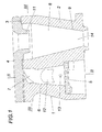
- the combustion chamber 1 is composed of a base body 2 and a lid 4 placed on the base body 2 via a seal 3.
- a shaft 6 rising above a grate 6 as a carburetor section 7 and parallel to this shaft 6, a burnout section 8 in the form of a cyclone separator 9 is formed.
- the cover 4 closes off the shaft 6 and the overflow channel 10 upwards.
- the cover 4 forms a dip tube 11 delimiting the cyclone separator 9 upwards.
- a case loading shaft 12 opening into the shaft 6 is provided in the base body 2. But it can also be a feed with a lateral screw conveyor or be provided from below, because it does not depend on the type of loading of the combustion chamber 1 with fuel.
- a recess 13 for connection of an ignition device is provided for igniting the fuel in the shaft 6.
- the cyclone separator 9 has a downwardly open outlet opening 14 leading into an ashtray, via which the combustion residues separated off from the exhaust gas flow of the burnout section 8 are discharged.
- the exhaust gas cleaned from combustion residues leaves the cyclone separator 9 via the dip tube 11 in order to charge a subsequent heat exchanger.
- the carburetor section 7 of the combustion chamber 1 primary air via the grate 5 is supplied.
- the secondary air required for the burn-out in the burn-out 8 is provided via a Flow channel 15 is provided, which opens in the gusset region between the cyclone 9 and the overflow 10 on the inside, as shown in Fig. 3 evident.
Landscapes
- Engineering & Computer Science (AREA)
- Physics & Mathematics (AREA)
- Chemical & Material Sciences (AREA)
- Combustion & Propulsion (AREA)
- Thermal Sciences (AREA)
- Mechanical Engineering (AREA)
- General Engineering & Computer Science (AREA)
- Structural Engineering (AREA)
- Architecture (AREA)
- Civil Engineering (AREA)
- Solid-Fuel Combustion (AREA)
Applications Claiming Priority (1)
| Application Number | Priority Date | Filing Date | Title |
|---|---|---|---|
| AT0044809U AT11432U1 (de) | 2009-07-20 | 2009-07-20 | Brennkammer für stückeligen brennstoff, insbesondere holzpellets |
Publications (1)
| Publication Number | Publication Date |
|---|---|
| EP2278221A2 true EP2278221A2 (fr) | 2011-01-26 |
Family
ID=42537329
Family Applications (1)
| Application Number | Title | Priority Date | Filing Date |
|---|---|---|---|
| EP10450100A Withdrawn EP2278221A2 (fr) | 2009-07-20 | 2010-06-09 | Chambre de combustion pour carburants en vrac, notamment des granulés de bois |
Country Status (2)
| Country | Link |
|---|---|
| EP (1) | EP2278221A2 (fr) |
| AT (1) | AT11432U1 (fr) |
Cited By (1)
| Publication number | Priority date | Publication date | Assignee | Title |
|---|---|---|---|---|
| AT511878A3 (de) * | 2011-08-31 | 2013-07-15 | Bosch Gmbh Robert | Trichterförmige Sekundärbrennkammer |
Families Citing this family (1)
| Publication number | Priority date | Publication date | Assignee | Title |
|---|---|---|---|---|
| CN103453523A (zh) * | 2013-09-05 | 2013-12-18 | 无锡华光锅炉股份有限公司 | 一种用于循环流化床锅炉的中心筒结构 |
Citations (1)
| Publication number | Priority date | Publication date | Assignee | Title |
|---|---|---|---|---|
| AT414036B (de) | 2004-03-03 | 2006-08-15 | Guntamatic Heiztechnik Gmbh | Feuerung für stückeligen brennstoff aus nachwachsenden rohstoffen, insbesondere für einen heizkessel |
-
2009
- 2009-07-20 AT AT0044809U patent/AT11432U1/de not_active IP Right Cessation
-
2010
- 2010-06-09 EP EP10450100A patent/EP2278221A2/fr not_active Withdrawn
Patent Citations (1)
| Publication number | Priority date | Publication date | Assignee | Title |
|---|---|---|---|---|
| AT414036B (de) | 2004-03-03 | 2006-08-15 | Guntamatic Heiztechnik Gmbh | Feuerung für stückeligen brennstoff aus nachwachsenden rohstoffen, insbesondere für einen heizkessel |
Cited By (2)
| Publication number | Priority date | Publication date | Assignee | Title |
|---|---|---|---|---|
| AT511878A3 (de) * | 2011-08-31 | 2013-07-15 | Bosch Gmbh Robert | Trichterförmige Sekundärbrennkammer |
| AT511878B1 (de) * | 2011-08-31 | 2014-05-15 | Bosch Gmbh Robert | Trichterförmige Sekundärbrennkammer |
Also Published As
| Publication number | Publication date |
|---|---|
| AT11432U1 (de) | 2010-10-15 |
Similar Documents
| Publication | Publication Date | Title |
|---|---|---|
| EP3789672B1 (fr) | Installation de chauffage à la biomasse ayant une conduite d'air secondaire, ainsi que ses parties intégrantes | |
| DE3335544A1 (de) | Reaktorvorrichtung zur erzeugung von generatorgas aus brennbaren abfallprodukten | |
| EP2058589B1 (fr) | Chaudière pour combustible solide | |
| EP1830126B1 (fr) | Chaudière pour combustibles solides biologiques | |
| EP2278221A2 (fr) | Chambre de combustion pour carburants en vrac, notamment des granulés de bois | |
| DE10349365A1 (de) | Vergaserheizkessel für feste Brennstoffe, insbesondere für Strohballen, mit optmierten Abgaswerten | |
| DE102010037768B4 (de) | Vorrichtung zum Vergasen von Biomasse und Verfahren zu deren Betrieb | |
| DE3413564A1 (de) | Verfahren und vorrichtung zur verminderung des ausstosses von stickoxiden | |
| DE3441923A1 (de) | Wirbelschichtofen mit nachgeschalteten konvektionsheizflaechen | |
| AT414036B (de) | Feuerung für stückeligen brennstoff aus nachwachsenden rohstoffen, insbesondere für einen heizkessel | |
| DE102012106580A1 (de) | Rauchgasbetriebene Backofen-Vorrichtung | |
| DE210431C (fr) | ||
| DE102013021894B3 (de) | Brenner und/oder Verfahren zum Betreiben eines Brenners für mit Biofeststoffen befeuerte Öfen | |
| DE102023109038A1 (de) | Verbrennungsanordnung für kontaminierte Abfälle | |
| DE8328140U1 (de) | Reaktorvorrichtung zur Erzeugung von Generatorgas aus brennbaren Abfallprodukten | |
| DE102009008076A1 (de) | Gleichstrom-Festbettvergaser, Stromerzeugungsanordnung und Verfahren zur Erzeugung von Brenngas aus Festbrennstoffen | |
| DE3809429A1 (de) | Brennersystem zur verbrennung von festen brennstoffen in gasfoermigem zustand | |
| DE261048C (fr) | ||
| DE135171C (fr) | ||
| DE3624293C2 (fr) | ||
| EP2775200B1 (fr) | Four comprenant un espace de combustion et une chambre de combustion secondaire | |
| DE202016101023U1 (de) | Rohrförmiges Vergaserbauteil sowie Gleichstrom-Festbettvergaser zum Erzeugen eines Produktgases aus schüttbaren Biomasseteilchen mit einem solchen Vergaserbauteil | |
| AT145263B (de) | Ofen zur Verbrennung von minderwertigen Brennstoffen, wie beispielsweise Müll. | |
| AT143386B (de) | Feuerung mit Füllschacht. | |
| DE4435906C5 (de) | Verfahren und Vorrichtung zum Vergasen von Feststoffen |
Legal Events
| Date | Code | Title | Description |
|---|---|---|---|
| PUAI | Public reference made under article 153(3) epc to a published international application that has entered the european phase |
Free format text: ORIGINAL CODE: 0009012 |
|
| AK | Designated contracting states |
Kind code of ref document: A2 Designated state(s): AL AT BE BG CH CY CZ DE DK EE ES FI FR GB GR HR HU IE IS IT LI LT LU LV MC MK MT NL NO PL PT RO SE SI SK SM TR |
|
| AX | Request for extension of the european patent |
Extension state: BA ME RS |
|
| STAA | Information on the status of an ep patent application or granted ep patent |
Free format text: STATUS: THE APPLICATION IS DEEMED TO BE WITHDRAWN |
|
| 18D | Application deemed to be withdrawn |
Effective date: 20160105 |