EP2278221A2 - Combustion chamber for pelletised fuel, in particular wood pellets - Google Patents
Combustion chamber for pelletised fuel, in particular wood pellets Download PDFInfo
- Publication number
- EP2278221A2 EP2278221A2 EP10450100A EP10450100A EP2278221A2 EP 2278221 A2 EP2278221 A2 EP 2278221A2 EP 10450100 A EP10450100 A EP 10450100A EP 10450100 A EP10450100 A EP 10450100A EP 2278221 A2 EP2278221 A2 EP 2278221A2
- Authority
- EP
- European Patent Office
- Prior art keywords
- section
- shaft
- combustion chamber
- cyclone separator
- carburetor
- Prior art date
- Legal status (The legal status is an assumption and is not a legal conclusion. Google has not performed a legal analysis and makes no representation as to the accuracy of the status listed.)
- Withdrawn
Links
- 238000002485 combustion reaction Methods 0.000 title claims abstract description 33
- 239000008188 pellet Substances 0.000 title claims abstract description 7
- 239000002023 wood Substances 0.000 title claims abstract description 7
- 239000000446 fuel Substances 0.000 title claims description 22
- 238000001816 cooling Methods 0.000 claims abstract description 5
- 230000001174 ascending effect Effects 0.000 claims description 4
- 230000000630 rising effect Effects 0.000 abstract description 2
- 239000007787 solid Substances 0.000 abstract 1
- 239000004449 solid propellant Substances 0.000 abstract 1
- 239000007789 gas Substances 0.000 description 11
- 238000000926 separation method Methods 0.000 description 5
- 239000002245 particle Substances 0.000 description 4
- 230000002349 favourable effect Effects 0.000 description 3
- 230000000694 effects Effects 0.000 description 2
- 238000002309 gasification Methods 0.000 description 2
- 206010067482 No adverse event Diseases 0.000 description 1
- 238000005054 agglomeration Methods 0.000 description 1
- 230000002776 aggregation Effects 0.000 description 1
- 238000010276 construction Methods 0.000 description 1
- 238000009826 distribution Methods 0.000 description 1
- 238000010304 firing Methods 0.000 description 1
- 238000003958 fumigation Methods 0.000 description 1
- 206010022000 influenza Diseases 0.000 description 1
- 238000002844 melting Methods 0.000 description 1
- 230000008018 melting Effects 0.000 description 1
- 230000002093 peripheral effect Effects 0.000 description 1
- 239000002994 raw material Substances 0.000 description 1
- 238000009827 uniform distribution Methods 0.000 description 1
Images


Classifications
-
- F—MECHANICAL ENGINEERING; LIGHTING; HEATING; WEAPONS; BLASTING
- F23—COMBUSTION APPARATUS; COMBUSTION PROCESSES
- F23B—METHODS OR APPARATUS FOR COMBUSTION USING ONLY SOLID FUEL
- F23B80/00—Combustion apparatus characterised by means creating a distinct flow path for flue gases or for non-combusted gases given off by the fuel
-
- E—FIXED CONSTRUCTIONS
- E06—DOORS, WINDOWS, SHUTTERS, OR ROLLER BLINDS IN GENERAL; LADDERS
- E06B—FIXED OR MOVABLE CLOSURES FOR OPENINGS IN BUILDINGS, VEHICLES, FENCES OR LIKE ENCLOSURES IN GENERAL, e.g. DOORS, WINDOWS, BLINDS, GATES
- E06B9/00—Screening or protective devices for wall or similar openings, with or without operating or securing mechanisms; Closures of similar construction
- E06B9/24—Screens or other constructions affording protection against light, especially against sunshine; Similar screens for privacy or appearance; Slat blinds
- E06B9/26—Lamellar or like blinds, e.g. venetian blinds
- E06B9/28—Lamellar or like blinds, e.g. venetian blinds with horizontal lamellae, e.g. non-liftable
- E06B9/30—Lamellar or like blinds, e.g. venetian blinds with horizontal lamellae, e.g. non-liftable liftable
- E06B9/303—Lamellar or like blinds, e.g. venetian blinds with horizontal lamellae, e.g. non-liftable liftable with ladder-tape
-
- E—FIXED CONSTRUCTIONS
- E06—DOORS, WINDOWS, SHUTTERS, OR ROLLER BLINDS IN GENERAL; LADDERS
- E06B—FIXED OR MOVABLE CLOSURES FOR OPENINGS IN BUILDINGS, VEHICLES, FENCES OR LIKE ENCLOSURES IN GENERAL, e.g. DOORS, WINDOWS, BLINDS, GATES
- E06B9/00—Screening or protective devices for wall or similar openings, with or without operating or securing mechanisms; Closures of similar construction
- E06B9/24—Screens or other constructions affording protection against light, especially against sunshine; Similar screens for privacy or appearance; Slat blinds
- E06B9/26—Lamellar or like blinds, e.g. venetian blinds
- E06B9/38—Other details
- E06B9/386—Details of lamellae
-
- F—MECHANICAL ENGINEERING; LIGHTING; HEATING; WEAPONS; BLASTING
- F23—COMBUSTION APPARATUS; COMBUSTION PROCESSES
- F23B—METHODS OR APPARATUS FOR COMBUSTION USING ONLY SOLID FUEL
- F23B10/00—Combustion apparatus characterised by the combination of two or more combustion chambers
-
- F—MECHANICAL ENGINEERING; LIGHTING; HEATING; WEAPONS; BLASTING
- F23—COMBUSTION APPARATUS; COMBUSTION PROCESSES
- F23B—METHODS OR APPARATUS FOR COMBUSTION USING ONLY SOLID FUEL
- F23B60/00—Combustion apparatus in which the fuel burns essentially without moving
- F23B60/02—Combustion apparatus in which the fuel burns essentially without moving with combustion air supplied through a grate
-
- F—MECHANICAL ENGINEERING; LIGHTING; HEATING; WEAPONS; BLASTING
- F23—COMBUSTION APPARATUS; COMBUSTION PROCESSES
- F23B—METHODS OR APPARATUS FOR COMBUSTION USING ONLY SOLID FUEL
- F23B80/00—Combustion apparatus characterised by means creating a distinct flow path for flue gases or for non-combusted gases given off by the fuel
- F23B80/04—Combustion apparatus characterised by means creating a distinct flow path for flue gases or for non-combusted gases given off by the fuel by means for guiding the flow of flue gases, e.g. baffles
-
- F—MECHANICAL ENGINEERING; LIGHTING; HEATING; WEAPONS; BLASTING
- F23—COMBUSTION APPARATUS; COMBUSTION PROCESSES
- F23J—REMOVAL OR TREATMENT OF COMBUSTION PRODUCTS OR COMBUSTION RESIDUES; FLUES
- F23J2217/00—Intercepting solids
- F23J2217/40—Intercepting solids by cyclones
Definitions
- the invention relates to a combustion chamber for lumpy fuel, in particular wood pellets, with a carburetor section which receives the fuel and a combustion section which adjoins the carburetor section and forms a cyclone separator.
- the axis of the carburetor section extends transversely to the axis of the cyclone separator forming the burnout section in order to be able to transfer the exhaust gases from the carburetor section as tangentially as possible into the cyclone separator, not only does a corresponding lateral space requirement arise, but also with certain restrictions with regard to the charging of the carburetor section be calculated with fuel. In addition, it has been found that it is difficult to ensure favorable combustion conditions for the fuel in the gasifier section of the combustion chamber.
- the invention is therefore based on the object, a combustion chamber for lumpy fuel, especially wood pellets, of the type described in such a way that despite an improved pre-combustion of lumpy fuel in the carburetor section no adverse effects in the field of afterburning and the separation of the combustion residues from the exhaust gases Burn-out zone must be taken into account.
- the invention solves this problem by the fact that the carburetor section forms a laterally provided next to the cyclone, ascending shaft which is connected to the cyclone separator via an upper, tangentially opening into the cyclone overflow channel.
- the carburetor section of the combustion chamber forms an ascending shaft provided laterally next to the cyclone separator, the result is initially a space-saving, compact construction.
- the ascending shaft of the carburetor section also offers particularly advantageous firing conditions for the lumpy fuel, because due to the shaft guide experienced with the resulting exhaust gases fuel particles in the exhaust stream undergo a largely uniform distribution.
- the residence time of the fuel particles in the shaft depending on the mass of these particles regulates itself.
- the cyclone of the burn-out substantially parallel shaft of the carburetor section can be taken care of a good separation of the combustion residues through the cyclone when the shaft of the carburetor with the Zyklonabscheider is connected via an upper, tangentially opening into the cyclone overflow channel, whose mouth course so regardless of the shaft arrangement in the cyclone can be involved so that within the cyclone, preferably in the range of a dip tube for the exhaust system, an advantageous circulation flow adjusting, which ensures a sufficient burn-out without endangering the extensive separation of the combustion residues from the exhaust stream, which is withdrawn via the dip tube.
- the side of the cyclone provided next to the slot of the carburetor also offers the opportunity to influence the exhaust gas temperature within the shaft, because the outer wall of the carburetor can be formed as a cooling zone. Cooling in the region of the carburetor section reduces the risk of liquefaction of the forming ash, which increases the reliability of the combustion chamber. In the subsequent burn-out zone, a temperature-induced agglomeration of the combustion residues for easier separation from the exhaust gas stream is desired.
- the effect of the fumigation of the gasifier section is of particular importance with regard to the combustion conditions for the fuel.
- this fouling effect can be used particularly advantageous, is to ensure a sufficiently slim shaft.
- Particularly favorable conditions arise in this context when the diameter at the lower end of the shaft corresponds to at most half of the shaft height and the shaft height is smaller than the cyclone height.
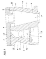
- the combustion chamber 1 is composed of a base body 2 and a lid 4 placed on the base body 2 via a seal 3.
- a shaft 6 rising above a grate 6 as a carburetor section 7 and parallel to this shaft 6, a burnout section 8 in the form of a cyclone separator 9 is formed.
- the cover 4 closes off the shaft 6 and the overflow channel 10 upwards.
- the cover 4 forms a dip tube 11 delimiting the cyclone separator 9 upwards.
- a case loading shaft 12 opening into the shaft 6 is provided in the base body 2. But it can also be a feed with a lateral screw conveyor or be provided from below, because it does not depend on the type of loading of the combustion chamber 1 with fuel.
- a recess 13 for connection of an ignition device is provided for igniting the fuel in the shaft 6.
- the cyclone separator 9 has a downwardly open outlet opening 14 leading into an ashtray, via which the combustion residues separated off from the exhaust gas flow of the burnout section 8 are discharged.
- the exhaust gas cleaned from combustion residues leaves the cyclone separator 9 via the dip tube 11 in order to charge a subsequent heat exchanger.
- the carburetor section 7 of the combustion chamber 1 primary air via the grate 5 is supplied.
- the secondary air required for the burn-out in the burn-out 8 is provided via a Flow channel 15 is provided, which opens in the gusset region between the cyclone 9 and the overflow 10 on the inside, as shown in Fig. 3 evident.
Landscapes
- Engineering & Computer Science (AREA)
- Physics & Mathematics (AREA)
- Chemical & Material Sciences (AREA)
- Combustion & Propulsion (AREA)
- Thermal Sciences (AREA)
- Mechanical Engineering (AREA)
- General Engineering & Computer Science (AREA)
- Structural Engineering (AREA)
- Architecture (AREA)
- Civil Engineering (AREA)
- Solid-Fuel Combustion (AREA)
Abstract
Description
Die Erfindung bezieht sich auf eine Brennkammer für stückeligen Brennstoff, insbesondere Holzpellets, mit einem den Brennstoff aufnehmenden Vergaserabschnitt und einem an den Vergaserabschnitt anschließenden, als Zyklonabscheider ausgebildeten Ausbrandabschnitt.The invention relates to a combustion chamber for lumpy fuel, in particular wood pellets, with a carburetor section which receives the fuel and a combustion section which adjoins the carburetor section and forms a cyclone separator.
Um einerseits vorteilhafte Verbrennungsverhältnisse für stückelige Brennstoffe auf der Basis nachwachsender Rohstoffe, insbesondere Holzpellets, zu ermöglichen und anderseits die bei solchen Brennstoffen erhöhte Gefahr von Brennstoffablagerungen im Abgaszug eines Heizkessels zu vermeiden, wurde bereits vorgeschlagen (
Der Erfindung liegt somit die Aufgabe zugrunde, eine Brennkammer für stückeligen Brennstoff, insbesondere Holzpellets, der eingangs geschilderten Art so auszugestalten, dass trotz einer verbesserten Vorverbrennung des stückeligen Brennstoffs im Vergaserabschnitt keine nachteiligen Einflüsse im Bereich der Nachverbrennung und der Abscheidung der Brennrückstände aus den Abgasen der Ausbrandzone in Kauf genommen werden müssen.The invention is therefore based on the object, a combustion chamber for lumpy fuel, especially wood pellets, of the type described in such a way that despite an improved pre-combustion of lumpy fuel in the carburetor section no adverse effects in the field of afterburning and the separation of the combustion residues from the exhaust gases Burn-out zone must be taken into account.
Die Erfindung löst die gestellte Aufgabe dadurch, dass der Vergaserabschnitt einen seitlich neben dem Zyklonabscheider vorgesehenen, aufsteigenden Schacht bildet, der mit dem Zyklonabscheider über einen oberen, tangential in den Zyklonabscheider mündenden Überströmkanal verbunden ist.The invention solves this problem by the fact that the carburetor section forms a laterally provided next to the cyclone, ascending shaft which is connected to the cyclone separator via an upper, tangentially opening into the cyclone overflow channel.
Da der Vergaserabschnitt der Brennkammer einen seitlich neben dem Zyklonabscheider vorgesehenen, aufsteigenden Schacht bildet, ergibt sich zunächst eine platzsparende, kompakte Konstruktion. Der aufsteigende Schacht des Vergaserabschnitts bietet darüber hinaus besonders vorteilhafte Feuerungsbedingungen für den stückeligen Brennstoff, weil aufgrund der Schachtführung die mit den entstehenden Abgasen mitgeführten Brennstoffteilchen im Abgasstrom eine weitgehend gleichmäßige Verteilung erfahren. Außerdem regelt sich die Verweilzeit der Brennstoffteilchen im Schacht in Abhängigkeit von der Masse dieser Teilchen von selbst. Trotz des zum Zyklonabscheider des Ausbrandabschnitts im Wesentlichen parallelen Schachts des Vergaserabschnitts kann für eine gute Abscheidung der Brennrückstände durch den Zyklonabscheider gesorgt werden, wenn der Schacht des Vergaserabschnitts mit dem Zyklonabscheider über einen oberen, tangential in den Zyklonabscheider mündenden Überströmkanal verbunden wird, dessen Mündungsverlauf ja unabhängig von der Schachtanordnung in den Zyklonabscheider so eingebunden werden kann, dass sich innerhalb des Zyklonabscheiders, und zwar vorzugsweise im Bereich eines Tauchrohres für die Abgasführung, eine vorteilhafte Umlaufströmung einstellt, die eine ausreichende Ausbrandstrecke sicherstellt, ohne die weitgehende Abscheidung der Brennrückstände aus dem Abgasstrom zu gefährden, der über das Tauchrohr abgezogen wird.Since the carburetor section of the combustion chamber forms an ascending shaft provided laterally next to the cyclone separator, the result is initially a space-saving, compact construction. The ascending shaft of the carburetor section also offers particularly advantageous firing conditions for the lumpy fuel, because due to the shaft guide experienced with the resulting exhaust gases fuel particles in the exhaust stream undergo a largely uniform distribution. In addition, the residence time of the fuel particles in the shaft depending on the mass of these particles regulates itself. Despite the cyclone of the burn-out substantially parallel shaft of the carburetor section can be taken care of a good separation of the combustion residues through the cyclone when the shaft of the carburetor with the Zyklonabscheider is connected via an upper, tangentially opening into the cyclone overflow channel, whose mouth course so regardless of the shaft arrangement in the cyclone can be involved so that within the cyclone, preferably in the range of a dip tube for the exhaust system, an advantageous circulation flow adjusting, which ensures a sufficient burn-out without endangering the extensive separation of the combustion residues from the exhaust stream, which is withdrawn via the dip tube.
Obwohl von einem Kreisquerschnitt abweichende Strömungsquerschnitte für den Schacht des Vergaserabschnitts durchaus möglich sind, ergeben sich besonders vorteilhafte Verbrennungsbedingungen, wenn der Vergaserabschnitt einen Schacht mit einem zylindrischen Verlauf oder einen vom zylindrischen Verlauf konisch abweichenden Verlauf aufweist. Runde Schachtquerschnitte stellen vorteilhafte Voraussetzungen für eine weitgehend gleichmäßige Strömungsverteilung über den Schachtquerschnitt dar, wobei mit einer konischen Erweiterung nach oben die zunehmende Vergasung der Brennstoffteilchen berücksichtigt werden kann.Although flow cross sections differing from a circular cross section are entirely possible for the shaft of the carburetor section, particularly advantageous combustion conditions result if the carburettor section has a shaft with a cylindrical course or a course deviating conically from the cylindrical course. Round shaft cross-sections represent advantageous conditions for a largely uniform flow distribution over the shaft cross-section, with a conical expansion upwards, the increasing gasification of the fuel particles can be considered.
Der seitlich neben dem Zyklonabscheider vorgesehene Schacht des Vergaserabschnitts bietet außerdem die Möglichkeit, Einfluss auf die Abgastemperatur innerhalb des Schachts zu nehmen, weil die Außenwand des Vergaserabschnitts als Kühlzone ausgebildet werden kann. Eine Kühlung im Bereich des Vergaserabschnitts vermindert die Gefahr der Verflüssigung der sich bildenden Asche, was die Betriebssicherheit der Brennkammer erhöht. In der anschließenden Ausbrandzone ist eine temperaturbedingte Verklumpung der Brennrückstände zur leichteren Abscheidung aus dem Abgasstrom erwünscht.The side of the cyclone provided next to the slot of the carburetor also offers the opportunity to influence the exhaust gas temperature within the shaft, because the outer wall of the carburetor can be formed as a cooling zone. Cooling in the region of the carburetor section reduces the risk of liquefaction of the forming ash, which increases the reliability of the combustion chamber. In the subsequent burn-out zone, a temperature-induced agglomeration of the combustion residues for easier separation from the exhaust gas stream is desired.
Wie bereits ausgeführt wurde, kommt der Schachtwirkung des Vergaserabschnitts eine besondere Bedeutung im Hinblick auf die Verbrennungsbedingungen für den Brennstoff zu. Damit diese Schachtwirkung besonders vorteilhaft genützt werden kann, ist für einen ausreichend schlanken Schacht zu sorgen. Besonders günstige Verhältnisse ergeben sich in diesem Zusammenhang, wenn der Durchmesser am unteren Ende des Schachts höchstens der Hälfe der Schachthöhe entspricht und die Schachthöhe kleiner als die Zyklonhöhe ist.As has already been stated, the effect of the fumigation of the gasifier section is of particular importance with regard to the combustion conditions for the fuel. In order for this fouling effect can be used particularly advantageous, is to ensure a sufficiently slim shaft. Particularly favorable conditions arise in this context when the diameter at the lower end of the shaft corresponds to at most half of the shaft height and the shaft height is smaller than the cyclone height.
In der Zeichnung ist der Erfindungsgegenstand beispielsweise dargestellt. Es zeigen
-
Fig. 1 eine erfindungsgemäße Brennkammer in einem vereinfachten Längsschnitt, -
Fig. 2 diese Brennkammer im Schnitt nach der Linie II-II derFig. 1 und -
Fig. 3 einen Schnitt nach der Linie III-III derFig. 1 .
-
Fig. 1 a combustion chamber according to the invention in a simplified longitudinal section, -
Fig. 2 this combustion chamber in section along the line II-II of theFig. 1 and -
Fig. 3 a section along the line III-III ofFig. 1 ,
Gemäß dem dargestellten Ausführungsbeispiel setzt sich die Brennkammer 1 aus einem Grundkörper 2 und einem auf den Grundkörper 2 über eine Dichtung 3 aufgesetzten Deckel 4 zusammen. Im Grundkörper 2 ist einerseits ein über einem Rost 5 aufragender Schacht 6 als Vergaserabschnitt 7 und parallel neben diesem Schacht 6 ein Ausbrandabschnitt 8 in Form eines Zyklonabscheiders 9 ausgebildet. Ein im oberen Stirnbereich des Grundkörpers 2 ausgesparter Überströmkanal 10 zwischen dem Vergaserabschnitt 7 und dem Ausbrandabschnitt 8 mündet tangential in den Zyklonabscheider 9, wie dies insbesondere der
Zum Befüllen des Vergaserabschnitts 7 mit stückeligem Brennstoff, vorzugsweise Holzpellets, ist im Grundkörper 2 ein im Schacht 6 mündender Fallbeschickungsschacht 12 vorgesehen. Es kann aber auch eine Beschickung mit einer seitlichen Förderschnecke oder von unten vorgesehen werden, weil es nicht auf die Art der Beschickung der Brennkammer 1 mit Brennstoff ankommt. Zur Zündung des Brennstoffs im Schacht 6 ist eine Aussparung 13 zum Anschluss einer Zündvorrichtung vorgesehen.For filling the
Der Zyklonabscheider 9 weist eine nach unten offene, in einen Ascheraum führende Austrittsöffnung 14 auf, über die die aus dem Abgasstrom des Ausbrandabschnitts 8 abgeschiedenen Brennrückstände ausgetragen werden. Das von Brennrückständen gereinigte Abgas verlässt den Zyklonabscheider 9 über das Tauchrohr 11, um einen anschließenden Wärmetauscher zu beaufschlagen.The
Wie den
Da die Vorverbrennung der stückeligen Brennstoffe im Vergaserabschnitt 7 der Brennkammer 1 in einem Schacht 6 erfolgt, ergeben sich besonders vorteilhafte Verbrennungs- und Vergasungsbedingungen, wobei aufgrund der Nebeneinanderreihung des Schachts 6 und des Zyklonabscheiders 9 günstige Raumverhältnisse eingehalten werden können. Die Nebeneinanderreihung des Vergaserabschnitts 7 und des Ausbrandabschnitts 8 stellt außerdem eine einfache Voraussetzung dar, um auf die Abgastemperatur des Vergaserabschnitts 7 Einfluss zu nehmen. Wie der
Claims (4)
Applications Claiming Priority (1)
| Application Number | Priority Date | Filing Date | Title |
|---|---|---|---|
| AT0044809U AT11432U1 (en) | 2009-07-20 | 2009-07-20 | COMBUSTION CHAMBER FOR PARTICULAR FUEL, ESPECIALLY WOOD PELLETS |
Publications (1)
| Publication Number | Publication Date |
|---|---|
| EP2278221A2 true EP2278221A2 (en) | 2011-01-26 |
Family
ID=42537329
Family Applications (1)
| Application Number | Title | Priority Date | Filing Date |
|---|---|---|---|
| EP10450100A Withdrawn EP2278221A2 (en) | 2009-07-20 | 2010-06-09 | Combustion chamber for pelletised fuel, in particular wood pellets |
Country Status (2)
| Country | Link |
|---|---|
| EP (1) | EP2278221A2 (en) |
| AT (1) | AT11432U1 (en) |
Cited By (1)
| Publication number | Priority date | Publication date | Assignee | Title |
|---|---|---|---|---|
| AT511878A3 (en) * | 2011-08-31 | 2013-07-15 | Bosch Gmbh Robert | Funnel-shaped secondary combustion chamber |
Families Citing this family (1)
| Publication number | Priority date | Publication date | Assignee | Title |
|---|---|---|---|---|
| CN103453523A (en) * | 2013-09-05 | 2013-12-18 | 无锡华光锅炉股份有限公司 | Center cylinder structure for circulating fluidized bed boiler |
Citations (1)
| Publication number | Priority date | Publication date | Assignee | Title |
|---|---|---|---|---|
| AT414036B (en) | 2004-03-03 | 2006-08-15 | Guntamatic Heiztechnik Gmbh | FIRE FOR PARTICULAR FUEL FROM RENEWABLE RAW MATERIALS, ESPECIALLY FOR A BOILER |
-
2009
- 2009-07-20 AT AT0044809U patent/AT11432U1/en not_active IP Right Cessation
-
2010
- 2010-06-09 EP EP10450100A patent/EP2278221A2/en not_active Withdrawn
Patent Citations (1)
| Publication number | Priority date | Publication date | Assignee | Title |
|---|---|---|---|---|
| AT414036B (en) | 2004-03-03 | 2006-08-15 | Guntamatic Heiztechnik Gmbh | FIRE FOR PARTICULAR FUEL FROM RENEWABLE RAW MATERIALS, ESPECIALLY FOR A BOILER |
Cited By (2)
| Publication number | Priority date | Publication date | Assignee | Title |
|---|---|---|---|---|
| AT511878A3 (en) * | 2011-08-31 | 2013-07-15 | Bosch Gmbh Robert | Funnel-shaped secondary combustion chamber |
| AT511878B1 (en) * | 2011-08-31 | 2014-05-15 | Bosch Gmbh Robert | Funnel-shaped secondary combustion chamber |
Also Published As
| Publication number | Publication date |
|---|---|
| AT11432U1 (en) | 2010-10-15 |
Similar Documents
| Publication | Publication Date | Title |
|---|---|---|
| EP3789672B1 (en) | Biomass heating system with secondary air conduit, and components of same | |
| DE3335544A1 (en) | REACTOR DEVICE FOR GENERATING GENERATOR GAS FROM COMBUSTIBLE WASTE PRODUCTS | |
| EP2058589B1 (en) | Boiler for solid fuel | |
| EP1830126B1 (en) | Boiler for solid bio fuel | |
| EP2278221A2 (en) | Combustion chamber for pelletised fuel, in particular wood pellets | |
| DE10349365A1 (en) | Carburetted boilers for solid fuels, in particular for straw bales, with optimized exhaust gas values | |
| DE102010037768B4 (en) | Device for gasifying biomass and method for its operation | |
| DE3413564A1 (en) | Method and device for reducing the discharge of nitrogen oxides | |
| DE3441923A1 (en) | Fluidised-bed furnace with downstream convection heating surfaces | |
| AT414036B (en) | FIRE FOR PARTICULAR FUEL FROM RENEWABLE RAW MATERIALS, ESPECIALLY FOR A BOILER | |
| DE102012106580A1 (en) | Oven device, has oven comprising aperture for discharging gaseous mixture, which is formed by partial combustion of combustible components of another mixture that is partially formed by flue gases under admixture of additional air | |
| DE210431C (en) | ||
| DE102013021894B3 (en) | Burner and / or method of operating a burner for bio-solids fired ovens | |
| DE102023109038A1 (en) | incineration arrangement for contaminated waste | |
| DE8328140U1 (en) | Reactor device for producing generator gas from combustible waste products | |
| DE102009008076A1 (en) | Direct current-fixed bed gasifier for use in power generation arrangement for producing fuel gas from e.g. wood chips, has bottom shear reactor whose shaft is supplied with solid fuel, and hot gas filter arranged in closed housings | |
| DE3809429A1 (en) | BURNER SYSTEM FOR COMBUSTION OF SOLID FUELS IN GASEOUS CONDITION | |
| DE261048C (en) | ||
| DE135171C (en) | ||
| DE3624293C2 (en) | ||
| DE573566C (en) | Chute heater | |
| EP2775200B1 (en) | Oven with a combustion chamber and a secondary combustion chamber | |
| DE202016101023U1 (en) | Tubular carburetor component and DC fixed-bed gasifier for producing a product gas from flowable biomass particles with such a carburetor component | |
| AT145263B (en) | Furnace for burning low quality fuels such as garbage. | |
| AT143386B (en) | Firing with filling shaft. |
Legal Events
| Date | Code | Title | Description |
|---|---|---|---|
| PUAI | Public reference made under article 153(3) epc to a published international application that has entered the european phase |
Free format text: ORIGINAL CODE: 0009012 |
|
| AK | Designated contracting states |
Kind code of ref document: A2 Designated state(s): AL AT BE BG CH CY CZ DE DK EE ES FI FR GB GR HR HU IE IS IT LI LT LU LV MC MK MT NL NO PL PT RO SE SI SK SM TR |
|
| AX | Request for extension of the european patent |
Extension state: BA ME RS |
|
| STAA | Information on the status of an ep patent application or granted ep patent |
Free format text: STATUS: THE APPLICATION IS DEEMED TO BE WITHDRAWN |
|
| 18D | Application deemed to be withdrawn |
Effective date: 20160105 |