EP2278207A2 - Stand mounting structure and rear cabinet - Google Patents
Stand mounting structure and rear cabinet Download PDFInfo
- Publication number
- EP2278207A2 EP2278207A2 EP10170445A EP10170445A EP2278207A2 EP 2278207 A2 EP2278207 A2 EP 2278207A2 EP 10170445 A EP10170445 A EP 10170445A EP 10170445 A EP10170445 A EP 10170445A EP 2278207 A2 EP2278207 A2 EP 2278207A2
- Authority
- EP
- European Patent Office
- Prior art keywords
- stand
- hook
- mounting part
- display unit
- rear cabinet
- Prior art date
- Legal status (The legal status is an assumption and is not a legal conclusion. Google has not performed a legal analysis and makes no representation as to the accuracy of the status listed.)
- Withdrawn
Links
- 230000003014 reinforcing effect Effects 0.000 claims abstract description 67
- 230000002123 temporal effect Effects 0.000 claims abstract description 48
- 238000003780 insertion Methods 0.000 claims abstract description 40
- 230000037431 insertion Effects 0.000 claims abstract description 40
- 239000004973 liquid crystal related substance Substances 0.000 claims abstract description 16
- 230000002093 peripheral effect Effects 0.000 claims description 16
- 238000000465 moulding Methods 0.000 claims description 4
- 239000011347 resin Substances 0.000 claims description 4
- 229920005989 resin Polymers 0.000 claims description 4
- 230000002787 reinforcement Effects 0.000 claims 1
- 238000010586 diagram Methods 0.000 description 7
- 238000004519 manufacturing process Methods 0.000 description 4
- 238000000034 method Methods 0.000 description 3
- 238000005452 bending Methods 0.000 description 2
- 230000000717 retained effect Effects 0.000 description 2
- 230000000630 rising effect Effects 0.000 description 2
- 238000010276 construction Methods 0.000 description 1
- 238000005728 strengthening Methods 0.000 description 1
Images

Classifications
-
- F—MECHANICAL ENGINEERING; LIGHTING; HEATING; WEAPONS; BLASTING
- F16—ENGINEERING ELEMENTS AND UNITS; GENERAL MEASURES FOR PRODUCING AND MAINTAINING EFFECTIVE FUNCTIONING OF MACHINES OR INSTALLATIONS; THERMAL INSULATION IN GENERAL
- F16M—FRAMES, CASINGS OR BEDS OF ENGINES, MACHINES OR APPARATUS, NOT SPECIFIC TO ENGINES, MACHINES OR APPARATUS PROVIDED FOR ELSEWHERE; STANDS; SUPPORTS
- F16M11/00—Stands or trestles as supports for apparatus or articles placed thereon ; Stands for scientific apparatus such as gravitational force meters
-
- F—MECHANICAL ENGINEERING; LIGHTING; HEATING; WEAPONS; BLASTING
- F16—ENGINEERING ELEMENTS AND UNITS; GENERAL MEASURES FOR PRODUCING AND MAINTAINING EFFECTIVE FUNCTIONING OF MACHINES OR INSTALLATIONS; THERMAL INSULATION IN GENERAL
- F16M—FRAMES, CASINGS OR BEDS OF ENGINES, MACHINES OR APPARATUS, NOT SPECIFIC TO ENGINES, MACHINES OR APPARATUS PROVIDED FOR ELSEWHERE; STANDS; SUPPORTS
- F16M11/00—Stands or trestles as supports for apparatus or articles placed thereon ; Stands for scientific apparatus such as gravitational force meters
- F16M11/02—Heads
- F16M11/04—Means for attachment of apparatus; Means allowing adjustment of the apparatus relatively to the stand
- F16M11/041—Allowing quick release of the apparatus
-
- F—MECHANICAL ENGINEERING; LIGHTING; HEATING; WEAPONS; BLASTING
- F16—ENGINEERING ELEMENTS AND UNITS; GENERAL MEASURES FOR PRODUCING AND MAINTAINING EFFECTIVE FUNCTIONING OF MACHINES OR INSTALLATIONS; THERMAL INSULATION IN GENERAL
- F16M—FRAMES, CASINGS OR BEDS OF ENGINES, MACHINES OR APPARATUS, NOT SPECIFIC TO ENGINES, MACHINES OR APPARATUS PROVIDED FOR ELSEWHERE; STANDS; SUPPORTS
- F16M11/00—Stands or trestles as supports for apparatus or articles placed thereon ; Stands for scientific apparatus such as gravitational force meters
- F16M11/02—Heads
- F16M11/16—Details concerning attachment of head-supporting legs, with or without actuation of locking members thereof
-
- F—MECHANICAL ENGINEERING; LIGHTING; HEATING; WEAPONS; BLASTING
- F16—ENGINEERING ELEMENTS AND UNITS; GENERAL MEASURES FOR PRODUCING AND MAINTAINING EFFECTIVE FUNCTIONING OF MACHINES OR INSTALLATIONS; THERMAL INSULATION IN GENERAL
- F16M—FRAMES, CASINGS OR BEDS OF ENGINES, MACHINES OR APPARATUS, NOT SPECIFIC TO ENGINES, MACHINES OR APPARATUS PROVIDED FOR ELSEWHERE; STANDS; SUPPORTS
- F16M11/00—Stands or trestles as supports for apparatus or articles placed thereon ; Stands for scientific apparatus such as gravitational force meters
- F16M11/20—Undercarriages with or without wheels
- F16M11/22—Undercarriages with or without wheels with approximately constant height, e.g. with constant length of column or of legs
-
- F—MECHANICAL ENGINEERING; LIGHTING; HEATING; WEAPONS; BLASTING
- F16—ENGINEERING ELEMENTS AND UNITS; GENERAL MEASURES FOR PRODUCING AND MAINTAINING EFFECTIVE FUNCTIONING OF MACHINES OR INSTALLATIONS; THERMAL INSULATION IN GENERAL
- F16M—FRAMES, CASINGS OR BEDS OF ENGINES, MACHINES OR APPARATUS, NOT SPECIFIC TO ENGINES, MACHINES OR APPARATUS PROVIDED FOR ELSEWHERE; STANDS; SUPPORTS
- F16M2200/00—Details of stands or supports
- F16M2200/08—Foot or support base
-
- Y—GENERAL TAGGING OF NEW TECHNOLOGICAL DEVELOPMENTS; GENERAL TAGGING OF CROSS-SECTIONAL TECHNOLOGIES SPANNING OVER SEVERAL SECTIONS OF THE IPC; TECHNICAL SUBJECTS COVERED BY FORMER USPC CROSS-REFERENCE ART COLLECTIONS [XRACs] AND DIGESTS
- Y10—TECHNICAL SUBJECTS COVERED BY FORMER USPC
- Y10S—TECHNICAL SUBJECTS COVERED BY FORMER USPC CROSS-REFERENCE ART COLLECTIONS [XRACs] AND DIGESTS
- Y10S248/00—Supports
- Y10S248/917—Video display screen support
-
- Y—GENERAL TAGGING OF NEW TECHNOLOGICAL DEVELOPMENTS; GENERAL TAGGING OF CROSS-SECTIONAL TECHNOLOGIES SPANNING OVER SEVERAL SECTIONS OF THE IPC; TECHNICAL SUBJECTS COVERED BY FORMER USPC CROSS-REFERENCE ART COLLECTIONS [XRACs] AND DIGESTS
- Y10—TECHNICAL SUBJECTS COVERED BY FORMER USPC
- Y10S—TECHNICAL SUBJECTS COVERED BY FORMER USPC CROSS-REFERENCE ART COLLECTIONS [XRACs] AND DIGESTS
- Y10S248/00—Supports
- Y10S248/917—Video display screen support
- Y10S248/918—Ancillary device support associated with a video display screen
Definitions
- the present invention relates to a stand attachment structure for attaching a stand that supports a flat panel display unit, such as a liquid crystal display, in an upright position, and to a rear cabinet.
- a flat panel display unit such as a liquid crystal display
- display apparatuses in which a liquid crystal module equipped with a liquid crystal panel and a drive unit is retained between a front cabinet and a rear cabinet to constitute a display unit, and a stand for holding the display unit in an upright position is attached to the display unit.
- Such a stand is typically connected to a lower side or a back side of the display unit, and fixed with screws to a predetermined location on a casing (for example, a rear cabinet) which constitutes the display unit.
- a casing for example, a rear cabinet
- the stand be temporarily fixed at a predetermined location of the display unit, and then secured with the screws.
- a screw insertion hole in a rear cabinet dispose, on an inner side of the rear cabinet, a retainer member which has a tapped hole, and secure an externally disposed stand member with screws.
- a liquid crystal television set and a display apparatus are already suggested (for example, in Japanese Patent Laid-Open Publication No. 2006-173849 ), in which a hook is disposed on an inner surface side of the rear cabinet, and after the retainer member having a hook engaging hole is temporarily fixed to the hook, the stand member is installed from an external surface side of the rear cabinet, and subsequently secured with screws inserted from the screw insertion hole formed in the rear cabinet and screwed into the tapped hole formed in the retainer member.
- There is another type of display apparatus including a display unit and a stand which are to be separately packed as individual components, thereby necessitating operation of a user who have purchased the display apparatus to assemble the display unit and the stand on his/her own.
- the stand can be temporarily fixed at a predetermined location to the display unit, and then secured with screws, positioning and screwing can be facilitated, with a result that the user himself or herself can perform operation of attaching the stand easily and safely.
- the hook member or other members in a temporal fixing part should be resistant to breakage, or temporarily fixing and subsequently screwing operation should be performed safely without the danger of squeezing a finger.
- a way of attaching the lightweight stand member to the display unit placed on a table or the like is safer and easier than a way of securing the display unit placed on the stand.
- a method for attaching the stand to the display unit at a bottom which is transversely situated when the display unit is horizontally laid down is desirable. Then, it is further desirable that the stand can be temporarily fixed at a predetermined position for stand attachment in a predetermined orientation without inclining. Still further, it is also desirable that the temporarily fixed stand can be secured using the screws as it is temporarily fixed without the need to hold the stand in one hand.
- the display unit of a type in which the liquid crystal module is retained in a casing composed of a front cabinet and a rear cabinet it is desirable to dispose a stand mounting part on a bottom surface of the rear cabinet, and provide the stand mounting part with a temporal fixing means for temporarily fixing the stand in safe without the danger of squeezing a finger. Further, it is also desirable that operation of final fixing with the screws be readily achieved, and the temporal fixing means should resist to breakage.
- the present invention which was conceived in view of the above problems, aims to provide a stand attachment structure with which a stand can be temporarily fixed to a display unit with safe operation, and finally secured after the temporal fixing, to thereby allow easy and safe attachment of the stand, and also provide a rear cabinet including a stand mounting part which provides capabilities of temporarily fixing the stand, and of making operation of temporarily fixing and screwing the stand easy and reliable.
- the stand attachment structure comprises a display unit incorporating a liquid crystal module, a front cabinet, and a rear cabinet, and including a stand mounting part provided with a temporal fixing means which is composed of a hook for retaining a stand in a predetermined orientation and a reinforcing rib having functions of reinforcing the hook and of guiding an engagement tab disposed on the stand for insertion, and the stand which is to be attached to the stand mounting part, and is equipped with the engagement tab to be engaged with the hook.
- the stand is temporarily fixed to the display unit by engaging the engagement tab with the hook and, after the temporal fixing, finally secured to the display unit with a screw.
- the stand is temporarily fixed in the predetermined orientation to the stand mounting part of the display unit through the temporal fixing means composed of the hook and the reinforcing rib, which allows co-fastening of the stand to the display unit using a set screw after the temporal fixing, to thereby firmly secure the stand and the display unit.
- the reinforcing rib which has the functions of reinforcing the hook and of guiding the engagement tab for insertion can facilitate operation of temporarily fixing the stand readily and safely without causing the hooks to be broken, leading to easy and safe attachment of the stand.
- the present invention is characterized in that, in the above-described stand attachment structure, a first screw insertion hole is also disposed on the stand mounting part in addition to the temporal fixing means, and the stand includes a base and a stand top protruding from the base, the stand top where a hook insertion part into which the hook can be inserted and a second screw insertion hole communicating with the first screw insertion hole are disposed in addition to the engagement tab. Then, after the stand top is fitted in the stand mounting part so as to engage the engagement tab with the hook and temporarily fixed thereto, the set screw is inserted through the first and second screw insertion holes to finally fix the stand with the set screw.
- the stand since the stand is temporarily fixed in the predetermined orientation to the stand mounting part of the display unit through the temporal fixing means composed of the hook and the reinforcing rib, the stand and the display unit can be co-fastened by means of the set screw after the temporal fixing to realize firm fixation therebetween. Therefore, attachment operation of the stand can be easily performed with the stand attachment structure.
- the present invention is characterized in that, in the stand attachment structure as described above, a plurality of the reinforcing ribs are disposed along a direction of length of the hook in a form of comb teeth whose height is defined to be equal to the height of the hook and whose length is defined at a level adequate to prevent a human finger from making access to the stand mounting part, while adjacent ones of the reinforcing ribs are arranged at an interval adequate to prevent the human finger from making access thereto, and open slots into which the reinforcing ribs can be inserted are disposed in the form of comb teeth on the engagement tab whose entire length is defined to be equal to the length of the hook.
- the present invention is characterized in that, with the stand attachment structure configured as described above, the stand is attached to the stand mounting part while causing the open slots to move along the reinforcing ribs, thereby engaging the engagement tab with the hook.
- the stand can be attached to a predetermined location while causing the open slots on a stand side to move along the reinforcing ribs on a rear cabinet side, which makes it possible to safely and reliably perform the temporal fixing operation and the screwing operation with no danger of causing the finger to be squeezed during the operation.
- the present invention is characterized in that, in the stand attachment structure configured as described above, the stand mounting part is disposed at a bottom of the rear cabinet, a stand holder having a tapped hole communicating with the first screw insertion hole is disposed inside the unit on the stand mounting part, and the stand and the rear cabinet are co-fastened through the set screw to the stand holder for final fixation.
- the stand after the stand is temporarily fixed to the stand mounting part of the display unit in the predetermined orientation, the stand can be firmly fixed to the rear cabinet by co-fastening the stand to the stand holder with the set screw after the temporal fixing, which can facilitate operation of attaching the stand to the display unit.
- the present invention is characterized in that the rear cabinet retains the liquid crystal module in conjunction with the front cabinet to constitute the display unit, and comprises the stand mounting part to which the stand for supporting the display unit in an upright position is attached, and the temporal fixing means which is disposed on the stand mounting part to temporarily fix the stand at the predetermined location in the predetermined orientation, and composed of a hook to which the engagement tab disposed on the stand is engaged to maintain the stand in the predetermined orientation, and the reinforcing rib having functions of reinforcing the hook and of guiding the engagement tab for insertion.
- the stand is temporarily fixed in the predetermined orientation to the stand mounting part in the rear cabinet through the temporal fixing means composed of the hook and the reinforcing tab, it becomes possible to easily fix the stand with the set screw after the temporal fixing.
- the temporal fixing operation can be performed easily and safely without causing the hook to be broken since the reinforcing rib has the functions of reinforcing the hook and of guiding the engagement tab for insertion.
- the present invention is characterized in that, in the rear cabinet configured as described above, the stand mounting part is provided with a peripheral wall rib which surrounds an edge of the stand mounting part and the peripheral wall rib has a missing part of a length corresponding to the length of the hook in a region facing the reinforcing rib, and accordingly the stand mounting part is constructed as a resin molding in which the peripheral wall rib, the hook, and the reinforcing rib are integrally formed.
- the present invention is characterized in that, in the rear cabinet configured as described above, a plurality of the reinforcing ribs are disposed along a direction of length of the hook in the form of the comb teeth whose height is defined to be equal to the height of the hook and whose length is defined at a level adequate to prevent the human finger from making access to the stand mounting part, and adjacent ones of the reinforcing ribs are arranged at an interval adequate to prevent the finger from making access thereto.
- the temporal fixing operation and the screwing operation can be performed in safety without the danger of causing the finger to be caught in the gap between the stand top and the stand mounting part or between the hook and the engagement tab during the temporal fixing operation and the screwing operation achieved by engaging the hook on the rear cabinet side with the engagement tab on the stand side.
- a stand attachment structure is, for example, as shown in Fig. 1 , a structure for attaching a stand 5 to a display unit P which includes a liquid crystal module 2, a front cabinet 3 and a rear cabinet 1.
- the stand 5 is attached by fitting the stand 5 in a stand mounting part 10 disposed on the display unit P, and an engagement tab 52 disposed on the stand 5 is engaged with a hook 11 disposed on the stand mounting part 10.
- the stand mounting part 10 which may be disposed on any site in a casing for constituting the display unit P, is disposed at a bottom of the rear cabinet 1 in this embodiment. Accordingly, the rear cabinet 1 including the stand mounting part 10, the liquid crystal module 2, the front cabinet 3, and a stand holder 4 are assembled to constitute the display unit P, and the stand 5 is attached to the stand mounting part 10 to form a display apparatus TV into a single unit.
- the stand 5 is composed of a base and a stand top 51 protruding from the base.
- the stand top 51 which is an attachment section to be fitted and attached to the stand mounting part 10 disposed on the rear cabinet 1, is fitted in the stand mounting part 10 formed on a bottom surface of the rear cabinet 1. Then, a set screw B1 is screwed into the stand holder 4 in order to co-fasten the stand 5 and the rear cabinet 1.
- a temporarily fixed position is limited through engagement achieved by hooking the engagement tab 52 provided to the stand top 51 on the hook 11 provided to the stand mounting part 10.
- the engagement tab 52 is engaged along a reinforcing rib 12 (refer to Fig. 2 ) having both a function of reinforcing the hook 11 and a function of guiding the engagement tab 52 for its insertion, which allows the stand 5 to be attached easily and safely with the stand attachment structure.
- the stand mounting part 10 which is disposed on the bottom surface of the rear cabinet 1, is formed into a concave shape or a shape surrounded by a peripheral wall rib 14.
- the stand mounting part 10 further includes a temporal fixing means 13 consisting of the hook 11 and the reinforcing rib 12, and also includes a plurality of first screw insertion holes 15 into which the set screws are inserted.
- Reference numeral 16 represents cylindrical guides used as positioning guides for fitting the above-described stand top 51 of the stand 5.
- the hook 11 is formed, in cross section, into a shape of the letter L composed of a rising piece 11 a protruded from a frame of the rear cabinet 1 and a bending piece 11b curved from an end of the rising piece 11a.
- the hook 11 has a function of retaining the stand 5 in a predetermined orientation through engagement achieved by hooking the engagement tab 52 provided to the stand 5 on the bending piece 11b.
- a plurality of the reinforcing ribs 12 are arranged along a direction of a length L1 of the hook 11, and has both a function of reinforcing the hook 11 and a function of guiding the engagement tab 52 for its insertion.
- a plurality of open slots 53 (refer to Fig. 3A ) in which the reinforcing ribs 12 can be inserted are disposed also in the form of comb teeth on the engagement tab 52 whose entire length is defined to be equal to the length of the hook. Consequently, the engagement tab 52 can be engaged with the hook 11 by fitting the open slots 53 while causing the open slots 53 to move along the reinforcing ribs 12.
- both the engagement tabs 52 on a stand side and the hook 11 with the reinforcing ribs 12 on a rear cabinet side are designed in the form of the comb teeth to be engaged with each other, the engagement tab 52 can be engaged with the hook 11 in a firmly hooked state while being guided.
- a height H of the reinforcing rib 12 is defined to be equal to the height of the hook 11, while a length E of the reinforcing rib 12 is defined at a level adequate to prevent a human finger from making access to the stand mounting part 10, in addition to arranging adjacent reinforcing ribs at an interval also adequate to prevent the human finger from making access thereto.
- the peripheral wall rib 14 is designed to have a partial missing length L2.
- the missing length L2 is slightly greater than the length L1 of the hook 11.
- an architecture to be integrally molded using upper and lower dies can be realized by designing the peripheral wall rib 14 so as to have a missing part of a length corresponding to the length L1 of the hook 11 in a region facing the hook 11 and the reinforcing ribs 12. Consequently, the rear cabinet 1 of a complicated geometry including the stand mounting part 10 can be manufactured with a resin molding as a single unit.
- the rear cabinet 1 on which the stand mounting part 10 including the temporal fixing means 13 composed of the hook 11 and the reinforcing rib 12 is disposed is integrally moldable, it becomes possible to mass produce the rear cabinet 1, which leads to reduction in cost of manufacturing the rear cabinet 1.
- the engagement tab 52 is shaped in the form of comb teeth with a large opening of a hook insertion part 54 and small openings of the plurality of open slots 53 formed at an end of the stand top 51.
- the hook insertion part 54 is the opening larger than the hook 11, and the hook 11 can be inserted therethrough, thereby allowing the stand top 51 to be fitted in the stand mounting part 10.
- Reference numeral 55 represents second screw insertion holes which are communicating with the above-described first screw insertion holes 15 formed in the stand mounting part 10 when the stand 5 is temporarily fixed to the stand mounting part 10.
- the set screw B1 can be screwed passing through the first and second screw insertion holes 15 and 55 into a tapped hole of the above-described stand holder 4, to thereby co-fasten the stand 5 and the rear cabinet 1 to the stand holder 4.
- Reference numeral 56 represents guide holes into which the above-described cylindrical guides 16 are inserted.
- the guide hole 56 is formed in the shape of an elongated hole in order to facilitate insertion operation for engaging the hook 11 and the engagement tab 52 with each other.
- strengthening rib 57 is provided to an open edge of the hook insertion part 54 as shown in a cross sectional view of Fig. 3B (taken along a line III B - III B in Fig. 3A ) in terms of increasing component strength in the vicinity of the hook insertion part 54 where a wide open area exists.
- the stand 5 can be attached by engaging the engagement tab 52 formed on the stand top 51 with the hook 11 in the stand mounting part 10 disposed on the rear cabinet 1.
- the engagement tab 52 is hooked on the hook 11, the stand 5 can be installed and temporarily fixed in the predetermined orientation to the display unit P in a condition where the display unit P is put into a sideways position.
- the reinforcing rib 12 since the reinforcing rib 12 has the functions of reinforcing the hook 11 and of guiding the engagement tab 52 for insertion, the temporal fixing operation can be performed easily and safely while preventing the hook 11 from breakage.
- the display unit P is laid down on a table.
- the display unit P is placed with the rear cabinet 1 facing upward, so that the hook 11 is oriented in an up-pointing position.
- Operation of fitting the stand 5 in the display unit P is performed while turning the stand 5 along an operation path D1 indicated in Fig. 4A , and the engagement tab 52 is accordingly engaged with the hook 11 to temporarily fix the stand 5.
- the stand top 51 is defined to become smaller than the stand mounting part 10, while the guide hole 56 is formed in the shape of the elongated hole in order to allow the thus-performed fitting operation.
- the set screw B1 is screwed and firmly tightened using a driver 7 while pushing the set screw B1 along an arrow direction D2 in the drawing. Since the tapped hole into which the set screw B1 is screwed and tightened is formed in the stand holder 4 used for fastening the liquid crystal module and the front cabinet that constitute the display unit P, the rear cabinet 1 and the stand 5 can be firmly fixed using the screw to the stand holder 4, which can ensure firm fixation of the stand 5 and the display unit P.
- the engagement tab is engaged with the hook for temporal fixation, and the set screw is inserted from the second screw insertion hole on the stand side after the temporal fixation, and then, passing through the first screw insertion hole in the rear cabinet, screwed into the tapped hole of the rearward stand holder, to complete screw fixation.
- the stand can be temporarily fixed to the display unit P for a time, and the stand and the rear cabinet can be co-fastened and firmly fixed using the set screw after the temporal fixing. Further, a need to hold the display unit P or the stand with a hand during screwing operation can be eliminated. Accordingly, attachment can be easily implemented with the stand attachment structure.
- the plurality of reinforcing ribs are disposed along the length direction of the hook in the form of comb teeth whose height is defined to be equal to the height of the hook and whose length is defined at a level adequate to prevent the human finger from making access to the stand mounting part, and the adjacent ones of the reinforcing ribs are arranged at the interval adequate to prevent the human finger from making access thereto.
- the open slots in which the reinforcing ribs can be inserted are also disposed in the form of comb teeth on the engagement tab whose entire length is defined to be equal to the length of the hook.
- the stand mounting part is provided with the peripheral wall rib which surrounds the edge of the stand mounting part and the peripheral wall rib has the missing part of the length corresponding to the length of the hook in the region facing the reinforcing rib, and accordingly the stand mounting part is constructed as the resin molding in which the peripheral wall rib, the hook, and the reinforcing rib are integrally formed
- the rear cabinet, in which the hook including the reinforcing rib is disposed on the stand mounting part including the peripheral wall rib can be mass-manufactured, which can contributes to reduction in manufacturing costs.
- the stand mounting part is provided to the rear cabinet in this embodiment, the stand can be temporarily fixed in the predetermined orientation to the stand mounting part in the rear cabinet through the temporal fixing means composed of the hook and the reinforcing ribs.
- final fixation of the stand can be completed with ease and reliability by securing the stand with the screw after the temporal fixing.
- the reinforcing rib has the functions of reinforcing the hook and of guiding the engagement tab for insertion, it is possible to perform the temporal fixing operation easily and safely while preventing the hook from breakage.
- the reinforcing ribs are arranged in the form of the comb teeth on the hook in order to further firmly reinforce the hook and allow protection of the finger from an incident that the finger is caught in the gap between the stand top and the stand mounting part or between the hook and the engagement tab, which can ensure safety in temporal fixing operation and screwing operation.
- the stand attachment structure according to the present invention may be applied to attaching a stand to a display unit equipped with any display screen other than the liquid crystal module.
- the stand attachment structure according to the present invention may be applied to any unit other than the display unit as long as the unit has construction obtained by assembling a main body and a stand.
- the stand mounting part including the temporal fixing means composed of the hook and the reinforcing rib is disposed on the display unit, while the engagement tab is disposed on the stand. Then, the stand is temporarily fixed to the display unit by engaging the engagement tab with the hook, and, after the temporal fixation, finally secured to the display unit with the set screw, which can contribute to implementation of easy and reliable temporal fixing and screwing operation. Consequently, the stand attachment structure with which the stand can be attached with ease and safe can be obtained.
- the temporal fixing means composed of both the hook on which the engagement tab disposed on the stand is hooked to retain the stand in the predetermined orientation and the reinforcing rib having the functions of reinforcing the hook and of guiding the engagement tab for insertion is formed on the stand mounting part, the temporal fixing operation and the screwing operation can be performed easily and reliably. In this way, the rear cabinet to which the stand can be attached readily and safely can be obtained.
- the stand attachment structure and the rear cabinet according to the present invention may be preferably applied to a display apparatus of such a type that a display unit and a stand are separately packed, and a user who has purchased the display apparatus needs to assemble the display unit and the stand by himself/herself.
Landscapes
- Engineering & Computer Science (AREA)
- General Engineering & Computer Science (AREA)
- Mechanical Engineering (AREA)
- Devices For Indicating Variable Information By Combining Individual Elements (AREA)
- Liquid Crystal (AREA)
Abstract
Description
- The present invention relates to a stand attachment structure for attaching a stand that supports a flat panel display unit, such as a liquid crystal display, in an upright position, and to a rear cabinet.
- Conventionally, display apparatuses have been known, in which a liquid crystal module equipped with a liquid crystal panel and a drive unit is retained between a front cabinet and a rear cabinet to constitute a display unit, and a stand for holding the display unit in an upright position is attached to the display unit.
- Such a stand is typically connected to a lower side or a back side of the display unit, and fixed with screws to a predetermined location on a casing (for example, a rear cabinet) which constitutes the display unit. In terms of easy fixing with the screws, it is preferable that the stand be temporarily fixed at a predetermined location of the display unit, and then secured with the screws. With this in view, a television receiver with a stand which can be fixed with screws after temporarily connecting an engaging piece section disposed on a stand side to an engaging hole section disposed on an attachment frame side has been already suggested (for example, in Japanese Patent Laid-Open Publication No.
2009-38540 - On the other hand, it is also possible to form a screw insertion hole in a rear cabinet, dispose, on an inner side of the rear cabinet, a retainer member which has a tapped hole, and secure an externally disposed stand member with screws. For example, a liquid crystal television set and a display apparatus are already suggested (for example, in Japanese Patent Laid-Open Publication No.
2006-173849 - There is another type of display apparatus including a display unit and a stand which are to be separately packed as individual components, thereby necessitating operation of a user who have purchased the display apparatus to assemble the display unit and the stand on his/her own. In this case, if the stand can be temporarily fixed at a predetermined location to the display unit, and then secured with screws, positioning and screwing can be facilitated, with a result that the user himself or herself can perform operation of attaching the stand easily and safely.
- When the user who have purchased the display apparatus has to assemble the display unit and the stand, ease and safety in operation are particularly desired. In order to satisfy both the ease and safety in operation, it is preferable that, in addition to a capability of temporarily fixing and then securing the stand with the screws to a main body side, the hook member or other members in a temporal fixing part should be resistant to breakage, or temporarily fixing and subsequently screwing operation should be performed safely without the danger of squeezing a finger.
- Although the televisions described in the above-noted Publications No.
2009-38540 No. 2006-173849 - Further, when the user performs the assembling, a way of attaching the lightweight stand member to the display unit placed on a table or the like is safer and easier than a way of securing the display unit placed on the stand.
- For this reason, a method for attaching the stand to the display unit at a bottom which is transversely situated when the display unit is horizontally laid down is desirable. Then, it is further desirable that the stand can be temporarily fixed at a predetermined position for stand attachment in a predetermined orientation without inclining. Still further, it is also desirable that the temporarily fixed stand can be secured using the screws as it is temporarily fixed without the need to hold the stand in one hand.
- Meanwhile, regarding the display unit of a type in which the liquid crystal module is retained in a casing composed of a front cabinet and a rear cabinet, it is desirable to dispose a stand mounting part on a bottom surface of the rear cabinet, and provide the stand mounting part with a temporal fixing means for temporarily fixing the stand in safe without the danger of squeezing a finger. Further, it is also desirable that operation of final fixing with the screws be readily achieved, and the temporal fixing means should resist to breakage.
- The present invention, which was conceived in view of the above problems, aims to provide a stand attachment structure with which a stand can be temporarily fixed to a display unit with safe operation, and finally secured after the temporal fixing, to thereby allow easy and safe attachment of the stand, and also provide a rear cabinet including a stand mounting part which provides capabilities of temporarily fixing the stand, and of making operation of temporarily fixing and screwing the stand easy and reliable.
- In order to attain the object set forth above, the present invention is characterized in that the stand attachment structure comprises a display unit incorporating a liquid crystal module, a front cabinet, and a rear cabinet, and including a stand mounting part provided with a temporal fixing means which is composed of a hook for retaining a stand in a predetermined orientation and a reinforcing rib having functions of reinforcing the hook and of guiding an engagement tab disposed on the stand for insertion, and the stand which is to be attached to the stand mounting part, and is equipped with the engagement tab to be engaged with the hook. In addition, with the stand attachment structure, the stand is temporarily fixed to the display unit by engaging the engagement tab with the hook and, after the temporal fixing, finally secured to the display unit with a screw.
- In the above-described structure, the stand is temporarily fixed in the predetermined orientation to the stand mounting part of the display unit through the temporal fixing means composed of the hook and the reinforcing rib, which allows co-fastening of the stand to the display unit using a set screw after the temporal fixing, to thereby firmly secure the stand and the display unit. Further, the reinforcing rib which has the functions of reinforcing the hook and of guiding the engagement tab for insertion can facilitate operation of temporarily fixing the stand readily and safely without causing the hooks to be broken, leading to easy and safe attachment of the stand.
- Further, the present invention is characterized in that, in the above-described stand attachment structure, a first screw insertion hole is also disposed on the stand mounting part in addition to the temporal fixing means, and the stand includes a base and a stand top protruding from the base, the stand top where a hook insertion part into which the hook can be inserted and a second screw insertion hole communicating with the first screw insertion hole are disposed in addition to the engagement tab. Then, after the stand top is fitted in the stand mounting part so as to engage the engagement tab with the hook and temporarily fixed thereto, the set screw is inserted through the first and second screw insertion holes to finally fix the stand with the set screw. With this structure, since the stand is temporarily fixed in the predetermined orientation to the stand mounting part of the display unit through the temporal fixing means composed of the hook and the reinforcing rib, the stand and the display unit can be co-fastened by means of the set screw after the temporal fixing to realize firm fixation therebetween. Therefore, attachment operation of the stand can be easily performed with the stand attachment structure.
- Still further, the present invention is characterized in that, in the stand attachment structure as described above, a plurality of the reinforcing ribs are disposed along a direction of length of the hook in a form of comb teeth whose height is defined to be equal to the height of the hook and whose length is defined at a level adequate to prevent a human finger from making access to the stand mounting part, while adjacent ones of the reinforcing ribs are arranged at an interval adequate to prevent the human finger from making access thereto, and open slots into which the reinforcing ribs can be inserted are disposed in the form of comb teeth on the engagement tab whose entire length is defined to be equal to the length of the hook. With this structure, temporal fixing operation and screwing operation can be safely performed with no danger of causing the finger to be caught in a gap between the stand top and the stand mounting part or between the hook and the engagement tab.
- Moreover, the present invention is characterized in that, with the stand attachment structure configured as described above, the stand is attached to the stand mounting part while causing the open slots to move along the reinforcing ribs, thereby engaging the engagement tab with the hook. With this structure, the stand can be attached to a predetermined location while causing the open slots on a stand side to move along the reinforcing ribs on a rear cabinet side, which makes it possible to safely and reliably perform the temporal fixing operation and the screwing operation with no danger of causing the finger to be squeezed during the operation.
- Further, the present invention is characterized in that, in the stand attachment structure configured as described above, the stand mounting part is disposed at a bottom of the rear cabinet, a stand holder having a tapped hole communicating with the first screw insertion hole is disposed inside the unit on the stand mounting part, and the stand and the rear cabinet are co-fastened through the set screw to the stand holder for final fixation. With this structure, after the stand is temporarily fixed to the stand mounting part of the display unit in the predetermined orientation, the stand can be firmly fixed to the rear cabinet by co-fastening the stand to the stand holder with the set screw after the temporal fixing, which can facilitate operation of attaching the stand to the display unit.
- Still further, the present invention is characterized in that the rear cabinet retains the liquid crystal module in conjunction with the front cabinet to constitute the display unit, and comprises the stand mounting part to which the stand for supporting the display unit in an upright position is attached, and the temporal fixing means which is disposed on the stand mounting part to temporarily fix the stand at the predetermined location in the predetermined orientation, and composed of a hook to which the engagement tab disposed on the stand is engaged to maintain the stand in the predetermined orientation, and the reinforcing rib having functions of reinforcing the hook and of guiding the engagement tab for insertion.
- With this structure, since the stand is temporarily fixed in the predetermined orientation to the stand mounting part in the rear cabinet through the temporal fixing means composed of the hook and the reinforcing tab, it becomes possible to easily fix the stand with the set screw after the temporal fixing. In addition, the temporal fixing operation can be performed easily and safely without causing the hook to be broken since the reinforcing rib has the functions of reinforcing the hook and of guiding the engagement tab for insertion.
- Moreover, the present invention is characterized in that, in the rear cabinet configured as described above, the stand mounting part is provided with a peripheral wall rib which surrounds an edge of the stand mounting part and the peripheral wall rib has a missing part of a length corresponding to the length of the hook in a region facing the reinforcing rib, and accordingly the stand mounting part is constructed as a resin molding in which the peripheral wall rib, the hook, and the reinforcing rib are integrally formed. With this configuration, since the rear cabinet, in which the hook including the reinforcing rib is disposed on the stand mounting part including the peripheral wall rib, can be integrally formed, it is possible to mass-manufacture the rear cabinet, leading to reduction in manufacturing costs.
- Further, the present invention is characterized in that, in the rear cabinet configured as described above, a plurality of the reinforcing ribs are disposed along a direction of length of the hook in the form of the comb teeth whose height is defined to be equal to the height of the hook and whose length is defined at a level adequate to prevent the human finger from making access to the stand mounting part, and adjacent ones of the reinforcing ribs are arranged at an interval adequate to prevent the finger from making access thereto. With this configuration, the temporal fixing operation and the screwing operation can be performed in safety without the danger of causing the finger to be caught in the gap between the stand top and the stand mounting part or between the hook and the engagement tab during the temporal fixing operation and the screwing operation achieved by engaging the hook on the rear cabinet side with the engagement tab on the stand side.
-
-
Fig. 1 is a general explanatory diagram showing a display apparatus having a stand attachment structure according to the present invention; -
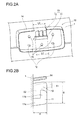
Fig. 2A is an enlarged explanatory diagram showing an overall perspective view of a stand mounting part; -
Fig. 2B is an enlarged explanatory diagram showing a side view of a main part in the stand mounting part; -
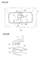
Fig. 3A is an enlarged explanatory diagram showing a plan view of a stand top; -
Fig. 3B is an enlarged explanatory diagram showing a cross-sectional perspective view of the stand top; -
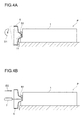
Fig. 4A is a general explanatory diagram showing a procedure of attaching a stand to a display unit in a temporarily fixed state, and -
Fig. 4B is a general explanatory diagram showing the procedure of attaching the stand to the display unit in a state fixed with a screw. - Now, an embodiment of the present invention will be described with reference to the drawings. It should be noted that the same components are designated by the same reference numbers, and detailed descriptions related to the components will be omitted as appropriate.
- A stand attachment structure according to this embodiment is, for example, as shown in
Fig. 1 , a structure for attaching astand 5 to a display unit P which includes aliquid crystal module 2, afront cabinet 3 and arear cabinet 1. With the stand attachment structure, thestand 5 is attached by fitting thestand 5 in astand mounting part 10 disposed on the display unit P, and anengagement tab 52 disposed on thestand 5 is engaged with ahook 11 disposed on thestand mounting part 10. - The
stand mounting part 10, which may be disposed on any site in a casing for constituting the display unit P, is disposed at a bottom of therear cabinet 1 in this embodiment. Accordingly, therear cabinet 1 including thestand mounting part 10, theliquid crystal module 2, thefront cabinet 3, and astand holder 4 are assembled to constitute the display unit P, and thestand 5 is attached to thestand mounting part 10 to form a display apparatus TV into a single unit. - The
stand 5 is composed of a base and astand top 51 protruding from the base. Thestand top 51, which is an attachment section to be fitted and attached to thestand mounting part 10 disposed on therear cabinet 1, is fitted in thestand mounting part 10 formed on a bottom surface of therear cabinet 1. Then, a set screw B1 is screwed into thestand holder 4 in order to co-fasten thestand 5 and therear cabinet 1. - Meanwhile, a temporarily fixed position is limited through engagement achieved by hooking the
engagement tab 52 provided to the stand top 51 on thehook 11 provided to thestand mounting part 10. In addition, theengagement tab 52 is engaged along a reinforcing rib 12 (refer toFig. 2 ) having both a function of reinforcing thehook 11 and a function of guiding theengagement tab 52 for its insertion, which allows thestand 5 to be attached easily and safely with the stand attachment structure. - Next, referring to
Fig. 2 , thestand mounting part 10 will be described in further detail. - As shown in
Fig. 2A , thestand mounting part 10, which is disposed on the bottom surface of therear cabinet 1, is formed into a concave shape or a shape surrounded by aperipheral wall rib 14. In addition, thestand mounting part 10 further includes a temporal fixing means 13 consisting of thehook 11 and the reinforcingrib 12, and also includes a plurality of first screw insertion holes 15 into which the set screws are inserted.Reference numeral 16 represents cylindrical guides used as positioning guides for fitting the above-describedstand top 51 of thestand 5. - As shown in
Fig. 2B , thehook 11 is formed, in cross section, into a shape of the letter L composed of a risingpiece 11 a protruded from a frame of therear cabinet 1 and abending piece 11b curved from an end of the risingpiece 11a. Thehook 11 has a function of retaining thestand 5 in a predetermined orientation through engagement achieved by hooking theengagement tab 52 provided to thestand 5 on thebending piece 11b. On the other hand, a plurality of the reinforcingribs 12 are arranged along a direction of a length L1 of thehook 11, and has both a function of reinforcing thehook 11 and a function of guiding theengagement tab 52 for its insertion. - In addition to provision of the plurality of reinforcing ribs 12 (for example, three reinforcing
ribs 12 as shown inFig. 2A ) arranged in the form of comb teeth along the length direction of thehook 11, a plurality of open slots 53 (refer toFig. 3A ) in which the reinforcingribs 12 can be inserted are disposed also in the form of comb teeth on theengagement tab 52 whose entire length is defined to be equal to the length of the hook. Consequently, theengagement tab 52 can be engaged with thehook 11 by fitting theopen slots 53 while causing theopen slots 53 to move along the reinforcingribs 12. - As such, when both the
engagement tabs 52 on a stand side and thehook 11 with the reinforcingribs 12 on a rear cabinet side are designed in the form of the comb teeth to be engaged with each other, theengagement tab 52 can be engaged with thehook 11 in a firmly hooked state while being guided. - On the other hand, a height H of the reinforcing
rib 12 is defined to be equal to the height of thehook 11, while a length E of the reinforcingrib 12 is defined at a level adequate to prevent a human finger from making access to thestand mounting part 10, in addition to arranging adjacent reinforcing ribs at an interval also adequate to prevent the human finger from making access thereto. With this structure, temporal fixing operation and screwing operation can be safely performed on the stand without a danger of causing the finger to be caught in a gap between the stand top where theengagement tab 52 is formed and thestand mounting part 10 or between thehook 11 and theengagement tab 52. - Meanwhile, the
peripheral wall rib 14 is designed to have a partial missing length L2. The missing length L2 is slightly greater than the length L1 of thehook 11. Thus, even though thehook 11 and the reinforcingribs 12 are provided in an inner region surrounded by theperipheral wall rib 14, an architecture to be integrally molded using upper and lower dies can be realized by designing theperipheral wall rib 14 so as to have a missing part of a length corresponding to the length L1 of thehook 11 in a region facing thehook 11 and the reinforcingribs 12. Consequently, therear cabinet 1 of a complicated geometry including thestand mounting part 10 can be manufactured with a resin molding as a single unit. - As has been described above, since the
rear cabinet 1 on which thestand mounting part 10 including the temporal fixing means 13 composed of thehook 11 and the reinforcingrib 12 is disposed is integrally moldable, it becomes possible to mass produce therear cabinet 1, which leads to reduction in cost of manufacturing therear cabinet 1. - Next, referring to
Fig. 3 , theengagement tab 52 will be described in further detail. - As shown in
Fig. 3A , theengagement tab 52 is shaped in the form of comb teeth with a large opening of ahook insertion part 54 and small openings of the plurality ofopen slots 53 formed at an end of thestand top 51. Thehook insertion part 54 is the opening larger than thehook 11, and thehook 11 can be inserted therethrough, thereby allowing thestand top 51 to be fitted in thestand mounting part 10. -
Reference numeral 55 represents second screw insertion holes which are communicating with the above-described first screw insertion holes 15 formed in thestand mounting part 10 when thestand 5 is temporarily fixed to thestand mounting part 10. As a result, the set screw B1 can be screwed passing through the first and second screw insertion holes 15 and 55 into a tapped hole of the above-describedstand holder 4, to thereby co-fasten thestand 5 and therear cabinet 1 to thestand holder 4. -
Reference numeral 56 represents guide holes into which the above-describedcylindrical guides 16 are inserted. Theguide hole 56 is formed in the shape of an elongated hole in order to facilitate insertion operation for engaging thehook 11 and theengagement tab 52 with each other. - In addition, strengthening
rib 57 is provided to an open edge of thehook insertion part 54 as shown in a cross sectional view ofFig. 3B (taken along a line III B - III B inFig. 3A ) in terms of increasing component strength in the vicinity of thehook insertion part 54 where a wide open area exists. - Thus, the
stand 5 can be attached by engaging theengagement tab 52 formed on thestand top 51 with thehook 11 in thestand mounting part 10 disposed on therear cabinet 1. On the other hand, since theengagement tab 52 is hooked on thehook 11, thestand 5 can be installed and temporarily fixed in the predetermined orientation to the display unit P in a condition where the display unit P is put into a sideways position. - The
stand 5, which is temporarily fixed, as described above, in the predetermined orientation through the temporal fixing means 13 composed of both thehook 11 and the reinforcingribs 12 to thestand mounting part 10 in therear cabinet 1, can be easily secured with screws after it is temporarily fixed. In addition, since the reinforcingrib 12 has the functions of reinforcing thehook 11 and of guiding theengagement tab 52 for insertion, the temporal fixing operation can be performed easily and safely while preventing thehook 11 from breakage. - For example, as shown in
Fig. 4A , the display unit P is laid down on a table. In this case, the display unit P is placed with therear cabinet 1 facing upward, so that thehook 11 is oriented in an up-pointing position. Operation of fitting thestand 5 in the display unit P is performed while turning thestand 5 along an operation path D1 indicated inFig. 4A , and theengagement tab 52 is accordingly engaged with thehook 11 to temporarily fix thestand 5. - In view of the fitting operation performed while turning the
stand 5 along the operation path D1, thestand top 51 is defined to become smaller than thestand mounting part 10, while theguide hole 56 is formed in the shape of the elongated hole in order to allow the thus-performed fitting operation. - Next, as shown in
Fig. 4B , the set screw B1 is screwed and firmly tightened using adriver 7 while pushing the set screw B1 along an arrow direction D2 in the drawing. Since the tapped hole into which the set screw B1 is screwed and tightened is formed in thestand holder 4 used for fastening the liquid crystal module and the front cabinet that constitute the display unit P, therear cabinet 1 and thestand 5 can be firmly fixed using the screw to thestand holder 4, which can ensure firm fixation of thestand 5 and the display unit P. - In the above-described stand attachment structure, including the engagement tab disposed on the stand top protruding from the base of the stand and the hook disposed on the stand mounting part in the rear cabinet, the engagement tab is engaged with the hook for temporal fixation, and the set screw is inserted from the second screw insertion hole on the stand side after the temporal fixation, and then, passing through the first screw insertion hole in the rear cabinet, screwed into the tapped hole of the rearward stand holder, to complete screw fixation.
- In this way, the stand can be temporarily fixed to the display unit P for a time, and the stand and the rear cabinet can be co-fastened and firmly fixed using the set screw after the temporal fixing. Further, a need to hold the display unit P or the stand with a hand during screwing operation can be eliminated. Accordingly, attachment can be easily implemented with the stand attachment structure.
- In the stand attachment structure configured as described above, the plurality of reinforcing ribs are disposed along the length direction of the hook in the form of comb teeth whose height is defined to be equal to the height of the hook and whose length is defined at a level adequate to prevent the human finger from making access to the stand mounting part, and the adjacent ones of the reinforcing ribs are arranged at the interval adequate to prevent the human finger from making access thereto. In addition, the open slots in which the reinforcing ribs can be inserted are also disposed in the form of comb teeth on the engagement tab whose entire length is defined to be equal to the length of the hook. With the thus-constructed stand attachment structure, the temporal fixing operation and screwing operation can be performed safely without the danger of causing the finger to be caught in the gap between the stand top and the stand mounting part or between the hook and the engagement tab.
- Further, since the stand mounting part is provided with the peripheral wall rib which surrounds the edge of the stand mounting part and the peripheral wall rib has the missing part of the length corresponding to the length of the hook in the region facing the reinforcing rib, and accordingly the stand mounting part is constructed as the resin molding in which the peripheral wall rib, the hook, and the reinforcing rib are integrally formed, the rear cabinet, in which the hook including the reinforcing rib is disposed on the stand mounting part including the peripheral wall rib, can be mass-manufactured, which can contributes to reduction in manufacturing costs.
- Moreover, since the stand mounting part is provided to the rear cabinet in this embodiment, the stand can be temporarily fixed in the predetermined orientation to the stand mounting part in the rear cabinet through the temporal fixing means composed of the hook and the reinforcing ribs. In addition, final fixation of the stand can be completed with ease and reliability by securing the stand with the screw after the temporal fixing. Further, since the reinforcing rib has the functions of reinforcing the hook and of guiding the engagement tab for insertion, it is possible to perform the temporal fixing operation easily and safely while preventing the hook from breakage.
- Furthermore, the reinforcing ribs are arranged in the form of the comb teeth on the hook in order to further firmly reinforce the hook and allow protection of the finger from an incident that the finger is caught in the gap between the stand top and the stand mounting part or between the hook and the engagement tab, which can ensure safety in temporal fixing operation and screwing operation.
- Although both the stand attachment structure for mounting the stand to the display unit including the liquid crystal module and the rear cabinet including the stand mounting part have been described above, the stand attachment structure according to the present invention may be applied to attaching a stand to a display unit equipped with any display screen other than the liquid crystal module. Alternatively, the stand attachment structure according to the present invention may be applied to any unit other than the display unit as long as the unit has construction obtained by assembling a main body and a stand.
- As has been described above, according to the stand attachment structure of the present invention, the stand mounting part including the temporal fixing means composed of the hook and the reinforcing rib is disposed on the display unit, while the engagement tab is disposed on the stand. Then, the stand is temporarily fixed to the display unit by engaging the engagement tab with the hook, and, after the temporal fixation, finally secured to the display unit with the set screw, which can contribute to implementation of easy and reliable temporal fixing and screwing operation. Consequently, the stand attachment structure with which the stand can be attached with ease and safe can be obtained.
- Further, according to the rear cabinet of the present invention, since the temporal fixing means composed of both the hook on which the engagement tab disposed on the stand is hooked to retain the stand in the predetermined orientation and the reinforcing rib having the functions of reinforcing the hook and of guiding the engagement tab for insertion is formed on the stand mounting part, the temporal fixing operation and the screwing operation can be performed easily and reliably. In this way, the rear cabinet to which the stand can be attached readily and safely can be obtained.
- Thus, the stand attachment structure and the rear cabinet according to the present invention may be preferably applied to a display apparatus of such a type that a display unit and a stand are separately packed, and a user who has purchased the display apparatus needs to assemble the display unit and the stand by himself/herself.
-
- 1: Rear cabinet
- 2: Liquid crystal module
- 3: Front cabinet
- 4: Stand holder
- 5: Stand
- 10: Stand mounting part
- 11: Hook
- 12: Reinforcing rib
- 13: Temporal fixing means
- 14: Peripheral wall rib
- 15: First screw insertion hole
- 16: Cylindrical guide
- 51: Stand top
- 52: Engagement tab
- 53: Open slot
- 54: Hook insertion part
- 55: Second screw insertion hole
Claims (8)
- A stand attachment structure for attaching a stand to a display unit incorporating a liquid crystal module, a front cabinet, and a rear cabinet, characterized in that:the display unit includes a stand attachment part provided with a temporal fixing means which is composed of a hook for retaining the stand in a predetermined orientation and a reinforcing rib having functions of reinforcing the hook and of guiding an engagement tab formed on the stand for insertion;the stand is equipped with the engagement tab to be engaged with the hook; andthe stand is temporarily fixed to the display unit by engaging the engagement tab to the hook, and then finally fixed to the display unit with a set screw after the temporal fixing.
- The stand attachment structure according to Claim 1, wherein:in addition to the temporal fixing means, a first screw insertion hole is formed in the stand mounting part;the stand has a base and a stand top protruding from the base, the stand top where a hook insertion part in which the hook can be inserted and a second screw insertion hole communicating with the first screw insertion hole are disposed in addition to the engagement tab, andthe stand top is fitted and temporarily fixed to the stand mounting part by engaging the engagement tab with the hook, and then finally secured with the set screw inserted through the first and second screw insertion holes after the temporal fixing.
- The stand attachment structure according to Claim 1 or 2, wherein:a plurality of reinforcing ribs are disposed along a direction of length of the hook in a form of comb teeth whose height is defined to be equal to the height of the hook and whose length is defined at a level adequate to prevent a human finger from making access to the stand mounting part, while adjacent ones of the reinforcement ribs are arranged at an interval adequate to prevent the human finger from making access thereto, andopen slots in which the reinforcing ribs can be inserted are arranged in the form of comb teeth on the engagement tab whose entire length is defined to be equal to the length of the hook.
- The stand attachment structure according to Claim 3, wherein:the engagement tab is engaged with the hook by attaching the stand to the stand mounting part while causing the open slots to move along the reinforcing ribs.
- The stand attachment structure according to any one of Claims 2 to 4, wherein:the stand mounting part is disposed at a bottom of the rear cabinet;a stand holder having a tapped hole which communicates with the first screw insertion hole is disposed inside the unit on the stand mounting part, andthe stand and the rear cabinet are co-fastened to the stand holder through the set screw for final fixation.
- A rear cabinet for retaining a liquid crystal module in conjunction with a front cabinet to constitute a display unit, comprising:a stand mounting part to which a stand for supporting the display unit in an upright position is attached, anda temporal fixing means disposed on the stand mounting part to temporarily fix the stand at a predetermined position in a predetermined orientation, and composed of both a hook to which an engagement tab disposed on the stand is hooked to retain the stand in the predetermined orientation, and a reinforcing rib which has functions of reinforcing the hook and of guiding the engagement tab for insertion.
- The rear cabinet according to Claim 6, wherein:the stand mounting part includes a peripheral wall rib surrounding an edge of the stand mounting part, the peripheral wall rib being configured to have a missing part of a length corresponding to a length of the hook in a region facing the reinforcing rib, thereby allowing the stand mounting part to be formed as a resin molding in which the peripheral wall rib, the hook, and the reinforcing rib are integrally molded.
- The rear cabinet according to Claim 6 or 7, wherein:a plurality of the reinforcing ribs are disposed along a direction of length of the hook in a form of comb teeth whose height is defined to be equal to the height of the hook, and whose length is defined at a level adequate to prevent a human finger from making access to the stand mounting part, while adjacent ones of the reinforcing ribs are arranged at an interval adequate to prevent the human finger from making access thereto.
Applications Claiming Priority (1)
| Application Number | Priority Date | Filing Date | Title |
|---|---|---|---|
| JP2009171785A JP5251771B2 (en) | 2009-07-23 | 2009-07-23 | Stand mounting structure and rear cabinet |
Publications (2)
| Publication Number | Publication Date |
|---|---|
| EP2278207A2 true EP2278207A2 (en) | 2011-01-26 |
| EP2278207A3 EP2278207A3 (en) | 2012-10-17 |
Family
ID=42829925
Family Applications (1)
| Application Number | Title | Priority Date | Filing Date |
|---|---|---|---|
| EP10170445A Withdrawn EP2278207A3 (en) | 2009-07-23 | 2010-07-22 | Stand mounting structure and rear cabinet |
Country Status (3)
| Country | Link |
|---|---|
| US (1) | US8967559B2 (en) |
| EP (1) | EP2278207A3 (en) |
| JP (1) | JP5251771B2 (en) |
Cited By (1)
| Publication number | Priority date | Publication date | Assignee | Title |
|---|---|---|---|---|
| CN111853487A (en) * | 2020-07-28 | 2020-10-30 | 海信视像科技股份有限公司 | A support frame, base and display device |
Families Citing this family (5)
| Publication number | Priority date | Publication date | Assignee | Title |
|---|---|---|---|---|
| CN102654959B (en) * | 2011-03-04 | 2014-06-04 | 瑞轩科技股份有限公司 | Display housing and its frame structure |
| JP5281212B1 (en) * | 2012-05-18 | 2013-09-04 | シャープ株式会社 | Display device and television receiver |
| JP6602058B2 (en) * | 2015-06-05 | 2019-11-06 | シャープ株式会社 | Display device and television receiver |
| KR102719268B1 (en) * | 2019-04-08 | 2024-10-21 | 엘지전자 주식회사 | Display device |
| KR20230100423A (en) * | 2021-12-28 | 2023-07-05 | 삼성전자주식회사 | Display apparatus |
Citations (2)
| Publication number | Priority date | Publication date | Assignee | Title |
|---|---|---|---|---|
| JP2006173849A (en) | 2004-12-14 | 2006-06-29 | Funai Electric Co Ltd | Liquid crystal television receiver and display device |
| JP2009038540A (en) | 2007-08-01 | 2009-02-19 | Funai Electric Co Ltd | Television receiver with stand |
Family Cites Families (33)
| Publication number | Priority date | Publication date | Assignee | Title |
|---|---|---|---|---|
| JPS6146307U (en) * | 1984-08-28 | 1986-03-27 | 松下精工株式会社 | stand mounting device |
| JPH048454Y2 (en) * | 1985-06-18 | 1992-03-03 | ||
| JPH0810723Y2 (en) | 1987-12-29 | 1996-03-29 | 日本建鐵株式会社 | Fixed structure of machine box and stand |
| US4898493A (en) * | 1989-03-16 | 1990-02-06 | Karl Blankenburg | Method and apparatus for assembling parts |
| JP3348219B2 (en) * | 1995-05-17 | 2002-11-20 | 株式会社ナナオ | Auxiliary case for video monitor |
| JPH10299729A (en) * | 1997-04-23 | 1998-11-10 | Mitsubishi Electric Corp | Assembling stand |
| TW430093U (en) * | 1999-05-28 | 2001-04-11 | Twinhead Int Corp | Integrated structure of thin display apparatus |
| TW580228U (en) * | 2001-03-21 | 2004-03-11 | Benq Corp | Carrying structure |
| KR100443981B1 (en) * | 2001-12-04 | 2004-08-09 | 삼성전자주식회사 | Monitor |
| JP3901501B2 (en) * | 2001-12-12 | 2007-04-04 | アルプス電気株式会社 | Electronic circuit unit mounting structure |
| US7175144B2 (en) * | 2002-06-18 | 2007-02-13 | Benq Corporation | Detachable base support |
| KR100475567B1 (en) * | 2002-09-13 | 2005-03-10 | 삼성전자주식회사 | display apparatus |
| JP4065752B2 (en) * | 2002-10-04 | 2008-03-26 | シャープ株式会社 | Flat panel display packing equipment |
| TWI223740B (en) * | 2003-11-06 | 2004-11-11 | Benq Corp | Combined supporting base |
| JP2005221823A (en) * | 2004-02-06 | 2005-08-18 | Toshiba Corp | Display device |
| JP3110945U (en) * | 2005-03-02 | 2005-07-07 | 船井電機株式会社 | Liquid crystal display |
| TWM284184U (en) * | 2005-06-24 | 2005-12-21 | Innolux Display Corp | Liquid crystal display device |
| US7361046B2 (en) * | 2005-07-01 | 2008-04-22 | Hewlett-Packard Development Company, L.P. | Display assembly |
| KR100702235B1 (en) * | 2005-07-11 | 2007-04-03 | 삼성전자주식회사 | Display device |
| JP3116087U (en) * | 2005-08-25 | 2005-11-24 | 船井電機株式会社 | LCD television |
| JP2007086625A (en) * | 2005-09-26 | 2007-04-05 | Sharp Corp | Display device |
| TWI259047B (en) * | 2005-09-30 | 2006-07-21 | Techview Internat Technology I | Detachable pedestal |
| KR100776420B1 (en) * | 2005-11-14 | 2007-11-16 | 엘지전자 주식회사 | Stand for visual display device |
| JP2007235692A (en) * | 2006-03-02 | 2007-09-13 | Funai Electric Co Ltd | Liquid crystal television and stand structure for liquid crystal display device |
| KR101169278B1 (en) * | 2006-06-20 | 2012-08-02 | 엘지전자 주식회사 | Monitor device |
| TW200817765A (en) * | 2006-10-11 | 2008-04-16 | Innolux Display Corp | Liquid crystal display device |
| JP2008124708A (en) * | 2006-11-10 | 2008-05-29 | Sharp Corp | Thin display platform |
| JP5019582B2 (en) * | 2007-01-31 | 2012-09-05 | 株式会社東芝 | Display device |
| JP2008213908A (en) * | 2007-03-06 | 2008-09-18 | Funai Electric Co Ltd | Packaging structure of plasma display and packaging structure of thin television |
| JP2008275824A (en) * | 2007-04-27 | 2008-11-13 | Sharp Corp | Thin display device and assembly method of housing structure |
| US7819372B2 (en) * | 2008-02-20 | 2010-10-26 | Hannspree, Inc. | Display and detachable base assembly thereof |
| TWM347001U (en) * | 2008-07-16 | 2008-12-11 | Amtran Technology Co Ltd | Base |
| CN201336114Y (en) * | 2008-11-25 | 2009-10-28 | 鸿富锦精密工业(深圳)有限公司 | Display device |
-
2009
- 2009-07-23 JP JP2009171785A patent/JP5251771B2/en not_active Expired - Fee Related
-
2010
- 2010-07-22 US US12/841,542 patent/US8967559B2/en not_active Expired - Fee Related
- 2010-07-22 EP EP10170445A patent/EP2278207A3/en not_active Withdrawn
Patent Citations (2)
| Publication number | Priority date | Publication date | Assignee | Title |
|---|---|---|---|---|
| JP2006173849A (en) | 2004-12-14 | 2006-06-29 | Funai Electric Co Ltd | Liquid crystal television receiver and display device |
| JP2009038540A (en) | 2007-08-01 | 2009-02-19 | Funai Electric Co Ltd | Television receiver with stand |
Cited By (1)
| Publication number | Priority date | Publication date | Assignee | Title |
|---|---|---|---|---|
| CN111853487A (en) * | 2020-07-28 | 2020-10-30 | 海信视像科技股份有限公司 | A support frame, base and display device |
Also Published As
| Publication number | Publication date |
|---|---|
| JP2011027872A (en) | 2011-02-10 |
| JP5251771B2 (en) | 2013-07-31 |
| US20110043980A1 (en) | 2011-02-24 |
| US8967559B2 (en) | 2015-03-03 |
| EP2278207A3 (en) | 2012-10-17 |
Similar Documents
| Publication | Publication Date | Title |
|---|---|---|
| US8967559B2 (en) | Stand mounting structure and rear cabinet | |
| US8437120B2 (en) | Image display device | |
| US7002792B2 (en) | Structure for mounting flat display module and method thereof | |
| KR100786738B1 (en) | Rack system, adapter, rack frame, support rail, and method of making a rack system | |
| US8482907B2 (en) | Electronic device and wall hanging structure of electronic device | |
| EP2330457A2 (en) | Display apparatus | |
| KR20040036407A (en) | Device for fixing to module of LCD monitor | |
| JP2011123269A (en) | Display device | |
| EP2565743A2 (en) | Display device and television device | |
| US20130222996A1 (en) | System for mounting appliances behind a flat panel display | |
| EP2497993A2 (en) | Cabinet structure assembly | |
| EP2587110A2 (en) | Display apparatus | |
| JP2005197421A (en) | Electronic apparatus | |
| KR20090023124A (en) | Plasma display device | |
| US20030122994A1 (en) | Liquid crystal display with a changeable front frame | |
| KR20090074665A (en) | Structure of coupling between front cover and frame in display device | |
| US20110205455A1 (en) | Television Set | |
| EP4539620A1 (en) | Integrated fastening structure and electronic device comprising same | |
| CN210670894U (en) | Display shell and display device | |
| CN211428877U (en) | Cable management device for medical equipment lifting structure and medical equipment | |
| CN114352164B (en) | Door body of electric appliance and electric appliance | |
| JP2005019805A (en) | Housing structure | |
| CN115192351B (en) | Medical instrument and medical system | |
| JPS584373Y2 (en) | Control plate mounting mechanism | |
| JP2011019171A (en) | Temporary fixation structure of speaker holder |
Legal Events
| Date | Code | Title | Description |
|---|---|---|---|
| PUAI | Public reference made under article 153(3) epc to a published international application that has entered the european phase |
Free format text: ORIGINAL CODE: 0009012 |
|
| AK | Designated contracting states |
Kind code of ref document: A2 Designated state(s): AL AT BE BG CH CY CZ DE DK EE ES FI FR GB GR HR HU IE IS IT LI LT LU LV MC MK MT NL NO PL PT RO SE SI SK SM TR |
|
| AX | Request for extension of the european patent |
Extension state: BA ME RS |
|
| PUAL | Search report despatched |
Free format text: ORIGINAL CODE: 0009013 |
|
| AK | Designated contracting states |
Kind code of ref document: A3 Designated state(s): AL AT BE BG CH CY CZ DE DK EE ES FI FR GB GR HR HU IE IS IT LI LT LU LV MC MK MT NL NO PL PT RO SE SI SK SM TR |
|
| AX | Request for extension of the european patent |
Extension state: BA ME RS |
|
| RIC1 | Information provided on ipc code assigned before grant |
Ipc: F16M 11/16 20060101ALN20120913BHEP Ipc: F16M 11/04 20060101ALI20120913BHEP Ipc: F16M 11/22 20060101AFI20120913BHEP |
|
| 17P | Request for examination filed |
Effective date: 20130412 |
|
| 17Q | First examination report despatched |
Effective date: 20140313 |
|
| RIC1 | Information provided on ipc code assigned before grant |
Ipc: F16M 11/16 20060101ALN20170323BHEP Ipc: F16M 11/22 20060101AFI20170323BHEP Ipc: F16M 11/04 20060101ALI20170323BHEP |
|
| GRAP | Despatch of communication of intention to grant a patent |
Free format text: ORIGINAL CODE: EPIDOSNIGR1 |
|
| INTG | Intention to grant announced |
Effective date: 20170602 |
|
| STAA | Information on the status of an ep patent application or granted ep patent |
Free format text: STATUS: THE APPLICATION IS DEEMED TO BE WITHDRAWN |
|
| 18D | Application deemed to be withdrawn |
Effective date: 20171013 |