JP5019582B2 - Display device - Google Patents

Display device Download PDF

Info

Publication number
JP5019582B2
JP5019582B2 JP2007022070A JP2007022070A JP5019582B2 JP 5019582 B2 JP5019582 B2 JP 5019582B2 JP 2007022070 A JP2007022070 A JP 2007022070A JP 2007022070 A JP2007022070 A JP 2007022070A JP 5019582 B2 JP5019582 B2 JP 5019582B2
Authority
JP
Japan
Prior art keywords
pin
opening
main body
stand
cam
Prior art date
Legal status (The legal status is an assumption and is not a legal conclusion. Google has not performed a legal analysis and makes no representation as to the accuracy of the status listed.)
Expired - Fee Related
Application number
JP2007022070A
Other languages
Japanese (ja)
Other versions
JP2008186003A (en
JP2008186003A5 (en
Inventor
充良 高尾
Current Assignee (The listed assignees may be inaccurate. Google has not performed a legal analysis and makes no representation or warranty as to the accuracy of the list.)
Toshiba Corp
Original Assignee
Toshiba Corp
Priority date (The priority date is an assumption and is not a legal conclusion. Google has not performed a legal analysis and makes no representation as to the accuracy of the date listed.)
Filing date
Publication date
Application filed by Toshiba Corp filed Critical Toshiba Corp
Priority to JP2007022070A priority Critical patent/JP5019582B2/en
Priority to US12/021,073 priority patent/US7686271B2/en
Publication of JP2008186003A publication Critical patent/JP2008186003A/en
Publication of JP2008186003A5 publication Critical patent/JP2008186003A5/ja
Application granted granted Critical
Publication of JP5019582B2 publication Critical patent/JP5019582B2/en
Expired - Fee Related legal-status Critical Current
Anticipated expiration legal-status Critical

Links

Images

Classifications

    • FMECHANICAL ENGINEERING; LIGHTING; HEATING; WEAPONS; BLASTING
    • F16ENGINEERING ELEMENTS AND UNITS; GENERAL MEASURES FOR PRODUCING AND MAINTAINING EFFECTIVE FUNCTIONING OF MACHINES OR INSTALLATIONS; THERMAL INSULATION IN GENERAL
    • F16MFRAMES, CASINGS OR BEDS OF ENGINES, MACHINES OR APPARATUS, NOT SPECIFIC TO ENGINES, MACHINES OR APPARATUS PROVIDED FOR ELSEWHERE; STANDS; SUPPORTS
    • F16M11/00Stands or trestles as supports for apparatus or articles placed thereon ; Stands for scientific apparatus such as gravitational force meters
    • F16M11/20Undercarriages with or without wheels
    • F16M11/22Undercarriages with or without wheels with approximately constant height, e.g. with constant length of column or of legs
    • FMECHANICAL ENGINEERING; LIGHTING; HEATING; WEAPONS; BLASTING
    • F16ENGINEERING ELEMENTS AND UNITS; GENERAL MEASURES FOR PRODUCING AND MAINTAINING EFFECTIVE FUNCTIONING OF MACHINES OR INSTALLATIONS; THERMAL INSULATION IN GENERAL
    • F16MFRAMES, CASINGS OR BEDS OF ENGINES, MACHINES OR APPARATUS, NOT SPECIFIC TO ENGINES, MACHINES OR APPARATUS PROVIDED FOR ELSEWHERE; STANDS; SUPPORTS
    • F16M11/00Stands or trestles as supports for apparatus or articles placed thereon ; Stands for scientific apparatus such as gravitational force meters
    • F16M11/02Heads
    • F16M11/04Means for attachment of apparatus; Means allowing adjustment of the apparatus relatively to the stand
    • F16M11/06Means for attachment of apparatus; Means allowing adjustment of the apparatus relatively to the stand allowing pivoting
    • F16M11/10Means for attachment of apparatus; Means allowing adjustment of the apparatus relatively to the stand allowing pivoting around a horizontal axis
    • F16M11/105Means for attachment of apparatus; Means allowing adjustment of the apparatus relatively to the stand allowing pivoting around a horizontal axis the horizontal axis being the roll axis, e.g. for creating a landscape-portrait rotation
    • FMECHANICAL ENGINEERING; LIGHTING; HEATING; WEAPONS; BLASTING
    • F16ENGINEERING ELEMENTS AND UNITS; GENERAL MEASURES FOR PRODUCING AND MAINTAINING EFFECTIVE FUNCTIONING OF MACHINES OR INSTALLATIONS; THERMAL INSULATION IN GENERAL
    • F16MFRAMES, CASINGS OR BEDS OF ENGINES, MACHINES OR APPARATUS, NOT SPECIFIC TO ENGINES, MACHINES OR APPARATUS PROVIDED FOR ELSEWHERE; STANDS; SUPPORTS
    • F16M2200/00Details of stands or supports
    • F16M2200/08Foot or support base
    • YGENERAL TAGGING OF NEW TECHNOLOGICAL DEVELOPMENTS; GENERAL TAGGING OF CROSS-SECTIONAL TECHNOLOGIES SPANNING OVER SEVERAL SECTIONS OF THE IPC; TECHNICAL SUBJECTS COVERED BY FORMER USPC CROSS-REFERENCE ART COLLECTIONS [XRACs] AND DIGESTS
    • Y10TECHNICAL SUBJECTS COVERED BY FORMER USPC
    • Y10STECHNICAL SUBJECTS COVERED BY FORMER USPC CROSS-REFERENCE ART COLLECTIONS [XRACs] AND DIGESTS
    • Y10S248/00Supports
    • Y10S248/917Video display screen support
    • Y10S248/919Adjustably orientable video screen support
    • Y10S248/922Angular
    • Y10S248/923Tilting

Landscapes

  • Engineering & Computer Science (AREA)
  • General Engineering & Computer Science (AREA)
  • Mechanical Engineering (AREA)
  • Devices For Indicating Variable Information By Combining Individual Elements (AREA)

Description

本発明は、本体の傾きを調整することができる表示装置に関する。   The present invention relates to a display device capable of adjusting a tilt of a main body.

例えば、表示画面を水平に保つための調整機構を備えた薄型表示装置として、以下のものが開示されている。この薄型表示装置は、画面部と、画面部を支持するスタンドと、画面部とスタンドとを取り付けるための取り付け部材と、を備えている。取り付け部材は、画面部とスタンドとを位置決めする位置決めピンと、画面部とスタンドとをねじ止めする固定孔と、画面部とスタンドとの取り付け位置を調整する位置調整孔と、を含んでいる。薄型表示装置は、さらに偏心カムを備えている。この偏心カムを支持している構造の詳細は不明である。   For example, the following is disclosed as a thin display device provided with an adjustment mechanism for keeping the display screen horizontal. This thin display device includes a screen portion, a stand that supports the screen portion, and an attachment member for attaching the screen portion and the stand. The attachment member includes a positioning pin for positioning the screen portion and the stand, a fixing hole for screwing the screen portion and the stand, and a position adjustment hole for adjusting the attachment position of the screen portion and the stand. The thin display device further includes an eccentric cam. Details of the structure supporting the eccentric cam are unknown.

この薄型表示装置では、位置決めピンを介して画面部とスタンドとの間でおよその位置を決定する。そして、位置調整孔に偏心カムを挿入し、偏心カムを回転させることにより、スタンドに対して画面部を回転させる。このとき、画面部は、固定孔に止められたねじを支点に回転することができる(例えば、特許文献1参照)。
特開2004−112234号公報
In this thin display device, an approximate position is determined between the screen unit and the stand via the positioning pin. Then, the eccentric cam is inserted into the position adjustment hole, and the eccentric cam is rotated to rotate the screen portion with respect to the stand. At this time, the screen part can be rotated with a screw fixed to the fixing hole as a fulcrum (see, for example, Patent Document 1).
JP 2004-112234 A

しかしながら、上記従来の薄型表示装置では、位置決めピンで画面部の大体の位置を決めた後、偏心カムを介して画面部を回転させるようにしているため、画面部の回転量が十分にとれないおそれがあった。また、一般にねじ止め用の固定孔は、公差などを考慮して遊びをもって形成されることが多い。このため、ねじを支点として画面部を回転させると、支点軸となるねじ自体が上下動することが考えられ、支点軸を中心に十分な回転量が得られないおそれがある。さらに、前記従来の薄型表示装置の構造では、偏心カムを回転させる際に、画面部の重量が偏心カムにかかることになるが、偏心カムの回転を助けるための手当てが何らなされていない問題があった。   However, in the conventional thin display device, since the screen portion is rotated via the eccentric cam after the position of the screen portion is roughly determined by the positioning pin, the amount of rotation of the screen portion is not sufficient. There was a fear. In general, the fixing holes for screwing are often formed with play in consideration of tolerances. For this reason, when the screen portion is rotated using the screw as a fulcrum, it is considered that the screw itself serving as the fulcrum shaft moves up and down, and a sufficient amount of rotation may not be obtained around the fulcrum shaft. Further, in the structure of the conventional thin display device, when the eccentric cam is rotated, the weight of the screen portion is applied to the eccentric cam. there were.

本発明の目的は、簡単な構造で、本体の十分な回転量を得ることができる表示装置を提供することにある。   An object of the present invention is to provide a display device that can obtain a sufficient amount of rotation of a main body with a simple structure.

前記目的を達成するため、本発明の一つの形態に係る表示装置は、本体と、前記本体を支持するスタンドと、前記本体と前記スタンドとの間に設けられるとともに、前記本体の傾きを調整できる調整機構と、を具備し、前記調整機構は、前記本体および前記スタンドのいずれか一方に設けられた第1の軸受部と、前記第1の軸受部に通されるとともに、軸方向に進退可能な第1のピンと、前記本体および前記スタンドの他方に設けられるとともに前記第1のピンが嵌められる第1の開口部と、前記第1のピンの中心軸と同心になるように前記第1のピンに設けられ、前記中心軸まわりに回転しつつ前記第1の開口部に嵌ったり、前記第1の開口部から外れたりする第1のカム部と、前記本体および前記スタンドのいずれか一方に設けられた第2の軸受部と、前記第2の軸受部に通されるとともに、軸方向に進退可能な第2のピンと、前記本体および前記スタンドの他方に設けられるとともに前記第2のピンが嵌められる第2の開口部と、前記第2のピンの中心軸に対して偏心するように前記第2のピンに設けられ、前記中心軸まわりに回転しつつ前記第2の開口部に嵌ったり、前記第2の開口部から外れたりする第2のカム部と、を有する。 In order to achieve the above object, a display device according to an embodiment of the present invention is provided between a main body, a stand that supports the main body, the main body and the stand, and can adjust an inclination of the main body. An adjusting mechanism, and the adjusting mechanism is passed through the first bearing portion provided in one of the main body and the stand and the first bearing portion, and can advance and retreat in the axial direction. A first opening provided on the other of the main body and the stand and fitted with the first pin, and the first pin so as to be concentric with a central axis of the first pin. A first cam portion that is provided on the pin and fits into the first opening while rotating around the central axis, or is detached from the first opening, and either the main body or the stand. Established And a second pin that is passed through the second bearing portion and is capable of moving forward and backward in the axial direction, and a second pin that is provided on the other of the main body and the stand and on which the second pin is fitted. An opening is provided on the second pin so as to be eccentric with respect to the central axis of the second pin, and is fitted around the second opening while rotating around the central axis. And a second cam portion that is disengaged from the opening .

本発明によれば、簡単な構造で、本体の十分な回転量を得ることができる表示装置を提供できる。   According to the present invention, it is possible to provide a display device capable of obtaining a sufficient amount of rotation of the main body with a simple structure.

以下に、図1から図9を参照して、表示装置の一例である薄型テレビの実施形態について説明する。   Hereinafter, an embodiment of a flat-screen television which is an example of a display device will be described with reference to FIGS. 1 to 9.

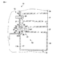
図1から図3に示すように、薄型テレビ11は、本体12と、本体12を支持するスタンド13と、本体12とスタンド13との間に設けられるとともに、本体12の傾きを調整できる調整機構14と、スタンド13に本体12を固定する際に本体12を仮止めするためのフック機構15と、を備えている。スタンド13は、弓形形状をなした脚部16と、脚部16から延びて本体12が取り付けられる固定部17と、固定部17を水平方向に回転できるように支持するヒンジ機構18と、を有している。フック機構15は、鉤形状をなして、左右一対に設けられている。固定部17は、例えば、厚さ3mmの金属板を曲げ加工して形成されている。   As shown in FIGS. 1 to 3, the thin television 11 is provided between the main body 12, a stand 13 that supports the main body 12, and the main body 12 and the stand 13, and an adjustment mechanism that can adjust the inclination of the main body 12. 14 and a hook mechanism 15 for temporarily fixing the main body 12 when the main body 12 is fixed to the stand 13. The stand 13 includes a leg portion 16 having an arcuate shape, a fixing portion 17 extending from the leg portion 16 to which the main body 12 is attached, and a hinge mechanism 18 that supports the fixing portion 17 so as to be able to rotate in the horizontal direction. is doing. The hook mechanism 15 has a hook shape and is provided in a pair of left and right. For example, the fixing portion 17 is formed by bending a metal plate having a thickness of 3 mm.

本体12は、フレーム21と、フレーム21に取り付けられた液晶パネル22と、液晶パネル22を駆動するための図示しない回路基板と、これらを囲む筐体23と、筐体23に設けられたスピーカ24と、を有している。フレーム21は、例えば厚さ2mmの金属板をプレス加工して形成されている。筐体23は、前面カバー25と、背面カバー26とを含んでいる。背面カバー26は、開口27を複数有している。この複数の開口27は、第1の位置決め部31の第1のピン34と、第2の位置決め部32の第2のピン44と、本体12とスタンド13とを固定するための複数のねじ28と、をそれぞれ外部に露出させている。言い換えると、背面カバー26は、第1の位置決め部31と、第2の位置決め部32と、複数のねじ28と、から外れて配置されている。   The main body 12 includes a frame 21, a liquid crystal panel 22 attached to the frame 21, a circuit board (not shown) for driving the liquid crystal panel 22, a casing 23 surrounding them, and a speaker 24 provided on the casing 23. And have. The frame 21 is formed by, for example, pressing a metal plate having a thickness of 2 mm. The housing 23 includes a front cover 25 and a back cover 26. The back cover 26 has a plurality of openings 27. The plurality of openings 27 include a plurality of screws 28 for fixing the first pin 34 of the first positioning portion 31, the second pin 44 of the second positioning portion 32, and the main body 12 and the stand 13. Are exposed to the outside. In other words, the back cover 26 is disposed away from the first positioning portion 31, the second positioning portion 32, and the plurality of screws 28.

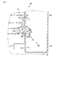
図9に示すように、調整機構14は、スタンド13に対して本体12を位置決めするための第1の位置決め部31と、第1の位置決め部31を支点に本体12をスタンド13に対して所定角度回転させる第2の位置決め部32と、を有している。   As shown in FIG. 9, the adjustment mechanism 14 has a first positioning portion 31 for positioning the main body 12 with respect to the stand 13, and the main body 12 with respect to the stand 13 with the first positioning portion 31 as a fulcrum. And a second positioning portion 32 that rotates the angle.

図4と図6に示すように、第1の位置決め部31は、スタンド13の固定部17に設けられた第1の軸受部33と、第1の軸受部33に通される第1のピン34と、本体12のフレーム21に設けられる第1の開口部35と、第1の軸受部33と第1のピン34との間に設けられた第1のねじ機構36と、第1の軸受部33の周囲に形成された第1の凹部37と、を有している。第1の軸受部33は、ねじ孔であり、その内周に雌ねじが形成されている。第1の軸受部33に対して、第1のピン34の第1のねじ部34Aを螺合させることができる。   As shown in FIGS. 4 and 6, the first positioning portion 31 includes a first bearing portion 33 provided in the fixing portion 17 of the stand 13 and a first pin that is passed through the first bearing portion 33. 34, a first opening 35 provided in the frame 21 of the main body 12, a first screw mechanism 36 provided between the first bearing portion 33 and the first pin 34, and a first bearing. And a first recess 37 formed around the portion 33. The 1st bearing part 33 is a screw hole, and the internal thread is formed in the inner periphery. The first screw portion 34 </ b> A of the first pin 34 can be screwed into the first bearing portion 33.

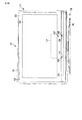
図6に示すように、第1の開口部35は、長孔形状に形成されている。第1の開口部35は、左右方向(水平方向)の寸法が大きくなっている。第1の開口部35は、後述するように偏心した第2のカム部44Bが回転した際に、第1の位置決め部31と第2の位置決め部32との間のピッチの変動を許容できる。第1の開口部35の縦方向の寸法は、第1のピン34の第1のカム部34Bに対して、若干のクリアランスがあるものの、第1のカム部34Bとほぼ同じ直径に形成されている。このため、第1のカム部34Bは、第1の開口部35に対して、上下方向においてきっちりと嵌るとともに、左右方向に移動することができる。なお、本実施形態では、第1の開口部35は、長孔(貫通孔)で構成されているが、これに限定されるものではなく、例えばフレーム21を貫通しない凹部などで構成してもよい。   As shown in FIG. 6, the first opening 35 is formed in a long hole shape. The first opening 35 has a large size in the left-right direction (horizontal direction). The first opening 35 can allow a variation in pitch between the first positioning portion 31 and the second positioning portion 32 when the eccentric second cam portion 44B rotates as will be described later. The vertical dimension of the first opening 35 is formed to be approximately the same diameter as the first cam portion 34B, although there is a slight clearance with respect to the first cam portion 34B of the first pin 34. Yes. For this reason, the first cam portion 34 </ b> B can fit in the vertical direction with respect to the first opening 35 and can move in the horizontal direction. In the present embodiment, the first opening 35 is configured by a long hole (through hole), but is not limited thereto, and may be configured by, for example, a recess that does not penetrate the frame 21. Good.

図7に示すように、第1のピン34は、第1のねじ部34Aと、第1のねじ部34Aの一方の端部に設けられた第1のカム部34Bと、第1のねじ部34Aの他方の端部に設けられた第1の軸部34Cと、第1のねじ部34Aと第1の軸部34Cとの間に設けられた第1の止め具34Dと、を含んでいる。第1のねじ部34Aは、第1の軸受部33に相補的な雄ねじで構成されている。第1のピン34は、第1のねじ機構36によって第1の軸受部33に対して軸方向に進退することができる。第1のカム部34Bおよび第1の止め具34Dは、第1の抜け止め部38を構成している。第1の抜け止め部38によって、第1のピン34は、進退する際に第1の軸受部33から脱落しないようになっている。   As shown in FIG. 7, the first pin 34 includes a first screw portion 34A, a first cam portion 34B provided at one end of the first screw portion 34A, and a first screw portion. A first shaft portion 34C provided at the other end portion of 34A, and a first stopper 34D provided between the first screw portion 34A and the first shaft portion 34C. . The first screw portion 34 </ b> A is configured by a male screw complementary to the first bearing portion 33. The first pin 34 can be advanced and retracted in the axial direction with respect to the first bearing portion 33 by the first screw mechanism 36. The first cam portion 34B and the first stopper 34D constitute a first retaining portion 38. The first retaining portion 38 prevents the first pin 34 from dropping from the first bearing portion 33 when the first pin 34 moves back and forth.

第1のカム部34Bは、第1のピン34の中心軸34Eと同心になるように設けられている。第1のカム部34Bは、円盤形状に形成されている。第1のカム部34Bは、第1の面取部39を有し、この第1の面取部39は、第1のカム部34Bの第1の開口部35に対向する面の縁部を面取りして形成されている。第1のカム部34Bは、第1の開口部35に嵌まることができる。   The first cam portion 34B is provided so as to be concentric with the central axis 34E of the first pin 34. The first cam portion 34B is formed in a disk shape. The first cam portion 34B has a first chamfered portion 39, and the first chamfered portion 39 has an edge of a surface facing the first opening 35 of the first cam portion 34B. It is formed by chamfering. The first cam portion 34 </ b> B can be fitted into the first opening 35.

図4に示すように、第1の凹部37は、スタンド13の固定部17の前面17Aに対して窪んで形成されている。第1の凹部37の底面に、第1の軸受部33が配置されている。第1の凹部37は、第1のカム部34Bの高さと略同等の深さを有している。図4に2点鎖線で示すように、第1の凹部37は、第1のピン34が後退して、第1のカム部34Bが第1の開口部35から外れた際に、第1のカム部34Bを収容できる。   As shown in FIG. 4, the first concave portion 37 is formed to be recessed with respect to the front surface 17 </ b> A of the fixing portion 17 of the stand 13. The first bearing portion 33 is disposed on the bottom surface of the first recess 37. The first recess 37 has a depth substantially equal to the height of the first cam portion 34B. As shown by a two-dot chain line in FIG. 4, the first concave portion 37 has the first recess 34 when the first pin 34 is retracted and the first cam portion 34 </ b> B is removed from the first opening 35. The cam part 34B can be accommodated.

図5と図6に示すように、第2の位置決め部32は、第1の位置決め部31とは独立に、すなわち分離して設けられている。第2の位置決め部32は、第1の位置決め部31を支点に本体12が所定角度回転した状態で、本体12をスタンド13に対して位置決めすることができる。   As shown in FIGS. 5 and 6, the second positioning portion 32 is provided independently of the first positioning portion 31, that is, separately from the first positioning portion 31. The second positioning portion 32 can position the main body 12 with respect to the stand 13 in a state where the main body 12 is rotated by a predetermined angle with the first positioning portion 31 as a fulcrum.

より具体的には、第2の位置決め部32は、スタンド13に設けられた第2の軸受部43と、第2の軸受部43に通される第2のピン44と、本体12のフレーム21に設けられる第2の開口部45と、第2の軸受部43と第2のピン44との間に設けられた第2のねじ機構46と、第2の軸受部43の周囲に形成された第2の凹部47と、を有している。第2の軸受部43は、ねじ孔であり、その内周に雌ねじが形成されている。第2の軸受部43に対して、第2のピン44の第2のねじ部44Aを螺合できる。   More specifically, the second positioning portion 32 includes a second bearing portion 43 provided on the stand 13, a second pin 44 passed through the second bearing portion 43, and the frame 21 of the main body 12. Formed around the second bearing portion 43, a second screw mechanism 46 provided between the second bearing portion 43 and the second pin 44, and the second bearing portion 43. A second recess 47. The 2nd bearing part 43 is a screw hole, and the internal thread is formed in the inner periphery. The second screw portion 44 </ b> A of the second pin 44 can be screwed into the second bearing portion 43.

図6に示すように、第2の開口部45は、第2のピン44の第2のカム部44Bが嵌められる丸孔形状に形成されている。第2の開口部45の縦方向および横方向の寸法は、第2のピン44の第2のカム部44Bに対して、若干のクリアランスがあるものの、第2のカム部44Bとほぼ同じ直径に形成されている。このため、第2のカム部44Bは、第2の開口部45に対して、縦方向および横方向においてきっちりと嵌るようになっている。なお、本実施形態では、第2の開口部45は、丸孔(貫通孔)で構成されているが、これに限定されるものではなく、例えばフレーム21を貫通しない凹部などで構成してもよい。   As shown in FIG. 6, the second opening 45 is formed in a round hole shape into which the second cam portion 44 </ b> B of the second pin 44 is fitted. The vertical and horizontal dimensions of the second opening 45 are approximately the same diameter as the second cam portion 44B, although there is some clearance with respect to the second cam portion 44B of the second pin 44. Is formed. For this reason, the 2nd cam part 44B fits exactly with respect to the 2nd opening part 45 in the vertical direction and a horizontal direction. In the present embodiment, the second opening 45 is configured by a round hole (through hole), but is not limited thereto, and may be configured by, for example, a recess that does not penetrate the frame 21. Good.

図8に示すように、第2のピン44は、第2のねじ部44Aと、第2のねじ部44Aの一方の端部に設けられた第2のカム部44Bと、第2のねじ部44Aの他方の端部に設けられた第2の軸部44Cと、第2のねじ部44Aと第2の軸部44Cとの間に設けられた第2の止め具44Dと、を含んでいる。第2のねじ部44Aは、第2の軸受部43に相補的な雄ねじで構成されている。第2のピン44は、第2のねじ機構46によって第2の軸受部43に対して軸方向に進退することができる。第2のカム部44Bおよび第2の止め具44Dは、第2の抜け止め部48を構成している。第2の抜け止め部48によって、第2のピン44は、進退する際に第2の軸受部43から脱落しないようになっている。   As shown in FIG. 8, the second pin 44 includes a second screw portion 44A, a second cam portion 44B provided at one end of the second screw portion 44A, and a second screw portion. 44A including a second shaft portion 44C provided at the other end portion of 44A, and a second stopper 44D provided between the second screw portion 44A and the second shaft portion 44C. . The second screw portion 44 </ b> A is configured by a male screw complementary to the second bearing portion 43. The second pin 44 can be advanced and retracted in the axial direction with respect to the second bearing portion 43 by the second screw mechanism 46. The second cam portion 44B and the second stopper 44D constitute a second retaining portion 48. The second retaining portion 48 prevents the second pin 44 from dropping from the second bearing portion 43 when moving forward and backward.

第2のカム部44Bは、第2のピン44の中心軸44Eに対して偏心して設けられている。すなわち、第2のカム部44Bの中心軸Xは、第2のピン44の中心軸44Eに対してずれて配置されている。第2のカム部44Bは、円盤形状に形成されている。第2のカム部44Bは、第2の面取部49を有し、この第2の面取部49は、第2のカム部44Bの第2の開口部45に対向する面の縁部を面取りして形成されている。第2のカム部44Bは、第2の開口部45に嵌まることができる。   The second cam portion 44 </ b> B is provided eccentrically with respect to the central axis 44 </ b> E of the second pin 44. In other words, the center axis X of the second cam portion 44B is arranged so as to be shifted from the center axis 44E of the second pin 44. The second cam portion 44B is formed in a disk shape. The second cam portion 44B has a second chamfered portion 49, and the second chamfered portion 49 has an edge of the surface facing the second opening 45 of the second cam portion 44B. It is formed by chamfering. The second cam portion 44 </ b> B can be fitted into the second opening 45.

図5に示すように、第2の凹部47は、固定部17の前面17Aに対して窪んで形成されている。第2の凹部47は、第2のカム部44Bの高さと略同等の深さを有している。第2の凹部47の底面に、第2の軸受部43が配置されている。このため、図5に2点鎖線で示すように第2のピン44が後退して、第2のカム部44Bが第2の開口部45から外れた際には、第2のカム部44Bは、第2の凹部47内に収容されるようになる。   As shown in FIG. 5, the second recess 47 is formed to be recessed with respect to the front surface 17 </ b> A of the fixed portion 17. The second recess 47 has a depth substantially equal to the height of the second cam portion 44B. The second bearing portion 43 is disposed on the bottom surface of the second recess 47. Therefore, when the second pin 44 moves backward as shown by a two-dot chain line in FIG. 5 and the second cam portion 44B is detached from the second opening 45, the second cam portion 44B The second recess 47 is accommodated.

続いて、図9を参照して、薄型テレビ11の組立工程について説明する。包装用のダンボールに収容された状態においては、薄型テレビ11は、本体12とスタンド13とが分離した状態になっている。薄型テレビ11を使用する際には、ユーザはスタンド13に対して本体12を装着して、薄型テレビ11を組み立てる。まず、スタンド13の上方に本体12を位置させ、固定部17の上側に対して本体12のフック機構15を引っ掛ける。この状態で、スタンド13に対して本体12を簡単に載せた後、固定部17およびフレーム21の例えば5箇所に設けられた貫通孔53に対して、5本のねじ28をそれぞれ軽く止める。この仮止め状態で、第1のピン34の第1の溝部34Fに例えばマイナスドライバーを挿入して、第1のピン34を回転させ、第1の位置決め部31を作動させる。   Next, with reference to FIG. 9, an assembly process of the thin television 11 will be described. In the state accommodated in the packaging cardboard, the thin television 11 is in a state where the main body 12 and the stand 13 are separated. When using the thin television 11, the user attaches the main body 12 to the stand 13 and assembles the thin television 11. First, the main body 12 is positioned above the stand 13, and the hook mechanism 15 of the main body 12 is hooked on the upper side of the fixing portion 17. In this state, after the main body 12 is simply placed on the stand 13, the five screws 28 are lightly fastened to the through holes 53 provided at, for example, five locations of the fixing portion 17 and the frame 21. In this temporarily fixed state, for example, a flathead screwdriver is inserted into the first groove portion 34F of the first pin 34, the first pin 34 is rotated, and the first positioning portion 31 is operated.

第1のピン34を例えば時計回りに回転させると、第1のピン34は、中心軸34Eまわりに回転しつつ薄型テレビ11の前方に向かって前進する。こうして、第1のピン34の第1のカム部34Bが本体12の第1の開口部35に嵌め込まれる。続いて、第2のピン44の第2の溝部44Fに例えばマイナスドライバーを挿入して、第2のピン44を時計回りに回転させると、第2のピン44は、中心軸44Eまわりに回転しつつ薄型テレビ11の前方に向かって前進する。このとき、第2のピン44の第2のカム部44Bが本体12の第2の開口部45にはめ込まれると、第1の位置決め部31と第2の位置決め部32とによって本体12はスタンド13に対して位置決めされる。   When the first pin 34 is rotated, for example, clockwise, the first pin 34 moves forward toward the front of the thin TV 11 while rotating around the central axis 34E. Thus, the first cam portion 34 </ b> B of the first pin 34 is fitted into the first opening 35 of the main body 12. Subsequently, when, for example, a flathead screwdriver is inserted into the second groove 44F of the second pin 44 and the second pin 44 is rotated clockwise, the second pin 44 is rotated around the central axis 44E. While moving forward toward the front of the flat-screen TV 11. At this time, when the second cam portion 44 </ b> B of the second pin 44 is fitted into the second opening 45 of the main body 12, the main body 12 is placed on the stand 13 by the first positioning portion 31 and the second positioning portion 32. Is positioned with respect to.

第2のピン44の第2のカム部44Bが第2の開口部45に挿入されると、図9に2点鎖線で示すように、本体12が第1のピン34を支点に所定角度回転する。こうして、ユーザは、本体12が水平になるように第2のピン44を所望の位置に調整する。第1、第2の位置決め部32によって、本体12は、所定角度回転して水平に補正された状態で、スタンド13に対して位置決めされる。最後に5本のねじ28を完全に締結し、組立工程が終了する。   When the second cam portion 44B of the second pin 44 is inserted into the second opening 45, the main body 12 rotates by a predetermined angle about the first pin 34 as a fulcrum as shown by a two-dot chain line in FIG. To do. Thus, the user adjusts the second pin 44 to a desired position so that the main body 12 is horizontal. By the first and second positioning portions 32, the main body 12 is positioned with respect to the stand 13 while being rotated by a predetermined angle and horizontally corrected. Finally, the five screws 28 are completely fastened, and the assembly process is completed.

一方、スタンド13から本体12を取り外す際には、上記の手順と逆の手順で分解できる。つまり、第1のピン34を例えば反時計回りに回転させると、第1のカム部34Bは中心軸34Eまわりに回転しつつ第1の開口部35から外れる。第2のピン44を例えば反時計回りに回転させると、第2のカム部44Bは中心軸44Eまわりに回転しつつ第2の開口部45から外れる。   On the other hand, when removing the main body 12 from the stand 13, it can be disassembled by a procedure reverse to the above procedure. That is, when the first pin 34 is rotated, for example, counterclockwise, the first cam portion 34B is disengaged from the first opening 35 while rotating around the central axis 34E. When the second pin 44 is rotated, for example, counterclockwise, the second cam portion 44B is detached from the second opening 45 while rotating around the central axis 44E.

第1の実施形態によれば、調整機構14は、スタンド13に対して本体12を位置決めする第1の位置決め部31と、第1の位置決め部31とは独立に設けられスタンド13に対して第1の位置決め部31を支点に本体12を所定角度回転させるとともに、所定角度回転した状態でスタンド13に対して本体を位置決めする第2の位置決め部32と、を有する。この構成によれば、第1の位置決め部31および第2の位置決め部32によって、スタンド13に対する本体12の位置決めのみならず、本体12の角度を調整する機能を兼ねることができる。このため、本体12の角度を調整するための機構を別途に設ける必要がなく、構造を簡単にすることができる。   According to the first embodiment, the adjustment mechanism 14 is provided independently of the first positioning unit 31 for positioning the main body 12 with respect to the stand 13 and the first positioning unit 31. The main body 12 is rotated by a predetermined angle with one positioning portion 31 as a fulcrum, and a second positioning portion 32 is provided for positioning the main body with respect to the stand 13 while being rotated by a predetermined angle. According to this configuration, the first positioning portion 31 and the second positioning portion 32 can serve not only for positioning the main body 12 with respect to the stand 13 but also for adjusting the angle of the main body 12. For this reason, it is not necessary to separately provide a mechanism for adjusting the angle of the main body 12, and the structure can be simplified.

この場合、第1のピン34は、軸方向に進退可能であり、中心軸34Eと同心の第1のカム部34Bは、中心軸34Eまわりに回転しつつ第1の開口部35に嵌ったり、第1の開口部35から外れたりする。この構成によれば、第1のカム部34Bは回転するようになっているため、第1のカム部34Bの位置と第1の開口部35の位置がずれている場合であっても、第1のカム部34Bが第1の開口部35に嵌りやすくなる。また、本体12が回転する際に支点軸となる第1のピン34は、第1の軸受部33によって支持されるため、上下方向および左右方向にぶれることが防止される。このため、第1のピン34を効率よく第1の開口部35に挿入できる。   In this case, the first pin 34 can be moved back and forth in the axial direction, and the first cam portion 34B concentric with the central shaft 34E fits into the first opening 35 while rotating around the central shaft 34E, The first opening 35 is removed. According to this configuration, since the first cam portion 34B rotates, even if the position of the first cam portion 34B and the position of the first opening 35 are misaligned, One cam portion 34 </ b> B is easily fitted into the first opening 35. Moreover, since the 1st pin 34 used as a fulcrum shaft when the main body 12 rotates is supported by the 1st bearing part 33, it is prevented that it shakes in the up-down direction and the left-right direction. For this reason, the first pin 34 can be efficiently inserted into the first opening 35.

この場合、第2のピン44は、軸方向に進退可能であり、中心軸44Eに対して偏心した第2のカム部44Bは、中心軸44Eまわりに回転しつつ第2の開口部45に嵌ったり、第2の開口部45から外れたりする。この構成によれば、第2のカム部44Bが第2の開口部45に嵌った状態で、第2のピン44を回転させると、本体12は、第1の位置決め部31を支点に所定角度回転する。このため、第2のカム部44Bの角度を希望の位置にすることで、本体12の取付角度を簡単に調整することができる。特に本実施形態では、本体12が回転する際の支点軸が第1のピン34と第1の軸受部33とで構成される。これにより、第1のピン34のぶれる量が小さくなるため、第2のカム部44Bの偏心量が小さなものであっても、十分な本体12の回転角度を得ることができる。また、第2のカム部44B自体も小さなもので済むため、第2のピン44を回転させる際に、第2のピン44にかかる力を小さくすることができる。   In this case, the second pin 44 can advance and retreat in the axial direction, and the second cam portion 44B eccentric with respect to the central shaft 44E fits into the second opening 45 while rotating around the central shaft 44E. Or disengagement from the second opening 45. According to this configuration, when the second pin 44 is rotated in a state where the second cam portion 44B is fitted in the second opening 45, the main body 12 has a predetermined angle with the first positioning portion 31 as a fulcrum. Rotate. For this reason, the attachment angle of the main body 12 can be easily adjusted by setting the angle of the second cam portion 44B to a desired position. In particular, in the present embodiment, the fulcrum shaft when the main body 12 rotates is composed of the first pin 34 and the first bearing portion 33. Thereby, since the amount of blurring of the first pin 34 is reduced, a sufficient rotation angle of the main body 12 can be obtained even if the amount of eccentricity of the second cam portion 44B is small. In addition, since the second cam portion 44B itself may be small, the force applied to the second pin 44 when the second pin 44 is rotated can be reduced.

さらに、第2のカム部44Bは、回転しつつ第2の開口部45に嵌ったり、第2の開口部45から外れたりするため、第2のカム部44Bの位置と第2の開口部45の位置がずれている場合であっても、第2のカム部44Bを第2の開口部45に嵌めやすくすることができる。   Further, since the second cam portion 44B rotates and fits into the second opening 45 or comes off from the second opening 45, the position of the second cam portion 44B and the second opening 45 Even when the position of the second cam is shifted, the second cam portion 44B can be easily fitted into the second opening 45.

この場合、第1のカム部34Bは、第1の開口部35に対向する面の縁部を面取りした形状をなしている。この構成によれば、第1のピン34を第1の開口部35に挿入する際に、第1のカム部34Bを第1の開口部35に嵌りやすくすることができる。   In this case, the first cam portion 34 </ b> B has a shape in which the edge of the surface facing the first opening 35 is chamfered. According to this configuration, the first cam portion 34 </ b> B can be easily fitted into the first opening 35 when the first pin 34 is inserted into the first opening 35.

この場合、第2のカム部44Bは、第2の開口部45に対向する面の縁部を面取りした形状をなしている。この構成によれば、第2のピン44を第2の開口部45に挿入する際に、第2のカム部44Bを第2の開口部45に嵌りやすくすることができる。   In this case, the second cam portion 44 </ b> B has a shape in which the edge of the surface facing the second opening 45 is chamfered. According to this configuration, the second cam portion 44 </ b> B can be easily fitted into the second opening 45 when the second pin 44 is inserted into the second opening 45.

この場合、第1の位置決め部31は、第1のピン34と第1の軸受部33との間に設けられた第1のねじ機構36を有し、第1のねじ機構36は、第1の軸受部33に対して第1のピン34を進退させる。この構成によれば、回転しつつ進退する第1のピン34を簡単に構成することができる。また、第1のねじ機構36の各ねじ山によって、本体12の加重がかけられた第1のピン34を保持できるため、第1のピン34を回転させる際に、第1のピン34が上下左右にぶれてしまうことがなく、第1のピン34の回転を容易に行うことができる。   In this case, the first positioning portion 31 includes a first screw mechanism 36 provided between the first pin 34 and the first bearing portion 33, and the first screw mechanism 36 includes the first screw mechanism 36. The first pin 34 is advanced and retracted with respect to the bearing portion 33. According to this configuration, the first pin 34 that moves forward and backward while rotating can be easily configured. In addition, since the first pin 34 to which the weight of the main body 12 is applied can be held by each screw thread of the first screw mechanism 36, the first pin 34 is moved up and down when the first pin 34 is rotated. The first pin 34 can be easily rotated without shaking from side to side.

この場合、第2の位置決め部32は、第2のピン44と第2の軸受部43との間に設けられた第2のねじ機構46を有し、第2のねじ機構46は、第2の軸受部43に対して第2のピン44を進退させる。この構成によれば、回転しつつ進退する第2のピン44を簡単に構成することができる。また、第2のカム部44Bの位置の微調整が容易になり、本体12の取付角度を精度よく補正することができる。さらに、第2のねじ機構46の各ねじ山によって、本体12の加重がかけられた第2のピン44を保持できるため、第2のピン44を回転させる際に、第2のピン44が上下左右にぶれてしまうことがなく、第2のピン44の回転を容易に行うことができる。   In this case, the second positioning portion 32 includes a second screw mechanism 46 provided between the second pin 44 and the second bearing portion 43, and the second screw mechanism 46 includes the second screw mechanism 46. The second pin 44 is advanced and retracted with respect to the bearing portion 43. According to this configuration, the second pin 44 that moves forward and backward while rotating can be easily configured. Further, fine adjustment of the position of the second cam portion 44B is facilitated, and the mounting angle of the main body 12 can be accurately corrected. Furthermore, since the second pin 44 to which the weight of the main body 12 is applied can be held by each screw thread of the second screw mechanism 46, when the second pin 44 is rotated, the second pin 44 is moved up and down. The second pin 44 can be easily rotated without being swayed from side to side.

この場合、第1の位置決め部31は、底面に第1の軸受部33を配置した第1の凹部37を有し、第1の凹部37は、第1のカム部34Bの高さと略同等の深さを有する。この構成によれば、第1のカム部34Bが第1の開口部35から外れた際に、第1のカム部34Bを第1の凹部37内に収容することができる。このため、例えば、壁掛け状態で使用するためにスタンド13から本体12を取り外す際に、第1のカム部34Bが作業の邪魔になることを防止できる。   In this case, the first positioning portion 31 has a first concave portion 37 in which the first bearing portion 33 is disposed on the bottom surface, and the first concave portion 37 is substantially equal to the height of the first cam portion 34B. Has depth. According to this configuration, the first cam portion 34 </ b> B can be accommodated in the first recess 37 when the first cam portion 34 </ b> B is detached from the first opening 35. For this reason, for example, when removing the main body 12 from the stand 13 for use in a wall-mounted state, it is possible to prevent the first cam portion 34B from interfering with work.

この場合、第2の位置決め部32は、底面に第2の軸受部43を配置した第2の凹部47を有し、第2の凹部47は、第2のカム部44Bの高さと略同等の深さを有する。この構成によれば、第2のカム部44Bが第2の開口部45から外れた際に、第2のカム部44Bを第2の凹部47内に収容することができる。このため、例えば、壁掛け状態で使用するためにスタンド13から本体12を取り外す際に、第2のカム部44Bが作業の邪魔になることを防止できる。   In this case, the second positioning portion 32 has a second concave portion 47 in which the second bearing portion 43 is disposed on the bottom surface, and the second concave portion 47 is substantially equal to the height of the second cam portion 44B. Has depth. According to this configuration, when the second cam portion 44B is detached from the second opening 45, the second cam portion 44B can be accommodated in the second recess 47. For this reason, for example, when removing the main body 12 from the stand 13 for use in a wall-mounted state, the second cam portion 44B can be prevented from interfering with the work.

この場合、第1のピン34は、第1の抜け止め部38を含み、第1の抜け止め部38は、第1のピン34が第1の軸受部33から脱落することを阻止する。この構成によれば、第1の軸受部33から第1のピン34が外れることがないため、例えば、本体12を壁掛けで使用している際に、第1のピン34を紛失してしまう事態を防止できる。   In this case, the first pin 34 includes a first retaining portion 38, and the first retaining portion 38 prevents the first pin 34 from dropping from the first bearing portion 33. According to this structure, since the 1st pin 34 does not remove | deviate from the 1st bearing part 33, when using the main body 12 by wall hanging, the situation which loses the 1st pin 34, for example Can be prevented.

この場合、第2のピン44は、第2の抜け止め部48を含み、第2の抜け止め部48は、第2のピン44が第2の軸受部43から脱落することを阻止する。この構成によれば、第2の軸受部43から第2のピン44が外れることが防止されるため、第2のピン44を紛失してしまう事態を防止できる。   In this case, the second pin 44 includes a second retaining portion 48, and the second retaining portion 48 prevents the second pin 44 from dropping from the second bearing portion 43. According to this configuration, it is possible to prevent the second pin 44 from being detached from the second bearing portion 43, and thus it is possible to prevent a situation in which the second pin 44 is lost.

この場合、本体は、前面カバー25と、背面カバー26とを有し、背面カバー26は、第1の位置決め部31と、第2の位置決め部32とから外れて配置される。この構成によれば、ユーザは背面カバー26を取り外すことなく第1の位置決め部31および第2の位置決め部32にアクセスできるため、第1の位置決め部31と第2の位置決め部32を簡単・迅速に操作して、本体12の取付角度を調整することができる。また、本体12を壁掛け使用する際にも、背面カバー26を外すことなく、第1のピン34と第1の開口部35の嵌め合いおよび第2のピン44と第2の開口部45の嵌め合いをそれぞれ解除するとともに、5本のねじ28を取り外すことができる。   In this case, the main body includes a front cover 25 and a back cover 26, and the back cover 26 is disposed away from the first positioning portion 31 and the second positioning portion 32. According to this configuration, since the user can access the first positioning unit 31 and the second positioning unit 32 without removing the back cover 26, the first positioning unit 31 and the second positioning unit 32 can be easily and quickly accessed. The mounting angle of the main body 12 can be adjusted. In addition, when the main body 12 is used on the wall, the first pin 34 and the first opening 35 can be fitted and the second pin 44 and the second opening 45 can be fitted without removing the back cover 26. The five screws 28 can be removed while releasing the mating.

続いて、図10から図12を参照して、表示装置の一例である薄型テレビの第2の実施形態について説明する。第2の実施形態の薄型テレビ61は、調整機構62の第1の位置決め部63および第2の位置決め部64において第1の実施形態のものと異なっているが、他の部分は第1の実施形態と共通している。このため、主として異なる部分について説明し、共通する部分については共通の符号を付して説明を省略する。   Next, a second embodiment of a thin television that is an example of a display device will be described with reference to FIGS. 10 to 12. The thin television 61 of the second embodiment is different from that of the first embodiment in the first positioning portion 63 and the second positioning portion 64 of the adjustment mechanism 62, but the other portions are the first embodiment. Common with form. For this reason, mainly different parts will be described, and common parts will be denoted by common reference numerals and description thereof will be omitted.

図10に示すように、第1の位置決め部63は、本体12のフレーム21に設けられた第1の軸受部33と、第1の軸受部33に通される第1のピン34と、スタンド13の固定部17に設けられる第1の開口部35と、第1の軸受部33と第1のピン34との間に設けられた第1のねじ機構36と、第1の軸受部33の周囲に形成された第1の凹部37と、を有している。第1の軸受部33は、ねじ孔であり、その内周に雌ねじが形成されている。第1の軸受部33に対して、第1のピン34の第1のねじ部34Aを螺合させることができる。   As shown in FIG. 10, the first positioning portion 63 includes a first bearing portion 33 provided on the frame 21 of the main body 12, a first pin 34 passed through the first bearing portion 33, and a stand. 13, the first opening 35 provided in the fixed portion 17, the first screw mechanism 36 provided between the first bearing portion 33 and the first pin 34, and the first bearing portion 33. And a first recess 37 formed around the periphery. The 1st bearing part 33 is a screw hole, and the internal thread is formed in the inner periphery. The first screw portion 34 </ b> A of the first pin 34 can be screwed into the first bearing portion 33.

第1の開口部35は、図6に示す第1の実施形態の第1の開口部35と同じ形状で、長孔形状に形成されている。つまり、第1の開口部35は、水平方向の寸法が大きくなっている。第1の開口部35の縦方向の寸法は、第1のピン34の第1のカム部34Bに対して、若干のクリアランスがあるものの、第1のカム部34Bとほぼ同じ直径に形成されている。このため、第1のカム部34Bは、第1の開口部35に対して、上下方向においてきっちりと嵌るとともに、左右方向に移動することができる。なお、本実施形態では、第1の開口部35は、長孔(貫通孔)で構成されているが、これに限定されるものではなく、例えばスタンド13の固定部17を貫通しない凹部などで構成してもよい。   The first opening 35 has the same shape as the first opening 35 of the first embodiment shown in FIG. That is, the first opening 35 has a large horizontal dimension. The vertical dimension of the first opening 35 is formed to be approximately the same diameter as the first cam portion 34B, although there is a slight clearance with respect to the first cam portion 34B of the first pin 34. Yes. For this reason, the first cam portion 34 </ b> B can fit in the vertical direction with respect to the first opening 35 and can move in the horizontal direction. In the present embodiment, the first opening 35 is constituted by a long hole (through hole), but is not limited to this, and is, for example, a recess that does not penetrate the fixing portion 17 of the stand 13. It may be configured.

第1のピン34は、第1の実施形態のものと同形態である。図10に示すように、第1のピン34は、第1のねじ部34Aと、第1のねじ部34Aの一方の端部に設けられた第1のカム部34Bと、第1のねじ部34Aの他方の端部に設けられた第1の軸部34Cと、第1のねじ部34Aと第1の軸部34Cとの間に設けられた第1の止め具34Dと、を含んでいる。   The first pin 34 has the same form as that of the first embodiment. As shown in FIG. 10, the first pin 34 includes a first screw portion 34A, a first cam portion 34B provided at one end of the first screw portion 34A, and a first screw portion. A first shaft portion 34C provided at the other end portion of 34A, and a first stopper 34D provided between the first screw portion 34A and the first shaft portion 34C. .

第1のカム部34Bは、第1のピン34の中心軸34Eと同心になるように設けられている。第1のカム部34Bは、円盤形状に形成されている。第1のカム部34Bは、第1の面取部39を有し、この第1の面取部39は、第1の開口部35に対向する面の縁部を面取りして形成されている。第1のカム部34Bは、第1の開口部35に嵌まることができる。   The first cam portion 34B is provided so as to be concentric with the central axis 34E of the first pin 34. The first cam portion 34B is formed in a disk shape. The first cam portion 34 </ b> B has a first chamfered portion 39, and the first chamfered portion 39 is formed by chamfering the edge portion of the surface facing the first opening 35. . The first cam portion 34 </ b> B can be fitted into the first opening 35.

図10に示すように、第1の凹部37は、本体12のフレーム21の背面に対して窪んで形成されている。第1の凹部37は、第1のカム部34Bの高さと略同等の深さを有している。第1の凹部37の底面に、第1の軸受部33が配置されている。図10に2点鎖線で示すように、第1の凹部37は、第1のピン34が前進して、第1のカム部34Bが第1の開口部35から外れた際に、第1のカム部34Bを収容できる。   As shown in FIG. 10, the first recess 37 is formed to be recessed with respect to the back surface of the frame 21 of the main body 12. The first recess 37 has a depth substantially equal to the height of the first cam portion 34B. The first bearing portion 33 is disposed on the bottom surface of the first recess 37. As shown by a two-dot chain line in FIG. 10, the first concave portion 37 has the first recess 34 when the first pin 34 moves forward and the first cam portion 34B is disengaged from the first opening 35. The cam part 34B can be accommodated.

図12に示すように、第2の位置決め部64は、第1の位置決め部63とは独立に、すなわち分離して設けられている。図11に示すように、第2の位置決め部64は、本体12のフレーム21に設けられた第2の軸受部43と、第2の軸受部43に通される第2のピン44と、スタンド13の固定部17に設けられる第2の開口部45と、第2の軸受部43と第2のピン44との間に設けられた第2のねじ機構46と、第2の軸受部43の周囲に形成された第2の凹部47と、を有している。第2の軸受部43は、ねじ孔であり、その内周に雌ねじが形成されている。第2の軸受部43に対して、第2のピン44の第2のねじ部44Aを螺合できる。   As shown in FIG. 12, the second positioning portion 64 is provided independently of the first positioning portion 63, that is, separately from the first positioning portion 63. As shown in FIG. 11, the second positioning portion 64 includes a second bearing portion 43 provided on the frame 21 of the main body 12, a second pin 44 passed through the second bearing portion 43, and a stand. 13, the second opening 45 provided in the fixing portion 17, the second screw mechanism 46 provided between the second bearing portion 43 and the second pin 44, and the second bearing portion 43. And a second recess 47 formed in the periphery. The 2nd bearing part 43 is a screw hole, and the internal thread is formed in the inner periphery. The second screw portion 44 </ b> A of the second pin 44 can be screwed into the second bearing portion 43.

第2の開口部45は、図6に示す第1の実施形態の第2の開口部45と同形態に形成されている。第2の開口部45は、第2のピン44の第2のカム部44Bが嵌められる丸孔形状に形成されている。第2の開口部45の縦方向および横方向の寸法は、第2のピン44の第2のカム部44Bに対して、若干のクリアランスがあるものの、第2のカム部44Bとほぼ同じ直径に形成されている。このため、第2のカム部44Bは、第2の開口部45に対して、縦方向および横方向においてきっちりと嵌るようになっている。なお、本実施形態では、第2の開口部45は、丸孔(貫通孔)で構成されているが、これに限定されるものではなく、例えばスタンド13の固定部17を貫通しない凹部などで構成してもよい。   The second opening 45 is formed in the same form as the second opening 45 of the first embodiment shown in FIG. The second opening 45 is formed in a round hole shape into which the second cam portion 44B of the second pin 44 is fitted. The vertical and horizontal dimensions of the second opening 45 are approximately the same diameter as the second cam portion 44B, although there is some clearance with respect to the second cam portion 44B of the second pin 44. Is formed. For this reason, the 2nd cam part 44B fits exactly with respect to the 2nd opening part 45 in the vertical direction and a horizontal direction. In the present embodiment, the second opening 45 is configured by a round hole (through hole), but is not limited to this. For example, the second opening 45 is a recess that does not penetrate the fixing portion 17 of the stand 13. It may be configured.

第2のピン44は、第1の実施形態のものと同形態である。図11に示すように、第2のピン44は、第2のねじ部44Aと、第2のねじ部44Aの一方の端部に設けられた第2のカム部44Bと、第2のねじ部44Aの他方の端部に設けられた第2の軸部44Cと、第2のねじ部44Aと第2の軸部44Cとの間に設けられた第2の止め具44Dと、を含んでいる。第2のねじ部44Aは、第2の軸受部43に相補的な雄ねじで構成されている。第2のピン44は、第2のねじ機構46によって第2の軸受部43に対して進退することができる。第2のカム部44Bおよび第2の止め具44Dは、第2の抜け止め部48を構成している。第2の抜け止め部48によって、第2のピン44は、進退する際に第2の軸受部43から脱落しないようになっている。   The second pin 44 has the same form as that of the first embodiment. As shown in FIG. 11, the second pin 44 includes a second screw portion 44A, a second cam portion 44B provided at one end of the second screw portion 44A, and a second screw portion. 44A including a second shaft portion 44C provided at the other end portion of 44A, and a second stopper 44D provided between the second screw portion 44A and the second shaft portion 44C. . The second screw portion 44 </ b> A is configured by a male screw complementary to the second bearing portion 43. The second pin 44 can advance and retract with respect to the second bearing portion 43 by the second screw mechanism 46. The second cam portion 44B and the second stopper 44D constitute a second retaining portion 48. The second retaining portion 48 prevents the second pin 44 from dropping from the second bearing portion 43 when moving forward and backward.

第2のカム部44Bは、第2のピン44の中心軸44Eに対して偏心して設けられている。第2のカム部44Bは、円盤形状に形成されている。第2のカム部44Bは、第2の面取部49を有し、この第2の面取部49は、第2の開口部45に対向する面の縁部を面取りして形成されている。第2のカム部44Bは、第2の開口部45に嵌まることができる。   The second cam portion 44 </ b> B is provided eccentrically with respect to the central axis 44 </ b> E of the second pin 44. The second cam portion 44B is formed in a disk shape. The second cam portion 44 </ b> B has a second chamfered portion 49, and the second chamfered portion 49 is formed by chamfering the edge of the surface facing the second opening 45. . The second cam portion 44 </ b> B can be fitted into the second opening 45.

図11に示すように、第2の凹部47は、固定部17の前面17Aに対して窪んで形成されている。第2の凹部47は、第2のカム部44Bの高さと略同等の深さを有している。第2の凹部47の底面に、第2の軸受部43が配置されている。このため、図11に2点鎖線で示すように第2のピン44が前進して、第2のカム部44Bが第2の開口部45から外れた際には、第2のカム部44Bは、第2の凹部47内に収容されるようになる。   As shown in FIG. 11, the second recess 47 is formed to be recessed with respect to the front surface 17 </ b> A of the fixed portion 17. The second recess 47 has a depth substantially equal to the height of the second cam portion 44B. The second bearing portion 43 is disposed on the bottom surface of the second recess 47. Therefore, when the second pin 44 moves forward as shown by a two-dot chain line in FIG. 11 and the second cam portion 44B is disengaged from the second opening 45, the second cam portion 44B The second recess 47 is accommodated.

続いて、図12を参照して、薄型テレビ61の組立工程について説明する。まず、スタンド13の上方に本体12を位置させ、固定部17の上側に対して本体12のフック機構15を引っ掛けるようにする。この状態で、スタンド13に対して本体12を簡単に位置決めした後、固定部17およびフレーム21の例えば5箇所に設けられる貫通孔53に対して、5本のねじ28をそれぞれ軽く止める。この状態で、第1のピン34の第1の溝部34Fに例えばマイナスドライバーを挿入して、第1のピン34を回転させ、第1の位置決め部63を作動させる。   Subsequently, an assembly process of the thin television 61 will be described with reference to FIG. First, the main body 12 is positioned above the stand 13, and the hook mechanism 15 of the main body 12 is hooked on the upper side of the fixing portion 17. In this state, the main body 12 is simply positioned with respect to the stand 13, and then, the five screws 28 are lightly fastened to the fixing portion 17 and the through holes 53 provided at, for example, five positions of the frame 21. In this state, for example, a flathead screwdriver is inserted into the first groove portion 34F of the first pin 34, the first pin 34 is rotated, and the first positioning portion 63 is operated.

例えば、第1のピン34を例えば時計回りに回転させると、第1のピン34は、中心軸34Eまわりに回転しつつ薄型テレビ61の背面に向かって後退する。こうして、第1のピン34の第1のカム部34Bが本体12の第1の開口部35に嵌め込まれる。続いて、第2のピン44を例えば時計回りに回転させると、第2のピン44は、中心軸44Eまわりに回転しつつ薄型テレビ61の背面に向かって後退する。このとき、第2のピン44の第2のカム部44Bが本体12の第2の開口部45にはめ込まれると、第1の位置決め部63と第2の位置決め部64とによって本体12はスタンド13に対して位置決めされる。   For example, when the first pin 34 is rotated, for example, clockwise, the first pin 34 retreats toward the back surface of the thin television 61 while rotating around the central axis 34E. Thus, the first cam portion 34 </ b> B of the first pin 34 is fitted into the first opening 35 of the main body 12. Subsequently, when the second pin 44 is rotated, for example, clockwise, the second pin 44 retreats toward the back surface of the thin television 61 while rotating around the central axis 44E. At this time, when the second cam portion 44 </ b> B of the second pin 44 is fitted into the second opening 45 of the main body 12, the main body 12 is placed on the stand 13 by the first positioning portion 63 and the second positioning portion 64. Is positioned with respect to.

第2のピン44の第2のカム部44Bが第2の開口部45に挿入されると、図11に2点鎖線で示すように、本体12が第1のピン34を支点に所定角度回転する。ユーザは、本体12が水平になるように第2のピン44を所望の位置に調整する。第1、第2の位置決め部64によって、本体12は、所定角度回転して水平に補正された状態で、スタンド13に対して位置決めされる。最後に5本のねじ28を完全に締結し、組立工程が終了する。   When the second cam portion 44B of the second pin 44 is inserted into the second opening 45, the main body 12 rotates by a predetermined angle about the first pin 34 as a fulcrum as shown by a two-dot chain line in FIG. To do. The user adjusts the second pin 44 to a desired position so that the main body 12 is horizontal. By the first and second positioning portions 64, the main body 12 is positioned with respect to the stand 13 while being rotated by a predetermined angle and corrected horizontally. Finally, the five screws 28 are completely fastened, and the assembly process is completed.

一方、スタンド13から本体12を取り外す際には、上記の手順と逆の手順で分解できる。つまり、第1のピン34を例えば反時計回りに回転させると、第1のカム部34Bは中心軸34Eまわりに回転しつつ第1の開口部35から外れる。第2のピン44を例えば反時計回りに回転させると、第2のカム部44Bは中心軸44Eまわりに回転しつつ第2の開口部45から外れる。   On the other hand, when removing the main body 12 from the stand 13, it can be disassembled by a procedure reverse to the above procedure. That is, when the first pin 34 is rotated, for example, counterclockwise, the first cam portion 34B is disengaged from the first opening 35 while rotating around the central axis 34E. When the second pin 44 is rotated, for example, counterclockwise, the second cam portion 44B is detached from the second opening 45 while rotating around the central axis 44E.

第2の実施形態によれば、調整機構62は、スタンド13に対して本体12を位置決めする第1の位置決め部63と、第1の位置決め部63とは独立に設けられスタンド13に対して第1の位置決め部63を支点に本体12を所定角度回転させるとともに、所定角度回転した状態でスタンド13に対して本体12を位置決めする第2の位置決め部64と、を有する。この構成によれば、第1の位置決め部63および第2の位置決め部64によって、スタンド13に対する本体12の位置決めのみならず、本体12の角度を調整する機能を兼ねることができる。このため、本体12の角度を調整するための機構を別途に設ける必要がなく、構造を簡略化できる。   According to the second embodiment, the adjustment mechanism 62 is provided independently of the first positioning portion 63 that positions the main body 12 with respect to the stand 13 and the first positioning portion 63, and is adjusted with respect to the stand 13. The main body 12 is rotated by a predetermined angle with one positioning portion 63 as a fulcrum, and the second positioning portion 64 is positioned to position the main body 12 with respect to the stand 13 while being rotated by the predetermined angle. According to this configuration, the first positioning portion 63 and the second positioning portion 64 can serve not only for positioning the main body 12 with respect to the stand 13 but also for adjusting the angle of the main body 12. For this reason, it is not necessary to separately provide a mechanism for adjusting the angle of the main body 12, and the structure can be simplified.

第2の実施形態において、第1の実施形態とは異なり、本体12に第1の軸受部33、第1のピン34、第2の軸受部43、第2のピン44を設け、スタンド13に第1の開口部35および第2の開口部45を設けるようにしても、第1の実施形態と同様に本体12の位置決めおよび取付角度の調整が可能である。なお、第2の実施形態では、開口27を介して薄型テレビ61の正面に向かって第1、第2のピン34、44および固定用のねじ28が露出してしまう。このため、本体12の正面に、第1、第2のピン34、44およびねじ28の頭部を隠すための図示しない化粧板を設けることが好ましい。   In the second embodiment, unlike the first embodiment, the main body 12 is provided with a first bearing portion 33, a first pin 34, a second bearing portion 43, and a second pin 44. Even if the first opening 35 and the second opening 45 are provided, the positioning of the main body 12 and the adjustment of the mounting angle can be performed as in the first embodiment. In the second embodiment, the first and second pins 34 and 44 and the fixing screw 28 are exposed toward the front surface of the thin television 61 through the opening 27. For this reason, it is preferable to provide a decorative plate (not shown) for hiding the heads of the first and second pins 34 and 44 and the screw 28 on the front surface of the main body 12.

本発明の表示装置は、薄型テレビ11、61に限らず、例えばパソコン用のディスプレイとしても実施可能である。また、上記実施形態では、第1のねじ機構36および第2のねじ機構46を設けるようにしたが、これに限定されるものではなく、第1のピン34および第2のピン44を単に軸方向に進退できるピンとして構成してもよい。その他、表示装置は、発明の要旨を逸脱しない範囲で種々変形して実施することができる。   The display device of the present invention is not limited to the flat-screen televisions 11 and 61 but can be implemented as, for example, a display for a personal computer. In the above embodiment, the first screw mechanism 36 and the second screw mechanism 46 are provided. However, the present invention is not limited to this, and the first pin 34 and the second pin 44 are simply connected to the shaft. You may comprise as a pin which can advance / retreat to a direction. In addition, the display device can be variously modified and implemented without departing from the gist of the invention.

表示装置の第1の実施形態にかかる薄型テレビを示す斜視図。1 is a perspective view showing a thin television according to a first embodiment of a display device. 図1に示す薄型テレビの背面カバーを取り外して示す斜視図。The perspective view which removes and shows the back cover of the thin-screen television shown in FIG. 図1に示す薄型テレビの一部を縦方向に切断して示す断面図。FIG. 2 is a cross-sectional view showing a part of the flat-screen television shown in FIG. 1 cut in the vertical direction. 図3に示す薄型テレビの一部を拡大して示す断面図。FIG. 4 is an enlarged cross-sectional view of a part of the flat-screen television shown in FIG. 3. 図3に示す薄型テレビを第2の位置決め部の位置で縦方向に切断して示す断面図。Sectional drawing which cut | disconnects and shows the thin-shaped television shown in FIG. 3 in the vertical direction in the position of the 2nd positioning part. 図2に示す薄型テレビの本体のプレートの一部を示す背面図。The rear view which shows a part of plate of the main body of the thin-screen television shown in FIG. 図4に示す第1の位置決め部の第1のピンを示す斜視図。The perspective view which shows the 1st pin of the 1st positioning part shown in FIG. 図5に示す第2の位置決め部の第2のピンを示す斜視図。The perspective view which shows the 2nd pin of the 2nd positioning part shown in FIG. 図1に示す薄型テレビの本体の動作を示す正面図。The front view which shows operation | movement of the main body of the thin-screen television shown in FIG. 表示装置の第2の実施形態にかかる薄型テレビを縦方向に切断して示す断面図。Sectional drawing which cut | disconnects and shows the thin-shaped television concerning 2nd Embodiment of a display apparatus in the vertical direction. 図10に示す薄型テレビを第2の位置決め部の位置で縦方向に切断して示す断面図。FIG. 11 is a cross-sectional view of the thin television shown in FIG. 10 cut in a vertical direction at a position of a second positioning portion. 図10に示す薄型テレビの本体の動作を示す正面図。FIG. 11 is a front view showing the operation of the main body of the flat-screen television shown in FIG. 10.

符号の説明Explanation of symbols

11、61…薄型テレビ、12…本体、13…スタンド、14、62…調整機構、25…前面カバー、26…背面カバー、31、63…第1の位置決め部、32、64…第2の位置決め部、33…第1の軸受部、34…第1のピン、34B…第1のカム部、34E…中心軸、35…第1の開口部、36…第1のねじ機構、37…第1の凹部、38…第1の抜け止め部、43…第2の軸受部、44…第2のピン、44B…第2のカム部、44E…中心軸、45…第2の開口部、46…第2のねじ機構、47…第2の凹部、48…第2の抜け止め部 DESCRIPTION OF SYMBOLS 11, 61 ... Thin television, 12 ... Main body, 13 ... Stand, 14, 62 ... Adjustment mechanism, 25 ... Front cover, 26 ... Back cover, 31, 63 ... First positioning part, 32, 64 ... Second positioning 33, first bearing portion, 34, first pin, 34B, first cam portion, 34E, central axis, 35, first opening, 36, first screw mechanism, 37, first. , 38 ... first retaining portion, 43 ... second bearing portion, 44 ... second pin, 44B ... second cam portion, 44E ... center shaft, 45 ... second opening, 46 ... Second screw mechanism, 47 ... second recess, 48 ... second retaining portion

Claims (10)

本体と、
前記本体を支持するスタンドと、
前記本体と前記スタンドとの間に設けられるとともに、前記本体の傾きを調整できる調整機構と、
を具備し、
前記調整機構は、
前記本体および前記スタンドのいずれか一方に設けられた第1の軸受部と、
前記第1の軸受部に通されるとともに、軸方向に進退可能な第1のピンと、
前記本体および前記スタンドの他方に設けられるとともに前記第1のピンが嵌められる第1の開口部と、
前記第1のピンの中心軸と同心になるように前記第1のピンに設けられ、前記中心軸まわりに回転しつつ前記第1の開口部に嵌ったり、前記第1の開口部から外れたりする第1のカム部と、
前記本体および前記スタンドのいずれか一方に設けられた第2の軸受部と、
前記第2の軸受部に通されるとともに、軸方向に進退可能な第2のピンと、
前記本体および前記スタンドの他方に設けられるとともに前記第2のピンが嵌められる第2の開口部と、
前記第2のピンの中心軸に対して偏心するように前記第2のピンに設けられ、前記中心軸まわりに回転しつつ前記第2の開口部に嵌ったり、前記第2の開口部から外れたりする第2のカム部と、
を有することを特徴とする表示装置。
The body,
A stand that supports the body;
An adjustment mechanism that is provided between the main body and the stand and can adjust the inclination of the main body,
Comprising
The adjustment mechanism is
A first bearing portion provided on one of the main body and the stand;
A first pin that is passed through the first bearing portion and is movable back and forth in the axial direction;
A first opening provided on the other of the main body and the stand and fitted with the first pin;
It is provided on the first pin so as to be concentric with the central axis of the first pin, and is fitted around the first opening while rotating around the central axis, and is disengaged from the first opening. A first cam portion that
A second bearing portion provided on one of the main body and the stand;
A second pin that is passed through the second bearing portion and is movable back and forth in the axial direction;
A second opening provided on the other of the main body and the stand and into which the second pin is fitted;
Provided in the second pin so as to be eccentric with respect to the central axis of the second pin, and fits into the second opening while rotating around the central axis, or disengages from the second opening. A second cam portion
A display device comprising:
前記第1のカム部は、前記第1の開口部に対向する面の縁部を面取りした形状をなしていることを特徴とする請求項1に記載の表示装置。   The display device according to claim 1, wherein the first cam portion has a shape in which an edge portion of a surface facing the first opening portion is chamfered. 前記第2のカム部は、前記第2の開口部に対向する面の縁部を面取りした形状をなしていることを特徴とする請求項1に記載の表示装置。   The display device according to claim 1, wherein the second cam portion has a shape in which an edge portion of a surface facing the second opening is chamfered. 前記調整機構は、前記第1のピンと前記第1の軸受部との間に設けられた第1のねじ機構を有し、前記第1のねじ機構は、前記第1の軸受部に対して前記第1のピンを進退させることを特徴とする請求項1に記載の表示装置。 The adjustment mechanism includes a first screw mechanism provided between the first pin and the first bearing portion, and the first screw mechanism is located on the first bearing portion with respect to the first bearing portion. The display device according to claim 1, wherein the first pin is advanced and retracted. 前記調整機構は、前記第2のピンと前記第2の軸受部との間に設けられた第2のねじ機構を有し、前記第2のねじ機構は、前記第2の軸受部に対して前記第2のピンを進退させることを特徴とする請求項1に記載の表示装置。 The adjustment mechanism includes a second screw mechanism provided between the second pin and the second bearing portion, and the second screw mechanism is The display device according to claim 1, wherein the second pin is advanced and retracted. 前記調整機構は、底面に前記第1の軸受部を配置した第1の凹部を有し、
前記第1の凹部は、前記第1のカム部の高さと略同等の深さを有することを特徴とする請求項1に記載の表示装置。
The adjustment mechanism has a first recess in which the first bearing portion is disposed on the bottom surface,
The display device according to claim 1, wherein the first recess has a depth substantially equal to a height of the first cam portion.
前記調整機構は、底面に前記第2の軸受部を配置した第2の凹部を有し、
前記第2の凹部は、前記第2のカム部の高さと略同等の深さを有することを特徴とする請求項1に記載の表示装置。
The adjustment mechanism has a second recess in which the second bearing portion is disposed on the bottom surface,
The display device according to claim 1, wherein the second concave portion has a depth substantially equal to a height of the second cam portion.
前記第1のピンは、第1の抜け止め部を含み、前記第1の抜け止め部は、前記第1のピンが前記第1の軸受部から脱落するのを阻止することを特徴とする請求項1に記載の表示装置。   The first pin includes a first retaining portion, and the first retaining portion prevents the first pin from falling off from the first bearing portion. Item 4. The display device according to Item 1. 前記第2のピンは、第2の抜け止め部を含み、前記第2の抜け止め部は、前記第2のピンが前記第2の軸受部から脱落するのを阻止することを特徴とする請求項1に記載の表示装置。   The second pin includes a second retaining portion, and the second retaining portion prevents the second pin from dropping off from the second bearing portion. Item 4. The display device according to Item 1. 前記本体は、
前面カバーと、背面カバーとを有し、
前記背面カバーは、前記調整機構から外れて配置されることを特徴とする請求項1に記載の表示装置。
The body is
A front cover and a back cover;
The display device according to claim 1, wherein the back cover is disposed away from the adjustment mechanism .
JP2007022070A 2007-01-31 2007-01-31 Display device Expired - Fee Related JP5019582B2 (en)

Priority Applications (2)

Application Number Priority Date Filing Date Title
JP2007022070A JP5019582B2 (en) 2007-01-31 2007-01-31 Display device
US12/021,073 US7686271B2 (en) 2007-01-31 2008-01-28 Display device

Applications Claiming Priority (1)

Application Number Priority Date Filing Date Title
JP2007022070A JP5019582B2 (en) 2007-01-31 2007-01-31 Display device

Publications (3)

Publication Number Publication Date
JP2008186003A JP2008186003A (en) 2008-08-14
JP2008186003A5 JP2008186003A5 (en) 2009-09-10
JP5019582B2 true JP5019582B2 (en) 2012-09-05

Family

ID=39666869

Family Applications (1)

Application Number Title Priority Date Filing Date
JP2007022070A Expired - Fee Related JP5019582B2 (en) 2007-01-31 2007-01-31 Display device

Country Status (2)

Country Link
US (1) US7686271B2 (en)
JP (1) JP5019582B2 (en)

Families Citing this family (6)

* Cited by examiner, † Cited by third party
Publication number Priority date Publication date Assignee Title
JP4296214B1 (en) * 2007-12-27 2009-07-15 株式会社東芝 Display device
JP5251771B2 (en) * 2009-07-23 2013-07-31 船井電機株式会社 Stand mounting structure and rear cabinet
JP4653847B1 (en) * 2009-09-30 2011-03-16 株式会社東芝 Display device
JP5175962B1 (en) * 2011-09-15 2013-04-03 株式会社東芝 Television receiver and electronic device
JP5178896B1 (en) * 2011-09-15 2013-04-10 株式会社東芝 Electronics
KR20200118731A (en) * 2019-04-08 2020-10-16 엘지전자 주식회사 Display device

Family Cites Families (9)

* Cited by examiner, † Cited by third party
Publication number Priority date Publication date Assignee Title
JPS64120U (en) 1987-06-19 1989-01-05
JPH0538644U (en) 1991-10-28 1993-05-25 富士写真光機株式会社 LCD panel alignment adjustment mechanism
JP2571346Y2 (en) 1991-10-28 1998-05-18 富士写真光機株式会社 LCD panel alignment adjustment mechanism
JP3592171B2 (en) * 2000-01-11 2004-11-24 シャープ株式会社 Image display device
JP2004112234A (en) * 2002-09-17 2004-04-08 Sharp Corp Thin display device
KR100534120B1 (en) * 2003-08-21 2005-12-08 삼성전자주식회사 Monitor
JP4741846B2 (en) * 2005-01-14 2011-08-10 Necディスプレイソリューションズ株式会社 Stand for thin display device
KR100596583B1 (en) * 2005-02-22 2006-07-04 삼성전자주식회사 Monitor apparatus
KR20070091467A (en) * 2006-03-06 2007-09-11 삼성전자주식회사 Supporting device for display unit

Also Published As

Publication number Publication date
US7686271B2 (en) 2010-03-30
JP2008186003A (en) 2008-08-14
US20080179483A1 (en) 2008-07-31

Similar Documents

Publication Publication Date Title
JP5019582B2 (en) Display device
JP4653847B1 (en) Display device
US20120140429A1 (en) Display device
JP3137699U (en) Perspective and focus adjustment device for automatic iris lens of surveillance video camera
JP2011112116A (en) Adjuster and projector
CN117387422A (en) Quick overturning limiting structure for sighting telescope
US11402057B1 (en) Securely mountable/dismountable electronic equipment support stand
JP4425822B2 (en) Viewfinder pan / tilt mechanism
JP2011211522A (en) Speaker apparatus
CN212211133U (en) Camera shooting mechanism and display equipment
JP5199558B2 (en) Display support mechanism
JP2011137508A (en) Stand device
JP2008113210A (en) Mount for interphone slave machine
JP2011061301A (en) Imaging apparatus
JP4733474B2 (en) Wall-mounted flat display mounting device
JP2010128347A (en) Display device
JP2006235048A (en) Fastener serving as toppling prevention device
JP4434188B2 (en) Electronic equipment and television receiver
KR100568217B1 (en) Monitor
CN216843792U (en) Quick-release device
KR100607207B1 (en) Angle control apparatus of wall tapestry
JP6985835B2 (en) Stands and television equipment
JP2007310252A (en) Apparatus for adjusting tilt of display screen in flat panel display device
KR200330603Y1 (en) Computer
JP2010175034A (en) Supporting member tilting mechanism

Legal Events

Date Code Title Description
A521 Written amendment

Free format text: JAPANESE INTERMEDIATE CODE: A523

Effective date: 20090728

A621 Written request for application examination

Free format text: JAPANESE INTERMEDIATE CODE: A621

Effective date: 20090728

A131 Notification of reasons for refusal

Free format text: JAPANESE INTERMEDIATE CODE: A131

Effective date: 20111122

A521 Written amendment

Free format text: JAPANESE INTERMEDIATE CODE: A523

Effective date: 20120118

TRDD Decision of grant or rejection written
A01 Written decision to grant a patent or to grant a registration (utility model)

Free format text: JAPANESE INTERMEDIATE CODE: A01

Effective date: 20120515

A01 Written decision to grant a patent or to grant a registration (utility model)

Free format text: JAPANESE INTERMEDIATE CODE: A01

RD04 Notification of resignation of power of attorney

Free format text: JAPANESE INTERMEDIATE CODE: A7424

Effective date: 20120529

A61 First payment of annual fees (during grant procedure)

Free format text: JAPANESE INTERMEDIATE CODE: A61

Effective date: 20120611

FPAY Renewal fee payment (event date is renewal date of database)

Free format text: PAYMENT UNTIL: 20150622

Year of fee payment: 3

LAPS Cancellation because of no payment of annual fees