EP2278183A1 - Welle mit verstellbarer steifigkeit - Google Patents
Welle mit verstellbarer steifigkeit Download PDFInfo
- Publication number
- EP2278183A1 EP2278183A1 EP10169665A EP10169665A EP2278183A1 EP 2278183 A1 EP2278183 A1 EP 2278183A1 EP 10169665 A EP10169665 A EP 10169665A EP 10169665 A EP10169665 A EP 10169665A EP 2278183 A1 EP2278183 A1 EP 2278183A1
- Authority
- EP
- European Patent Office
- Prior art keywords
- shaft
- region
- shift sleeve
- stiffness
- adjustable
- Prior art date
- Legal status (The legal status is an assumption and is not a legal conclusion. Google has not performed a legal analysis and makes no representation as to the accuracy of the status listed.)
- Granted
Links
Images
Classifications
-
- F—MECHANICAL ENGINEERING; LIGHTING; HEATING; WEAPONS; BLASTING
- F16—ENGINEERING ELEMENTS AND UNITS; GENERAL MEASURES FOR PRODUCING AND MAINTAINING EFFECTIVE FUNCTIONING OF MACHINES OR INSTALLATIONS; THERMAL INSULATION IN GENERAL
- F16C—SHAFTS; FLEXIBLE SHAFTS; ELEMENTS OR CRANKSHAFT MECHANISMS; ROTARY BODIES OTHER THAN GEARING ELEMENTS; BEARINGS
- F16C3/00—Shafts; Axles; Cranks; Eccentrics
- F16C3/02—Shafts; Axles
-
- F—MECHANICAL ENGINEERING; LIGHTING; HEATING; WEAPONS; BLASTING
- F16—ENGINEERING ELEMENTS AND UNITS; GENERAL MEASURES FOR PRODUCING AND MAINTAINING EFFECTIVE FUNCTIONING OF MACHINES OR INSTALLATIONS; THERMAL INSULATION IN GENERAL
- F16F—SPRINGS; SHOCK-ABSORBERS; MEANS FOR DAMPING VIBRATION
- F16F1/00—Springs
- F16F1/02—Springs made of steel or other material having low internal friction; Wound, torsion, leaf, cup, ring or the like springs, the material of the spring not being relevant
- F16F1/14—Torsion springs consisting of bars or tubes
- F16F1/145—Torsion springs consisting of bars or tubes with means for modifying the spring characteristics
Definitions
- the invention relates to a shaft with adjustable stiffness according to the preamble of claim 1.
- At least one torsion bar is arranged between a first shaft section and a second shaft section, the shaft having a smaller diameter in the region of the torsion bar than in the region of the two first and second shaft sections.
- a torsionally elastic, variable-length drive shaft known which consists of at least two axially displaceable guided parts.
- the two shaft parts are mutually variable length connected via parallel to the longitudinal axis of the shaft extending torsion spring rods, wherein the torsion spring rods are mounted axially displaceable in one end in the adjacent shaft part.
- the DE 10 002 259 A1 describes a torque transmission device for a drive train of a motor vehicle with an axially elastic component.
- a number of axial partitions distributed over the circumference and corresponding to an axial stiffness to be set is introduced.
- Such cuts limit the bending stiffness in the axial direction by the decreasing effective area of the disk-shaped component in the radial direction, so that the number of these cuts a variation of the axially effective stiffness of a virtually unchanged behavior at very few passages to a very low axial stiffness at almost completely severed circumference with only a few remaining, the bending stiffness in the radial direction acquiring webs can be achieved.
- the introduction of the cuts is carried out by punching, cutting or using laser, water jet, ultrasonic and comparable separation methods. The disadvantage is that a substantially irreversible fixed adjustment of the rotational stiffness takes place through the severing.
- the object of the invention is to avoid these disadvantages and to provide a shaft connection, the rigidity of which can be changed repeatedly to adapt the torsional vibration behavior.
- the shaft has at least one axially displaceable on the shaft, preferably tubular shift sleeve, wherein the first and the second shaft portion of the shaft are connected to one another by the shift sleeve in a first position and separable in a second position.
- each shaft section has a form-locking region, which is preferably formed by an outer toothing and which cooperates with a corresponding positive-locking region of the sliding sleeve, which is preferably formed by an internal toothing.
- a plurality of discreetly selectable spring stiffnesses can be achieved if the shaft has at least two axially adjustable shaft regions with adjustable stiffness, each adjustable stiffness shaft region having at least one torsion bar between a first shaft section and a second shaft section, preferably with adjustable shaft sections Stiffness a shift sleeve is provided. With the sliding sleeves thus more than two spring stiffness can be realized.
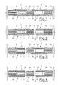
- the in the Fig. 1 to Fig. 4 Shaft 1 shown in one exemplary embodiment has two shaft regions 2, 3 with adjustable rigidity.
- Each shaft portion 2, 3 has a first and a second shaft portion 2a, 2b; 3a, 3b, each with a positive connection region 4, wherein the positive connection region 4 is formed by an external toothing.
- a torsion bar 5, 6 is arranged in each case.
- the shaft 1 in this case has a larger diameter in the area of the first and second shaft sections 2a, 2b, 3a, 3b than in the region of the torsion bars 5, 6.
- Each shaft section 2, 3 with adjustable rigidity is one in the direction of the axis 1a of the shaft 1 longitudinally displaceable, substantially tubular shift sleeve 7, 8 is provided, wherein the shift sleeve 7, 8 on its inner side in each case with the form-fitting regions 4 of the first and second shaft sections 2a, 2b; 3a, 3b has cooperating inner form-fitting region 9, 10, which can be formed for example by an internal toothing.
- Fig. 1 shows the shaft 1, wherein both shift sleeves 7, 8 are in a first position, in which in each case the first shaft sections 2a, 2b; 3a, 3b of each shaft region A, B with adjustable stiffness are mechanically rotationally connected.
- the torsion bars 5, 6 have thus been bridged by the shift sleeves 7, 8.
- the overall stiffness of each shaft region A, B is thus composed of the spring stiffness of the torsion bars 5, 6 and the shift sleeves 7, 8.
- Fig. 2 shows the shaft 1, wherein the left shift sleeve 7 is activated and the right shift sleeve 8 is deactivated.
- the spring stiffness is thus essentially determined by the spring rod 6 in this switching position.
- Fig. 3 shows the shaft 1 in a further switching position, wherein the left shift sleeve 7 is deactivated and the right shift sleeve is activated.
- the spring stiffness of the shaft 1 is determined in this case substantially by the torsion bar 5.
- Fig. 4 shows a further switching position, in which both shift sleeves 7, 8 are deactivated.
- the torsional rigidity of the shaft 1 is thus defined by both spring rods 5, 6.
Landscapes
- Engineering & Computer Science (AREA)
- General Engineering & Computer Science (AREA)
- Mechanical Engineering (AREA)
- Ocean & Marine Engineering (AREA)
- Springs (AREA)
- Gear-Shifting Mechanisms (AREA)
Abstract
Description
- Die Erfindung betrifft eine Welle mit verstellbarer Steifigkeit gemäß dem Oberbegriff von Patentanspruch 1.
- Bei einer solchen Welle ist zwischen einem ersten Wellenabschnitt und einem zweiten Wellenabschnitt zumindest ein Torsionsstab angeordnet, wobei die Welle im Bereich des Torsionsstabes einen kleineren Durchmesser aufweist, als im Bereich der beiden ersten und zweiten Wellenabschnitte.
- Aus der
CH 397 344 A - Die
DE 10 002 259 A1 beschreibt eine Drehmomentübertragungseinrichtung für einen Antriebsstrang eines Kraftfahrzeuges mit einem axial elastischen Bauteil. In einem vorgegebenen radialen Bereich des scheibenförmigen oder ringscheibenförmigen elastischen Bauteils ist eine einer einzustellenden axialen Steifigkeit entsprechende Anzahl über den Umfang verteilte axiale Durchtrennungen eingebracht. Derartige Durchtrennungen begrenzen durch die vermindernde effektive Fläche des scheibenförmigen Bauteils in radialer Richtung die Biegesteifigkeit in axialer Richtung, so dass die Anzahl dieser Durchtrennungen eine Variation der axial wirksamen Steifigkeit von einem nahezu unveränderten Verhalten bei sehr wenigen Durchtrennungen bis zu einer sehr geringen axialen Steifigkeit bei nahezu vollständig durchtrenntem Umfang mit nur wenigen verbleibenden, die Biegesteifigkeiten in radiale Richtung übernehmenden Stegen erreicht werden kann. Das Einbringen der Durchtrennungen erfolgt durch Stanzen, Schneiden oder mit Hilfe Laser-, Wasserstrahl-, Ultraschall- und vergleichbaren Trennmethoden. Nachteilig ist, dass durch die Durchtrennungen eine im Wesentlichen unumkehrbare fixe Einstellung der Drehsteifigkeit erfolgt. - Aufgabe der Erfindung ist es, diese Nachteile zu vermeiden und eine Wellenverbindung zu schaffen, deren Steifigkeit zur Anpassung des Drehschwingungsverhaltens wiederholt verändert werden kann.
- Erfindungsgemäß werden diese Aufgaben durch die Merkmale von Patenanspruch 1 gelöst.
- Insbesondere ist vorgesehen, dass die Welle zumindest eine axial auf der Welle verschiebbare, vorzugsweise rohrförmige Schaltmuffe aufweist, wobei der erste und der zweite Wellenabschnitt der Welle durch die Schaltmuffe in einer ersten Stellung miteinander verbindbar und in einer zweiten Stellung trennbar sind.
- Vorzugsweise ist dabei vorgesehen, dass jeder Wellenabschnitt einen vorzugsweise durch eine Außenverzahnung gebildeten Formschlussbereich aufweist, welcher jeweils mit einem korrespondierenden, vorzugsweise durch eine Innenverzahnung gebildeten Formschlussbereich der Schaltmuffe zusammenwirkt. Durch die Schaltmuffe können die Wellenabschnitte beidseits des Torsionsstabes unter Umgehung des Torsionsstabes miteinander mechanisch drehverbunden werden, wodurch die Drehmomentübertragung zwischen dem ersten und dem zweiten Wellenabschnitt im Wesentlichen über die Schaltmuffe erfolgt. Somit ist in der ersten Stellung der Schaltmuffe der Torsionsstab aktiviert und in der zweiten Stellung der Schaltmuffe deaktiviert.
- Mehrere diskret auswählbare Federsteifigkeiten können erreicht werden, wenn die Welle zumindest zwei in axialer Richtung hintereinander angeordnete Wellenbereiche mit verstellbarer Steifigkeit aufweist, wobei jeder Wellenbereich mit verstellbarer Steifigkeit jeweils zumindest einen Torsionsstab zwischen einem ersten Wellenabschnitt und einem zweiten Wellenabschnitt aufweist, wobei vorzugsweise pro Wellenbereich mit verstellbarer Steifigkeit eine Schaltmuffe vorgesehen ist. Mit den Schaltmuffen können somit mehr als zwei Federsteifigkeiten realisiert werden.
- Dabei ist es besonders vorteilhaft, wenn die Torsionsstäbe unterschiedlicher Wellenbereiche verschiedene Federsteifigkeiten aufweisen.
- Mit zwei hintereinander angeordnete Wellenbereiche mit verstellbarer Steifigkeit, wobei die Wellenbereiche Torsionsstäbe mit unterschiedlichen Federverhalten aufweisen, lassen sich somit mittels zwei Schaltmuffen vier verschiedene Drehsteifigkeiten der Welle realisieren.
- Die Erfindung wird im folgenden anhand der Figuren näher erläutert. Es zeigen:
- Fig. 1
- eine erfindungsgemäße Welle in einem Längsschnitt in einer ersten Schaltstellung;
- Fig. 2
- die Welle in einer zweiten Schaltstellung;
- Fig. 3
- die Welle in einer dritten Schaltstellung; und
- Fig. 4
- die Welle in einer vierten Schaltstellung.
- Die in den
Fig. 1 bis Fig. 4 in einem Ausführungsbeispiel dargestellte Welle 1, beispielsweise eine Antriebswelle für ein Fahrzeug, weist zwei Wellenbereich 2, 3 mit verstellbarer Steifigkeit auf. Jeder Wellenbereich 2, 3 weist einen ersten und einen zweiten Wellenabschnitt 2a, 2b; 3a, 3b mit jeweils einem Formschlussbereich 4 auf, wobei der Formschlussbereich 4 durch eine Außenverzahnung gebildet ist. Zwischen den beiden Wellenabschnitten 2a, 2b; 3a, 3b jedes Wellenbereiches 2, 3 ist jeweils ein Torsionsstab 5, 6 angeordnet. Die Welle 1 weist dabei im Bereich der ersten und zweiten Wellenabschnitte 2a, 2b, 3a, 3b einen größeren Durchmesser auf, als im Bereich der Torsionsstäbe 5, 6. Pro Wellenbereich 2, 3 mit verstellbarer Steifigkeit ist eine in Richtung der Achse 1a der Welle 1 längsverschiebbare, im Wesentlichen rohrförmige Schaltmuffe 7, 8 vorgesehen, wobei die Schaltmuffe 7, 8 an Ihrer Innenseite jeweils mit den Formschlussbereichen 4 der ersten und zweiten Wellenabschnitte 2a, 2b; 3a, 3b zusammenwirkenden inneren Formschlussbereich 9, 10 aufweist, welcher beispielsweise durch eine Innenverzahnung gebildet werden kann. - Durch Verschieben der Schaltmuffen 7, 8 können die ersten und zweiten Wellenabschnitte 2a, 2b; 3a, 3b jedes Wellenbereiches A, B veränderbarer Steifigkeit miteinander mechanisch drehverbunden oder frei gestaltet werden.
-
Fig. 1 zeigt die Welle 1, wobei sich beide Schaltmuffen 7, 8 in einer ersten Stellung befinden, in welcher jeweils die ersten Wellenabschnitte 2a, 2b; 3a, 3b jedes Wellenbereiches A, B mit verstellbarer Steifigkeit mechanisch drehverbunden sind. Die Torsionsstäbe 5, 6 sind somit durch die Schaltmuffen 7, 8 überbrückt worden. Die Gesamtsteifigkeit jedes Wellenbereiches A, B setzt sich somit aus den Federsteifigkeiten der Torsionsstäbe 5, 6 und der Schaltmuffen 7, 8 zusammen. -
Fig. 2 zeigt die Welle 1, wobei die linke Schaltmuffe 7 aktiviert und die rechte Schaltmuffe 8 deaktiviert ist. Die Federsteifigkeit wird in dieser Schaltstellung somit im Wesentlichen durch den Federstab 6 bestimmt. -
Fig. 3 zeigt die Welle 1 in einer weiteren Schaltstellung, wobei die linke Schaltmuffe 7 deaktiviert und die rechte Schaltmuffe aktiviert wird. Die Federsteifigkeit der Welle 1 wird in diesem Fall im Wesentlichen durch den Torsionsstab 5 bestimmt. -
Fig. 4 zeigt eine weitere Schaltstellung, bei der beide Schaltmuffen 7, 8 deaktiviert sind. Die Torsionssteifigkeit der Welle 1 wird somit durch beide Federstäbe 5, 6 definiert. - Mit der beschriebenen Welle und den Schaltmuffen 7, 8 können somit sehr einfach verschiedene und beliebig oft schaltbare Federsteifigkeiten und somit das Antriebsstrangverhalten beeinflusst werden.
Claims (5)
- Welle (1) mit verstellbarer Steifigkeit, wobei zwischen einem ersten Wellenabschnitt (2a; 3a) und einem zweiten Wellenabschnitt (2b; 3b) zumindest ein Torsionsstab (5, 6) angeordnet ist, wobei die Welle (1) im Bereich des Torsionsstabes (5, 6) einen kleineren Durchmesser aufweist, als im Bereich der beiden ersten und zweiten Wellenabschnitte (2a, 2b; 3a, 3b), dadurch gekennzeichnet, dass die Welle (1) zumindest eine axial verschiebbare, vorzugsweise rohrförmige Schaltmuffe (7, 8) aufweist, wobei der erste und der zweite Wellenabschnitt (2a, 2b; 3a, 3b) der Welle (1) durch die Schaltmuffe (7, 8) in einer ersten Stellung miteinander verbindbar und in einer zweiten Stellung trennbar sind.
- Welle (1) nach Anspruch 1, dadurch gekennzeichnet, dass jeder Wellenabschnitt (2a, 2b; 3a, 3b) einen vorzugsweise durch eine Außenverzahnung gebildeten Formschlussbereich (4) aufweist, welcher jeweils mit einem korrespondierenden, vorzugsweise durch eine Innenverzahnung gebildeten Formschlussbereich (9, 10) der Schaltmuffe (7, 8) zusammenwirkt.
- Welle (1) nach Anspruch 1 oder 2, dadurch gekennzeichnet, dass die Welle (1) zumindest zwei in axialer Richtung hintereinander angeordnete Wellenbereiche (2, 3) mit verstellbarer Steifigkeit aufweist, wobei jeder Wellenbereich (2, 3) mit verstellbarer Steifigkeit jeweils zumindest einen Torsionsstab (5, 6) zwischen einem ersten Wellenabschnitt (2a; 3a) und einem zweiten Wellenabschnitt (2b; 3b) aufweist.
- Welle (1) nach Anspruch 3, dadurch gekennzeichnet, dass pro Wellenbereich (2, 3) mit verstellbarer Steifigkeit eine Schaltmuffe (7, 8) vorgesehen ist.
- Welle (1) nach Anspruch 3 bis 4, dadurch gekennzeichnet, dass die Torsionsstäbe (5, 6) unterschiedlicher Wellenbereiche (2, 3) verschiedene Federsteifigkeiten aufweisen.
Applications Claiming Priority (1)
| Application Number | Priority Date | Filing Date | Title |
|---|---|---|---|
| AT11202009A AT506732B1 (de) | 2009-07-16 | 2009-07-16 | Welle mit verstellbarer steifigkeit |
Publications (2)
| Publication Number | Publication Date |
|---|---|
| EP2278183A1 true EP2278183A1 (de) | 2011-01-26 |
| EP2278183B1 EP2278183B1 (de) | 2013-04-17 |
Family
ID=41259956
Family Applications (1)
| Application Number | Title | Priority Date | Filing Date |
|---|---|---|---|
| EP20100169665 Not-in-force EP2278183B1 (de) | 2009-07-16 | 2010-07-15 | Welle mit verstellbarer steifigkeit |
Country Status (2)
| Country | Link |
|---|---|
| EP (1) | EP2278183B1 (de) |
| AT (1) | AT506732B1 (de) |
Cited By (3)
| Publication number | Priority date | Publication date | Assignee | Title |
|---|---|---|---|---|
| DE102011120095A1 (de) | 2011-12-02 | 2013-06-06 | Fraunhofer-Gesellschaft zur Förderung der angewandten Forschung e.V. | Wellenanordnung sowie Verfahren zum Weiterleiten von um eine Drehachse wirkenden Drehmomenten |
| CN103807281A (zh) * | 2014-03-13 | 2014-05-21 | 上海纳铁福传动系统有限公司 | 一种高扭转刚度传动轴的轻量化设计方法 |
| DE102012111610A1 (de) | 2012-11-29 | 2014-06-18 | Fev Gmbh | Vorrichtung zum aktiven Beeinflussen einer Steifigkeit eines Antriebstranges sowie Antriebsstrang |
Families Citing this family (1)
| Publication number | Priority date | Publication date | Assignee | Title |
|---|---|---|---|---|
| US9822835B1 (en) | 2014-02-20 | 2017-11-21 | Hrl Laboratories, Llc | Torsion springs with changeable stiffness |
Citations (5)
| Publication number | Priority date | Publication date | Assignee | Title |
|---|---|---|---|---|
| CH397344A (de) | 1961-03-07 | 1965-08-15 | Rheinmetall Gmbh | Drehelastische Welle, insbesondere Gelenkwelle |
| JPS6357309A (ja) * | 1986-08-26 | 1988-03-12 | Toyota Motor Corp | 剛性可変スタビライザ |
| DE10002259A1 (de) | 1999-01-25 | 2000-07-27 | Luk Lamellen & Kupplungsbau | Drehmomentübertragungseinrichtung |
| US6428019B1 (en) * | 2000-09-18 | 2002-08-06 | American Axle & Manufacturing, Inc. | Semi-active anti-roll system |
| US20060194635A1 (en) * | 2004-11-16 | 2006-08-31 | John Cunningham | Variable stiffness flexible joint |
-
2009
- 2009-07-16 AT AT11202009A patent/AT506732B1/de not_active IP Right Cessation
-
2010
- 2010-07-15 EP EP20100169665 patent/EP2278183B1/de not_active Not-in-force
Patent Citations (5)
| Publication number | Priority date | Publication date | Assignee | Title |
|---|---|---|---|---|
| CH397344A (de) | 1961-03-07 | 1965-08-15 | Rheinmetall Gmbh | Drehelastische Welle, insbesondere Gelenkwelle |
| JPS6357309A (ja) * | 1986-08-26 | 1988-03-12 | Toyota Motor Corp | 剛性可変スタビライザ |
| DE10002259A1 (de) | 1999-01-25 | 2000-07-27 | Luk Lamellen & Kupplungsbau | Drehmomentübertragungseinrichtung |
| US6428019B1 (en) * | 2000-09-18 | 2002-08-06 | American Axle & Manufacturing, Inc. | Semi-active anti-roll system |
| US20060194635A1 (en) * | 2004-11-16 | 2006-08-31 | John Cunningham | Variable stiffness flexible joint |
Cited By (6)
| Publication number | Priority date | Publication date | Assignee | Title |
|---|---|---|---|---|
| DE102011120095A1 (de) | 2011-12-02 | 2013-06-06 | Fraunhofer-Gesellschaft zur Förderung der angewandten Forschung e.V. | Wellenanordnung sowie Verfahren zum Weiterleiten von um eine Drehachse wirkenden Drehmomenten |
| WO2013079203A1 (de) | 2011-12-02 | 2013-06-06 | Fraunhofer-Gesellschaft zur Förderung der angewandten Forschung e.V. | Wellenanordnung sowie verfahren zum weiterleiten von um eine drehachse wirkenden drehmomenten |
| US9404542B2 (en) | 2011-12-02 | 2016-08-02 | Fraunhofer-Gesellschaft Zur Forderung Der | Shaft arrangement and method for relaying torques acting around a rotational axis |
| DE102012111610A1 (de) | 2012-11-29 | 2014-06-18 | Fev Gmbh | Vorrichtung zum aktiven Beeinflussen einer Steifigkeit eines Antriebstranges sowie Antriebsstrang |
| CN103807281A (zh) * | 2014-03-13 | 2014-05-21 | 上海纳铁福传动系统有限公司 | 一种高扭转刚度传动轴的轻量化设计方法 |
| CN103807281B (zh) * | 2014-03-13 | 2016-01-20 | 上海纳铁福传动系统有限公司 | 一种高扭转刚度传动轴的轻量化设计方法 |
Also Published As
| Publication number | Publication date |
|---|---|
| AT506732A2 (de) | 2009-11-15 |
| AT506732B1 (de) | 2011-01-15 |
| AT506732A3 (de) | 2010-09-15 |
| EP2278183B1 (de) | 2013-04-17 |
Similar Documents
| Publication | Publication Date | Title |
|---|---|---|
| DE102015224775A1 (de) | Spindelantrieb und Aktuator mit Spindelantrieb | |
| EP2278183B1 (de) | Welle mit verstellbarer steifigkeit | |
| WO2017089058A1 (de) | Lenkeinrichtung für ein kraftfahrzeug | |
| EP2033859B1 (de) | Verriegelungseinrichtung für eine Welle eines Lenksystems | |
| DE19654069A1 (de) | Verfahren und Vorrichtung zur Vermeidung des Spiels zwischen zwei kämmenden Zahnrädern eines Getriebezuges | |
| EP3882478B1 (de) | Antriebsstrang mit einer beweglichen kupplung zwischen einer motorwelle und einer eingangswelle eines schaltgetriebes | |
| WO2016071017A1 (de) | Nockenwelle mit wenigstens einem axial fixierten schiebeelement | |
| AT515433B1 (de) | Welle mit verstellbarer Steifigkeit | |
| DE102007012772B4 (de) | Elastisches Lagerelement | |
| DE102016103197A1 (de) | Riemengetriebe und lenksystem | |
| AT507923B1 (de) | Wellenverbindung | |
| DE102014212433A1 (de) | Stabilisator | |
| DE102022108834B4 (de) | Aktuierungselement für eine Kupplung, mit zumindest einem Federelement und Kupplung | |
| WO2017211513A1 (de) | Aktuator für eine hinterachslenkung | |
| DE102020208514A1 (de) | Aktuator einer steer-by-wire-Lenkvorrichtung eines Kraftfahrzeuges sowie Verfahren zur Montage eines Aktuators einer steer-by-wire-Lenkvorrichtung | |
| DE102017110183A1 (de) | Drehstab eines Wankstabilisators | |
| DE102019123055A1 (de) | Zahnradverbund, insbesondere zur Bildung eines Mehrfach-Planetenrades | |
| DE102020128521B4 (de) | Spindelgetriebe, längseinsteller, fahrzeugsitz | |
| DE102023207299A1 (de) | Lenkstange für ein Kraftfahrzeug-Lenkgetriebe sowie Kraftfahrzeug-Lenkgetriebe einer Steer-by-wire-Kraftfahrzeuglenkung | |
| DE102024119130A1 (de) | Planetenwälzgewindetrieb für einen Lenkaktuator, Lenkaktuator mit einem solchen Planetenwälzgewindetrieb und Hinterachslenkung | |
| DE102015105351B4 (de) | Getriebe für eine Servolenkung und Servolenkung | |
| WO2005084971A1 (de) | Geteilter stabilisator für ein kraftfahrzeug und verfahren zur herstellung des stabilisators | |
| DE102023131896A1 (de) | Kugelgewindetrieb sowie Lenksystem mit einem solchen Kugelgewindetrieb | |
| WO2024126276A1 (de) | Schiebenocken und schiebenockenwelle | |
| DE102011117642A1 (de) | Aktiver Stabilisator zur Wankstabilisierung bei Kraftfahrzeugen |
Legal Events
| Date | Code | Title | Description |
|---|---|---|---|
| PUAI | Public reference made under article 153(3) epc to a published international application that has entered the european phase |
Free format text: ORIGINAL CODE: 0009012 |
|
| AK | Designated contracting states |
Kind code of ref document: A1 Designated state(s): AL AT BE BG CH CY CZ DE DK EE ES FI FR GB GR HR HU IE IS IT LI LT LU LV MC MK MT NL NO PL PT RO SE SI SK SM TR |
|
| AX | Request for extension of the european patent |
Extension state: BA ME RS |
|
| 17P | Request for examination filed |
Effective date: 20110719 |
|
| RIC1 | Information provided on ipc code assigned before grant |
Ipc: F16C 3/02 20060101ALI20120918BHEP Ipc: F16F 1/14 20060101AFI20120918BHEP |
|
| GRAP | Despatch of communication of intention to grant a patent |
Free format text: ORIGINAL CODE: EPIDOSNIGR1 |
|
| GRAS | Grant fee paid |
Free format text: ORIGINAL CODE: EPIDOSNIGR3 |
|
| GRAA | (expected) grant |
Free format text: ORIGINAL CODE: 0009210 |
|
| AK | Designated contracting states |
Kind code of ref document: B1 Designated state(s): AL AT BE BG CH CY CZ DE DK EE ES FI FR GB GR HR HU IE IS IT LI LT LU LV MC MK MT NL NO PL PT RO SE SI SK SM TR |
|
| REG | Reference to a national code |
Ref country code: GB Ref legal event code: FG4D Free format text: NOT ENGLISH |
|
| REG | Reference to a national code |
Ref country code: CH Ref legal event code: EP |
|
| REG | Reference to a national code |
Ref country code: IE Ref legal event code: FG4D Free format text: LANGUAGE OF EP DOCUMENT: GERMAN |
|
| REG | Reference to a national code |
Ref country code: AT Ref legal event code: REF Ref document number: 607500 Country of ref document: AT Kind code of ref document: T Effective date: 20130515 |
|
| REG | Reference to a national code |
Ref country code: DE Ref legal event code: R096 Ref document number: 502010002941 Country of ref document: DE Effective date: 20130613 |
|
| REG | Reference to a national code |
Ref country code: CH Ref legal event code: NV Representative=s name: ISLER AND PEDRAZZINI AG, CH |
|
| REG | Reference to a national code |
Ref country code: LT Ref legal event code: MG4D |
|
| REG | Reference to a national code |
Ref country code: NL Ref legal event code: VDEP Effective date: 20130417 |
|
| PG25 | Lapsed in a contracting state [announced via postgrant information from national office to epo] |
Ref country code: NO Free format text: LAPSE BECAUSE OF FAILURE TO SUBMIT A TRANSLATION OF THE DESCRIPTION OR TO PAY THE FEE WITHIN THE PRESCRIBED TIME-LIMIT Effective date: 20130717 Ref country code: SI Free format text: LAPSE BECAUSE OF FAILURE TO SUBMIT A TRANSLATION OF THE DESCRIPTION OR TO PAY THE FEE WITHIN THE PRESCRIBED TIME-LIMIT Effective date: 20130417 Ref country code: GR Free format text: LAPSE BECAUSE OF FAILURE TO SUBMIT A TRANSLATION OF THE DESCRIPTION OR TO PAY THE FEE WITHIN THE PRESCRIBED TIME-LIMIT Effective date: 20130718 Ref country code: IS Free format text: LAPSE BECAUSE OF FAILURE TO SUBMIT A TRANSLATION OF THE DESCRIPTION OR TO PAY THE FEE WITHIN THE PRESCRIBED TIME-LIMIT Effective date: 20130817 Ref country code: FI Free format text: LAPSE BECAUSE OF FAILURE TO SUBMIT A TRANSLATION OF THE DESCRIPTION OR TO PAY THE FEE WITHIN THE PRESCRIBED TIME-LIMIT Effective date: 20130417 Ref country code: ES Free format text: LAPSE BECAUSE OF FAILURE TO SUBMIT A TRANSLATION OF THE DESCRIPTION OR TO PAY THE FEE WITHIN THE PRESCRIBED TIME-LIMIT Effective date: 20130728 Ref country code: SE Free format text: LAPSE BECAUSE OF FAILURE TO SUBMIT A TRANSLATION OF THE DESCRIPTION OR TO PAY THE FEE WITHIN THE PRESCRIBED TIME-LIMIT Effective date: 20130417 Ref country code: LT Free format text: LAPSE BECAUSE OF FAILURE TO SUBMIT A TRANSLATION OF THE DESCRIPTION OR TO PAY THE FEE WITHIN THE PRESCRIBED TIME-LIMIT Effective date: 20130417 Ref country code: PT Free format text: LAPSE BECAUSE OF FAILURE TO SUBMIT A TRANSLATION OF THE DESCRIPTION OR TO PAY THE FEE WITHIN THE PRESCRIBED TIME-LIMIT Effective date: 20130819 |
|
| PG25 | Lapsed in a contracting state [announced via postgrant information from national office to epo] |
Ref country code: BG Free format text: LAPSE BECAUSE OF FAILURE TO SUBMIT A TRANSLATION OF THE DESCRIPTION OR TO PAY THE FEE WITHIN THE PRESCRIBED TIME-LIMIT Effective date: 20130717 Ref country code: HR Free format text: LAPSE BECAUSE OF FAILURE TO SUBMIT A TRANSLATION OF THE DESCRIPTION OR TO PAY THE FEE WITHIN THE PRESCRIBED TIME-LIMIT Effective date: 20130417 Ref country code: LV Free format text: LAPSE BECAUSE OF FAILURE TO SUBMIT A TRANSLATION OF THE DESCRIPTION OR TO PAY THE FEE WITHIN THE PRESCRIBED TIME-LIMIT Effective date: 20130417 Ref country code: PL Free format text: LAPSE BECAUSE OF FAILURE TO SUBMIT A TRANSLATION OF THE DESCRIPTION OR TO PAY THE FEE WITHIN THE PRESCRIBED TIME-LIMIT Effective date: 20130417 Ref country code: CY Free format text: LAPSE BECAUSE OF FAILURE TO SUBMIT A TRANSLATION OF THE DESCRIPTION OR TO PAY THE FEE WITHIN THE PRESCRIBED TIME-LIMIT Effective date: 20130417 |
|
| BERE | Be: lapsed |
Owner name: AVL LIST GMBH Effective date: 20130731 |
|
| PG25 | Lapsed in a contracting state [announced via postgrant information from national office to epo] |
Ref country code: EE Free format text: LAPSE BECAUSE OF FAILURE TO SUBMIT A TRANSLATION OF THE DESCRIPTION OR TO PAY THE FEE WITHIN THE PRESCRIBED TIME-LIMIT Effective date: 20130417 Ref country code: DK Free format text: LAPSE BECAUSE OF FAILURE TO SUBMIT A TRANSLATION OF THE DESCRIPTION OR TO PAY THE FEE WITHIN THE PRESCRIBED TIME-LIMIT Effective date: 20130417 Ref country code: SK Free format text: LAPSE BECAUSE OF FAILURE TO SUBMIT A TRANSLATION OF THE DESCRIPTION OR TO PAY THE FEE WITHIN THE PRESCRIBED TIME-LIMIT Effective date: 20130417 Ref country code: CZ Free format text: LAPSE BECAUSE OF FAILURE TO SUBMIT A TRANSLATION OF THE DESCRIPTION OR TO PAY THE FEE WITHIN THE PRESCRIBED TIME-LIMIT Effective date: 20130417 |
|
| PLBE | No opposition filed within time limit |
Free format text: ORIGINAL CODE: 0009261 |
|
| STAA | Information on the status of an ep patent application or granted ep patent |
Free format text: STATUS: NO OPPOSITION FILED WITHIN TIME LIMIT |
|
| PG25 | Lapsed in a contracting state [announced via postgrant information from national office to epo] |
Ref country code: NL Free format text: LAPSE BECAUSE OF FAILURE TO SUBMIT A TRANSLATION OF THE DESCRIPTION OR TO PAY THE FEE WITHIN THE PRESCRIBED TIME-LIMIT Effective date: 20130417 Ref country code: MC Free format text: LAPSE BECAUSE OF FAILURE TO SUBMIT A TRANSLATION OF THE DESCRIPTION OR TO PAY THE FEE WITHIN THE PRESCRIBED TIME-LIMIT Effective date: 20130417 Ref country code: RO Free format text: LAPSE BECAUSE OF FAILURE TO SUBMIT A TRANSLATION OF THE DESCRIPTION OR TO PAY THE FEE WITHIN THE PRESCRIBED TIME-LIMIT Effective date: 20130417 |
|
| 26N | No opposition filed |
Effective date: 20140120 |
|
| REG | Reference to a national code |
Ref country code: IE Ref legal event code: MM4A |
|
| PG25 | Lapsed in a contracting state [announced via postgrant information from national office to epo] |
Ref country code: BE Free format text: LAPSE BECAUSE OF NON-PAYMENT OF DUE FEES Effective date: 20130731 |
|
| REG | Reference to a national code |
Ref country code: DE Ref legal event code: R097 Ref document number: 502010002941 Country of ref document: DE Effective date: 20140120 |
|
| PG25 | Lapsed in a contracting state [announced via postgrant information from national office to epo] |
Ref country code: IE Free format text: LAPSE BECAUSE OF NON-PAYMENT OF DUE FEES Effective date: 20130715 |
|
| PG25 | Lapsed in a contracting state [announced via postgrant information from national office to epo] |
Ref country code: SM Free format text: LAPSE BECAUSE OF FAILURE TO SUBMIT A TRANSLATION OF THE DESCRIPTION OR TO PAY THE FEE WITHIN THE PRESCRIBED TIME-LIMIT Effective date: 20130417 |
|
| PG25 | Lapsed in a contracting state [announced via postgrant information from national office to epo] |
Ref country code: TR Free format text: LAPSE BECAUSE OF FAILURE TO SUBMIT A TRANSLATION OF THE DESCRIPTION OR TO PAY THE FEE WITHIN THE PRESCRIBED TIME-LIMIT Effective date: 20130417 Ref country code: MT Free format text: LAPSE BECAUSE OF FAILURE TO SUBMIT A TRANSLATION OF THE DESCRIPTION OR TO PAY THE FEE WITHIN THE PRESCRIBED TIME-LIMIT Effective date: 20130417 |
|
| PG25 | Lapsed in a contracting state [announced via postgrant information from national office to epo] |
Ref country code: LU Free format text: LAPSE BECAUSE OF NON-PAYMENT OF DUE FEES Effective date: 20130715 Ref country code: HU Free format text: LAPSE BECAUSE OF FAILURE TO SUBMIT A TRANSLATION OF THE DESCRIPTION OR TO PAY THE FEE WITHIN THE PRESCRIBED TIME-LIMIT; INVALID AB INITIO Effective date: 20100715 Ref country code: MK Free format text: LAPSE BECAUSE OF FAILURE TO SUBMIT A TRANSLATION OF THE DESCRIPTION OR TO PAY THE FEE WITHIN THE PRESCRIBED TIME-LIMIT Effective date: 20130417 |
|
| REG | Reference to a national code |
Ref country code: FR Ref legal event code: PLFP Year of fee payment: 7 |
|
| REG | Reference to a national code |
Ref country code: AT Ref legal event code: MM01 Ref document number: 607500 Country of ref document: AT Kind code of ref document: T Effective date: 20150715 |
|
| PG25 | Lapsed in a contracting state [announced via postgrant information from national office to epo] |
Ref country code: AT Free format text: LAPSE BECAUSE OF NON-PAYMENT OF DUE FEES Effective date: 20150715 |
|
| REG | Reference to a national code |
Ref country code: FR Ref legal event code: PLFP Year of fee payment: 8 |
|
| REG | Reference to a national code |
Ref country code: FR Ref legal event code: PLFP Year of fee payment: 9 |
|
| PG25 | Lapsed in a contracting state [announced via postgrant information from national office to epo] |
Ref country code: AL Free format text: LAPSE BECAUSE OF FAILURE TO SUBMIT A TRANSLATION OF THE DESCRIPTION OR TO PAY THE FEE WITHIN THE PRESCRIBED TIME-LIMIT Effective date: 20130417 |
|
| PGFP | Annual fee paid to national office [announced via postgrant information from national office to epo] |
Ref country code: IT Payment date: 20180731 Year of fee payment: 9 Ref country code: FR Payment date: 20180731 Year of fee payment: 9 |
|
| PGFP | Annual fee paid to national office [announced via postgrant information from national office to epo] |
Ref country code: GB Payment date: 20180731 Year of fee payment: 9 Ref country code: CH Payment date: 20180730 Year of fee payment: 9 |
|
| REG | Reference to a national code |
Ref country code: CH Ref legal event code: PL |
|
| GBPC | Gb: european patent ceased through non-payment of renewal fee |
Effective date: 20190715 |
|
| PG25 | Lapsed in a contracting state [announced via postgrant information from national office to epo] |
Ref country code: GB Free format text: LAPSE BECAUSE OF NON-PAYMENT OF DUE FEES Effective date: 20190715 |
|
| PG25 | Lapsed in a contracting state [announced via postgrant information from national office to epo] |
Ref country code: CH Free format text: LAPSE BECAUSE OF NON-PAYMENT OF DUE FEES Effective date: 20190731 Ref country code: LI Free format text: LAPSE BECAUSE OF NON-PAYMENT OF DUE FEES Effective date: 20190731 |
|
| PG25 | Lapsed in a contracting state [announced via postgrant information from national office to epo] |
Ref country code: FR Free format text: LAPSE BECAUSE OF NON-PAYMENT OF DUE FEES Effective date: 20190731 |
|
| PG25 | Lapsed in a contracting state [announced via postgrant information from national office to epo] |
Ref country code: IT Free format text: LAPSE BECAUSE OF NON-PAYMENT OF DUE FEES Effective date: 20190715 |
|
| P01 | Opt-out of the competence of the unified patent court (upc) registered |
Effective date: 20230502 |
|
| PGFP | Annual fee paid to national office [announced via postgrant information from national office to epo] |
Ref country code: DE Payment date: 20240731 Year of fee payment: 15 |
|
| REG | Reference to a national code |
Ref country code: DE Ref legal event code: R119 Ref document number: 502010002941 Country of ref document: DE |
|
| PG25 | Lapsed in a contracting state [announced via postgrant information from national office to epo] |
Ref country code: DE Free format text: LAPSE BECAUSE OF NON-PAYMENT OF DUE FEES Effective date: 20260203 |