EP2277813A1 - Device for switching between conveyance paths for paper sheets or the like - Google Patents
Device for switching between conveyance paths for paper sheets or the like Download PDFInfo
- Publication number
- EP2277813A1 EP2277813A1 EP09729360A EP09729360A EP2277813A1 EP 2277813 A1 EP2277813 A1 EP 2277813A1 EP 09729360 A EP09729360 A EP 09729360A EP 09729360 A EP09729360 A EP 09729360A EP 2277813 A1 EP2277813 A1 EP 2277813A1
- Authority
- EP
- European Patent Office
- Prior art keywords
- blade
- conveyance path
- conveyance
- switching
- paper sheets
- Prior art date
- Legal status (The legal status is an assumption and is not a legal conclusion. Google has not performed a legal analysis and makes no representation as to the accuracy of the status listed.)
- Withdrawn
Links
- 238000010586 diagram Methods 0.000 description 20
- 230000006870 function Effects 0.000 description 2
- 241000119744 Allium motor Species 0.000 description 1
- 230000001133 acceleration Effects 0.000 description 1
- 230000000694 effects Effects 0.000 description 1
- 238000005516 engineering process Methods 0.000 description 1
- 238000000465 moulding Methods 0.000 description 1
- 239000011347 resin Substances 0.000 description 1
- 229920005989 resin Polymers 0.000 description 1
Images


Classifications
-
- B—PERFORMING OPERATIONS; TRANSPORTING
- B65—CONVEYING; PACKING; STORING; HANDLING THIN OR FILAMENTARY MATERIAL
- B65H—HANDLING THIN OR FILAMENTARY MATERIAL, e.g. SHEETS, WEBS, CABLES
- B65H29/00—Delivering or advancing articles from machines; Advancing articles to or into piles
- B65H29/58—Article switches or diverters
-
- B—PERFORMING OPERATIONS; TRANSPORTING
- B65—CONVEYING; PACKING; STORING; HANDLING THIN OR FILAMENTARY MATERIAL
- B65H—HANDLING THIN OR FILAMENTARY MATERIAL, e.g. SHEETS, WEBS, CABLES
- B65H2301/00—Handling processes for sheets or webs
- B65H2301/30—Orientation, displacement, position of the handled material
- B65H2301/31—Features of transport path
- B65H2301/312—Features of transport path for transport path involving at least two planes of transport forming an angle between each other
- B65H2301/3124—Y-shaped
-
- B—PERFORMING OPERATIONS; TRANSPORTING
- B65—CONVEYING; PACKING; STORING; HANDLING THIN OR FILAMENTARY MATERIAL
- B65H—HANDLING THIN OR FILAMENTARY MATERIAL, e.g. SHEETS, WEBS, CABLES
- B65H2301/00—Handling processes for sheets or webs
- B65H2301/40—Type of handling process
- B65H2301/44—Moving, forwarding, guiding material
- B65H2301/448—Diverting
- B65H2301/4482—Diverting to multiple paths, i.e. more than 2
- B65H2301/44822—3 paths
-
- B—PERFORMING OPERATIONS; TRANSPORTING
- B65—CONVEYING; PACKING; STORING; HANDLING THIN OR FILAMENTARY MATERIAL
- B65H—HANDLING THIN OR FILAMENTARY MATERIAL, e.g. SHEETS, WEBS, CABLES
- B65H2403/00—Power transmission; Driving means
- B65H2403/90—Machine drive
- B65H2403/94—Other features of machine drive
- B65H2403/942—Bidirectional powered handling device
-
- B—PERFORMING OPERATIONS; TRANSPORTING
- B65—CONVEYING; PACKING; STORING; HANDLING THIN OR FILAMENTARY MATERIAL
- B65H—HANDLING THIN OR FILAMENTARY MATERIAL, e.g. SHEETS, WEBS, CABLES
- B65H2404/00—Parts for transporting or guiding the handled material
- B65H2404/60—Other elements in face contact with handled material
- B65H2404/63—Oscillating, pivoting around an axis parallel to face of material, e.g. diverting means
-
- B—PERFORMING OPERATIONS; TRANSPORTING
- B65—CONVEYING; PACKING; STORING; HANDLING THIN OR FILAMENTARY MATERIAL
- B65H—HANDLING THIN OR FILAMENTARY MATERIAL, e.g. SHEETS, WEBS, CABLES
- B65H2511/00—Dimensions; Position; Numbers; Identification; Occurrences
- B65H2511/20—Location in space
- B65H2511/21—Angle
- B65H2511/212—Rotary position
-
- B—PERFORMING OPERATIONS; TRANSPORTING
- B65—CONVEYING; PACKING; STORING; HANDLING THIN OR FILAMENTARY MATERIAL
- B65H—HANDLING THIN OR FILAMENTARY MATERIAL, e.g. SHEETS, WEBS, CABLES
- B65H2701/00—Handled material; Storage means
- B65H2701/10—Handled articles or webs
- B65H2701/19—Specific article or web
- B65H2701/1912—Banknotes, bills and cheques or the like
Definitions
- the present invention relates to a device for switching between conveyance paths for paper sheets or the like, which is provided in a device or the like for handling paper sheets or the like and is for switching conveyance directions of banknotes.
- a related art device for switching between conveyance paths for paper sheets or the like switches conveyance directions of banknotes between three directions by conveying and guiding the banknotes, which serve as an example of the paper sheets or the like, while driving solenoids of two types: a solenoid that serves as a drive source that drives a gate for switching a conveyance direction from one conveyance path to another conveyance path; and a solenoid that serves as a drive source that drives a stopping member for stopping rotation of the gate (for example, see paragraph [0013] and Fig. 1 of Japanese Patent Application Laid-Open (JP-A) No. 2006-213528 ).
- the device for switching between conveyance paths for paper sheets or the like is larger.
- the present invention provides a means for solving this issue.
- One aspect of the present invention is a device for switching between conveyance paths for paper sheets or the like, including a conveyance path switching blade provided at a branch section at which conveyance paths branch in three directions, the conveyance path switching blade rotating to perform a switching operation for guiding paper sheets or the like sent from any one of the conveyance paths to either of the other two conveyance paths.
- the branch section is constructed so as to extend in three directions
- the conveyance path switching blade includes guide sections that protrude in three directions from a center of the rotation, angles formed between one of the guide sections and the other two of the guide sections are larger than an angle formed between two of the conveyance paths, and the conveyance path switching blade is rotated by a motor.
- the present invention is provided with the conveyance path switching blade provided with the three protruding guide sections, and this conveyance path switching blade is rotated by a stepper motor. Therefore, there may be a single drive source and the device may be made small.
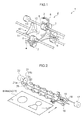
- Fig. 1 is an explanatory diagram illustrating the device for switching between conveyance paths for paper sheets or the like of the exemplary embodiment.
- Fig. 1 shows a device 1 for switching between conveyance paths for paper sheets or the like and describes an example in which banknotes serve as the paper sheets or the like.
- a branch section 2 is formed of three curved banknote guides 3, 4 and 5.
- the banknote guides 3, 4 and 5 are arrayed in a substantially triangular shape with gaps of a size through which banknotes may pass.
- the branch section 2 guides banknotes, which are conveyed along unillustrated banknote conveyance paths and whose conveyance directions are to be switched.
- Cutouts are provided at pairs of locations of each of the banknote guides 3, 4 and 5.
- the positions of the cutouts are, as illustrated in Fig. 1 , a location of the banknote guide 3 that opposes the banknote guide 4 and a location that opposes the banknote guide 5.
- the cutouts provided in the banknote guide 4 are at a location that opposes the banknote guide 3 and a location that opposes the banknote guide 5.
- the cutout at the location that opposes the banknote guide 3 has its position set so as to be disposed to oppose the cutout in the banknote guide 3 that is provided at the location opposing the banknote guide 4.
- the positions of the cutouts provided in the banknote guide 5 are at locations that oppose the banknote guides 3 and 4 and are disposed to oppose the cutouts provided in the banknote guides 3 and 4.
- Feed rollers 6 are mounted so as to protrude into the gaps of the branch section 2 through the cutouts provided in the banknote guide 3 and the cutouts at the locations of the banknote guide 4 that oppose the banknote guide 5.
- press rollers 7 protrude into the gaps of the branch section 2 through the cutouts at the locations of the banknote guide 4 that oppose the banknote guide 3 and the cutouts in the banknote guide 5. Thus, the press rollers 7 are disposed to oppose the feed rollers 6 and nip banknotes against the feed rollers 6. The cutouts have margins assured so as not to interfere with the feed rollers 6.
- Conveyance paths extend in three directions from the branch section 2 of the present exemplary embodiment. These conveyance paths are provided in a radial pattern with intervals of 120°. Accordingly, the pairs of feed rollers 6 and press rollers 7 are arrayed at equal angles of 120° each.
- a conveyance path switching blade 10 is provided in line with the banknote guides 3, 4 and 5 along an axial direction of the feed rollers 6 and press rollers 7.
- the conveyance path switching blade 10 includes guide sections that protrude in three directions from a center of rotation. One of these guide sections is a first blade 11.
- the conveyance path switching blade 10 is constructed such that angles formed between the first blade 11 and the other guide sections (a second blade 12 and a third blade 13) are larger (for example, 150°) than at least the angles formed between pairs of the conveyance paths extending from the branch section 2.
- the conveyance path switching blade 10 functions so as to guide banknotes that are conveyed from one of the conveyance paths while switching the conveyance direction toward either conveyance path of the other two conveyance paths.
- a curved face is formed from the first blade 11 to the second blade 12 or the third blade 13, and this curved face acts as a guide surface for the banknotes. So that the conveyance path switching blade 10 and the banknote guides 3, 4 and 5 do not interfere, cutouts formed as, for example, square holes are provided in the banknote guides 3, 4 and 5, and other structural components and the like are not disposed in a rotation track of the conveyance path switching blade 10.
- Fig. 2 is an explanatory diagram illustrating a state in which the branch section and the conveyance path switching blades are arrayed.
- Fig. 2 is shown in a state in which the branch section 2 is not illustrated.
- toothed pulleys 15 are provided at one end of shafts, partways along which shafts the feed rollers 6 are mounted.
- the feed rollers 6 of the present exemplary embodiment are provided at the cutouts of the banknote guide 3 and the cutouts of the banknote guide 4. Accordingly, there are three shafts and they are independently rotated,
- the toothed pulleys 15 are mounted so as to be fixed to two shafts, as illustrated in Fig. 2 .
- a toothed belt 16 is sound round the toothed pulleys 15.
- one of the toothed pulleys 15 is rotated by driving of a motor 17 mounted at one end of one of the shafts, the rotation is transmitted to and rotates the other of the toothed pulleys 15 via the toothed belt 16.
- Only one of the motor 17 is illustrated for the present exemplary embodiment, but this is not to be limiting, It is sufficient that the feed rollers 6 can be rotated in directions to be capable of conveying banknotes both ways between direction a and direction b illustrated in Fig. 3 , and between direction b and direction c and between direction c and direction a. Motors may accordingly be provided at the respective shafts.
- a blade shaft 20 is provided so as to pass through a center of point symmetry of the branch section 2.
- the conveyance path switching blade 10 is plurally attached partways along the blade shaft 20.
- a blade rotating mechanism 21 is formed of a gear 21a attached to one end of the blade shaft 20, a motor gear 21b provided so as to mesh with the gear 21a, and a stepper motor 22 that rotates the motor gear 21b. Driving of the stepper motor 22 is transmitted to the blade shaft 20 via the motor gear 21b and the gear 21a, and thus the conveyance path switching blades 10 rotate in forward and reverse directions.
- a slit disc 25 is fixed to the other end of the blade shaft 20.
- a home position sensor 26 is also attached.
- the slit disc 25 functions to implement positioning of the first blade 11 of the conveyance path switching blade 10, which rotates together with the blade shaft 20.
- the banknote guides 3, 4 and 5, motor 17, home position sensor 26 and the like described above are supported by an unillustrated frame.
- the shafts of the feed rollers 6, the blade shaft 20 and the like are similarly rotatably supported by the frame.
- Fig. 3 is an explanatory diagram illustrating a state in which the device for switching between conveyance paths for paper sheets or the like is viewed in the axial direction of the conveyance path switching blade.
- Predetermined positions of the first blade 11 are set. These positions are positions in which, as illustrated in Fig. 3 , the first blade 11 is arrayed in the axial direction with any of the feed rollers 6 and press rollers 7 or the like. As illustrated in Fig.
- a position at which the first blade 11 is arrayed with the press rollers 7 that protrude into the gaps of the branch section 2 through the cutouts in the banknote guide 4 that oppose the banknote guide 3 is a position PA
- a position at which the first blade 11 is arrayed with the feed rollers 6 that are disposed to oppose the press rollers 7 at position PA and provided at the banknote guide 3 is a position PB.
- a position at which the first blade 11 is arrayed with the feed rollers 6 that are provided at the locations of the banknote guide 3 that oppose the banknote guide 4 is a position PC, and a position at which the first blade 11 is arrayed with the press rollers 7 that are disposed to oppose the feed rollers 6 at position PC and provided at the banknote guide 4 is a position PD.
- a position at which the first blade 11 is arrayed with the feed rollers 6 that are provided at the locations of the banknote guide 5 that oppose the banknote guide 4 is a position PE, and a position at which the first blade 11 is arrayed with the press rollers 7 that are disposed to oppose the feed rollers 6 at position PE and provided at the banknote guide 5 is a position PF.
- the conveyance path switching blade 10 may be switched (rotated) between any of the above-mentioned positions.
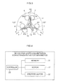
- Fig. 4 is a block diagram illustrating the device for switching between conveyance paths for paper sheets or the like.
- a controller 30 shown in Fig. 4 controls operations of the respective sections in accordance with a control program stored in a memory 31.
- the memory 31 memorizes, in addition to the stored control program, results of processing by the controller 30 and the like. Operation of the structure described above is described.
- the controller 30 causes the first blade 11 of the conveyance path switching blade 10 to be disposed at position PA.
- the unillustrated conveyance paths leading from the branch section 2 are provided in the radial pattern with intervals of 120°.
- the first blade 11 and the second blade 12 of the conveyance path switching blade 10 are constructed with an interval of approximately 140°. Therefore, when the first blade 11 is disposed at position PA, the second blade 12 is disposed at position PD. Therefore, banknotes guided by the first blade 11 and the second blade 12 of the conveyance path switching blade 10 may be conveyed from direction a to direction b or from direction b to direction a.
- Fig. 5 is an explanatory diagram illustrating a state in which the first blade has been moved from position PA to position P13. From the state in which banknotes are conveyed between direction a and direction b, when switching so as to convey banknotes between direction a and direction c, the controller 30 drives the stepper motor 22 and, via the motor gear 21 b, the gear 21 a and the blade shaft 20, rotates the conveyance path switching blade 10, in the counterclockwise direction as illustrated in Fig. 5 , and moves it from position PA to position PB as illustrated in Fig. 5 .
- the first blade 11 of the conveyance path switching blade 10 traverses the conveyance path in direction a and is disposed at the opposite side, of sides sandwiching that conveyance path, from the side of the original position. Therefore, because the switching angle of the conveyance path switching blade 10 is small, the stepper motor 22 is rapidly rotated at a first predetermined speed to rotate the conveyance path switching blade 10.
- FIG. 6 is an explanatory diagram illustrating a state in which the first blade has been moved from position PB to position PC.
- the controller 30 drives the stepper motor 22 and, via the motor gear 21b, the gear 21a and the blade shaft 20, rotates the conveyance path switching blade 10 sin the counterclockwise direction and moves it from position PB to position PC as illustrated in Fig. 6 .
- the first blade 11 rotates from the vicinity of the conveyance path in direction a to a vicinity of the conveyance path in direction b. Therefore, the switching angle of the conveyance path switching blade 10 is large,
- the switching of the conveyance path switching blade 10 by the stepper motor 22 is performed at the first predetermined speed, there is a high possibility of operational problems due to loss of synchronization or the like.
- the switching is performed at a second predetermined speed, which is slower than when the switching angle is small.
- the first blade 11 is disposed at position PC
- the second blade 12 is disposed at position PF.
- banknotes may be passed between direction b and direction c.
- Fig. 7 is an explanatory diagram illustrating a state in which the first blade has been moved from position PC to position PD.
- the controller 30 drives the stepper motor 22 and, via the motor gear 21b, the gear 21a and the blade shaft 20, rotates the conveyance path switching blade 10 in the counterclockwise direction and moves it from position PC to position PD as illustrated in Fig. 7 . Going from position PC to position PD, the first blade 11 traverses the conveyance path in direction b and rotates to the opposite side of sides sandwiching that conveyance path. Therefore, because the switching angle of the conveyance path switching blade 10 is small, the stepper motor 22 is rapidly rotated at the first predetermined speed (a high speed) and switches the conveyance path switching blade 10.
- FIG. 8 is an explanatory diagram illustrating a state in which the first blade has been moved from position PD to position PE. From the state in which banknotes are conveyed between direction a and direction b, when switching so as to convey banknotes between direction a and direction c, the controller 30 drives the stepper motor 22 and, via the motor gear 21b, the gear 21a and the blade shaft 20, rotates the conveyance path switching blade 10 in the counterclockwise direction and moves it from position PD to position PE as illustrated in Fig. 8 .
- the first blade 11 rotates from the side of the conveyance path in direction b to the side of the conveyance path in direction c. Therefore, because the switching angle of the conveyance path switching blade 10 is large, the conveyance path switching blade 10 is switched by the stepper motor 22 in the same manner as when being switched from position PB to position PC. Hence, when the first blade 11 is disposed at position PE, the second blade 12 is disposed at position PB. Thus, banknotes may be passed between direction a and direction c.
- Fig. 9 is an explanatory diagram illustrating a state in which the first blade has been moved from position PE to position PF.
- the controller 30 drives the stepper motor 22 and, via the motor gear 2 1 b, the gear 21a and the blade shaft 20, rotates the conveyance path switching blade 10 in the counterclockwise direction and moves it from position PE to position PF as illustrated in Fig. 8 .
- the first blade 11 traverses the conveyance path in direction c and rotates to the opposite side of sides sandwiching that conveyance path. Therefore, because the switching angle of the conveyance path switching blade 10 is small, the stepper motor 22 is rotated in the same manner as described above and switches the conveyance path switching blade 10. Hence, when the first blade 11 is disposed at position PB, the third blade 13 is disposed at position PC. Thus, banknotes may be passed between direction b and direction c.
- the conveyance path switching blade 10 is described as being rotated in the counterclockwise direction, but may be rotated in the clockwise direction.
- the first blade 11 when the first blade 11 is located at position PA, if the conveyance direction is to be switched such that banknotes are conveyed between direction b and direction c, the first blade 11 may be disposed from position PA to position PF by the conveyance path switching blade 10 being rotated in the clockwise direction.
- the conveyance path switching blade formed of the first blade, the second blade and the third blade is provided in a device for switching between conveyance paths for banknotes, and this conveyance path switching blade is rotated by a stepper motor and switches the conveyance direction of banknotes.
- the conveyance direction of banknotes may be switched with a single drive source. Consequently, the device for switching between conveyance paths for banknotes may be made small sized. Furthermore, because there is a single drive source, the device for switching between conveyance paths for banknotes may be fabricated at a lower price.
- a switching angle of the conveyance path switching blade When a switching angle of the conveyance path switching blade is small to an extent in which the first blade traverses a conveyance path and is disposed at the opposite side, the stepper motor is rapidly rotated. Therefore, the conveyance direction may be switched promptly so as not to lose synchronization, and an effect is provided in that a lengthening of the duration taken for switching is prevented.
- the above description is an example in which a plural number of conveyance path switching blades are fixed to a blade shaft. However, if integrally fabricated, for example, by resin molding, the respective conveyance path switching blades may be joined as illustrated in Fig. 10.
- Fig. 10 is an explanatory diagram illustrating a rib shape between the conveyance path switching blades.
- the shape of a rib 10a between the conveyance path switching blades may be a shape whose cross-section is pentagonal as illustrated in Fig. 10 .
Landscapes
- Engineering & Computer Science (AREA)
- Mechanical Engineering (AREA)
- Separation, Sorting, Adjustment, Or Bending Of Sheets To Be Conveyed (AREA)
Abstract
Description
- The present invention relates to a device for switching between conveyance paths for paper sheets or the like, which is provided in a device or the like for handling paper sheets or the like and is for switching conveyance directions of banknotes.
- A related art device for switching between conveyance paths for paper sheets or the like switches conveyance directions of banknotes between three directions by conveying and guiding the banknotes, which serve as an example of the paper sheets or the like, while driving solenoids of two types: a solenoid that serves as a drive source that drives a gate for switching a conveyance direction from one conveyance path to another conveyance path; and a solenoid that serves as a drive source that drives a stopping member for stopping rotation of the gate (for example, see paragraph [0013] and
Fig. 1 of Japanese Patent Application Laid-Open (JP-A) No.2006-213528 - However, in the related art described above, because two drive sources are used to change the conveyance direction of the paper sheets or the like (banknotes), the device for switching between conveyance paths for paper sheets or the like is larger.
The present invention provides a means for solving this issue. - One aspect of the present invention is a device for switching between conveyance paths for paper sheets or the like, including a conveyance path switching blade provided at a branch section at which conveyance paths branch in three directions, the conveyance path switching blade rotating to perform a switching operation for guiding paper sheets or the like sent from any one of the conveyance paths to either of the other two conveyance paths. The branch section is constructed so as to extend in three directions, the conveyance path switching blade includes guide sections that protrude in three directions from a center of the rotation, angles formed between one of the guide sections and the other two of the guide sections are larger than an angle formed between two of the conveyance paths, and the conveyance path switching blade is rotated by a motor.
- Thus, the present invention is provided with the conveyance path switching blade provided with the three protruding guide sections, and this conveyance path switching blade is rotated by a stepper motor. Therefore, there may be a single drive source and the device may be made small.
-
-
Fig. 1 is an explanatory diagram illustrating a device for switching between conveyance paths for paper sheets or the like of an exemplary embodiment. -
Fig. 2 is an explanatory diagram illustrating a state in which a branch section and conveyance path switching blades are arrayed. -
Fig. 3 is an explanatory diagram illustrating a state in which the device for switching between conveyance paths for paper sheets or the like is viewed in an axial direction. -
Fig. 4 is a block diagram illustrating the device for switching between conveyance paths for paper sheets or the like. -
Fig. 5 is an explanatory diagram illustrating a state in which a first blade has been moved from position PA to position PB. -
Fig. 6 is an explanatory diagram illustrating a state in which the first blade has been moved from position PB to position PC. -
Fig. 7 is an explanatory diagram illustrating a state in which the first blade has been moved from position PC to position PD. -
Fig. 8 is an explanatory diagram illustrating a state in which the first blade has been moved from position PD to position PE. -
Fig. 9 is an explanatory diagram illustrating a state in which the first blade has been moved from position PE to position PF. -
Fig. 10 is an explanatory diagram illustrating a rib shape between the conveyance path switching blades. - Herebelow, an exemplary embodiment of a device for switching between conveyance paths for paper sheets or the like according to the present invention is described with reference to the drawing.
-
Fig. 1 is an explanatory diagram illustrating the device for switching between conveyance paths for paper sheets or the like of the exemplary embodiment.
Fig. 1 shows a device 1 for switching between conveyance paths for paper sheets or the like and describes an example in which banknotes serve as the paper sheets or the like.
A branch section 2 is formed of three curved banknote guides 3, 4 and 5. The banknote guides 3, 4 and 5 are arrayed in a substantially triangular shape with gaps of a size through which banknotes may pass. Thus, the branch section 2 guides banknotes, which are conveyed along unillustrated banknote conveyance paths and whose conveyance directions are to be switched. - Cutouts (square holes in the drawings) are provided at pairs of locations of each of the banknote guides 3, 4 and 5.
The positions of the cutouts are, as illustrated inFig. 1 , a location of the banknote guide 3 that opposes the banknote guide 4 and a location that opposes the banknote guide 5. The cutouts provided in the banknote guide 4 are at a location that opposes the banknote guide 3 and a location that opposes the banknote guide 5. The cutout at the location that opposes the banknote guide 3 has its position set so as to be disposed to oppose the cutout in the banknote guide 3 that is provided at the location opposing the banknote guide 4. - The positions of the cutouts provided in the banknote guide 5 are at locations that oppose the banknote guides 3 and 4 and are disposed to oppose the cutouts provided in the banknote guides 3 and 4.
Feed rollers 6 are mounted so as to protrude into the gaps of the branch section 2 through the cutouts provided in the banknote guide 3 and the cutouts at the locations of the banknote guide 4 that oppose the banknote guide 5. - The shapes of these cutouts are not to be limited to square holes; they may be flat oval holes or the like.
Press rollers 7 protrude into the gaps of the branch section 2 through the cutouts at the locations of the banknote guide 4 that oppose the banknote guide 3 and the cutouts in the banknote guide 5. Thus, the press rollers 7 are disposed to oppose thefeed rollers 6 and nip banknotes against thefeed rollers 6.
The cutouts have margins assured so as not to interfere with thefeed rollers 6. - Conveyance paths extend in three directions from the branch section 2 of the present exemplary embodiment. These conveyance paths are provided in a radial pattern with intervals of 120°. Accordingly, the pairs of
feed rollers 6 and press rollers 7 are arrayed at equal angles of 120° each.
A conveyancepath switching blade 10 is provided in line with the banknote guides 3, 4 and 5 along an axial direction of thefeed rollers 6 and press rollers 7. The conveyancepath switching blade 10 includes guide sections that protrude in three directions from a center of rotation. One of these guide sections is afirst blade 11. The conveyancepath switching blade 10 is constructed such that angles formed between thefirst blade 11 and the other guide sections (asecond blade 12 and a third blade 13) are larger (for example, 150°) than at least the angles formed between pairs of the conveyance paths extending from the branch section 2. - Thus, the conveyance
path switching blade 10 functions so as to guide banknotes that are conveyed from one of the conveyance paths while switching the conveyance direction toward either conveyance path of the other two conveyance paths. Here, a curved face is formed from thefirst blade 11 to thesecond blade 12 or thethird blade 13, and this curved face acts as a guide surface for the banknotes.
So that the conveyancepath switching blade 10 and the banknote guides 3, 4 and 5 do not interfere, cutouts formed as, for example, square holes are provided in the banknote guides 3, 4 and 5, and other structural components and the like are not disposed in a rotation track of the conveyancepath switching blade 10. -
Fig. 2 is an explanatory diagram illustrating a state in which the branch section and the conveyance path switching blades are arrayed.
Fig. 2 is shown in a state in which the branch section 2 is not illustrated.
InFig. 2 ,toothed pulleys 15 are provided at one end of shafts, partways along which shafts thefeed rollers 6 are mounted.
Thefeed rollers 6 of the present exemplary embodiment are provided at the cutouts of the banknote guide 3 and the cutouts of the banknote guide 4. Accordingly, there are three shafts and they are independently rotated, Thetoothed pulleys 15 are mounted so as to be fixed to two shafts, as illustrated inFig. 2 . - A
toothed belt 16 is sound round thetoothed pulleys 15. When one of thetoothed pulleys 15 is rotated by driving of amotor 17 mounted at one end of one of the shafts, the rotation is transmitted to and rotates the other of thetoothed pulleys 15 via thetoothed belt 16.
Only one of themotor 17 is illustrated for the present exemplary embodiment, but this is not to be limiting, It is sufficient that thefeed rollers 6 can be rotated in directions to be capable of conveying banknotes both ways between direction a and direction b illustrated inFig. 3 , and between direction b and direction c and between direction c and direction a. Motors may accordingly be provided at the respective shafts. - A
blade shaft 20 is provided so as to pass through a center of point symmetry of the branch section 2. The conveyancepath switching blade 10 is plurally attached partways along theblade shaft 20.
Ablade rotating mechanism 21 is formed of agear 21a attached to one end of theblade shaft 20, amotor gear 21b provided so as to mesh with thegear 21a, and astepper motor 22 that rotates themotor gear 21b. Driving of thestepper motor 22 is transmitted to theblade shaft 20 via themotor gear 21b and thegear 21a, and thus the conveyancepath switching blades 10 rotate in forward and reverse directions. - A
slit disc 25 is fixed to the other end of theblade shaft 20. Ahome position sensor 26 is also attached. Thus, theslit disc 25 functions to implement positioning of thefirst blade 11 of the conveyancepath switching blade 10, which rotates together with theblade shaft 20.
The banknote guides 3, 4 and 5,motor 17,home position sensor 26 and the like described above are supported by an unillustrated frame. The shafts of thefeed rollers 6, theblade shaft 20 and the like are similarly rotatably supported by the frame. -
Fig. 3 is an explanatory diagram illustrating a state in which the device for switching between conveyance paths for paper sheets or the like is viewed in the axial direction of the conveyance path switching blade.
Predetermined positions of thefirst blade 11 are set. These positions are positions in which, as illustrated inFig. 3 , thefirst blade 11 is arrayed in the axial direction with any of thefeed rollers 6 and press rollers 7 or the like.
As illustrated inFig. 3 , a position at which thefirst blade 11 is arrayed with the press rollers 7 that protrude into the gaps of the branch section 2 through the cutouts in the banknote guide 4 that oppose the banknote guide 3 is a position PA, and a position at which thefirst blade 11 is arrayed with thefeed rollers 6 that are disposed to oppose the press rollers 7 at position PA and provided at the banknote guide 3 is a position PB. - A position at which the
first blade 11 is arrayed with thefeed rollers 6 that are provided at the locations of the banknote guide 3 that oppose the banknote guide 4 is a position PC, and a position at which thefirst blade 11 is arrayed with the press rollers 7 that are disposed to oppose thefeed rollers 6 at position PC and provided at the banknote guide 4 is a position PD.
A position at which thefirst blade 11 is arrayed with thefeed rollers 6 that are provided at the locations of the banknote guide 5 that oppose the banknote guide 4 is a position PE, and a position at which thefirst blade 11 is arrayed with the press rollers 7 that are disposed to oppose thefeed rollers 6 at position PE and provided at the banknote guide 5 is a position PF. - Therefore, switching angles when the
first blade 11 of the conveyancepath switching blade 10 moves through any of between positions PA and PB, between positions PC and PD, and between positions PE and PF are small, and switching angles when thefirst blade 11 moves through any of between positions PB and PC, between positions PA and PF, and between positions PD and PE are large.
The conveyancepath switching blade 10 may be switched (rotated) between any of the above-mentioned positions. - Given this, the conveyance
path switching blade 10 may switch and convey banknotes entering from the direction of any of arrow a, arrow b and arrow c inFig. 3 to another of the conveyance directions.
Fig. 4 is a block diagram illustrating the device for switching between conveyance paths for paper sheets or the like.
Acontroller 30 shown inFig. 4 controls operations of the respective sections in accordance with a control program stored in amemory 31. - The
memory 31 memorizes, in addition to the stored control program, results of processing by thecontroller 30 and the like.
Operation of the structure described above is described.
When the conveyance direction of banknotes entering the branch section 2 from the direction of arrow a shown inFig. 3 is to be switched to the direction of arrow b, thecontroller 30 causes thefirst blade 11 of the conveyancepath switching blade 10 to be disposed at position PA. - The unillustrated conveyance paths leading from the branch section 2 are provided in the radial pattern with intervals of 120°. In contrast, the
first blade 11 and thesecond blade 12 of the conveyancepath switching blade 10 are constructed with an interval of approximately 140°. Therefore, when thefirst blade 11 is disposed at position PA, thesecond blade 12 is disposed at position PD.
Therefore, banknotes guided by thefirst blade 11 and thesecond blade 12 of the conveyancepath switching blade 10 may be conveyed from direction a to direction b or from direction b to direction a. -
Fig. 5 is an explanatory diagram illustrating a state in which the first blade has been moved from position PA to position P13.
From the state in which banknotes are conveyed between direction a and direction b, when switching so as to convey banknotes between direction a and direction c, thecontroller 30 drives thestepper motor 22 and, via themotor gear 21 b, thegear 21 a and theblade shaft 20, rotates the conveyancepath switching blade 10, in the counterclockwise direction as illustrated inFig. 5 , and moves it from position PA to position PB as illustrated inFig. 5 . - At this time, from position PA, the
first blade 11 of the conveyancepath switching blade 10 traverses the conveyance path in direction a and is disposed at the opposite side, of sides sandwiching that conveyance path, from the side of the original position.
Therefore, because the switching angle of the conveyancepath switching blade 10 is small, thestepper motor 22 is rapidly rotated at a first predetermined speed to rotate the conveyancepath switching blade 10. - When the
first blade 11 is disposed at position PB, the third blade is disposed at position PE. Therefore, banknotes entering from direction a are guided to direction c by the conveyancepath switching blade 10.
Thus, banknotes may be passed either way between direction a and direction c.
Fig. 6 is an explanatory diagram illustrating a state in which the first blade has been moved from position PB to position PC. - From the state in which banknotes are conveyed between direction a and direction c, when switching so as to convey banknotes between direction b and direction c, the
controller 30 drives thestepper motor 22 and, via themotor gear 21b, thegear 21a and theblade shaft 20, rotates the conveyancepath switching blade 10 sin the counterclockwise direction and moves it from position PB to position PC as illustrated inFig. 6 .
At this time, going from position PB to position PC, thefirst blade 11 rotates from the vicinity of the conveyance path in direction a to a vicinity of the conveyance path in direction b. Therefore, the switching angle of the conveyancepath switching blade 10 is large, - Therefore, if the switching of the conveyance
path switching blade 10 by thestepper motor 22 is performed at the first predetermined speed, there is a high possibility of operational problems due to loss of synchronization or the like. Thus, rather than the switching being performed at the relatively fast first predetermined speed, the switching is performed at a second predetermined speed, which is slower than when the switching angle is small.
Hence, when thefirst blade 11 is disposed at position PC, thesecond blade 12 is disposed at position PF. Thus, banknotes may be passed between direction b and direction c. - Herein, control is performed as fast as possible depending on rise control when starting the
stepper motor 22 and fall control when stopping the same, and also acceleration control and the like. The various settings thereof may be suitably specified in accordance with well-known technologies.
Fig. 7 is an explanatory diagram illustrating a state in which the first blade has been moved from position PC to position PD. - From the state in which banknotes are conveyed between direction b and direction c, when switching so as to convey banknotes between direction a and direction b, the
controller 30 drives thestepper motor 22 and, via themotor gear 21b, thegear 21a and theblade shaft 20, rotates the conveyancepath switching blade 10 in the counterclockwise direction and moves it from position PC to position PD as illustrated inFig. 7 .
Going from position PC to position PD, thefirst blade 11 traverses the conveyance path in direction b and rotates to the opposite side of sides sandwiching that conveyance path. Therefore, because the switching angle of the conveyancepath switching blade 10 is small, thestepper motor 22 is rapidly rotated at the first predetermined speed (a high speed) and switches the conveyancepath switching blade 10. - Hence, when the
first blade 11 is disposed at position PD, thethird blade 13 is disposed at position PA. Thus, banknotes may be passed between direction a and direction b.
Fig. 8 is an explanatory diagram illustrating a state in which the first blade has been moved from position PD to position PE.
From the state in which banknotes are conveyed between direction a and direction b, when switching so as to convey banknotes between direction a and direction c, thecontroller 30 drives thestepper motor 22 and, via themotor gear 21b, thegear 21a and theblade shaft 20, rotates the conveyancepath switching blade 10 in the counterclockwise direction and moves it from position PD to position PE as illustrated inFig. 8 . - Going from position PD to position PE, the
first blade 11 rotates from the side of the conveyance path in direction b to the side of the conveyance path in direction c. Therefore, because the switching angle of the conveyancepath switching blade 10 is large, the conveyancepath switching blade 10 is switched by thestepper motor 22 in the same manner as when being switched from position PB to position PC.
Hence, when thefirst blade 11 is disposed at position PE, thesecond blade 12 is disposed at position PB. Thus, banknotes may be passed between direction a and direction c. -
Fig. 9 is an explanatory diagram illustrating a state in which the first blade has been moved from position PE to position PF.
From the state in which banknotes are conveyed between direction a and direction c, when switching so as to convey banknotes between direction b and direction c, thecontroller 30 drives thestepper motor 22 and, via the motor gear 2 1 b, thegear 21a and theblade shaft 20, rotates the conveyancepath switching blade 10 in the counterclockwise direction and moves it from position PE to position PF as illustrated inFig. 8 . - At this time, going from position PE to position OF, the
first blade 11 traverses the conveyance path in direction c and rotates to the opposite side of sides sandwiching that conveyance path. Therefore, because the switching angle of the conveyancepath switching blade 10 is small, thestepper motor 22 is rotated in the same manner as described above and switches the conveyancepath switching blade 10.
Hence, when thefirst blade 11 is disposed at position PB, thethird blade 13 is disposed at position PC. Thus, banknotes may be passed between direction b and direction c. - In the switching of conveyance directions described above, the conveyance
path switching blade 10 is described as being rotated in the counterclockwise direction, but may be rotated in the clockwise direction. For example, when thefirst blade 11 is located at position PA, if the conveyance direction is to be switched such that banknotes are conveyed between direction b and direction c, thefirst blade 11 may be disposed from position PA to position PF by the conveyancepath switching blade 10 being rotated in the clockwise direction. - As described hereabove, in the present exemplary embodiment, the conveyance path switching blade formed of the first blade, the second blade and the third blade is provided in a device for switching between conveyance paths for banknotes, and this conveyance path switching blade is rotated by a stepper motor and switches the conveyance direction of banknotes. Thus, the conveyance direction of banknotes may be switched with a single drive source. Consequently, the device for switching between conveyance paths for banknotes may be made small sized.
Furthermore, because there is a single drive source, the device for switching between conveyance paths for banknotes may be fabricated at a lower price. - When a switching angle of the conveyance path switching blade is small to an extent in which the first blade traverses a conveyance path and is disposed at the opposite side, the stepper motor is rapidly rotated. Therefore, the conveyance direction may be switched promptly so as not to lose synchronization, and an effect is provided in that a lengthening of the duration taken for switching is prevented.
The above description is an example in which a plural number of conveyance path switching blades are fixed to a blade shaft. However, if integrally fabricated, for example, by resin molding, the respective conveyance path switching blades may be joined as illustrated inFig. 10. Fig. 10 is an explanatory diagram illustrating a rib shape between the conveyance path switching blades. The shape of arib 10a between the conveyance path switching blades may be a shape whose cross-section is pentagonal as illustrated inFig. 10 .
Claims (4)
- A device for switching between conveyance paths for paper sheets or the like, comprising:a conveyance path switching blade provided at a branch section at which conveyance paths branch in three directions, the conveyance path switching blade rotating to perform a switching operation for guiding paper sheets or the like sent from any one of the conveyance paths to either of the other two conveyance paths,wherein the branch section is constructed so as to extend in three directions, andthe conveyance path switching blade includes guide sections that protrude in three directions from a center of the rotation, angles formed between one of the guide sections and the other two of the guide sections are larger than an angle formed between two of the conveyance paths, and the conveyance path switching blade is rotated by a motor
- The device for switching between conveyance paths for paper sheets or the like according to claim 1, wherein
the one of the guide portions of the conveyance path switching blade is a first blade and the other two of the guide portions are a second blade and a third blade, and guide surfaces for paper sheets or the like are structured from the first blade to the second blade and the third blade,
and, when the conveyance path switching blade is to be rotated and disposed such that the guide surface guides paper sheets or the like between conveyance paths, the device for switching between conveyance paths for paper sheets or the like changes a speed of the rotation between a case in which the first blade traverses the conveyance path closest to a position before the rotation and is disposed at an opposite side of this conveyance, path and a case in which the first blade is rotated to move to a position in a vicinity of a conveyance path other than the conveyance path closest to the position before the rotation. - The device for switching between conveyance paths for paper sheets or the like according to claim 1, wherein the motor is a stepper motor.
- The device for switching between conveyance paths for paper sheets or the like according to claim 2, wherein the speed in the case in which the first blade traverses the conveyance path closest to the position before the rotation and is disposed at the opposite side of this conveyance path is a higher speed than the speed in the case in which the first blade is rotated to move to a position in the vicinity of a conveyance path other than the conveyance path closest to the position before the rotation.
Applications Claiming Priority (2)
| Application Number | Priority Date | Filing Date | Title |
|---|---|---|---|
| JP2008102956A JP2009249174A (en) | 2008-04-10 | 2008-04-10 | Paper sheet carrying switching device |
| PCT/JP2009/050345 WO2009125613A1 (en) | 2008-04-10 | 2009-01-14 | Device for switching between conveyance paths for paper sheets or the like |
Publications (2)
| Publication Number | Publication Date |
|---|---|
| EP2277813A1 true EP2277813A1 (en) | 2011-01-26 |
| EP2277813A4 EP2277813A4 (en) | 2017-10-18 |
Family
ID=41161749
Family Applications (1)
| Application Number | Title | Priority Date | Filing Date |
|---|---|---|---|
| EP09729360.9A Withdrawn EP2277813A4 (en) | 2008-04-10 | 2009-01-14 | Device for switching between conveyance paths for paper sheets or the like |
Country Status (5)
| Country | Link |
|---|---|
| EP (1) | EP2277813A4 (en) |
| JP (1) | JP2009249174A (en) |
| KR (1) | KR101473047B1 (en) |
| CN (2) | CN103359524B (en) |
| WO (1) | WO2009125613A1 (en) |
Cited By (1)
| Publication number | Priority date | Publication date | Assignee | Title |
|---|---|---|---|---|
| WO2020027717A1 (en) * | 2018-08-03 | 2020-02-06 | Suzohapp Canada Ulc | A banknote handling machine |
Families Citing this family (25)
| Publication number | Priority date | Publication date | Assignee | Title |
|---|---|---|---|---|
| DE102009052040A1 (en) * | 2009-11-05 | 2011-05-12 | Wincor Nixdorf International Gmbh | Device for handling notes of value |
| JP5647798B2 (en) * | 2010-02-26 | 2015-01-07 | 日立オムロンターミナルソリューションズ株式会社 | Paper handling equipment |
| CN102254368B (en) * | 2011-04-13 | 2013-09-25 | 广州广电运通金融电子股份有限公司 | Guider for conveying flaky objects |
| CN102139818B (en) * | 2011-04-13 | 2013-03-06 | 广州广电运通金融电子股份有限公司 | Guider for conveying sheets |
| JP2013041451A (en) * | 2011-08-17 | 2013-02-28 | Oki Electric Ind Co Ltd | Sheet paper conveyance device and automatic teller machine |
| KR101886438B1 (en) * | 2012-06-13 | 2018-08-07 | 효성티앤에스 주식회사 | Apparatus for changing of the bill transferring direction and apparatus for bill receiving and dispensing having thereof |
| CN103318685B (en) * | 2013-07-05 | 2016-01-20 | 广州广电运通金融电子股份有限公司 | A kind of Sheet medium transmission passage reversing arrangement |
| JP6405928B2 (en) * | 2014-11-14 | 2018-10-17 | 沖電気工業株式会社 | Actuator and medium transaction device |
| JP6413688B2 (en) * | 2014-11-18 | 2018-10-31 | 沖電気工業株式会社 | Automatic transaction equipment |
| JP6380039B2 (en) * | 2014-11-20 | 2018-08-29 | 沖電気工業株式会社 | Transport path switching device and medium transaction device |
| KR102312912B1 (en) * | 2015-02-10 | 2021-10-15 | 효성티앤에스 주식회사 | Apparatus for changing of the bill transferring direction in automated teller machine |
| JP6381129B2 (en) * | 2015-02-13 | 2018-08-29 | ローレルバンクマシン株式会社 | Paper sheet transfer switching device |
| KR20160130673A (en) | 2015-05-04 | 2016-11-14 | 농업회사법인 (주)썬드림 | Method for inhibiting browning of fruits and vegetables |
| JP6651738B2 (en) * | 2015-08-24 | 2020-02-19 | 沖電気工業株式会社 | Transfer direction switching device and medium handling device |
| JP6637315B2 (en) * | 2016-01-13 | 2020-01-29 | ローレル精機株式会社 | Sheet conveyance direction switching device |
| CN106204909A (en) * | 2016-07-13 | 2016-12-07 | 深圳怡化电脑股份有限公司 | A kind of bank note direction switching device and automatic teller machine |
| CN106297071A (en) * | 2016-07-27 | 2017-01-04 | 深圳怡化电脑股份有限公司 | Bank note switching device |
| JP6823978B2 (en) * | 2016-09-12 | 2021-02-03 | 日立オムロンターミナルソリューションズ株式会社 | Paper leaf handling equipment, automated teller machines and paper leaf handling methods |
| CN106373261B (en) * | 2016-10-17 | 2022-08-30 | 深圳怡化电脑股份有限公司 | Banknote guide device |
| CN108665608B (en) * | 2017-04-01 | 2020-11-20 | 山东新北洋信息技术股份有限公司 | Channel switching mechanism and paper money processing device |
| CN107324088B (en) * | 2017-07-03 | 2023-11-10 | 深圳怡化电脑股份有限公司 | Paper reversing device and paper conveying equipment |
| CN107499977A (en) * | 2017-08-14 | 2017-12-22 | 昆山古鳌电子机械有限公司 | A kind of paper processing device |
| CN107845189B (en) * | 2017-11-16 | 2023-09-12 | 深圳怡化电脑股份有限公司 | Paper money conveying path switching method and device for automatic teller machine |
| JP7035563B2 (en) | 2018-01-26 | 2022-03-15 | 沖電気工業株式会社 | Media processing equipment and automated teller machines |
| JP2021105894A (en) * | 2019-12-27 | 2021-07-26 | グローリー株式会社 | Paper sheet processing device |
Family Cites Families (9)
| Publication number | Priority date | Publication date | Assignee | Title |
|---|---|---|---|---|
| JP2742205B2 (en) * | 1993-12-24 | 1998-04-22 | 甲府日本電気株式会社 | Paper sheet transfer and branching mechanism |
| JP2000072306A (en) * | 1998-08-31 | 2000-03-07 | Canon Inc | Sheet reversing discharge device and image forming apparatus provided with the device |
| JP3740432B2 (en) * | 2002-04-16 | 2006-02-01 | キヤノン株式会社 | Sheet guide apparatus at intersection of guide path and image forming apparatus provided with the apparatus |
| JP2006219207A (en) * | 2005-02-08 | 2006-08-24 | Kyocera Mita Corp | Paper guide device of image forming apparatus |
| JP4598591B2 (en) * | 2005-04-28 | 2010-12-15 | 京セラミタ株式会社 | Paper transport branch device |
| JP2007076794A (en) * | 2005-09-13 | 2007-03-29 | Toshiba Corp | Gate switching device |
| JP2006213528A (en) * | 2006-05-17 | 2006-08-17 | Hitachi Omron Terminal Solutions Corp | Paper sheet transport direction switching device |
| CN101081668B (en) * | 2006-05-29 | 2010-10-13 | 株式会社理光 | Sheet conveying path switching device used in image forming apparatus, and sheet conveying device |
| JP5172257B2 (en) * | 2007-09-12 | 2013-03-27 | グローリー株式会社 | Paper sheet branching mechanism, paper sheet processing apparatus, and paper sheet branching method |
-
2008
- 2008-04-10 JP JP2008102956A patent/JP2009249174A/en active Pending
-
2009
- 2009-01-14 CN CN201310322196.1A patent/CN103359524B/en active Active
- 2009-01-14 EP EP09729360.9A patent/EP2277813A4/en not_active Withdrawn
- 2009-01-14 WO PCT/JP2009/050345 patent/WO2009125613A1/en not_active Ceased
- 2009-01-14 CN CN200980112174.4A patent/CN101983168B/en active Active
- 2009-01-14 KR KR1020107025159A patent/KR101473047B1/en active Active
Cited By (3)
| Publication number | Priority date | Publication date | Assignee | Title |
|---|---|---|---|---|
| WO2020027717A1 (en) * | 2018-08-03 | 2020-02-06 | Suzohapp Canada Ulc | A banknote handling machine |
| US12062259B2 (en) | 2018-08-03 | 2024-08-13 | Suzohapp Canada Ulc | Banknote handling machine |
| US12494103B2 (en) | 2018-08-03 | 2025-12-09 | Suzohapp Canada Ulc | Banknote handling machine |
Also Published As
| Publication number | Publication date |
|---|---|
| CN101983168B (en) | 2014-01-29 |
| CN101983168A (en) | 2011-03-02 |
| EP2277813A4 (en) | 2017-10-18 |
| WO2009125613A1 (en) | 2009-10-15 |
| CN103359524A (en) | 2013-10-23 |
| CN103359524B (en) | 2016-01-13 |
| JP2009249174A (en) | 2009-10-29 |
| KR20100131526A (en) | 2010-12-15 |
| KR101473047B1 (en) | 2014-12-15 |
Similar Documents
| Publication | Publication Date | Title |
|---|---|---|
| CN101983168B (en) | Paper conveying path switching device | |
| CN101772787B (en) | Three-way deflector for diverting sheet-like media | |
| KR100207734B1 (en) | Paper reversing device of duplex printing machine | |
| US5634635A (en) | Automatic document feeder | |
| US20220063950A1 (en) | Sheet processing apparatus | |
| JP5896784B2 (en) | Sheet processing apparatus and image forming apparatus | |
| JP2009208872A (en) | Sheet perforating device, sheet transfer device, sheet processing device, and image forming device | |
| RU2198836C1 (en) | Sheet material turnover device | |
| JP4998298B2 (en) | Media processing device | |
| JP2017185555A (en) | Cutting device | |
| JPH07187470A (en) | Conveyance and branching mechanism for paper sheets | |
| JP2011073797A (en) | Paper sheet obverse and reverse side alignment device | |
| JP5581033B2 (en) | Detachment mechanism for single transfer holder | |
| EP0955156A1 (en) | Device for slitting and creasing a sheet cardboard material | |
| JP6381129B2 (en) | Paper sheet transfer switching device | |
| JP2724829B2 (en) | Paper sheet correction device | |
| US20080122157A1 (en) | Sheet carrying path switching mechanism and sheet folding device | |
| JP2009018913A (en) | Paper processing apparatus and image forming apparatus | |
| JP2010235286A (en) | Document conveying device and image reading device | |
| JP2006213528A (en) | Paper sheet transport direction switching device | |
| JP5176901B2 (en) | Sheet punching apparatus, sheet conveying apparatus, sheet processing apparatus, image forming apparatus, sheet punching method, and computer program | |
| US20120200027A1 (en) | Automatic document feeder | |
| JP4179966B2 (en) | Single conveying type collating machine for paper transport | |
| JPH0656334A (en) | Image recording device finisher | |
| JP2022067917A (en) | Drive transmission device and liquid discharge device |
Legal Events
| Date | Code | Title | Description |
|---|---|---|---|
| PUAI | Public reference made under article 153(3) epc to a published international application that has entered the european phase |
Free format text: ORIGINAL CODE: 0009012 |
|
| 17P | Request for examination filed |
Effective date: 20101110 |
|
| AK | Designated contracting states |
Kind code of ref document: A1 Designated state(s): AT BE BG CH CY CZ DE DK EE ES FI FR GB GR HR HU IE IS IT LI LT LU LV MC MK MT NL NO PL PT RO SE SI SK TR |
|
| AX | Request for extension of the european patent |
Extension state: AL BA RS |
|
| DAX | Request for extension of the european patent (deleted) | ||
| RA4 | Supplementary search report drawn up and despatched (corrected) |
Effective date: 20170920 |
|
| RIC1 | Information provided on ipc code assigned before grant |
Ipc: B65H 29/58 20060101AFI20170914BHEP |
|
| STAA | Information on the status of an ep patent application or granted ep patent |
Free format text: STATUS: THE APPLICATION HAS BEEN WITHDRAWN |
|
| 18W | Application withdrawn |
Effective date: 20180314 |