EP2277727A1 - Stabilizer device and method for manufacturing the same - Google Patents
Stabilizer device and method for manufacturing the same Download PDFInfo
- Publication number
- EP2277727A1 EP2277727A1 EP09733408A EP09733408A EP2277727A1 EP 2277727 A1 EP2277727 A1 EP 2277727A1 EP 09733408 A EP09733408 A EP 09733408A EP 09733408 A EP09733408 A EP 09733408A EP 2277727 A1 EP2277727 A1 EP 2277727A1
- Authority
- EP
- European Patent Office
- Prior art keywords
- preventing member
- stabilizer
- misalignment preventing
- bush
- torsion
- Prior art date
- Legal status (The legal status is an assumption and is not a legal conclusion. Google has not performed a legal analysis and makes no representation as to the accuracy of the status listed.)
- Granted
Links
- 239000003381 stabilizer Substances 0.000 title claims abstract description 122
- 238000000034 method Methods 0.000 title claims description 48
- 238000004519 manufacturing process Methods 0.000 title claims description 15
- 229920005989 resin Polymers 0.000 claims abstract description 25
- 239000011347 resin Substances 0.000 claims abstract description 25
- 238000000576 coating method Methods 0.000 claims description 32
- 238000002347 injection Methods 0.000 claims description 22
- 239000007924 injection Substances 0.000 claims description 22
- 239000000463 material Substances 0.000 claims description 10
- 238000005480 shot peening Methods 0.000 claims description 7
- 230000003247 decreasing effect Effects 0.000 claims description 5
- 238000010438 heat treatment Methods 0.000 claims description 4
- AZDRQVAHHNSJOQ-UHFFFAOYSA-N alumane Chemical group [AlH3] AZDRQVAHHNSJOQ-UHFFFAOYSA-N 0.000 description 22
- 239000011248 coating agent Substances 0.000 description 22
- 238000010586 diagram Methods 0.000 description 16
- XEEYBQQBJWHFJM-UHFFFAOYSA-N Iron Chemical group [Fe] XEEYBQQBJWHFJM-UHFFFAOYSA-N 0.000 description 12
- 230000007246 mechanism Effects 0.000 description 10
- 241001247986 Calotropis procera Species 0.000 description 5
- 239000013585 weight reducing agent Substances 0.000 description 5
- 239000004696 Poly ether ether ketone Substances 0.000 description 4
- 239000004734 Polyphenylene sulfide Substances 0.000 description 4
- 230000002452 interceptive effect Effects 0.000 description 4
- 229920002530 polyetherether ketone Polymers 0.000 description 4
- 229920000069 polyphenylene sulfide Polymers 0.000 description 4
- 238000005452 bending Methods 0.000 description 3
- 239000000470 constituent Substances 0.000 description 3
- 230000000694 effects Effects 0.000 description 3
- 238000005242 forging Methods 0.000 description 3
- 238000013007 heat curing Methods 0.000 description 3
- 230000010355 oscillation Effects 0.000 description 2
- 238000010791 quenching Methods 0.000 description 2
- 230000000171 quenching effect Effects 0.000 description 2
- 230000000452 restraining effect Effects 0.000 description 2
- 239000007787 solid Substances 0.000 description 2
- 238000005482 strain hardening Methods 0.000 description 2
- 239000000725 suspension Substances 0.000 description 2
- 238000005496 tempering Methods 0.000 description 2
- 239000000853 adhesive Substances 0.000 description 1
- 230000001070 adhesive effect Effects 0.000 description 1
- 238000010276 construction Methods 0.000 description 1
- 238000003780 insertion Methods 0.000 description 1
- 230000037431 insertion Effects 0.000 description 1
Images



Classifications
-
- F—MECHANICAL ENGINEERING; LIGHTING; HEATING; WEAPONS; BLASTING
- F16—ENGINEERING ELEMENTS AND UNITS; GENERAL MEASURES FOR PRODUCING AND MAINTAINING EFFECTIVE FUNCTIONING OF MACHINES OR INSTALLATIONS; THERMAL INSULATION IN GENERAL
- F16F—SPRINGS; SHOCK-ABSORBERS; MEANS FOR DAMPING VIBRATION
- F16F1/00—Springs
- F16F1/02—Springs made of steel or other material having low internal friction; Wound, torsion, leaf, cup, ring or the like springs, the material of the spring not being relevant
- F16F1/14—Torsion springs consisting of bars or tubes
- F16F1/16—Attachments or mountings
-
- B—PERFORMING OPERATIONS; TRANSPORTING
- B60—VEHICLES IN GENERAL
- B60G—VEHICLE SUSPENSION ARRANGEMENTS
- B60G21/00—Interconnection systems for two or more resiliently-suspended wheels, e.g. for stabilising a vehicle body with respect to acceleration, deceleration or centrifugal forces
- B60G21/02—Interconnection systems for two or more resiliently-suspended wheels, e.g. for stabilising a vehicle body with respect to acceleration, deceleration or centrifugal forces permanently interconnected
- B60G21/04—Interconnection systems for two or more resiliently-suspended wheels, e.g. for stabilising a vehicle body with respect to acceleration, deceleration or centrifugal forces permanently interconnected mechanically
- B60G21/05—Interconnection systems for two or more resiliently-suspended wheels, e.g. for stabilising a vehicle body with respect to acceleration, deceleration or centrifugal forces permanently interconnected mechanically between wheels on the same axle but on different sides of the vehicle, i.e. the left and right wheel suspensions being interconnected
- B60G21/055—Stabiliser bars
- B60G21/0551—Mounting means therefor
-
- B—PERFORMING OPERATIONS; TRANSPORTING
- B60—VEHICLES IN GENERAL
- B60G—VEHICLE SUSPENSION ARRANGEMENTS
- B60G2204/00—Indexing codes related to suspensions per se or to auxiliary parts
- B60G2204/10—Mounting of suspension elements
- B60G2204/12—Mounting of springs or dampers
- B60G2204/122—Mounting of torsion springs
- B60G2204/1222—Middle mounts of stabiliser on vehicle body or chassis
-
- B—PERFORMING OPERATIONS; TRANSPORTING
- B60—VEHICLES IN GENERAL
- B60G—VEHICLE SUSPENSION ARRANGEMENTS
- B60G2204/00—Indexing codes related to suspensions per se or to auxiliary parts
- B60G2204/40—Auxiliary suspension parts; Adjustment of suspensions
- B60G2204/44—Centering or positioning means
-
- B—PERFORMING OPERATIONS; TRANSPORTING
- B60—VEHICLES IN GENERAL
- B60G—VEHICLE SUSPENSION ARRANGEMENTS
- B60G2204/00—Indexing codes related to suspensions per se or to auxiliary parts
- B60G2204/40—Auxiliary suspension parts; Adjustment of suspensions
- B60G2204/45—Stops limiting travel
-
- Y—GENERAL TAGGING OF NEW TECHNOLOGICAL DEVELOPMENTS; GENERAL TAGGING OF CROSS-SECTIONAL TECHNOLOGIES SPANNING OVER SEVERAL SECTIONS OF THE IPC; TECHNICAL SUBJECTS COVERED BY FORMER USPC CROSS-REFERENCE ART COLLECTIONS [XRACs] AND DIGESTS
- Y10—TECHNICAL SUBJECTS COVERED BY FORMER USPC
- Y10T—TECHNICAL SUBJECTS COVERED BY FORMER US CLASSIFICATION
- Y10T29/00—Metal working
- Y10T29/49—Method of mechanical manufacture
- Y10T29/49616—Structural member making
- Y10T29/49622—Vehicular structural member making
-
- Y—GENERAL TAGGING OF NEW TECHNOLOGICAL DEVELOPMENTS; GENERAL TAGGING OF CROSS-SECTIONAL TECHNOLOGIES SPANNING OVER SEVERAL SECTIONS OF THE IPC; TECHNICAL SUBJECTS COVERED BY FORMER USPC CROSS-REFERENCE ART COLLECTIONS [XRACs] AND DIGESTS
- Y10—TECHNICAL SUBJECTS COVERED BY FORMER USPC
- Y10T—TECHNICAL SUBJECTS COVERED BY FORMER US CLASSIFICATION
- Y10T29/00—Metal working
- Y10T29/49—Method of mechanical manufacture
- Y10T29/4998—Combined manufacture including applying or shaping of fluent material
- Y10T29/49982—Coating
- Y10T29/49986—Subsequent to metal working
Definitions
- the present invention relates to a stabilizer device, which may be mounted on an automobile or the like, and relates to a process for production thereof.
- a stabilizer in the stabilizer device functions as a spring, restraining horizontal oscillation of an automobile body by warping a left arm part and a right arm part in mutually opposing directions, and by contorting a torsion part, when mutually opposing phases in the up and down direction are applied to the suspension mechanisms on the left and right, when an automobile having such a stabilizer device passes through a curve.
- the stabilizer has been fixed to the automobile body by fastening a bracket to an automobile body side with a bolt via a rubber bush arranged on the stabilizer.
- the torsion part and the bush may each resist the frictional force of the other, so that they become misaligned with each other.
- These misaligned parts will not be returned to their original positions even in the case in which a centrifugal force is generated in an opposite direction or in the case in which the automobile then goes straight, and thus the parts would be maintained misaligned from the original positions. Therefore, there may be a problem in which anti-roll effects by the stabilizer cannot be obtained, a problem in which excessive load may be applied on a stabilink fastened on both ends of the stabilizer, and there is a likely problem that the stabilizer may interfere at a circumferential part.
- misalignment preventing member one member for each of the left and right, in total two members, are used per one stabilizer.
- a method for preventing the bush from being misaligned there is a method in which a rubber bush itself is directly fixed to the torsion part by an adhesive or by a heat-curing process.
- a process for production of a hollow stabilizer device having the aluminum ring as the misalignment preventing member first, a forming process in which an electric resistance welded tube cut into a predetermined length is formed into a shape of a stabilizer by a cold-working is performed, next, a heat treatment process in which the half-finished product of the stabilizer is heat-treated by, for example, quenching or tempering is performed, next, shot-peening in which shot is impinged on the half-finished product of the stabilizer is performed, and next, a coating process in which the half-finished product of the stabilizer is coated is performed. After that, the aluminum ring consisting of half portions or two pieces is swaged to obtain the misalignment preventing member.
- an arm part is formed by a bending process of an electric resistance welded tube cut into predetermined length, next, the electric resistance welded tube is bent and is inserted into an iron ring formed into a C-shape, and next, a process in which a flattened part and an attachment hole for attaching a stabilink are formed at an edge part of the arm part by forging or the like is performed. After that, the iron ring is swaged and a coating process is performed.
- the rubber bush is integrally formed at the torsion part of the stabilizer by direct injection, and it is then hardened by a heat curing process.
- Japanese Unexamined Patent Application Publication Nos. 2001-163026 and 2001-165127 may be mentioned.
- the aluminum ring since it is a method for fixing in which an aluminum ring consisting of half portions or two pieces are swaged to the torsion part, the aluminum ring has a connecting part which is a structural weak point. Because of this connecting part, the strength of the aluminum ring is low. Therefore, in the case in which a load is applied to the aluminum ring, the swaged form may be easily broken. Therefore, the fixing strength of the aluminum ring may be easily deteriorated, and fixed positions of the stabilizer at left and right parts of the automobile may become unbalanced. When the automobile passes through a curve, the effects that the stabilizer originally had cannot be sufficiently obtained. As a result, it is not a stabilizer device having sufficient reliability.
- the ring is fixed to the stabilizer via coating. Therefore, it may depend on the coating strength, which is a degree of adhering between the half-finished product of the stabilizer and the coating. Therefore, in the case in which the original coating strength is not obtained, the misalignment preventing member may move with the coating, the fixing strength of which the misalignment preventing member originally has cannot be obtained, and the function as the misalignment preventing member cannot be obtained. As a result, it is not a stabilizer device having sufficient reliability. Furthermore, in the case in which the misalignment preventing member is an aluminum ring or an iron ring, it is heavier than the misalignment preventing member made of resin. Therefore, weight reduction of the stabilizer device cannot be promoted.
- the iron ring since deformation resistance of the iron ring is higher than that of the aluminum ring, the iron ring is formed into a circular shape so as to be swaged easily. Therefore, it is necessary that the torsion part be inserted into the ring before the flattened part and the attaching hole for attaching the stabilink are formed at the edge part of the arm part by forging or the like. That is, it is necessary that the electric resistance welded tube be inserted into the iron ring after bending the electric resistance welded tube and before coating of the half-finished product of the stabilizer. Therefore, handling is difficult since the process for forming the flattened part and attaching hole must be performed while the iron ring is maintained so as not to drop off or fall without swaging it.
- part of the rubber forms burrs and projects from a gap between a shoulder part of a stabilizer and a grip part of a mold supporting the shoulder part of the stabilizer. For example, it has been demonstrated that the burrs are formed even in the case in which the gap is about 0.2 mm. Therefore, a process for removing the burrs is necessary, incurring additional costs.
- an object of the present invention is to provide a stabilizer device having high reliability and which is light in weight.
- the stabilizer device of the present invention has a stabilizer consisting of a torsion part and arm parts each extending from both ends of the torsion part and forming an overall shape of a square bracket, a "]" shape, a bush for fixing the stabilizer to an automobile body arranged at both ends of the torsion part, and a resin misalignment preventing member which has a contacting part contacting with the bush, which is arranged neighboring with the bush, and which is integrally formed with the torsion part while covering all therearound in a predetermined range of an axial direction of the torsion part.
- polyphenylene sulfide, polyetheretherketone or the like is desirable.
- a material such as polyphenylene sulfide or polyetheretherketone if a condition of injection when the misalignment preventing member is directly injected is appropriately selected, generation of burrs can be prevented.
- a material such as polyphenylene sulfide or polyetheretherketone has enough heat resistance and strength to withstand heat in a coating process in which a coating of a stabilizer is dried that is performed after the injection forming process of the misalignment preventing member.
- the misalignment preventing member does not have a connecting part which is a structural weak point, loss of fixing strength at the torsion part of the stabilizer by a load can be prevented, and the bush is maintained at an appropriate position of the torsion part.
- the aluminum ring loses the ability to act as the misalignment preventing member immediately in the case in which load is applied on the aluminum ring, on the other hand, in the case in which the resin misalignment preventing member is misaligned, a load that is required to be misaligned is little changed. Therefore, the misalignment preventing member can maintain the function as the misalignment preventing member, of which the bush is prevented from moving along the axial direction of the torsion part.
- the stabilizer can exhibit the performance preliminarily designed, and the reliability can be increased.
- the misalignment preventing member is made of resin, the weight is lighter than that of an aluminum ring or an iron ring. Therefore, weight reducing of the stabilizer device can be promoted.
- the misalignment preventing member have an inclining part on the contacting part at the opposite side of the bush, whose outer diameter is decreased as it is far from the bush along the axial direction of the torsion part.
- the inclining part can be of a tapered shape, and the cross section shape of the inclining part can be parabolic or circular.
- the misalignment preventing member have plural ribs on the contacting part at the opposite side of the bush, whose outer diameter is decreased as it is far from the bush along the axial direction of the torsion part.
- the inclining part can be a tapered shape, and the cross section shape of the inclining part can be parabolic or circular.
- the load is applied on the bracket arranged on the outer circumference of the bush. If the load is applied like this, the bush is bent toward the misalignment preventing member. In this way, the load is applied to an outer circumferential part of a contacting part of the misalignment preventing member. Therefore, a moment acts in the misalignment preventing member toward the axial direction of the torsion part. That is, the inner circumferential surface of the misalignment preventing member presses the outer circumferential surface of the torsion part, and the load is applied from the misalignment preventing member to the torsion part. Therefore, frictional force between the torsion part and the misalignment preventing member is increased, and further higher frictional force is exhibited. As a result, the bush is prevented from being misaligned, and therefore reliability of the stabilizer device can be increased.
- the misalignment preventing member can be prevented from interfering with surrounding parts of the member, and the cost and the weight can be reduced because of reducing resin used.
- the risk of uneven coating around the misalignment preventing member, which occurs by the misalignment preventing member shielding the coating can be reduced.
- the cost and the weight can be further reduced because of further reducing resin used.
- the misalignment preventing member be formed so as to be 10 mm to 15 mm long in the axial direction of the torsion part.
- the frictional force which can bear against the load generated when contacting the bush and the misalignment preventing member by the centrifugal force generated when the automobile passes through a curve can be exhibited. Therefore, the straight length of the torsion part (excluding the bush) of the stabilizer can be shortened as much as possible, and the stabilizer can be reduced in size. As a result, the weight of the stabilizer can be reduced.
- the misalignment preventing member be formed so as to be 3 mm to 5 mm thick at the thickest portion.
- the misalignment preventing member can be reduced in size, an area in which the contacting part as the misalignment preventing member contacts the bush is maintained. Therefore, the misalignment preventing member can be prevented from interfering with surrounding parts of the member, and the weight of the stabilizer device can be reduced.
- convex and concave portions which prevent misalignment of the torsion part and the misalignment preventing member be arranged on an outer circumferential surface of the torsion part.
- the concave and convex portions methods for reducing roughness by shotblasting or shotpeening, forming dimples, forming projections, forming linear projections, or forming linear grooves may be mentioned. It should be noted that forming the concave and convex part by shotpeening is desirable since the number of processes is increased in the production of the stabilizer device if the dimples, projections, linear projections, and linear grooves are formed.
- the misalignment preventing member can further prevent the bush from moving along the axial direction of the torsion part. As a result, the reliability of the stabilizer can be increased.
- the process for production of the stabilizer device of the present invention has following processes, a forming process in which a bar material is formed into an overall shape of a square bracket, a "]" shape, a heat treatment process in which the half-finished product of the stabilizer is heated, a shot peening process in which shot is impinged on the half-finished product of the stabilizer, an injection forming process in which a misalignment preventing member is integrally formed at shoulder part of the half-finished product of the stabilizer with a resin by direct injection, and a coating process in which the half-finished product of the stabilizer and the misalignment preventing member are coated.
- the misalignment preventing member does not have a connecting part which is a structural weak point, immediate loss of fixing strength at the torsion part of the stabilizer by load can be prevented, and the bush is maintained at an appropriate position of the torsion part.
- the aluminum ring loses the ability as the misalignment preventing member immediately in the case in which load is applied on the aluminum ring, on the other hand, in the case in which the resin misalignment preventing member is misaligned, load required to be misaligned is little changed. Therefore, the misalignment preventing member can maintain the function as the misalignment preventing member, of which the bush is prevented from moving along the axial direction of the torsion part.
- the stabilizer can exhibit the performance preliminarily designed, and the reliability can be increased.
- the misalignment preventing member is made of resin, the weight is lighter than that of an aluminum ring or an iron ring. Therefore, weight reduction of the stabilizer device can be promoted.
- the coating process is performed after the misalignment preventing member is integrally formed, the misalignment preventing member is not fixed to the shoulder part via the coating (meaning fixed directly), the fixing strength of the misalignment preventing member is not affected by the coating strength which is a degree of coating adhering to the half-finished product of the stabilizer. Therefore, even in the case in which the original coating strength is not obtained, the misalignment preventing member does not move together with the coating, the fixing strength of the misalignment preventing member can be obtained, and the function as the misalignment preventing member can be exhibited sufficiently.
- the mold has a cavity for forming the misalignment preventing member in predetermined shape and has a grip part being arranged so as to be continuous with the cavity and supporting the shoulder part of the half-finished product of the stabilizer, and in addition, a gap between the shoulder part and the grip part is not more than 0.6 mm during the direct injection.
- resin filled in the cavity does not flow from the cavity into the grip part, and burrs are not generated.
- the stabilizer device can be produced at low cost.
- a stabilizer having high reliability and light weight can be produced.
- Stabilizer device 10: Automobile body, 100: Stabilizer, 110: Torsion part, 111: Convex and concave part, 300: Bush, 400: Misalignment preventing member, 410: Contacting part, 420: Tapered part, 520: Parabolic part, 620: Rib, 720: Rib, 810: Mold, 820: Cavity, 830: Grip part.
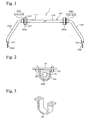
- Fig. 1 is a diagram showing the stabilizer device.
- Fig. 2 is a cross sectional view seen from line Z-Z in Fig. 1 showing a condition being fixed to an automobile body.
- Fig. 3 is an oblique view showing the bracket.
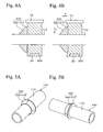
- Fig. 4 is a cross sectional view showing a circumference of the misalignment preventing member enlarged.
- Fig. 4A is a diagram showing a condition in which centrifugal force is not generated.
- Fig. 4B is a diagram showing a condition in which centrifugal force is generated.
- Fig. 5 is an oblique view showing the misalignment preventing member.
- Fig. 1 is a diagram showing the stabilizer device.
- Fig. 2 is a cross sectional view seen from line Z-Z in Fig. 1 showing a condition being fixed to an automobile body.
- Fig. 3 is an oblique view showing the bracket.
- Fig. 4 is a cross sectional view showing a
- FIG. 6 is a diagram showing the embodiment in which the misalignment preventing member is arranged inside.
- Fig. 7 is a diagram showing a first variation of the misalignment preventing member.
- Fig. 8 is a diagram showing a second variation of the misalignment preventing member.
- Fig. 9 is a diagram showing a third variation of the misalignment preventing member.
- the stabilizer device 1 has the stabilizer 100, bushes 300, and the misalignment preventing members 400 or the like.
- the stabilizer 100 has the torsion part 110, and the arm parts 120.
- the torsion part 110 and the arm parts 120 are formed by processing a bar material such as a hollow pipe such as an electric resistance welded tube or solid pipe.
- a pair of left arm and right arm 120, each extending from both end parts are arranged.
- the flattened part 121 which is flattened by forging is formed.
- the attaching hole 122 for attaching a stabilizer link not shown, by insertion is formed.
- the stabilizer 100 in the stabilizer device 1 functions as a spring restraining horizontal oscillation of an automobile body 10 by deforming a left arm part and a right arm part 120 in opposite directions and by deforming the torsion part 110, when opposing phases in the up and down direction are applied in suspension mechanisms of the left and right (not shown), when an automobile having such stabilizer device 1 passes through a curve.
- the torsion part 110 is linear and is formed in a solid or hollow cylindrical shape. On the outer circumferential surface of the torsion part 110, concave and convex part 111 formed by shotpeening is formed. On the torsion part 110, the bush 300 for attaching the stabilizer device 1 onto the automobile body 10 is provided. Furthermore, on the torsion part 110, the misalignment preventing member 400 preventing the bush 300 from being misaligned is provided.
- the bush 300 is attached to each of left and right of the torsion part 110.
- the bush 300 is made of rubber, and is formed bigger than the misalignment preventing member 400.
- the bush 300 is a member to fix the stabilizer 100 to the automobile body 10, by tightening the letter U shape bracket 20 which is surrounding outer circumference of the bush 300 shown in Fig. 3 by a bolt to the automobile body 10 side.
- the misalignment preventing member 400 is made of resin.
- resin forming the misalignment preventing member 400 polyphenylenesulfide or polyetheretherketone or the like may be mentioned.
- the misalignment preventing member 400 is integrally formed with the torsion part 110 while covering all therearound in a predetermined range of axial direction of the torsion part 110.
- the misalignment preventing member 400 Since the misalignment preventing member 400 is integrally formed in this way, the misalignment preventing member 400 does not have a connecting part which is a structural weak point, easy loss of fixing strength at the torsion part 110 of the stabilizer 100 by load can be prevented, and the bush 300 is maintained at an appropriate position of the torsion part 110.
- the aluminum ring loses the ability as the misalignment preventing member immediately in the case in which load is applied on the aluminum ring, on the other hand, in the case in which the resin misalignment preventing member 400 is misaligned, load required to be misaligned is little changed.
- the misalignment preventing member 400 can maintain the function as the misalignment preventing member, of which the bush 300 is prevented from moving along the axial direction of the torsion part 110.
- the stabilizer 100 can exhibit the performance preliminarily designed, and the reliability can be increased.
- the misalignment preventing member 400 is arranged neighboring to the outside of the bush 300. That is, the misalignment preventing member 400 is arranged at each of the left and right of the torsion part 110, and in total, two members are arranged.
- the misalignment preventing member 400 has the contacting part 410 and the inclining part 420.
- the misalignment preventing part 400 prevents the bush 300 from moving along the axial direction of the torsion part 110.
- each misalignment member 400 is arranged neighboring to the outside of the bush 300. As shown in Fig. 6 , even in the case in which each misalignment member 400 is arranged neighboring to the inside of the bush 300, the function as the misalignment preventing member can be exhibited.
- the misalignment preventing member 400 is formed so as to be 10 mm to 15 mm long. Therefore, while the misalignment preventing member 400 is reduced in size, resistance to misalignment which prevents the bush 300 from being misaligned by the centrifugal force generated when the automobile passes through a curve can be exhibited. Therefore, in the stabilizer 100, straight length of the torsion part 110 excluding the bush 300 can be shortened as much as possible, and the stabilizer 100 can be reduced in size. As a result, weight of the stabilizer device 1 can be reduced. It should be noted that the length of the misalignment member 400 is determined according to the resistance to misalignment required to prevent the bush 300 from being misaligned by the centrifugal force generated when the automobile passes through a curve.
- the convex and concave part 111 is existing at the contacting part of the torsion part 110 and the misalignment preventing member 400, since resistance to misalignment is large even in the case in which the misalignment preventing member 400 is short, length of the misalignment preventing member 400 can be further shortened.
- the contacting part 410 is formed to have a flanged shape.
- the side surface of the bush 300 contacts the side surface of the contacting part 410.
- the contacting part 410 is a part at which the thickness is greatest in the misalignment preventing member 400, and is formed to have a thickness of 3 mm to 5 mm. Therefore, while the misalignment preventing member 400 can be reduced in size, an area in which the contacting part 410 as the misalignment preventing member 400 contacts the bush 300 can be maintained, and the misalignment preventing member 400 can be prevented from interfering with the surrounding parts of the misalignment preventing member 400. As a result, the weight of the stabilizer device 1 can be reduced.
- the tapered part 420 is formed to having a tapered shape. That is, the tapered part 420 is formed on the contacting part 410 at the opposite side of the bush 300 so that the outer diameter is decreased as it is far from the bush 300 along axial direction of the torsion part 110.
- the present invention is not limited to the embodiment in which the tapered part 420 is arranged.
- the parabolic part 520 in which constituent material is reduced compared to the tapered part 420 can be formed.
- the tapered shaped rib 620 in which constituent material is further reduced compared to the tapered part 420 and the parabolic part 520 as shown in Fig. 8 can be formed, or the rib 720 in which the cross section of the inclining part is parabolic as shown in Fig. 9 can be formed.
- the misalignment preventing member can be prevented from interfering with the surrounding part of the misalignment preventing member, and the cost and the weight can be reduced because of reducing the resin used. Furthermore, during the coating process which is performed after the misalignment preventing member is formed, the risk of uneven coating around the misalignment preventing member, which occurs by the misalignment preventing member shielding the coating, can be reduced.
- the misalignment preventing member of an aluminum ring in the case in which a misalignment preventing member which is arranged at a stabilizer having a diameter of 25.4 mm is designed, it would have a cylindrical shape with a thickness of 5.0 mm, a length of 15.0 mm, and a weight of 16 g.
- the misalignment preventing member 700 made of resin shown in Fig. 9 which is arranged at a stabilizer having a diameter of 25.4 mm is designed, it would have a weight of 5 g, and thus, about 11 g per part of weight reduction can be obtained. Therefore, since the two misalignment preventing members are arranged on one stabilizer, total weight reduction of 22 g can be obtained.
- misalignment preventing member 400 can exhibit higher frictional force than a conventional misalignment preventing member such as an aluminum ring or an iron ring is explained by referring to Fig. 4 .
- the inner circumferential surface of the misalignment preventing member 400 presses the outer circumferential surface of the torsion part 110, and load is applied from the misalignment preventing member 400 to the torsion part 110. Therefore, frictional force between the torsion part 110 and the misalignment preventing member 400 is increased, and higher frictional force can be exhibited. As a result, the bush 300 is prevented from being misaligned, and reliability of the stabilizer device 1 can be increased. Furthermore, since the convex and concave part 111 is formed, high resistance to misalignment can be exhibited.
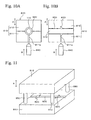
- Fig. 10 is a diagram showing the injection forming apparatus.
- Fig. 10(a) is a cross section of the injection forming apparatus in the perpendicular direction of the axial direction of the torsion part.
- Fig. 10(b) is a cross section of the injection forming apparatus in the axial direction of the torsion part.
- Fig. 11 is an oblique view showing the mold.
- Fig. 12 is a flow chart diagram showing a part of the process for production of the stabilizer device.
- the injection forming apparatus 800 in which the misalignment preventing member 400 is directly injected to the half-finished product of the stabilizer is explained by referring to the Figs. 10 and 11 .
- the injection forming apparatus 800 has the mold 810, the injecting machine 840, up-and-down mechanism 850 and so on.
- the mold 810 has the lower mold 811 and the upper mold 812.
- the gate 811 a is arranged at the lower mold 811.
- the concave part which is a part of the cavity 820 to form the misalignment preventing member 400 in a predetermined shape
- the grip part 830 which is continuously arranged at the cavity 820 and supports the shoulder part of the half-finished product of stabilizer, are arranged.
- the injecting machine 840 is an apparatus to fill resin into the cavity 820 of the mold.
- the up-and-down mechanism 850 is arranged at each of four corners of the mold 810.
- the up-and-down mechanism 850 lifts the upper mold 812 up and down in the direction A indicated by the arrows in Figs. 10 and 11 .
- the up-and-down mechanisms 850 are arranged at predetermined intervals so that the half-finished product of the stabilizer can go through between the up-and-down mechanisms 850 along the direction of which the grip part 830 is formed.
- the upper mold 812 goes upward by the up-and-down mechanism 850 along the direction A indicated by the arrow in Fig. 10 , the upper mold 812 is separated from the lower mold 811.
- the upper mold 812 goes downward by the up-and-down mechanism 850 along the direction A indicated by the arrow in Fig. 10 , the upper mold 812 comes into contact with the lower mold 811.
- the cavity 820 in which the misalignment preventing member 400 is formed into a predetermined shape is formed.
- a forming process in which bar material such as an electric resistance welded tube cut into predetermined length is formed so as to have a shape like that of a square bracket, a "]" shape, by a cold-working is performed (S801).
- a heat treatment process in which the half-finished product of the stabilizer is heat-treated by for example quenching or tempering is performed (S802).
- the shoulder part of the half-finished product of stabilizer is set into the grip part 830 of the mold 810.
- the up-and-down mechanism 850 the upper mold 812 is lifted downwardly along the direction A indicated by the arrow in Fig. 11 to contact with the lower mold 811, so as to form the cavity 820.
- the injecting machine 840 is moved in the direction B indicated by the arrow in Fig. 10 , the top of the injecting machine 840 is inserted into the gate 811a of the lower mold 811, and the resin is filled from the gate 811a into the cavity 830.
- the misalignment preventing member 400 consisting of the contacting part 410 and the tapered part 420 is formed on the half-finished product of the stabilizer.
- gap between the shoulder part of the half-finished product of the stabilizer and the grip part 830 is not more than 0.6 mm. Therefore, resin which is filled into the cavity 820 does not flow from the cavity 820 into the grip part 830, and therefore burrs are not formed.
- the misalignment preventing member 400 is about 10 mm long, the misalignment preventing member 400 can be formed even if the axial core of the misalignment preventing member 400 and the axial core of the shoulder part are relatively inclined about 3 to 4 degrees.
- the resin misalignment preventing member is about 10 mm long, diameter tolerance of the shoulder part and bent condition of the shoulder part of the inside of the misalignment preventing member 400 can be allowed to a greater degree. In addition, a process removing the burrs can be omitted. As a result, the stabilizer device 1 can be produced at low cost.
- the misalignment preventing member 400 is not fixed to the stabilizer 100 via coating (meaning fixed directly), fixing strength of the misalignment preventing member 400 is not affected by coating strength which is a degree of coating adhering to the half-product of the stabilizer.
- the misalignment preventing member may not move with the coating, fixing strength of the misalignment preventing member can be obtained, and reliability of the stabilizer device 1 can be increased.
- the number of the molds for forming the cavity 820 can be reduced to be from 1/3 to 1/4 compared to variation of molds for forming an aluminum ring, and therefore, a process for working out a plan or the like can be performed efficiently. As a result, production efficiency of the stabilizer device 1 can be increased.
- the present invention can be utilized for a stabilizer device equipped in an automobile body or the like.
Landscapes
- Engineering & Computer Science (AREA)
- Mechanical Engineering (AREA)
- General Engineering & Computer Science (AREA)
- Vehicle Body Suspensions (AREA)
- Springs (AREA)
- Injection Moulding Of Plastics Or The Like (AREA)
Abstract
Description
- The present invention relates to a stabilizer device, which may be mounted on an automobile or the like, and relates to a process for production thereof.
- A stabilizer in the stabilizer device functions as a spring, restraining horizontal oscillation of an automobile body by warping a left arm part and a right arm part in mutually opposing directions, and by contorting a torsion part, when mutually opposing phases in the up and down direction are applied to the suspension mechanisms on the left and right, when an automobile having such a stabilizer device passes through a curve. Conventionally, the stabilizer has been fixed to the automobile body by fastening a bracket to an automobile body side with a bolt via a rubber bush arranged on the stabilizer.
- However, due to a load generated by centrifugal force when passing through a curve, the torsion part and the bush may each resist the frictional force of the other, so that they become misaligned with each other. These misaligned parts will not be returned to their original positions even in the case in which a centrifugal force is generated in an opposite direction or in the case in which the automobile then goes straight, and thus the parts would be maintained misaligned from the original positions. Therefore, there may be a problem in which anti-roll effects by the stabilizer cannot be obtained, a problem in which excessive load may be applied on a stabilink fastened on both ends of the stabilizer, and there is a likely problem that the stabilizer may interfere at a circumferential part.
- To prevent the bush from being misaligned, an aluminum ring or an iron ring has been swaged as a misalignment preventing member. As the misalignment preventing member, one member for each of the left and right, in total two members, are used per one stabilizer. On the other hand, as a method for preventing the bush from being misaligned, there is a method in which a rubber bush itself is directly fixed to the torsion part by an adhesive or by a heat-curing process.
- In a process for production of a hollow stabilizer device having the aluminum ring as the misalignment preventing member, first, a forming process in which an electric resistance welded tube cut into a predetermined length is formed into a shape of a stabilizer by a cold-working is performed, next, a heat treatment process in which the half-finished product of the stabilizer is heat-treated by, for example, quenching or tempering is performed, next, shot-peening in which shot is impinged on the half-finished product of the stabilizer is performed, and next, a coating process in which the half-finished product of the stabilizer is coated is performed. After that, the aluminum ring consisting of half portions or two pieces is swaged to obtain the misalignment preventing member.
- In addition, in a process for production of a hollow stabilizer device having the iron ring as the misalignment preventing member, first, an arm part is formed by a bending process of an electric resistance welded tube cut into predetermined length, next, the electric resistance welded tube is bent and is inserted into an iron ring formed into a C-shape, and next, a process in which a flattened part and an attachment hole for attaching a stabilink are formed at an edge part of the arm part by forging or the like is performed. After that, the iron ring is swaged and a coating process is performed.
- On the other hand, in the process for fixing a rubber bush, the rubber bush is integrally formed at the torsion part of the stabilizer by direct injection, and it is then hardened by a heat curing process. As cited references concerning these techniques, Japanese Unexamined Patent Application Publication Nos.
2001-163026 2001-165127 - However, since it is a method for fixing in which an aluminum ring consisting of half portions or two pieces are swaged to the torsion part, the aluminum ring has a connecting part which is a structural weak point. Because of this connecting part, the strength of the aluminum ring is low. Therefore, in the case in which a load is applied to the aluminum ring, the swaged form may be easily broken. Therefore, the fixing strength of the aluminum ring may be easily deteriorated, and fixed positions of the stabilizer at left and right parts of the automobile may become unbalanced. When the automobile passes through a curve, the effects that the stabilizer originally had cannot be sufficiently obtained. As a result, it is not a stabilizer device having sufficient reliability.
- In addition, since the aluminum ring is swaged and fixed to the half finished product of the stabilizer after coating, the ring is fixed to the stabilizer via coating. Therefore, it may depend on the coating strength, which is a degree of adhering between the half-finished product of the stabilizer and the coating. Therefore, in the case in which the original coating strength is not obtained, the misalignment preventing member may move with the coating, the fixing strength of which the misalignment preventing member originally has cannot be obtained, and the function as the misalignment preventing member cannot be obtained. As a result, it is not a stabilizer device having sufficient reliability. Furthermore, in the case in which the misalignment preventing member is an aluminum ring or an iron ring, it is heavier than the misalignment preventing member made of resin. Therefore, weight reduction of the stabilizer device cannot be promoted.
- In addition, since deformation resistance of the iron ring is higher than that of the aluminum ring, the iron ring is formed into a circular shape so as to be swaged easily. Therefore, it is necessary that the torsion part be inserted into the ring before the flattened part and the attaching hole for attaching the stabilink are formed at the edge part of the arm part by forging or the like. That is, it is necessary that the electric resistance welded tube be inserted into the iron ring after bending the electric resistance welded tube and before coating of the half-finished product of the stabilizer. Therefore, handling is difficult since the process for forming the flattened part and attaching hole must be performed while the iron ring is maintained so as not to drop off or fall without swaging it.
- Furthermore, since the rubber bush requires the heat curing process, the process for production becomes complicated and is expensive. In addition, in the direct injection of rubber, part of the rubber forms burrs and projects from a gap between a shoulder part of a stabilizer and a grip part of a mold supporting the shoulder part of the stabilizer. For example, it has been demonstrated that the burrs are formed even in the case in which the gap is about 0.2 mm. Therefore, a process for removing the burrs is necessary, incurring additional costs.
- Therefore, an object of the present invention is to provide a stabilizer device having high reliability and which is light in weight.
- The stabilizer device of the present invention has a stabilizer consisting of a torsion part and arm parts each extending from both ends of the torsion part and forming an overall shape of a square bracket, a "]" shape, a bush for fixing the stabilizer to an automobile body arranged at both ends of the torsion part, and a resin misalignment preventing member which has a contacting part contacting with the bush, which is arranged neighboring with the bush, and which is integrally formed with the torsion part while covering all therearound in a predetermined range of an axial direction of the torsion part.
- As the resin, polyphenylene sulfide, polyetheretherketone or the like is desirable. For example, with a material such as polyphenylene sulfide or polyetheretherketone, if a condition of injection when the misalignment preventing member is directly injected is appropriately selected, generation of burrs can be prevented. Furthermore, a material such as polyphenylene sulfide or polyetheretherketone has enough heat resistance and strength to withstand heat in a coating process in which a coating of a stabilizer is dried that is performed after the injection forming process of the misalignment preventing member.
- By the present invention, since the misalignment preventing member does not have a connecting part which is a structural weak point, loss of fixing strength at the torsion part of the stabilizer by a load can be prevented, and the bush is maintained at an appropriate position of the torsion part. In addition, while the aluminum ring loses the ability to act as the misalignment preventing member immediately in the case in which load is applied on the aluminum ring, on the other hand, in the case in which the resin misalignment preventing member is misaligned, a load that is required to be misaligned is little changed. Therefore, the misalignment preventing member can maintain the function as the misalignment preventing member, of which the bush is prevented from moving along the axial direction of the torsion part. As a result, the stabilizer can exhibit the performance preliminarily designed, and the reliability can be increased. On the other hand, since the misalignment preventing member is made of resin, the weight is lighter than that of an aluminum ring or an iron ring. Therefore, weight reducing of the stabilizer device can be promoted.
- In the present invention, it is desirable that the misalignment preventing member have an inclining part on the contacting part at the opposite side of the bush, whose outer diameter is decreased as it is far from the bush along the axial direction of the torsion part. As such an inclining part, the inclining part can be of a tapered shape, and the cross section shape of the inclining part can be parabolic or circular.
- In the present invention, it is desirable that the misalignment preventing member have plural ribs on the contacting part at the opposite side of the bush, whose outer diameter is decreased as it is far from the bush along the axial direction of the torsion part. As such a rib, the inclining part can be a tapered shape, and the cross section shape of the inclining part can be parabolic or circular.
- According to the above aspect, in the case in which centrifugal force is generated at the automobile body, the load is applied on the bracket arranged on the outer circumference of the bush. If the load is applied like this, the bush is bent toward the misalignment preventing member. In this way, the load is applied to an outer circumferential part of a contacting part of the misalignment preventing member. Therefore, a moment acts in the misalignment preventing member toward the axial direction of the torsion part. That is, the inner circumferential surface of the misalignment preventing member presses the outer circumferential surface of the torsion part, and the load is applied from the misalignment preventing member to the torsion part. Therefore, frictional force between the torsion part and the misalignment preventing member is increased, and further higher frictional force is exhibited. As a result, the bush is prevented from being misaligned, and therefore reliability of the stabilizer device can be increased.
- Furthermore, by reducing excessive material, the misalignment preventing member can be prevented from interfering with surrounding parts of the member, and the cost and the weight can be reduced because of reducing resin used. In addition, during the coating process which is performed after the misalignment preventing member is formed, the risk of uneven coating around the misalignment preventing member, which occurs by the misalignment preventing member shielding the coating, can be reduced. Furthermore, in the case of ribs, compared to the case of the inclining part, the cost and the weight can be further reduced because of further reducing resin used.
- In the present invention, it is desirable that the misalignment preventing member be formed so as to be 10 mm to 15 mm long in the axial direction of the torsion part. In this aspect, while realizing the reduction in size of the misalignment preventing member, the frictional force which can bear against the load generated when contacting the bush and the misalignment preventing member by the centrifugal force generated when the automobile passes through a curve, can be exhibited. Therefore, the straight length of the torsion part (excluding the bush) of the stabilizer can be shortened as much as possible, and the stabilizer can be reduced in size. As a result, the weight of the stabilizer can be reduced.
- In the present invention, it is desirable that the misalignment preventing member be formed so as to be 3 mm to 5 mm thick at the thickest portion. In this aspect, while the misalignment preventing member can be reduced in size, an area in which the contacting part as the misalignment preventing member contacts the bush is maintained. Therefore, the misalignment preventing member can be prevented from interfering with surrounding parts of the member, and the weight of the stabilizer device can be reduced.
- In the present invention, it is desirable that convex and concave portions which prevent misalignment of the torsion part and the misalignment preventing member be arranged on an outer circumferential surface of the torsion part. As the concave and convex portions, methods for reducing roughness by shotblasting or shotpeening, forming dimples, forming projections, forming linear projections, or forming linear grooves may be mentioned. It should be noted that forming the concave and convex part by shotpeening is desirable since the number of processes is increased in the production of the stabilizer device if the dimples, projections, linear projections, and linear grooves are formed. In this aspect, because of the anchor effect, resistance to misalignment, which prevents the bush from misaligning, can be further increased. Therefore, the misalignment preventing member can further prevent the bush from moving along the axial direction of the torsion part. As a result, the reliability of the stabilizer can be increased.
- The process for production of the stabilizer device of the present invention has following processes, a forming process in which a bar material is formed into an overall shape of a square bracket, a "]" shape, a heat treatment process in which the half-finished product of the stabilizer is heated, a shot peening process in which shot is impinged on the half-finished product of the stabilizer, an injection forming process in which a misalignment preventing member is integrally formed at shoulder part of the half-finished product of the stabilizer with a resin by direct injection, and a coating process in which the half-finished product of the stabilizer and the misalignment preventing member are coated.
- By the present invention, since the misalignment preventing member does not have a connecting part which is a structural weak point, immediate loss of fixing strength at the torsion part of the stabilizer by load can be prevented, and the bush is maintained at an appropriate position of the torsion part. In addition, while the aluminum ring loses the ability as the misalignment preventing member immediately in the case in which load is applied on the aluminum ring, on the other hand, in the case in which the resin misalignment preventing member is misaligned, load required to be misaligned is little changed. Therefore, the misalignment preventing member can maintain the function as the misalignment preventing member, of which the bush is prevented from moving along the axial direction of the torsion part. As a result, the stabilizer can exhibit the performance preliminarily designed, and the reliability can be increased. On the other hand, since the misalignment preventing member is made of resin, the weight is lighter than that of an aluminum ring or an iron ring. Therefore, weight reduction of the stabilizer device can be promoted.
- Furthermore, since the coating process is performed after the misalignment preventing member is integrally formed, the misalignment preventing member is not fixed to the shoulder part via the coating (meaning fixed directly), the fixing strength of the misalignment preventing member is not affected by the coating strength which is a degree of coating adhering to the half-finished product of the stabilizer. Therefore, even in the case in which the original coating strength is not obtained, the misalignment preventing member does not move together with the coating, the fixing strength of the misalignment preventing member can be obtained, and the function as the misalignment preventing member can be exhibited sufficiently.
- In the present invention, it is desirable that a mold be used in the injection forming process, the mold has a cavity for forming the misalignment preventing member in predetermined shape and has a grip part being arranged so as to be continuous with the cavity and supporting the shoulder part of the half-finished product of the stabilizer, and in addition, a gap between the shoulder part and the grip part is not more than 0.6 mm during the direct injection. In this aspect, resin filled in the cavity does not flow from the cavity into the grip part, and burrs are not generated. Therefore, in the case of a resin misalignment preventing member having a length of 10 mm for example, diameter tolerance of the torsion part, bending of the torsion part inside of the misalignment preventing member, or the like, is widely allowed. In addition, a process for removing the burrs can be omitted. As a result, the stabilizer device can be produced at low cost.
- In the present invention, a stabilizer having high reliability and light weight can be produced.
-
-
Fig. 1 is a diagram showing the stabilizer device. -
Fig. 2 is a cross sectional view seen from line Z-Z inFig. 1 showing a condition being fixed to an automobile body. -
Fig. 3 is an oblique view showing the bracket. -
Fig. 4 is a cross sectional view showing a circumference of the misalignment preventing member being enlarged. -
Fig. 5 is an oblique view showing the misalignment preventing member. -
Fig. 6 is a diagram showing the embodiment in which the misalignment preventing member is arranged inside. -
Fig. 7 is a diagram showing a first variation of the misalignment preventing member. -
Fig. 8 is a diagram showing a second variation of the misalignment preventing member. -
Fig. 9 is a diagram showing a third variation of the misalignment preventing member. -
Fig. 10 is a diagram showing the injection forming apparatus. -
Fig. 11 is an oblique view showing the mold. -
Fig. 12 is a flow chart diagram showing a part of the process for production of the stabilizer device. - 1: Stabilizer device, 10: Automobile body, 100: Stabilizer, 110: Torsion part, 111: Convex and concave part, 300: Bush, 400: Misalignment preventing member, 410: Contacting part, 420: Tapered part, 520: Parabolic part, 620: Rib, 720: Rib, 810: Mold, 820: Cavity, 830: Grip part.
- Hereinafter, an embodiment of the invention will be explained by referring to the drawings.
Fig. 1 is a diagram showing the stabilizer device.Fig. 2 is a cross sectional view seen from line Z-Z inFig. 1 showing a condition being fixed to an automobile body.Fig. 3 is an oblique view showing the bracket.Fig. 4 is a cross sectional view showing a circumference of the misalignment preventing member enlarged.Fig. 4A is a diagram showing a condition in which centrifugal force is not generated.Fig. 4B is a diagram showing a condition in which centrifugal force is generated.Fig. 5 is an oblique view showing the misalignment preventing member.Fig. 6 is a diagram showing the embodiment in which the misalignment preventing member is arranged inside.Fig. 7 is a diagram showing a first variation of the misalignment preventing member.Fig. 8 is a diagram showing a second variation of the misalignment preventing member.Fig. 9 is a diagram showing a third variation of the misalignment preventing member. - As shown in
Fig. 1 , thestabilizer device 1 has thestabilizer 100,bushes 300, and themisalignment preventing members 400 or the like. Thestabilizer 100 has thetorsion part 110, and thearm parts 120. In thestabilizer 100, thetorsion part 110 and thearm parts 120 are formed by processing a bar material such as a hollow pipe such as an electric resistance welded tube or solid pipe. At both end parts of thetorsion part 110, a pair of left arm andright arm 120, each extending from both end parts are arranged. At the top part of thearm part 120, the flattenedpart 121 which is flattened by forging is formed. At the flattenedpart 121, the attachinghole 122 for attaching a stabilizer link, not shown, by insertion is formed. - The
stabilizer 100 in thestabilizer device 1 functions as a spring restraining horizontal oscillation of anautomobile body 10 by deforming a left arm part and aright arm part 120 in opposite directions and by deforming thetorsion part 110, when opposing phases in the up and down direction are applied in suspension mechanisms of the left and right (not shown), when an automobile havingsuch stabilizer device 1 passes through a curve. - The
torsion part 110 is linear and is formed in a solid or hollow cylindrical shape. On the outer circumferential surface of thetorsion part 110, concave andconvex part 111 formed by shotpeening is formed. On thetorsion part 110, thebush 300 for attaching thestabilizer device 1 onto theautomobile body 10 is provided. Furthermore, on thetorsion part 110, themisalignment preventing member 400 preventing thebush 300 from being misaligned is provided. - As shown in
Fig. 1 , thebush 300 is attached to each of left and right of thetorsion part 110. Thebush 300 is made of rubber, and is formed bigger than themisalignment preventing member 400. As shown inFigs. 2 and4 , thebush 300 is a member to fix thestabilizer 100 to theautomobile body 10, by tightening the letterU shape bracket 20 which is surrounding outer circumference of thebush 300 shown inFig. 3 by a bolt to theautomobile body 10 side. - The
misalignment preventing member 400 is made of resin. As the resin forming themisalignment preventing member 400, polyphenylenesulfide or polyetheretherketone or the like may be mentioned. Themisalignment preventing member 400 is integrally formed with thetorsion part 110 while covering all therearound in a predetermined range of axial direction of thetorsion part 110. - Since the
misalignment preventing member 400 is integrally formed in this way, themisalignment preventing member 400 does not have a connecting part which is a structural weak point, easy loss of fixing strength at thetorsion part 110 of thestabilizer 100 by load can be prevented, and thebush 300 is maintained at an appropriate position of thetorsion part 110. In addition, while the aluminum ring loses the ability as the misalignment preventing member immediately in the case in which load is applied on the aluminum ring, on the other hand, in the case in which the resinmisalignment preventing member 400 is misaligned, load required to be misaligned is little changed. Therefore, themisalignment preventing member 400 can maintain the function as the misalignment preventing member, of which thebush 300 is prevented from moving along the axial direction of thetorsion part 110. As a result, thestabilizer 100 can exhibit the performance preliminarily designed, and the reliability can be increased. - As shown in
Fig. 1 , themisalignment preventing member 400 is arranged neighboring to the outside of thebush 300. That is, themisalignment preventing member 400 is arranged at each of the left and right of thetorsion part 110, and in total, two members are arranged. Themisalignment preventing member 400 has the contactingpart 410 and the incliningpart 420. Themisalignment preventing part 400 prevents thebush 300 from moving along the axial direction of thetorsion part 110. - It should be noted that the present invention is not limited in the embodiment in which each
misalignment member 400 is arranged neighboring to the outside of thebush 300. As shown inFig. 6 , even in the case in which eachmisalignment member 400 is arranged neighboring to the inside of thebush 300, the function as the misalignment preventing member can be exhibited. - The
misalignment preventing member 400 is formed so as to be 10 mm to 15 mm long. Therefore, while themisalignment preventing member 400 is reduced in size, resistance to misalignment which prevents thebush 300 from being misaligned by the centrifugal force generated when the automobile passes through a curve can be exhibited. Therefore, in thestabilizer 100, straight length of thetorsion part 110 excluding thebush 300 can be shortened as much as possible, and thestabilizer 100 can be reduced in size. As a result, weight of thestabilizer device 1 can be reduced. It should be noted that the length of themisalignment member 400 is determined according to the resistance to misalignment required to prevent thebush 300 from being misaligned by the centrifugal force generated when the automobile passes through a curve. - Furthermore, in the present embodiment, since the convex and
concave part 111 is existing at the contacting part of thetorsion part 110 and themisalignment preventing member 400, since resistance to misalignment is large even in the case in which themisalignment preventing member 400 is short, length of themisalignment preventing member 400 can be further shortened. - As shown in
Fig. 5 or the like, the contactingpart 410 is formed to have a flanged shape. The side surface of thebush 300 contacts the side surface of the contactingpart 410. The contactingpart 410 is a part at which the thickness is greatest in themisalignment preventing member 400, and is formed to have a thickness of 3 mm to 5 mm. Therefore, while themisalignment preventing member 400 can be reduced in size, an area in which the contactingpart 410 as themisalignment preventing member 400 contacts thebush 300 can be maintained, and themisalignment preventing member 400 can be prevented from interfering with the surrounding parts of themisalignment preventing member 400. As a result, the weight of thestabilizer device 1 can be reduced. - As shown in
Fig. 5 or the like, thetapered part 420 is formed to having a tapered shape. That is, thetapered part 420 is formed on the contactingpart 410 at the opposite side of thebush 300 so that the outer diameter is decreased as it is far from thebush 300 along axial direction of thetorsion part 110. - It should be noted that the present invention is not limited to the embodiment in which the
tapered part 420 is arranged. As shown inFig. 7 , by forming so that the cross section of the inclining part is parabolic, theparabolic part 520 in which constituent material is reduced compared to thetapered part 420 can be formed. Alternatively, the tapered shapedrib 620 in which constituent material is further reduced compared to thetapered part 420 and theparabolic part 520 as shown inFig. 8 can be formed, or therib 720 in which the cross section of the inclining part is parabolic as shown inFig. 9 can be formed. - By reducing the constituent material as much as possible in this way, the misalignment preventing member can be prevented from interfering with the surrounding part of the misalignment preventing member, and the cost and the weight can be reduced because of reducing the resin used. Furthermore, during the coating process which is performed after the misalignment preventing member is formed, the risk of uneven coating around the misalignment preventing member, which occurs by the misalignment preventing member shielding the coating, can be reduced.
- Regarding weight reduction of the misalignment preventing member, in the case of the misalignment preventing member of an aluminum ring for example, in the case in which a misalignment preventing member which is arranged at a stabilizer having a diameter of 25.4 mm is designed, it would have a cylindrical shape with a thickness of 5.0 mm, a length of 15.0 mm, and a weight of 16 g. On the other hand, in the case in which the
misalignment preventing member 700 made of resin shown inFig. 9 which is arranged at a stabilizer having a diameter of 25.4 mm is designed, it would have a weight of 5 g, and thus, about 11 g per part of weight reduction can be obtained. Therefore, since the two misalignment preventing members are arranged on one stabilizer, total weight reduction of 22 g can be obtained. - Hereinafter, the fact that the
misalignment preventing member 400 can exhibit higher frictional force than a conventional misalignment preventing member such as an aluminum ring or an iron ring is explained by referring toFig. 4 . - In the case in which centrifugal force is generated on the
automobile body 10 in the X direction indicated by the arrow, load is applied on thebracket 20 arranged at the outer circumference of thebush 300. When the load is applied in this way, as shown inFig. 4(b) , thebush 300 is deformed to themisalignment preventing member 400 side. In this way, load is applied at the outer circumferential part of the contactingpart 410 of themisalignment preventing member 400. Therefore, a moment is applied to themisalignment preventing member 400 toward the axial direction of the torsion part 110 (Y direction indicated by the arrow inFig. 4 ). That is, the inner circumferential surface of themisalignment preventing member 400 presses the outer circumferential surface of thetorsion part 110, and load is applied from themisalignment preventing member 400 to thetorsion part 110. Therefore, frictional force between thetorsion part 110 and themisalignment preventing member 400 is increased, and higher frictional force can be exhibited. As a result, thebush 300 is prevented from being misaligned, and reliability of thestabilizer device 1 can be increased. Furthermore, since the convex andconcave part 111 is formed, high resistance to misalignment can be exhibited. - Next, part of the process for production of the
stabilizer device 1 is explained by referring to the figures. From the forming process to the coating process is explained.Fig. 10 is a diagram showing the injection forming apparatus.Fig. 10(a) is a cross section of the injection forming apparatus in the perpendicular direction of the axial direction of the torsion part.Fig. 10(b) is a cross section of the injection forming apparatus in the axial direction of the torsion part.Fig. 11 is an oblique view showing the mold.Fig. 12 is a flow chart diagram showing a part of the process for production of the stabilizer device. - Hereinafter, the
injection forming apparatus 800 in which themisalignment preventing member 400 is directly injected to the half-finished product of the stabilizer is explained by referring to theFigs. 10 and 11 . As shown inFig. 10 , theinjection forming apparatus 800 has themold 810, the injectingmachine 840, up-and-down mechanism 850 and so on. Themold 810 has thelower mold 811 and theupper mold 812. Thegate 811 a is arranged at thelower mold 811. On thelower mold 811 and theupper mold 812, the concave part which is a part of thecavity 820 to form themisalignment preventing member 400 in a predetermined shape, and thegrip part 830 which is continuously arranged at thecavity 820 and supports the shoulder part of the half-finished product of stabilizer, are arranged. - The injecting
machine 840 is an apparatus to fill resin into thecavity 820 of the mold. The up-and-down mechanism 850 is arranged at each of four corners of themold 810. The up-and-down mechanism 850 lifts theupper mold 812 up and down in the direction A indicated by the arrows inFigs. 10 and 11 . The up-and-downmechanisms 850 are arranged at predetermined intervals so that the half-finished product of the stabilizer can go through between the up-and-downmechanisms 850 along the direction of which thegrip part 830 is formed. - When the
upper mold 812 goes upward by the up-and-down mechanism 850 along the direction A indicated by the arrow inFig. 10 , theupper mold 812 is separated from thelower mold 811. On the other hand, when theupper mold 812 goes downward by the up-and-down mechanism 850 along the direction A indicated by the arrow inFig. 10 , theupper mold 812 comes into contact with thelower mold 811. When thelower mold 811 and theupper mold 812 are in contact, thecavity 820 in which themisalignment preventing member 400 is formed into a predetermined shape is formed. - A part of the process for production of the
stabilizer device 1 is explained by referring to theFig. 12 . First, a forming process in which bar material such as an electric resistance welded tube cut into predetermined length is formed so as to have a shape like that of a square bracket, a "]" shape, by a cold-working is performed (S801). Next, a heat treatment process in which the half-finished product of the stabilizer is heat-treated by for example quenching or tempering is performed (S802). Next, shot-peening in which shot is impinged on the half-finished product of the stabilizer is performed, burrs or the like on the surface of thetorsion part 110 are removed, while the convex andconcave part 111 is formed on thetorsion part 110 of the half-finished product of stabilizer (S803). - Next, using the
injection forming apparatus 800, an injection forming process in which themisalignment preventing member 400 is integrally formed on the half-finished product of stabilizer processed as mentioned above with resin by direct injection, is performed (S804). - During the injection forming process, first, the shoulder part of the half-finished product of stabilizer is set into the
grip part 830 of themold 810. Next, by the up-and-down mechanism 850, theupper mold 812 is lifted downwardly along the direction A indicated by the arrow inFig. 11 to contact with thelower mold 811, so as to form thecavity 820. Next, the injectingmachine 840 is moved in the direction B indicated by the arrow inFig. 10 , the top of the injectingmachine 840 is inserted into thegate 811a of thelower mold 811, and the resin is filled from thegate 811a into thecavity 830. In this way, themisalignment preventing member 400 consisting of the contactingpart 410 and thetapered part 420 is formed on the half-finished product of the stabilizer. - At this time, gap between the shoulder part of the half-finished product of the stabilizer and the
grip part 830 is not more than 0.6 mm. Therefore, resin which is filled into thecavity 820 does not flow from thecavity 820 into thegrip part 830, and therefore burrs are not formed. For example, in the case in which themisalignment preventing member 400 is about 10 mm long, themisalignment preventing member 400 can be formed even if the axial core of themisalignment preventing member 400 and the axial core of the shoulder part are relatively inclined about 3 to 4 degrees. Therefore, in the case in which the resin misalignment preventing member is about 10 mm long, diameter tolerance of the shoulder part and bent condition of the shoulder part of the inside of themisalignment preventing member 400 can be allowed to a greater degree. In addition, a process removing the burrs can be omitted. As a result, thestabilizer device 1 can be produced at low cost. - After that, coating process in which the half-finished product of the stabilizer and the
misalignment preventing member 400 are coated is performed (S805). Therefore, themisalignment preventing member 400 is not fixed to thestabilizer 100 via coating (meaning fixed directly), fixing strength of themisalignment preventing member 400 is not affected by coating strength which is a degree of coating adhering to the half-product of the stabilizer. As a result, in the case in which original coating strength is not obtained, the misalignment preventing member may not move with the coating, fixing strength of the misalignment preventing member can be obtained, and reliability of thestabilizer device 1 can be increased. - In the case in which the mold is constructed so that the mold can be divided into a mold part for forming the
cavity 820 and a mold part for forming thegrip part 830, the number of the molds for forming thecavity 820 can be reduced to be from 1/3 to 1/4 compared to variation of molds for forming an aluminum ring, and therefore, a process for working out a plan or the like can be performed efficiently. As a result, production efficiency of thestabilizer device 1 can be increased. - As explained above, the present invention can be utilized for a stabilizer device equipped in an automobile body or the like.
Claims (8)
- A stabilizer device comprising:a stabilizer consisting of a torsion part and arm parts each extending from both ends of the torsion part and forming an overall shape of a square bracket, a "]" shape,a bush for fixing the stabilizer to an automobile body arranged at both ends of the torsion part,a misalignment preventing member made of resin which has a contacting part contacting with the bush, which is arranged neighboring with the bush, and which is integrally formed with the torsion part and covers all around in a predetermined range of an axial direction of the torsion part.
- The stabilizer device according to claim 1, wherein the misalignment preventing member has an inclining part on the contacting part at the opposite side of the bush, whose outer diameter is decreased as it is far from the bush along an axial direction of the torsion part.
- The stabilizer device according to claim 1, wherein the misalignment preventing member has plural ribs on the contacting part at the opposite side of the bush, whose outer diameter is decreased as it is far from the bush along an axial direction of the torsion part.
- The stabilizer device according to claim 1, wherein the misalignment preventing member is formed so as to be 10 to 15 mm long in the axial direction of the torsion part.
- The stabilizer device according to claim 1, wherein the misalignment preventing member is formed so as to be 3 to 5 mm thick at the thickest portion.
- The stabilizer device according to claim 1, wherein convex and concave portions which prevent misalignment of the torsion part and the misalignment preventing member are arranged at an outer circumferential surface of the torsion part.
- A process for production of the stabilizer device, the process comprising:a forming process in which a bar material having the form of a square bracket, a "]" form,a heat treatment process in which the half-finished product of the stabilizer is heated,a shot peening process in which shot is impinged on the half-finished product of the stabilizer,an injection forming process in which a misalignment preventing member is integrally formed at a shoulder part of the half-finished product of the stabilizer with resin by direct injection, anda coating process in which the half-finished product of the stabilizer and the misalignment preventing member are coated.
- The process for production of the stabilizer device according to claim 7,
wherein a mold is used in the injection forming process, the mold having a cavity for forming the misalignment preventing member in a predetermined shape and having a grip part being arranged so as to be continuous with the cavity and supporting the shoulder part of the half-finished product of the stabilizer, and
wherein a gap between the shoulder part and the grip part is not more than 0.6 mm during the direct injection.
Applications Claiming Priority (2)
| Application Number | Priority Date | Filing Date | Title |
|---|---|---|---|
| JP2008104567A JP4663752B2 (en) | 2008-04-14 | 2008-04-14 | Stabilizer device and manufacturing method thereof |
| PCT/JP2009/057445 WO2009128423A1 (en) | 2008-04-14 | 2009-04-13 | Stabilizer device and method for manufacturing the same |
Publications (3)
| Publication Number | Publication Date |
|---|---|
| EP2277727A1 true EP2277727A1 (en) | 2011-01-26 |
| EP2277727A4 EP2277727A4 (en) | 2011-12-07 |
| EP2277727B1 EP2277727B1 (en) | 2013-06-19 |
Family
ID=41199114
Family Applications (1)
| Application Number | Title | Priority Date | Filing Date |
|---|---|---|---|
| EP09733408.0A Not-in-force EP2277727B1 (en) | 2008-04-14 | 2009-04-13 | Stabilizer device and method for manufacturing the same |
Country Status (8)
| Country | Link |
|---|---|
| US (1) | US8356825B2 (en) |
| EP (1) | EP2277727B1 (en) |
| JP (1) | JP4663752B2 (en) |
| KR (1) | KR20110003364A (en) |
| CN (1) | CN102066140B (en) |
| BR (1) | BRPI0910939A2 (en) |
| ES (1) | ES2425495T3 (en) |
| WO (1) | WO2009128423A1 (en) |
Families Citing this family (12)
| Publication number | Priority date | Publication date | Assignee | Title |
|---|---|---|---|---|
| JP4890371B2 (en) * | 2007-07-12 | 2012-03-07 | 本田技研工業株式会社 | Stabilizer support structure |
| EP2357099B1 (en) * | 2010-02-16 | 2017-07-12 | Benteler Automobiltechnik GmbH | Stabiliser and method for manufacturing a stabiliser |
| US20120211958A1 (en) * | 2011-02-22 | 2012-08-23 | H & L Tool and Die Ltd. | Method and apparatus for producing a stabilizer bar assembly |
| US8777245B2 (en) * | 2012-11-16 | 2014-07-15 | The Pullman Company | Optimized wall thickness torque rod |
| DE102013218413A1 (en) * | 2013-09-13 | 2015-03-19 | Zf Friedrichshafen Ag | Stabilizer of a motor vehicle and method for producing the same |
| CN103658480B (en) * | 2013-12-03 | 2015-09-02 | 安庆市恒瑞达汽车零部件制造有限公司 | The resiliency supported of a kind of automobile stabilizer bar termination forging equipment |
| CN105522884B (en) * | 2014-09-30 | 2018-05-29 | 比亚迪股份有限公司 | The chassis of car |
| EP3357724B1 (en) * | 2015-10-02 | 2020-08-26 | NHK Spring Co., Ltd. | Stabilizer for vehicle |
| EP3653414B1 (en) * | 2017-07-14 | 2023-06-28 | NHK Spring Co., Ltd. | Vehicle stabilizer, and shot peening jig with stabilizers |
| CN111002779B (en) * | 2019-12-19 | 2021-06-08 | 北京汽车集团越野车有限公司 | Stabilizer bar installation clip |
| US11713570B1 (en) * | 2021-09-16 | 2023-08-01 | Ileana Rodriguez | Member to structural member connector |
| CN116518152A (en) * | 2023-06-09 | 2023-08-01 | 腾达建设集团股份有限公司 | Dislocation fixing device for pipe joints and method for fixing dislocation pipe joints using it |
Family Cites Families (27)
| Publication number | Priority date | Publication date | Assignee | Title |
|---|---|---|---|---|
| DE3921457A1 (en) * | 1989-06-30 | 1991-01-10 | Hoesch Ag | TORSION BAR |
| IT1285856B1 (en) * | 1996-05-03 | 1998-06-24 | Rejna Spa | POSITIONING DEVICE FOR STABILIZER BARS, STABILIZER BAR AND STABILIZATION SYSTEM FOR USING VEHICLES |
| DE19738769A1 (en) * | 1997-09-04 | 1999-03-11 | Bayerische Motoren Werke Ag | Storage of a stabilizer on a motor vehicle |
| JP3963593B2 (en) | 1998-04-23 | 2007-08-22 | 横浜機工株式会社 | Bar material slip prevention structure |
| JP3963592B2 (en) * | 1998-09-21 | 2007-08-22 | 横浜機工株式会社 | Bar material slip prevention structure |
| JP2000079819A (en) * | 1998-07-01 | 2000-03-21 | Mitsubishi Steel Mfg Co Ltd | Stabilizer side slip prevention device |
| JP2002331326A (en) * | 2001-03-08 | 2002-11-19 | Nhk Spring Co Ltd | Hollow stabilizer and method of manufacturing the same |
| US6889988B2 (en) * | 2002-04-17 | 2005-05-10 | Visteon Global Technologies, Inc. | Variable rate gripped bushing system |
| US6845995B2 (en) * | 2002-11-08 | 2005-01-25 | Visteon Global Technologies, Inc. | Method of forming compression gripped bushing system |
| US6971640B2 (en) * | 2003-04-18 | 2005-12-06 | Research And Manufacturing Corporation Of America | Sway bar bushing |
| US7621513B2 (en) * | 2003-10-08 | 2009-11-24 | ArvinMeritor Light Vehicle Systems (UK) Lt.d | Stabilizer bar lateral retainer collar |
| US7065875B2 (en) * | 2003-11-25 | 2006-06-27 | Automotive Components Holdings, Llc | Bushing support ring for stabilizer bar |
| US7128328B2 (en) * | 2004-02-18 | 2006-10-31 | Automotive Components Holdings, Llc | Mechanical stop for a rigid bar |
| US20050214560A1 (en) * | 2004-03-25 | 2005-09-29 | Stephen Yue | Thermal spray reinforcement of a stabilizer bar |
| JP4323358B2 (en) * | 2004-03-26 | 2009-09-02 | 三菱製鋼株式会社 | Stabilizer anti-slip device |
| US7318593B2 (en) * | 2004-10-15 | 2008-01-15 | Ford Global Technologies, Llc | Stabilizer bar and bushing assembly |
| JP4560376B2 (en) * | 2004-10-29 | 2010-10-13 | 東海ゴム工業株式会社 | Stabilizer bush |
| JP4633575B2 (en) | 2005-08-18 | 2011-02-16 | トヨタ自動車株式会社 | Stabilizer bush |
| US7448636B2 (en) * | 2005-10-14 | 2008-11-11 | American Axle & Manufacturing, Inc. | Stabilizer bar |
| DE102006002749A1 (en) * | 2006-01-20 | 2007-09-20 | Dr.Ing.H.C. F. Porsche Ag | bearing element |
| US20080036166A1 (en) * | 2006-08-14 | 2008-02-14 | Meritor Suspension Suystems Company, Us | Self-locking sleeve for stabilizer bar |
| US20080093817A1 (en) * | 2006-10-23 | 2008-04-24 | Meritor Suspension Systems Company, U.S. | Crimp ring and stabilizer bar assembly |
| US20080111335A1 (en) * | 2006-11-13 | 2008-05-15 | Thyssenkrupp Bilstein Of America | Stabilizer bar with a lateral retention collar and method of manufacture |
| JP2009196505A (en) * | 2008-02-21 | 2009-09-03 | Nhk Spring Co Ltd | Vehicle stabilizer |
| JP5748318B2 (en) * | 2008-07-18 | 2015-07-15 | 日本発條株式会社 | Stabilizer device |
| JP5398192B2 (en) * | 2008-07-29 | 2014-01-29 | 日本発條株式会社 | Stabilizer device and manufacturing method thereof |
| DE102009005898A1 (en) * | 2009-01-23 | 2010-07-29 | Audi Ag | Arrangement of a stabilizer on a suspension for motor vehicles |
-
2008
- 2008-04-14 JP JP2008104567A patent/JP4663752B2/en not_active Expired - Fee Related
-
2009
- 2009-04-13 KR KR1020107025242A patent/KR20110003364A/en not_active Ceased
- 2009-04-13 ES ES09733408T patent/ES2425495T3/en active Active
- 2009-04-13 CN CN2009801224312A patent/CN102066140B/en not_active Expired - Fee Related
- 2009-04-13 US US12/936,013 patent/US8356825B2/en active Active
- 2009-04-13 WO PCT/JP2009/057445 patent/WO2009128423A1/en not_active Ceased
- 2009-04-13 EP EP09733408.0A patent/EP2277727B1/en not_active Not-in-force
- 2009-04-13 BR BRPI0910939A patent/BRPI0910939A2/en not_active IP Right Cessation
Also Published As
| Publication number | Publication date |
|---|---|
| EP2277727B1 (en) | 2013-06-19 |
| JP2009255634A (en) | 2009-11-05 |
| JP4663752B2 (en) | 2011-04-06 |
| US8356825B2 (en) | 2013-01-22 |
| US20110025013A1 (en) | 2011-02-03 |
| CN102066140A (en) | 2011-05-18 |
| BRPI0910939A2 (en) | 2018-01-09 |
| CN102066140B (en) | 2013-09-11 |
| ES2425495T3 (en) | 2013-10-15 |
| EP2277727A4 (en) | 2011-12-07 |
| WO2009128423A1 (en) | 2009-10-22 |
| KR20110003364A (en) | 2011-01-11 |
Similar Documents
| Publication | Publication Date | Title |
|---|---|---|
| EP2277727B1 (en) | Stabilizer device and method for manufacturing the same | |
| CN102099210B (en) | Stabilizer device | |
| CN102112330A (en) | Stabilizer device and method of manufacturing same | |
| JP2011002095A (en) | Coil spring | |
| EP1853438B1 (en) | Raised-center axle and process for forming | |
| KR100734130B1 (en) | Tapered stabilizer bar with sequential release cross section and its manufacturing method | |
| KR102300263B1 (en) | Suspension bush assembly for vehicle | |
| KR102625468B1 (en) | Coupling rod, wheel suspension and method for producing a coupling rod | |
| JP6258243B2 (en) | Stabilizer and manufacturing method thereof | |
| JP3909531B2 (en) | Automotive stabilizer | |
| US20080093817A1 (en) | Crimp ring and stabilizer bar assembly | |
| US7128328B2 (en) | Mechanical stop for a rigid bar | |
| CN112566803B (en) | Stabilizer and manufacturing method thereof | |
| KR20140068816A (en) | Part for Automotive Vehicle | |
| JP7266716B2 (en) | Hollow spring manufacturing method | |
| CN107735305B (en) | Transport protection of steering columns of motor vehicles | |
| JPS6177508A (en) | Radius rod for car | |
| KR20080042410A (en) | Cylinder tube assembly for steering system and manufacturing method suitable for it |
Legal Events
| Date | Code | Title | Description |
|---|---|---|---|
| PUAI | Public reference made under article 153(3) epc to a published international application that has entered the european phase |
Free format text: ORIGINAL CODE: 0009012 |
|
| 17P | Request for examination filed |
Effective date: 20101115 |
|
| AK | Designated contracting states |
Kind code of ref document: A1 Designated state(s): AT BE BG CH CY CZ DE DK EE ES FI FR GB GR HR HU IE IS IT LI LT LU LV MC MK MT NL NO PL PT RO SE SI SK TR |
|
| AX | Request for extension of the european patent |
Extension state: AL BA RS |
|
| DAX | Request for extension of the european patent (deleted) | ||
| A4 | Supplementary search report drawn up and despatched |
Effective date: 20111104 |
|
| RIC1 | Information provided on ipc code assigned before grant |
Ipc: F16F 1/16 20060101ALI20111028BHEP Ipc: B60G 21/055 20060101AFI20111028BHEP |
|
| GRAP | Despatch of communication of intention to grant a patent |
Free format text: ORIGINAL CODE: EPIDOSNIGR1 |
|
| GRAS | Grant fee paid |
Free format text: ORIGINAL CODE: EPIDOSNIGR3 |
|
| GRAA | (expected) grant |
Free format text: ORIGINAL CODE: 0009210 |
|
| AK | Designated contracting states |
Kind code of ref document: B1 Designated state(s): AT BE BG CH CY CZ DE DK EE ES FI FR GB GR HR HU IE IS IT LI LT LU LV MC MK MT NL NO PL PT RO SE SI SK TR |
|
| REG | Reference to a national code |
Ref country code: GB Ref legal event code: FG4D |
|
| REG | Reference to a national code |
Ref country code: CH Ref legal event code: EP |
|
| REG | Reference to a national code |
Ref country code: AT Ref legal event code: REF Ref document number: 617441 Country of ref document: AT Kind code of ref document: T Effective date: 20130715 |
|
| REG | Reference to a national code |
Ref country code: IE Ref legal event code: FG4D |
|
| REG | Reference to a national code |
Ref country code: DE Ref legal event code: R096 Ref document number: 602009016537 Country of ref document: DE Effective date: 20130814 |
|
| REG | Reference to a national code |
Ref country code: ES Ref legal event code: FG2A Ref document number: 2425495 Country of ref document: ES Kind code of ref document: T3 Effective date: 20131015 |
|
| PG25 | Lapsed in a contracting state [announced via postgrant information from national office to epo] |
Ref country code: SI Free format text: LAPSE BECAUSE OF FAILURE TO SUBMIT A TRANSLATION OF THE DESCRIPTION OR TO PAY THE FEE WITHIN THE PRESCRIBED TIME-LIMIT Effective date: 20130619 Ref country code: NO Free format text: LAPSE BECAUSE OF FAILURE TO SUBMIT A TRANSLATION OF THE DESCRIPTION OR TO PAY THE FEE WITHIN THE PRESCRIBED TIME-LIMIT Effective date: 20130919 Ref country code: LT Free format text: LAPSE BECAUSE OF FAILURE TO SUBMIT A TRANSLATION OF THE DESCRIPTION OR TO PAY THE FEE WITHIN THE PRESCRIBED TIME-LIMIT Effective date: 20130619 Ref country code: SE Free format text: LAPSE BECAUSE OF FAILURE TO SUBMIT A TRANSLATION OF THE DESCRIPTION OR TO PAY THE FEE WITHIN THE PRESCRIBED TIME-LIMIT Effective date: 20130619 Ref country code: FI Free format text: LAPSE BECAUSE OF FAILURE TO SUBMIT A TRANSLATION OF THE DESCRIPTION OR TO PAY THE FEE WITHIN THE PRESCRIBED TIME-LIMIT Effective date: 20130619 Ref country code: GR Free format text: LAPSE BECAUSE OF FAILURE TO SUBMIT A TRANSLATION OF THE DESCRIPTION OR TO PAY THE FEE WITHIN THE PRESCRIBED TIME-LIMIT Effective date: 20130920 |
|
| REG | Reference to a national code |
Ref country code: AT Ref legal event code: MK05 Ref document number: 617441 Country of ref document: AT Kind code of ref document: T Effective date: 20130619 |
|
| REG | Reference to a national code |
Ref country code: LT Ref legal event code: MG4D |
|
| PG25 | Lapsed in a contracting state [announced via postgrant information from national office to epo] |
Ref country code: HR Free format text: LAPSE BECAUSE OF FAILURE TO SUBMIT A TRANSLATION OF THE DESCRIPTION OR TO PAY THE FEE WITHIN THE PRESCRIBED TIME-LIMIT Effective date: 20130619 Ref country code: BG Free format text: LAPSE BECAUSE OF FAILURE TO SUBMIT A TRANSLATION OF THE DESCRIPTION OR TO PAY THE FEE WITHIN THE PRESCRIBED TIME-LIMIT Effective date: 20130919 |
|
| REG | Reference to a national code |
Ref country code: NL Ref legal event code: VDEP Effective date: 20130619 |
|
| PG25 | Lapsed in a contracting state [announced via postgrant information from national office to epo] |
Ref country code: LV Free format text: LAPSE BECAUSE OF FAILURE TO SUBMIT A TRANSLATION OF THE DESCRIPTION OR TO PAY THE FEE WITHIN THE PRESCRIBED TIME-LIMIT Effective date: 20130619 |
|
| PG25 | Lapsed in a contracting state [announced via postgrant information from national office to epo] |
Ref country code: PT Free format text: LAPSE BECAUSE OF FAILURE TO SUBMIT A TRANSLATION OF THE DESCRIPTION OR TO PAY THE FEE WITHIN THE PRESCRIBED TIME-LIMIT Effective date: 20131021 Ref country code: AT Free format text: LAPSE BECAUSE OF FAILURE TO SUBMIT A TRANSLATION OF THE DESCRIPTION OR TO PAY THE FEE WITHIN THE PRESCRIBED TIME-LIMIT Effective date: 20130619 Ref country code: CY Free format text: LAPSE BECAUSE OF FAILURE TO SUBMIT A TRANSLATION OF THE DESCRIPTION OR TO PAY THE FEE WITHIN THE PRESCRIBED TIME-LIMIT Effective date: 20130918 Ref country code: IS Free format text: LAPSE BECAUSE OF FAILURE TO SUBMIT A TRANSLATION OF THE DESCRIPTION OR TO PAY THE FEE WITHIN THE PRESCRIBED TIME-LIMIT Effective date: 20131019 Ref country code: BE Free format text: LAPSE BECAUSE OF FAILURE TO SUBMIT A TRANSLATION OF THE DESCRIPTION OR TO PAY THE FEE WITHIN THE PRESCRIBED TIME-LIMIT Effective date: 20130619 Ref country code: CZ Free format text: LAPSE BECAUSE OF FAILURE TO SUBMIT A TRANSLATION OF THE DESCRIPTION OR TO PAY THE FEE WITHIN THE PRESCRIBED TIME-LIMIT Effective date: 20130619 Ref country code: SK Free format text: LAPSE BECAUSE OF FAILURE TO SUBMIT A TRANSLATION OF THE DESCRIPTION OR TO PAY THE FEE WITHIN THE PRESCRIBED TIME-LIMIT Effective date: 20130619 Ref country code: EE Free format text: LAPSE BECAUSE OF FAILURE TO SUBMIT A TRANSLATION OF THE DESCRIPTION OR TO PAY THE FEE WITHIN THE PRESCRIBED TIME-LIMIT Effective date: 20130619 |
|
| PG25 | Lapsed in a contracting state [announced via postgrant information from national office to epo] |
Ref country code: RO Free format text: LAPSE BECAUSE OF FAILURE TO SUBMIT A TRANSLATION OF THE DESCRIPTION OR TO PAY THE FEE WITHIN THE PRESCRIBED TIME-LIMIT Effective date: 20130619 Ref country code: PL Free format text: LAPSE BECAUSE OF FAILURE TO SUBMIT A TRANSLATION OF THE DESCRIPTION OR TO PAY THE FEE WITHIN THE PRESCRIBED TIME-LIMIT Effective date: 20130619 Ref country code: NL Free format text: LAPSE BECAUSE OF FAILURE TO SUBMIT A TRANSLATION OF THE DESCRIPTION OR TO PAY THE FEE WITHIN THE PRESCRIBED TIME-LIMIT Effective date: 20130619 |
|
| PG25 | Lapsed in a contracting state [announced via postgrant information from national office to epo] |
Ref country code: CY Free format text: LAPSE BECAUSE OF FAILURE TO SUBMIT A TRANSLATION OF THE DESCRIPTION OR TO PAY THE FEE WITHIN THE PRESCRIBED TIME-LIMIT Effective date: 20130619 |
|
| PLBE | No opposition filed within time limit |
Free format text: ORIGINAL CODE: 0009261 |
|
| STAA | Information on the status of an ep patent application or granted ep patent |
Free format text: STATUS: NO OPPOSITION FILED WITHIN TIME LIMIT |
|
| PG25 | Lapsed in a contracting state [announced via postgrant information from national office to epo] |
Ref country code: DK Free format text: LAPSE BECAUSE OF FAILURE TO SUBMIT A TRANSLATION OF THE DESCRIPTION OR TO PAY THE FEE WITHIN THE PRESCRIBED TIME-LIMIT Effective date: 20130619 |
|
| 26N | No opposition filed |
Effective date: 20140320 |
|
| PG25 | Lapsed in a contracting state [announced via postgrant information from national office to epo] |
Ref country code: IT Free format text: LAPSE BECAUSE OF FAILURE TO SUBMIT A TRANSLATION OF THE DESCRIPTION OR TO PAY THE FEE WITHIN THE PRESCRIBED TIME-LIMIT Effective date: 20130619 |
|
| REG | Reference to a national code |
Ref country code: DE Ref legal event code: R097 Ref document number: 602009016537 Country of ref document: DE Effective date: 20140320 |
|
| PG25 | Lapsed in a contracting state [announced via postgrant information from national office to epo] |
Ref country code: MC Free format text: LAPSE BECAUSE OF FAILURE TO SUBMIT A TRANSLATION OF THE DESCRIPTION OR TO PAY THE FEE WITHIN THE PRESCRIBED TIME-LIMIT Effective date: 20130619 Ref country code: LU Free format text: LAPSE BECAUSE OF FAILURE TO SUBMIT A TRANSLATION OF THE DESCRIPTION OR TO PAY THE FEE WITHIN THE PRESCRIBED TIME-LIMIT Effective date: 20140413 |
|
| REG | Reference to a national code |
Ref country code: CH Ref legal event code: PL |
|
| REG | Reference to a national code |
Ref country code: IE Ref legal event code: MM4A |
|
| PG25 | Lapsed in a contracting state [announced via postgrant information from national office to epo] |
Ref country code: LI Free format text: LAPSE BECAUSE OF NON-PAYMENT OF DUE FEES Effective date: 20140430 Ref country code: CH Free format text: LAPSE BECAUSE OF NON-PAYMENT OF DUE FEES Effective date: 20140430 |
|
| PG25 | Lapsed in a contracting state [announced via postgrant information from national office to epo] |
Ref country code: IE Free format text: LAPSE BECAUSE OF NON-PAYMENT OF DUE FEES Effective date: 20140413 |
|
| REG | Reference to a national code |
Ref country code: FR Ref legal event code: PLFP Year of fee payment: 8 |
|
| PG25 | Lapsed in a contracting state [announced via postgrant information from national office to epo] |
Ref country code: MT Free format text: LAPSE BECAUSE OF FAILURE TO SUBMIT A TRANSLATION OF THE DESCRIPTION OR TO PAY THE FEE WITHIN THE PRESCRIBED TIME-LIMIT Effective date: 20130619 |
|
| PG25 | Lapsed in a contracting state [announced via postgrant information from national office to epo] |
Ref country code: TR Free format text: LAPSE BECAUSE OF FAILURE TO SUBMIT A TRANSLATION OF THE DESCRIPTION OR TO PAY THE FEE WITHIN THE PRESCRIBED TIME-LIMIT Effective date: 20130619 Ref country code: HU Free format text: LAPSE BECAUSE OF FAILURE TO SUBMIT A TRANSLATION OF THE DESCRIPTION OR TO PAY THE FEE WITHIN THE PRESCRIBED TIME-LIMIT; INVALID AB INITIO Effective date: 20090413 |
|
| REG | Reference to a national code |
Ref country code: FR Ref legal event code: PLFP Year of fee payment: 9 |
|
| REG | Reference to a national code |
Ref country code: FR Ref legal event code: PLFP Year of fee payment: 10 |
|
| PG25 | Lapsed in a contracting state [announced via postgrant information from national office to epo] |
Ref country code: MK Free format text: LAPSE BECAUSE OF FAILURE TO SUBMIT A TRANSLATION OF THE DESCRIPTION OR TO PAY THE FEE WITHIN THE PRESCRIBED TIME-LIMIT Effective date: 20130619 |
|
| PGFP | Annual fee paid to national office [announced via postgrant information from national office to epo] |
Ref country code: FR Payment date: 20200312 Year of fee payment: 12 |
|
| PGFP | Annual fee paid to national office [announced via postgrant information from national office to epo] |
Ref country code: ES Payment date: 20200504 Year of fee payment: 12 Ref country code: DE Payment date: 20200331 Year of fee payment: 12 |
|
| PGFP | Annual fee paid to national office [announced via postgrant information from national office to epo] |
Ref country code: GB Payment date: 20200401 Year of fee payment: 12 |
|
| REG | Reference to a national code |
Ref country code: DE Ref legal event code: R119 Ref document number: 602009016537 Country of ref document: DE |
|
| GBPC | Gb: european patent ceased through non-payment of renewal fee |
Effective date: 20210413 |
|
| PG25 | Lapsed in a contracting state [announced via postgrant information from national office to epo] |
Ref country code: FR Free format text: LAPSE BECAUSE OF NON-PAYMENT OF DUE FEES Effective date: 20210430 Ref country code: GB Free format text: LAPSE BECAUSE OF NON-PAYMENT OF DUE FEES Effective date: 20210413 Ref country code: DE Free format text: LAPSE BECAUSE OF NON-PAYMENT OF DUE FEES Effective date: 20211103 |
|
| REG | Reference to a national code |
Ref country code: ES Ref legal event code: FD2A Effective date: 20220701 |
|
| PG25 | Lapsed in a contracting state [announced via postgrant information from national office to epo] |
Ref country code: ES Free format text: LAPSE BECAUSE OF NON-PAYMENT OF DUE FEES Effective date: 20210414 |