EP2277724A2 - Tow bar - Google Patents
Tow bar Download PDFInfo
- Publication number
- EP2277724A2 EP2277724A2 EP10006839A EP10006839A EP2277724A2 EP 2277724 A2 EP2277724 A2 EP 2277724A2 EP 10006839 A EP10006839 A EP 10006839A EP 10006839 A EP10006839 A EP 10006839A EP 2277724 A2 EP2277724 A2 EP 2277724A2
- Authority
- EP
- European Patent Office
- Prior art keywords
- locking
- actuator
- holder
- locking body
- coupling
- Prior art date
- Legal status (The legal status is an assumption and is not a legal conclusion. Google has not performed a legal analysis and makes no representation as to the accuracy of the status listed.)
- Granted
Links
- 230000008878 coupling Effects 0.000 claims abstract description 86
- 238000010168 coupling process Methods 0.000 claims abstract description 86
- 238000005859 coupling reaction Methods 0.000 claims abstract description 86
- 230000000903 blocking effect Effects 0.000 claims abstract description 40
- 238000006073 displacement reaction Methods 0.000 claims description 7
- 238000005096 rolling process Methods 0.000 claims description 4
- 238000001816 cooling Methods 0.000 claims 1
- 230000005540 biological transmission Effects 0.000 description 8
- 230000007613 environmental effect Effects 0.000 description 3
- 241001295925 Gegenes Species 0.000 description 1
- 241001236644 Lavinia Species 0.000 description 1
- 238000006243 chemical reaction Methods 0.000 description 1
- 230000006835 compression Effects 0.000 description 1
- 238000007906 compression Methods 0.000 description 1
- 238000009434 installation Methods 0.000 description 1
Images


Classifications
-
- B—PERFORMING OPERATIONS; TRANSPORTING
- B60—VEHICLES IN GENERAL
- B60D—VEHICLE CONNECTIONS
- B60D1/00—Traction couplings; Hitches; Draw-gear; Towing devices
- B60D1/01—Traction couplings or hitches characterised by their type
- B60D1/06—Ball-and-socket hitches, e.g. constructional details, auxiliary devices, their arrangement on the vehicle
-
- B—PERFORMING OPERATIONS; TRANSPORTING
- B60—VEHICLES IN GENERAL
- B60D—VEHICLE CONNECTIONS
- B60D1/00—Traction couplings; Hitches; Draw-gear; Towing devices
- B60D1/24—Traction couplings; Hitches; Draw-gear; Towing devices characterised by arrangements for particular functions
- B60D1/246—Traction couplings; Hitches; Draw-gear; Towing devices characterised by arrangements for particular functions for actuating the hitch by powered means
-
- B—PERFORMING OPERATIONS; TRANSPORTING
- B60—VEHICLES IN GENERAL
- B60D—VEHICLE CONNECTIONS
- B60D1/00—Traction couplings; Hitches; Draw-gear; Towing devices
- B60D1/48—Traction couplings; Hitches; Draw-gear; Towing devices characterised by the mounting
- B60D1/54—Traction couplings; Hitches; Draw-gear; Towing devices characterised by the mounting collapsible or retractable when not in use, e.g. hide-away hitches
- B60D2001/542—Traction couplings; Hitches; Draw-gear; Towing devices characterised by the mounting collapsible or retractable when not in use, e.g. hide-away hitches characterised by the number of pivot axis
- B60D2001/546—Traction couplings; Hitches; Draw-gear; Towing devices characterised by the mounting collapsible or retractable when not in use, e.g. hide-away hitches characterised by the number of pivot axis two pivot axes
Definitions
- the invention relates to a trailer hitch with a coupling arm for coupling a trailer and a on a motor vehicle, in particular a passenger vehicle, fastened holder for holding the coupling arm, with a locking device, a spring-loaded by a spring arrangement in a locking position locking body for locking and fixed fixing the coupling arm on the holder, wherein the locking body is adjustable by an unlocking operation with an actuating member from the locking position to an unlocking position in which the coupling arm is movable with respect to the holder, and wherein the locking means at least one adjustable between a release position and a locking position, by a lock Actuator operable blocking body for blocking a movement of the locking body from the locking position to the unlocked position.
- a hitch of the type mentioned is, for example, in the unpublished DE 10 2008 035 987 described.
- the hitch described therein is equipped with a locking device that prevents unintentional unlocking of the locking device.
- the locking body engages behind the locking body such that this is not in the direction of its unlocked position can move.
- an additional spring is required to load the locking body in its blocking position.
- the approach according to the invention is that the already existing spring arrangement, which loads the locking body in its locking position, additionally loads the locking actuator in its locking position.
- the locking device which includes the locking actuator and the at least one locking body, so no additional spring or spring assembly is required.
- the spring assembly loading the locking body into its locking position preferably comprises only a single spring or a one-piece spring.
- the spring assembly loading the locking body into its locking position is advantageously supported directly on the locking actuator.
- the spring assembly loading the locking body into its locking position preferably acts without an intermediate the locking actuator and the locking body arranged spring means on the locking actuator.
- the locking actuator has expediently a transfer surface for transmitting a force of the spring arrangement on the locking body in the direction of its locking position.
- the spring arrangement acts on the locking body via the locking actuator. A force deflection is not necessary.
- the unlocking operation is preferably a pulling operation.
- the actuating member is a pulling member for exercising a pulling operation or for exerting a tensile force on the locking body.
- the actuating member would also be a pressure member which exerts a compressive force at a pressure actuation on the locking body or the locking actuator.
- the at least one locking body forms a part of the locking device, so that the lock or the unlocking takes place locally at the locking device.
- a power transmission to a separate from the locking device lock for example by means of the pressure Bowden cable in a trailer coupling according to EP 1 475 253 A1 , not necessary.
- the hitch or locking device according to the invention is particularly simple. You can only use, for example, a tension member, for example, a cable that does not have to be resilient to pressure - but this can be in principle.
- a simple operating device for example a hand-operated device, can be used which does not have any blocking means in order to lock the locking device in its locking position.
- the security is increased because only on site in the locking device blocking elements are present and not the risk of external damage, such as the aforementioned pressure Bowden cable or other actuation means exists, and thus the safety function of effective against unintentional unlocking lock, for example at least a locking body, is optimal.
- the at least one blocking body may e.g. be a kind of locking latch. However, it is preferred, for example, to use a blocking ball, at least one rolling element or other, movably mounted blocking positive-locking body or the like as the at least one blocking body. It is also possible to provide a plurality of interconnected or interacting blocking bodies, e.g. one behind the other strung lock body.
- the at least one blocking body is preferably actuatable by the blocking actuator, but not connected to it or movement coupled - the latter both variants are readily possible.
- One or more locking body can also be arranged, for example, articulated on the locking actuator.
- the locking actuator could comprise a locking body in the manner of an arm which is pivotally and / or slidingly articulated to the locking actuator.
- the blocking body is expediently movably mounted on the locking body, for example linear and / or rotatable.
- the locking body has a guide or a guide channel for a respective locking body.
- the blocking actuating member is mounted or guided on the locking body or a component operatively connected thereto.
- the locking actuator is guided in a preferred embodiment in a guide channel, which serves to guide the locking body.
- a spring of the locking body loading spring arrangement is advantageously added in the same guide channel.
- This spring presses, for example via a collar or projection or flange on the locking actuator body, which in turn acts on the locking body.
- the locking actuator with a head or guide projection penetrates into a corresponding receptacle on the locking body. It is advantageous if a portion of the locking actuator located outside of the locking body is guided in a guide channel, which also serves to guide the locking body.
- this guided in the guide channel part is a Bund or a projection which serves to support the spring or spring assembly at the same time.
- a ring-like collar or partial ring-like collar of the blocking actuator acts on the spring, at the same time serves as a guide member which is guided in the guide channel, which leads to the still the displacement body.
- the hitch advantageously has a coupling arrangement to a coupling of the locking body and the locking actuator with the actuating member, so that when an unlocking operation of the actuator first, the locking actuator adjusts the at least one locking body in its release position or releases to an adjustment in the release position and then the actuator adjusts the locking body in the direction of the unlocked position.
- the locking actuator is operable with the actuator
- the coupling arrangement could in principle couple the actuating member, for example, the tension member or pressure member, individually with the locking body and the locking actuator while the aforementioned two-stage movement (first unlock, then unlock) produce.
- the coupling arrangement is arranged in the actuating direction of the actuating member with a clearance between the locking body and the locking actuator.
- the two-stage mode of operation is possible, so that the actuating member namely first actuates the locking actuator and then, after passing through the clearance, acts on the locking body.
- the locking actuator adjusts the at least one locking body in its release position before the actuator exerts an actuating force on the locking body in the direction of the unlocked position.
- the actuating member exerts an actuating force - albeit advantageously only to a small extent - on the locking body in the direction of the unlocking position already during unlocking.
- the coupling arrangement expediently has a tie rod with a holding receptacle, in which the holding member, in particular a transverse bolt, is received with clearance with respect to a pulling direction of the actuating direction.
- the coupling arrangement is expediently arranged in an interior of the locking body and / or in an interior of the locking actuator. As a result, the space requirement is low. In particular, in the unactuated state, the coupling arrangement is housed protected in one or both of the aforementioned interiors.
- the locking body and the locking actuator are expediently arranged coaxially, for example in a pulling or pressing direction of the actuating member.
- the spring assembly or an end of the actuator connected to the locking device is coaxial with the locking body and / or the locking actuator.
- no force deflection between the individual components is necessary.
- the locking actuator is suitably arranged between the locking body and the spring arrangement. This configuration is particularly advantageous in a pulling operation.
- the spring arrangement does not act on the locking actuator on the locking body, but directly and to the on the locking actuator.
- the spring arrangement could be arranged at the end of a spring, a transmission member which acts on the one hand on the locking body and on the other hand on the locking actuator.
- a spring is arranged, which loads the locking actuator away from the locking body.
- This spring arrangement could also call this spring arrangement as a Entsperr-spring arrangement, if it helps to actuate the locking actuator under the force of the locking body.
- the locking actuator expediently has an inclined surface for actuating the at least one locking body in the blocking position.
- a kind of wedge gear is available.
- the locking device in the coupling arm, which is advantageous, for example, in an attachable to the holder coupling arm.
- a preferred embodiment provides that the locking device including the at least one locking body is arranged on the holder.
- the invention is readily feasible with plug-in hitches, in which the coupling arm to the holder attachable, for example, in a holder sleeve inserted, is.
- the use of the invention is preferably in rotating and / or sliding movably mounted on the holder coupling arms.
- the coupling arm is captive, that is not removable from the holder, but adjustable on the holder, for example between a provided for attaching the trailer, advantageously to the rear of a bumper of the motor vehicle above working position and provided for disuse rest position, in which the coupling arm expediently in a substantially hidden position below the motor vehicle, in a space between the bumper and the body or the like, is housed.
- the locking device is expediently arranged completely, but at least partially protected, in an inner space, for example of the holder, of the coupling arm or an inner space of a bearing arrangement which movably supports the coupling arm on the holder.
- the locking device preferably including the locking lock according to the invention, protected from environmental influences.
- the bearing arrangement comprises, for example, a hollow shaft, in the interior of which at least parts of the locking device are arranged.
- the locking body In principle, it would be possible for the locking body to lock the coupling arm directly to the holder, e.g. wedged.
- the locking device has at least one movably mounted locking element, which is adjustable by the locking body, which is in particular a displacement body in a locking position for locking the coupling arm on the holder.
- the locking body displaces the locking element, so to speak.
- the locking body does not act immediately locking, but at least one interposed locking element.
- a multi-ball arrangement, in particular a three-ball arrangement, with balls as locking elements is preferred.
- the coupling arm on the holder form-fitting contours are arranged both on the holder and on a movably mounted on the holder arm-bearing part of the coupling arm.
- the arm bearing member may hold the clutch arm or be an integral member of the clutch arm, that is, a component of the clutch arm.
- the locking device is expediently configured for adjusting the positive-locking contours relative to one another such that it adjusts the positive-locking contours interlockingly in the locking position in a form-locking manner. In the unlocked position the form-fitting contours are removed from each other and thus allow movement of the coupling arm. For example, the locking device adjusts the arm bearing part in the direction of the holder or vice versa.
- the locking device displaces the arm bearing part and the holder relative to each other radially and / or axially, that is, in a linear movement or a rotational movement.
- a combination of both types of movement is also conceivable.
- the coupling arm is expediently movably mounted on the holder via a hollow shaft bearing arrangement.
- a bearing part is movable on a hollow shaft, for example, slidingly movable and / or rotatably mounted.
- the locking body is movably received in an interior of the hollow shaft, for example, slidingly movable and / or rotatable.
- the at least one locking element such as a rolling element, a ball or the like, is movably mounted in a guide channel on the hollow shaft, wherein the guide channel extends between the interior and an outer bearing surface of the hollow shaft.
- the locking element is displaceable by the locking body from the inside outward in front of the bearing surface, so that the locking element at least partially protrudes in front of the bearing surface and acts against the bearing part.
- the bearing part is expediently an arm bearing part of the coupling arm or an arm bearing part which carries the coupling arm.
- the at least one partially protruding in front of the bearing surface locking element can lock the bearing part directly to the holder in a variant, not shown in the embodiment, so that the bearing part immovably stationary, in particular rotational and sliding, with respect to the holder, e.g. the hollow shaft is fixed.
- the arrangement is such that the locking element displaces the bearing part on the hollow shaft when displaced in front of the bearing surface, in particular adjusted linearly, so that at least one fixedly connected to the bearing part form-fitting contour in one with the hollow shaft connected positive locking contour engages positively locking locking.
- the locking body initially acts on the locking elements, which in turn adjust the bearing part, in order to bring positive locking contours into engagement.
- one or more unlocking elements can also be expediently provided, which are actuated by the locking body or another member of the locking device in order to actuate the positive locking contours in the mutually remote release position.
- Such an embodiment similar to the hitch according to EP 1 475 253 A1 is advantageously provided in the trailer coupling according to the invention.
- the hollow shaft is suitably connected to the holder or in one piece with this.
- the bearing part is connected in this configuration with the coupling arm or in one piece with this.
- the actuator is expediently flexible, in particular flexurally flexible. As a result, a free arrangement of the actuator is possible, for example, away from the holder in an interior, in particular in a luggage compartment of the motor vehicle, runs where a manual and / or motorized actuator for actuating the actuator is present.
- a manual actuation device for manual actuation and / or a motor release arrangement or a motor release drive are provided.
- a manual override device is provided for an emergency operation, eg at a Motor fault.
- the motor control device is expediently arranged in the outer region of the motor vehicle, preferably on the holder.
- a drive of the motor control device to be arranged in an interior of the motor vehicle and at least one transmission element, e.g. a cable, a rod or the like to provide between the locking device and a drive of the motorized actuator.
- the locking body and / or the locking actuator and / or the at least one locking body are suitably mounted linearly movable.
- the locking body and the locking actuator are mounted substantially parallel to each other movable. It is understood that a rotary locking or unlocking or locking or unlocking are possible.
- a trailer coupling 10 for coupling a trailer 11 to a motor vehicle 12 comprises a holder 13 which can be fastened to a schematically illustrated cross member 14 of the motor vehicle 12, for example screwed on, weldable or the like.
- the holder 13 holds a coupling arm 15th
- the coupling arm 15 is pivotally and slidably mounted on the holder 13 by means of a pivot sliding bearing 16 of a bearing assembly 17.
- a neck portion 19 of the coupling arm 15 is supported by a bracket 13 movably mounted on the arm bearing part 18 and carries at its free, remote from the holder 13 end a ball head 20 for coupling the trailer eleventh
- the coupling arm 15 by means of the arm-bearing part 18 with a locking device 22 can be locked.
- the locking device 22 is by an actuator 23 from its locking position V ( FIGS. 1 . 3 ) in an unlocked position E ( FIG. 5 ) adjustable, in which the arm-bearing member 18 with respect to the holder 13 is movable.
- the locking device 22 can be adjusted from the locking position V in the unlocked position E with the actuator 23, which includes a tension member 24.
- the actuator 23 extends between the locking device 22 on the holder 13 and a manual override device 25 for manual actuation of the actuator 23.
- the tension member 24 includes a Bowden cable 28.
- the Bowden cable 28 may, for example, from the outside of the motor vehicle 12th in an interior, for example, a luggage compartment, run where the manual operation device 25 is advantageously arranged.
- a manual override device may e.g. also include an operating lever or a lever assembly.
- the operating lever may be provided in the exterior of the motor vehicle or in the interior thereof.
- the manual override device 25 includes a hand wheel 26 which is rotatable on a housing 27 to pull the pulling member 24.
- a hand wheel 26 which is rotatable on a housing 27 to pull the pulling member 24.
- the Bowden cable 28 instead of the Bowden cable 28, a simple cable pull, a pull rod or the like would be readily possible.
- the Bowden cable 28 allows a relatively free installation on the motor vehicle 12th
- a fortified on the cross member 14 support plate 29 of the holder 13 carries a bearing head 30 on which the arm-bearing member 18 is slidably mounted and pivotally mounted.
- the arm-bearing member 18 on the bearing head 30 of the support plate 29 away or towards this displaceable.
- positive engagement contours 31 on the retainer 13 and form fit contours 32 on the arm support member 18 are disengaged so that the arm support member 18 is pivotally movable relative to the retainer 13.
- the form-fitting contours 31, 32 engage one another in a form-locking manner and thus lock the arm-bearing part 18 at least in a rotatable manner on the holder 13.
- the form-fitting contours 31 comprise annularly arranged around the bearing head 30 around calotte 33, in the balls 34 engage, in turn to a bracket 13 facing end face 35 of the arm bearing part 18 are arranged.
- the locking device 22 is protected in an inner space 36 of a hollow shaft 37 of the bearing head 30 is arranged.
- a locking body 38 is mounted linearly displaceable in a linear guide channel 39.
- the locking body 38 comprises a displacement body 40 for displacing locking elements 56.
- the locking body 38 is essentially arranged in a front, free section 41 of the bearing head 30 or the hollow shaft 37 with a smaller diameter.
- the portion 41 protrudes in front of a base portion 42 of the bearing head 30, which has a larger diameter compared to the portion 41 and forms a mounting base for attachment to the support plate 29.
- screw holes 43 are arranged, which extend in the sliding direction SA and are provided for screws for screwing to the support plate 29. It is understood that the bearing head 30 can also be screwed or otherwise connected to the carrier plate 29 or even integrally with it.
- the base portion 42 of the bearing head 30 has a receptacle 44 for a provided for connection of the actuator 23 connecting means 45 which penetrates an opening 46 on the support plate 29 and to the rear in front of the support plate 29 protrudes.
- the connection device 45 has a spring chamber 48, which is partially configured as a guide channel and adjoins the sections 41, 42 and thus belongs to the interior space 36 in which the locking device 22 is arranged.
- the inner space 36 is closed at each end, on the one hand a cap 92, which is placed on the distal end of the holder 13 of the arm bearing part 18, and on the other hand by a cover 47 at the free end of the connecting device 45.
- the locking device 22 is optimal from environmental influences protected
- the seal 93 is an annular seal, which is arranged on the arm bearing part 18 and the form-fitting contours 31, 32 surrounds and protects against environmental influences.
- the arm bearing member 18 has a substantially frustoconical shape.
- the cover 47 has a breakthrough for a pull cable 51 which extends in the interior of the actuator 23.
- the pull cable 51 is passed through a connection piece 52 on the cover 47.
- the connecting piece 52 serves to connect the Bowden cable 28 to the holder 13 or the locking device 22.
- a spring 49 of a spring assembly 50 is arranged, which is supported on the connecting piece 52.
- the traction cable 51 is guided through an interior of the spring 49 designed as a helical spring and fixed to a holder 53 of a locking actuator 54, for example, screwed, clamped, glued or the like.
- the blocking actuator 54 is coupled by means of a coupling arrangement 55 in the pulling direction of the pulling cable 51 to the locking body 38. Further, designed as a compression spring spring 49 is supported at its opposite end 47 of the lid on the locking actuator 54 and pushes it in the direction of the locking body 38. Thus, so the spring assembly 50 actuates the displacer 40 via the intermediate locking actuator 54 in his Locking position V.
- the locking elements 56 In the locking position V of the locking body 38 displaced in its capacity as a displacement body 40, the locking elements 56.
- the locking elements 56 are movably mounted in guide channels 57 which extend between an outer surface 58 of the hollow shaft 37 and the inner space 36.
- the locking elements 56 are present balls, with other form-locking elements, such as bolts, rollers or the like are readily possible.
- the displacer 40 displaces in the locking position V with a displacement surface 59, the locking elements 56 radially outward through the guide channels 57 therethrough, so that they protrude in front of the outer surface 58.
- the locking elements 56 engage in a locking receptacle 60 in the interior of the arm bearing part 18 a.
- the locking receptacle 60 is configured with such a contour that the radially outwardly displaced locking elements 56 exert a pressing force 63 in the direction of the holder 13 on the arm bearing part 18.
- the latch receptacle 60 is annular, e.g. designed as a ball seat trough, so that it does not depend on the respective rotational position of the arm bearing part 18 with respect to the holder 13 in this respect.
- the locking receptacle 60 is arranged on a ring insert 62 which is fixed in a bearing receptacle 61 of the arm bearing part 18.
- the bearing seat 61 is in stages.
- the displacer 59 has a self-locking oblique inclination of, for example, about 2 to 5 °, so that a reaction of the locking elements 56 in the direction of the unlocking position E can not displace the displacer 40 and locking body 38 in the unlocked position E per se.
- the spring force of the spring 49 which is deflected via the displacement surface 59, the locking elements 56 (balls) in the bearing receivers 61 in the pressing force 63, the arm-bearing member 18 remains securely locked to the holder 13.
- the coupling assembly 55 couples the locking body 38 with a clearance, e.g. with a longitudinal play, along a pulling direction 66 (in particular parallel to the sliding axis SA) with the blocking actuator 54 which is connected to the pulling member 24.
- the locking actuator 54 includes a pulling portion 67 having a retaining seat 68 penetrated by a retaining member 69.
- the holding member 69 is fixedly connected to the locking body 38.
- the holding member 69 includes, for example, a cross pin which penetrates the holding receptacle 68 and is received in receptacles 70 of the locking body 38.
- the holding member 69 has within the receptacles 70, which are designed as slots, with respect to the pulling direction 66, a clearance game.
- the pulling portion 67 and the holding member 69 form a kind of tie rod 71st
- the holding member 69 When the holding member 69 has undergone a required for unlocking the locking body 64 actuation path in the receptacles 70, it proposes to the locking body 38 facing ends of the receptacles 70 at.
- the locking actuator 54 is then positioned so that the locking bodies 64 can slide along inclined surfaces 72 in recesses 73 on the locking actuator 54, i. fall into its release position F.
- the path of the locking body 38 in the unlocked position E is free.
- the locking actuator 54 takes in a further actuation of the tension member 24, the locking body 38 in the unlocked position E with.
- the displacing surface 59 is moved away below the locking elements 56, so that a free space section 74 of the locking body 38 is positioned below the locking elements 56.
- the free space portion 74 provides a freedom of movement for the locking elements 56 so that they are movable radially inwardly through the guide channels 57 in the direction of the interior 36 to move out of the locking receptacles 60 and thus cancel the locking of the coupling arm 15 on the holder 13.
- the pressing force 63 is then equal to zero, so that the form-fitting contours 31, 32 can be disengaged.
- the arm-bearing member 18 could, however, in principle cake on the holder 13, for example, after a long drive. Also for this situation 10 measures are taken in the trailer hitch.
- Adjacent to the free space portion 74 of the displacer 40 are inclined surfaces 75 for actuating at least one, preferably two or three unlocking bodies 76, which are movably mounted in guide channels 77 similar to the guide channels 57.
- the inclined surfaces 75 press the Entriegelungspian 76, preferably balls, radially outward through the guide channels 77 through in Entriegelungsfactn 78 on the ring insert 62 and thereby generate a detachment force 79 for detachment of the arm bearing part 18 from the holder 13.
- the detachment force 79 and the pressing force 63 are opposite to each other.
- the spring 49 presses in the direction of the locking position V on the locking actuator 54 and this in turn on the locking body 38th
- a head portion 80 of the locking actuator 54 is received in a designed as a guide channel or guide receptacle interior 81 of the locking body 38 and stored there movable.
- the inner space 81 is essentially hollow-cylindrical, with its inner surfaces at least partially having guide surfaces for a likewise cylindrical guide section 82 of the head region 80.
- the depressions 73 extend from a free end face of the head region 80 towards the guide section 82.
- the depressions 73 are designed, for example, like a trough or like a cow.
- the transmission and guide portion 84 comprises a present flange, at least partially annular or annular projection 85.
- the transmission - / guide portion 84 is always outside the interior 81 and has on the one hand a guiding function of the shape that it is guided on the inner wall of the spring chamber 48, which provides a guide channel so far, and on the other pressure forces the spring 49 on the locking body 38 transmits.
- opposing upper and lower sides of the transmission and guide section 84 facing the head region 80 and the holding section 83 form transmission surfaces 86 for transmitting the forces of the spring arrangement 50 to the locking body.
- the projection 85 forms, as it were, a support projection against which the spring 49 abuts and, on the other hand, abuts against an end face of the locking member 38 facing the locking actuator 54.
- the holding portion 83 projects into an inner space of the spring 49, that is, it has a smaller diameter than the projection 85.
- the blocking actuator 54 actuates, expediently with the inclined surfaces 72, the two locking bodies 64 radially outward through the locking body guides 65 of the locking body 38 therethrough, so that they penetrate in the blocking position S in locking recesses 87 on the holder 13.
- the blocking recesses 87 are extensions of the linear guide channel 39, for example.
- the blocking bodies 64 only project into the blocking recesses 87 in front of an outer surface of the locking body 38 so far that they are still at least partially in the blocking body guides 65.
- the locking body 38 is supported on the locking bodies 64, which in turn are supported on stop surfaces 88 of the locking recesses 87.
- the locking recesses 87 are configured, for example, in the manner of pockets.
- the stop surfaces 88 preferably have with the contours of the locking body 64 correlating inner contours. They are in the embodiment e.g. rounded.
- locking recesses according to the invention have a length which is an adjustment of the locking body in the direction of its locking position allows.
- the locking recesses 87 advantageously have a longitudinal extent along the sliding axis SA.
- a receptacle 89 for a sensor 90 is expediently provided, with which a respective locking position V or unlocking position B of the locking body 38 can be determined.
Abstract
Description
Die Erfindung betrifft eine Anhängekupplung mit einem Kupplungsarm zum Ankuppeln eines Anhängers und einem an einem Kraftfahrzeug, insbesondere einem Personenkraftfahrzeug, befestigbaren Halter zum Halten des Kupplungsarms, mit einer Verriegelungseinrichtung, die einen durch eine Federanordnung in eine Verriegelungsstellung federbelasteten Verriegelungskörper zum Verriegeln und ortsfesten Festlegen des Kupplungsarms an dem Halter aufweist, wobei der Verriegelungskörper durch eine Entriegelungsbetätigung mit einem Betätigungsorgan aus der Verriegelungsstellung in eine Entriegelungsstellung verstellbar ist, in der der Kupplungsarm bezüglich des Halters beweglich ist, und wobei die Verriegelungseinrichtung mindestens einen zwischen einer Freigabestellung und einer Sperrstellung verstellbaren, durch ein Sperr-Betätigungsglied betätigbaren Sperrkörper zum Versperren einer Bewegung des Verriegelungskörpers aus der Verriegelungsstellung in die Entriegelungsstellung aufweist.The invention relates to a trailer hitch with a coupling arm for coupling a trailer and a on a motor vehicle, in particular a passenger vehicle, fastened holder for holding the coupling arm, with a locking device, a spring-loaded by a spring arrangement in a locking position locking body for locking and fixed fixing the coupling arm on the holder, wherein the locking body is adjustable by an unlocking operation with an actuating member from the locking position to an unlocking position in which the coupling arm is movable with respect to the holder, and wherein the locking means at least one adjustable between a release position and a locking position, by a lock Actuator operable blocking body for blocking a movement of the locking body from the locking position to the unlocked position.
Eine Anhängekupplung der eingangs genannten Art ist beispielsweise in der nicht vorveröffentlichten
Es ist daher die Aufgabe der vorliegenden Erfindung, auf einfache und zuverlässige Weise eine Bewegung des Verriegelungskörpers aus der Verriegelungsstellung in die Entriegelungsstellung zu verhindern.It is therefore the object of the present invention, in a simple and reliable manner to prevent movement of the locking body from the locking position to the unlocked position.
Zur Lösung der Aufgabe ist bei einer Anhängekupplung der eingangs genannten Art vorgesehen, dass die den Verriegelungskörper in seine Verriegelungsstellung belastende Federanordnung den mindestens einen Sperrkörper über das Sperr-Betätigungsglied in seine Sperrstellung belastet.To solve the problem is provided in a trailer hitch of the type mentioned that the locking body in its locking position loading spring assembly loads the at least one locking body on the locking actuator in its locked position.
Der erfindungsgemäße Ansatz ist es, dass die ohnehin vorhandene Federanordnung, die den Verriegelungskörper in seine Verriegelungsstellung belastet, zusätzlich auch das Sperr-Betätigungsglied in seine Sperrstellung belastet. Für die Sperreinrichtung, die das Sperr-Betätigungsglied und den mindestens einen Sperrkörper umfasst, ist also keine zusätzliche Feder oder Federanordnung erforderlich.The approach according to the invention is that the already existing spring arrangement, which loads the locking body in its locking position, additionally loads the locking actuator in its locking position. For the locking device, which includes the locking actuator and the at least one locking body, so no additional spring or spring assembly is required.
Die den Verriegelungskörper in seine Verriegelungsstellung belastende Federanordnung umfasst vorzugsweise nur eine einzige oder eine einteilige Feder.The spring assembly loading the locking body into its locking position preferably comprises only a single spring or a one-piece spring.
Die den Verriegelungskörper in seine Verriegelungsstellung belastende Federanordnung stützt sich vorteilhaft direkt an dem Sperr-Betätigungsglied ab.The spring assembly loading the locking body into its locking position is advantageously supported directly on the locking actuator.
Die den Verriegelungskörper in seine Verriegelungsstellung belastende Federanordnung wirkt vorzugsweise ohne eine zwischen dem Sperr-Betätigungsglied und dem Verriegelungskörper angeordnete Federeinrichtung auf das Sperr-Betätigungsglied.The spring assembly loading the locking body into its locking position preferably acts without an intermediate the locking actuator and the locking body arranged spring means on the locking actuator.
Das Sperr-Betätigungsglied hat zweckmäßigerweise eine Übertragungsfläche zur Übertragung einer Stellkraft der Federanordnung auf den Verriegelungskörper in Richtung seiner Verriegelungsstellung. Somit wirkt die Federanordnung über das Sperr-Betätigungsglied auf den Verriegelungskörper. Eine Kraftumlenkung ist nicht nötig.The locking actuator has expediently a transfer surface for transmitting a force of the spring arrangement on the locking body in the direction of its locking position. Thus, the spring arrangement acts on the locking body via the locking actuator. A force deflection is not necessary.
Die Entriegelungsbetätigung ist vorzugsweise eine Zugbetätigung. Prinzipiell wäre es auch möglich, den Verriegelungskörper durch eine Druckbetätigung in seine Entriegelungsstellung zu verstellen. Bei beiden Betätigungsformen ist ein erfindungsgemäßer Gedanke, dass durch die jeweilige Entriegelungsbetätigung zunächst das Sperr-Betätigungsglied den Sperrkörper in seine Freigabestellung verstellt und dann das Betätigungsorgan eine Betätigungskraft, beispielsweise eine Zugkraft oder eine Druckkraft, zum Verstellen in die Entriegelungsstellung auf den Verriegelungskörper ausübt. Es ist somit eine sequentielle Bewegungsfolge realisiert, das heißt, zunächst Entsperren der Verriegelungseinrichtung und dann Entriegeln.The unlocking operation is preferably a pulling operation. In principle, it would also be possible to adjust the locking body by a pressure actuation in its unlocked position. In both forms of actuation, an inventive idea that the locking actuator first moves the locking body in its release position by the respective unlocking and then the actuator exerts an actuating force, such as a tensile force or a compressive force for adjusting in the unlocked position on the locking body. It is thus realized a sequential sequence of movements, that is, first unlock the locking device and then unlock.
Vorzugsweise ist das Betätigungsorgan ein Zugorgan zur Ausübung einer Zugbetätigung beziehungsweise zur Ausübung einer Zugkraft auf den Verriegelungskörper. Prinzipiell möglich wäre aber auch ein Druckorgan, das eine Druckkraft bei einer Druckbetätigung auf den Verriegelungskörper beziehungsweise das Sperr-Betätigungsglied ausübt.Preferably, the actuating member is a pulling member for exercising a pulling operation or for exerting a tensile force on the locking body. In principle, however, would also be a pressure member which exerts a compressive force at a pressure actuation on the locking body or the locking actuator.
Ein weiterer Vorteil der Erfindung ist es, dass der mindestens eine Sperrkörper einen Bestandteil der Verriegelungseinrichtung bildet, so dass die Sperre beziehungsweise die Entsperrung vor Ort bei der Verriegelungseinrichtung stattfindet. Eine Kraftübertragung auf eine von der Verriegelungseinrichtung separate Sperre, beispielsweise mittels des Druck-Bowdenzugs bei einer Anhängekupplung gemäß
Der mindestens eine Sperrkörper kann z.B. eine Art Sperrriegel sein. Bevorzugt ist es jedoch, beispielsweise eine Sperrkugel, mindestens einen Wälzkörper oder sonstige, beweglich gelagerte Sperr-Formschlusskörper oder dergleichen als den mindestens einen Sperrkörper zu verwenden. Es können auch mehrere miteinander verbundene oder aufeinander wirkende Sperrkörper vorgesehen sein, z.B. hintereinander aufgereihte Sperrkörper.The at least one blocking body may e.g. be a kind of locking latch. However, it is preferred, for example, to use a blocking ball, at least one rolling element or other, movably mounted blocking positive-locking body or the like as the at least one blocking body. It is also possible to provide a plurality of interconnected or interacting blocking bodies, e.g. one behind the other strung lock body.
Der mindestens eine Sperrkörper ist vorzugsweise zwar durch das Sperr-Betätigungsglied betätigbar, jedoch nicht mit diesem verbunden oder bewegungsgekoppelt - wobei letztere beide Varianten ohne weiteres möglich sind. Es versteht sich, dass einer oder mehrere Sperrkörper auch beispielsweise gelenkig an dem Sperr-Betätigungsglied angeordnet sein können. Beispielsweise könnte das Sperr-Betätigungsglied einen Sperrkörper in der Art eines Armes aufweisen, der schwenk- und/oder schiebebeweglich an das Sperr-Betätigungsglied angelenkt ist.Although the at least one blocking body is preferably actuatable by the blocking actuator, but not connected to it or movement coupled - the latter both variants are readily possible. It is understood that One or more locking body can also be arranged, for example, articulated on the locking actuator. For example, the locking actuator could comprise a locking body in the manner of an arm which is pivotally and / or slidingly articulated to the locking actuator.
Der Sperrkörper ist zweckmäßigerweise am Verriegelungskörper beweglich gelagert, beispielsweise linear und/oder drehbar. Beispielsweise hat der Verriegelungskörper eine Führung oder einen Führungskanal für einen jeweiligen Sperrkörper.The blocking body is expediently movably mounted on the locking body, for example linear and / or rotatable. For example, the locking body has a guide or a guide channel for a respective locking body.
Bevorzugt ist es, wenn das Sperr-Betätigungsglied an dem Verriegelungskörper oder einem mit diesem wirkverbundenen Bauteil gelagert oder geführt ist.It is preferred if the blocking actuating member is mounted or guided on the locking body or a component operatively connected thereto.
Weiterhin ist das Sperr-Betätigungsglied in einer bevorzugten Ausführungsform in einem Führungskanal geführt, der zur Führung des Verriegelungskörpers dient.Furthermore, the locking actuator is guided in a preferred embodiment in a guide channel, which serves to guide the locking body.
Ferner ist in demselben Führungskanal vorteilhaft eine Feder der den Verriegelungskörper belastenden Federanordnung aufgenommen.Furthermore, a spring of the locking body loading spring arrangement is advantageously added in the same guide channel.
Diese Feder drückt beispielsweise über einen Bund oder Vorsprung oder Flansch auf den Sperr-Betätigungskörper, der seinerseits wiederum auf den Verriegelungskörper wirkt.This spring presses, for example via a collar or projection or flange on the locking actuator body, which in turn acts on the locking body.
Beispielsweise dringt das Sperr-Betätigungsglied mit einem Kopf oder Führungsvorsprung in eine korrespondierende Aufnahme am Verriegelungskörper ein. Dabei ist es vorteilhaft, wenn ein außerhalb des Verriegelungskörpers befindlicher Teil des Sperr-Betätigungsglieds in einem Führungskanal geführt ist, der auch zur Führung des Verriegelungskörpers dient. Beispielsweise ist dieser im Führungskanal geführte Teil ein Bund oder ein Vorsprung, der gleichzeitig zur Stützung der Feder oder Federanordnung dient. In diesem Zusammenhang ist es als vorteilhaft anzusehen, wenn beispielsweise ein ringartiger Bund oder teilringartiger Bund des Sperr-Betätigungsglieds, auf den die Feder wirkt, zugleich als Führungsglied dient, das in dem Führungskanal geführt ist, der zu dem noch den Verdrängerkörper führt.For example, the locking actuator with a head or guide projection penetrates into a corresponding receptacle on the locking body. It is advantageous if a portion of the locking actuator located outside of the locking body is guided in a guide channel, which also serves to guide the locking body. For example, this guided in the guide channel part is a Bund or a projection which serves to support the spring or spring assembly at the same time. In this context, it is to be regarded as advantageous if, for example, a ring-like collar or partial ring-like collar of the blocking actuator, acts on the spring, at the same time serves as a guide member which is guided in the guide channel, which leads to the still the displacement body.
Die Anhängekupplung weist vorteilhaft eine Kopplungsanordnung zu einer Kopplung des Verriegelungskörpers und des Sperr-Betätigungsglieds mit dem Betätigungsorgan auf, so dass bei einer Entriegelungsbetätigung des Betätigungsorgans zuerst das Sperr-Betätigungsglied den mindestens einen Sperrkörper in seine Freigabestellung verstellt oder zu einer Verstellung in die Freigabestellung freigibt und danach das Betätigungsorgan den Verriegelungskörper in Richtung der Entriegelungsstellung verstellt. Somit ist das Sperr-Betätigungsglied mit dem Betätigungsorgan betätigbarThe hitch advantageously has a coupling arrangement to a coupling of the locking body and the locking actuator with the actuating member, so that when an unlocking operation of the actuator first, the locking actuator adjusts the at least one locking body in its release position or releases to an adjustment in the release position and then the actuator adjusts the locking body in the direction of the unlocked position. Thus, the locking actuator is operable with the actuator
Die Kopplungsanordnung könnte prinzipiell das Betätigungsorgan, beispielsweise das Zugorgan oder Druckorgan, individuell mit dem Verriegelungskörper und dem Sperr-Betätigungsglied koppeln und dabei den vorgenannten zweistufigen Bewegungsablauf (zuerst Entsperren, dann Entriegeln) herstellen.The coupling arrangement could in principle couple the actuating member, for example, the tension member or pressure member, individually with the locking body and the locking actuator while the aforementioned two-stage movement (first unlock, then unlock) produce.
Vorzugsweise ist die Kopplungsanordnung jedoch in Betätigungsrichtung des Betätigungsorgans mit einem Freigang zwischen dem Verriegelungskörper und dem Sperr-Betätigungsglied angeordnet. Über den Freigang ist die zweistufige Betätigungsweise möglich, so dass das Betätigungsglied nämlich zuerst das Sperr-Betätigungsglied betätigt und sodann, nach Durchlaufen des Freigangs, auf den Verriegelungskörper wirkt.Preferably, however, the coupling arrangement is arranged in the actuating direction of the actuating member with a clearance between the locking body and the locking actuator. About the clearance, the two-stage mode of operation is possible, so that the actuating member namely first actuates the locking actuator and then, after passing through the clearance, acts on the locking body.
An dieser Stelle sei bemerkt, dass es zwar vorteilhaft ist, wenn bei einer Entriegelungsbetätigung des Betätigungsorgans das Sperr-Betätigungsglied den mindestens einen Sperrkörper in seine Freigabestellung verstellt, bevor das Betätigungsorgan eine Betätigungskraft auf den Verriegelungskörper in Richtung der Entriegelungsstellung ausübt. Prinzipiell ist es aber möglich, dass das Betätigungsorgan eine Betätigungskraft - wenn auch vorteilhaft nur in geringem Umfang - auf den Verriegelungskörper in Richtung der Entriegelungsstellung bereits während des Entsperrens ausübt.At this point it should be noted that while it is advantageous if, in an unlocking operation of the actuator, the locking actuator adjusts the at least one locking body in its release position before the actuator exerts an actuating force on the locking body in the direction of the unlocked position. In principle, however, it is possible that the actuating member exerts an actuating force - albeit advantageously only to a small extent - on the locking body in the direction of the unlocking position already during unlocking.
Die Kopplungsanordnung weist zweckmäßigerweise einen Zuganker mit einer Halteaufnahme auf, in der das Halteglied, insbesondere ein Querbolzen, mit Spiel bezüglich einer Zugrichtung der Betätigungsrichtung aufgenommen ist.The coupling arrangement expediently has a tie rod with a holding receptacle, in which the holding member, in particular a transverse bolt, is received with clearance with respect to a pulling direction of the actuating direction.
Die Kopplungsanordnung ist zweckmäßigerweise in einem Innenraum des Verriegelungskörpers und/oder in einem Innenraum des Sperr-Betätigungsglieds angeordnet. Dadurch ist der Platzbedarf niedrig. Insbesondere in unbetätigtem Zustand ist die Kopplungsanordnung in einem oder beiden der vorgenannten Innenräume geschützt untergebracht.The coupling arrangement is expediently arranged in an interior of the locking body and / or in an interior of the locking actuator. As a result, the space requirement is low. In particular, in the unactuated state, the coupling arrangement is housed protected in one or both of the aforementioned interiors.
Der Verriegelungskörper und das Sperr-Betätigungsglied sind zweckmäßigerweise koaxial angeordnet, beispielsweise in einer Zugrichtung oder Druckrichtung des Betätigungsorgans.The locking body and the locking actuator are expediently arranged coaxially, for example in a pulling or pressing direction of the actuating member.
Vorzugsweise ist auch die Federanordnung oder ein mit der Verriegelungseinrichtung verbundenes Ende des Betätigungsorgans koaxial mit dem Verriegelungskörper und/oder dem Sperr-Betätigungsglied. Bei der vorgenannten Reihenanordnung ist keine Kraftumlenkung zwischen den einzelnen Komponenten nötig.Preferably, the spring assembly or an end of the actuator connected to the locking device is coaxial with the locking body and / or the locking actuator. In the aforementioned series arrangement, no force deflection between the individual components is necessary.
Das Sperr-Betätigungsglied ist zweckmäßigerweise zwischen dem Verriegelungskörper und der Federanordnung angeordnet. Diese Konfiguration ist insbesondere bei einer Zugbetätigung vorteilhaft.The locking actuator is suitably arranged between the locking body and the spring arrangement. This configuration is particularly advantageous in a pulling operation.
Prinzipiell ist es aber auch möglich, dass die Federanordnung nicht über das Sperr-Betätigungsglied auf den Verriegelungskörper wirkt, sondern direkt und zu dem auf das Sperr-Betätigungsglied. Beispielsweise könnte am Ende einer Feder ein Übertragungsglied angeordnet sein, das einerseits auf den Verriegelungskörper und andererseits auf das Sperr-Betätigungsglied wirkt.In principle, it is also possible that the spring arrangement does not act on the locking actuator on the locking body, but directly and to the on the locking actuator. For example, could be arranged at the end of a spring, a transmission member which acts on the one hand on the locking body and on the other hand on the locking actuator.
Es ist vorteilhaft, wenn zwischen dem Sperr-Betätigungsglied und dem Verriegelungskörper eine Feder angeordnet ist, die das Sperr-Betätigungsglied vom Verriegelungskörper weg belastet.It is advantageous if between the locking actuator and the locking body, a spring is arranged, which loads the locking actuator away from the locking body.
Man könnte diese Federanordnung auch als eine Entsperr-Federanordnung bezeichnen, wenn sie nämlich dazu beiträgt, dass Sperr-Betätigungsglied unter Kraftwirkung des Verriegelungskörpers zu betätigen.One could also call this spring arrangement as a Entsperr-spring arrangement, if it helps to actuate the locking actuator under the force of the locking body.
Das Sperr-Betätigungsglied weist zweckmäßigerweise eine Schrägfläche zum Betätigen des mindestens einen Sperrkörpers in die Sperrstellung auf. Mithin ist also eine Art Keilgetriebe vorhanden.The locking actuator expediently has an inclined surface for actuating the at least one locking body in the blocking position. Thus, so a kind of wedge gear is available.
Prinzipiell ist es möglich, die Verriegelungseinrichtung im Kupplungsarm anzuordnen, was beispielsweise bei einem an den Halter ansteckbar Kupplungsarm vorteilhaft ist.In principle, it is possible to arrange the locking device in the coupling arm, which is advantageous, for example, in an attachable to the holder coupling arm.
Eine bevorzugte Ausführungsform sieht vor, dass die Verriegelungseinrichtung einschließlich des mindestens einen Sperrkörpers am Halter angeordnet ist.A preferred embodiment provides that the locking device including the at least one locking body is arranged on the holder.
Die Erfindung ist ohne weiteres bei Steck-Anhängekupplungen realisierbar, bei denen der Kupplungsarm an den Halter ansteckbar, beispielsweise in eine Halterhülse einsteckbar, ist.The invention is readily feasible with plug-in hitches, in which the coupling arm to the holder attachable, for example, in a holder sleeve inserted, is.
Bevorzugt ist die Verwendung der Erfindung jedoch bei dreh- und/oder schiebebeweglich am Halter gelagerten Kupplungsarmen. Der Kupplungsarm ist unverlierbar, das heißt nicht vom Halter entfernbar, jedoch am Halter verstellbar, beispielsweise zwischen einer zum Anhängen des Anhängers vorgesehenen, vorteilhaft nach hinten vor einen Stoßfänger des Kraftfahrzeugs vorstehenden Arbeitsstellung und einer für den Nichtgebrauch vorgesehenen Ruhestellung, bei der der Kupplungsarm zweckmäßigerweise in einer im Wesentlichen verborgenen Stellung unterhalb des Kraftfahrzeugs, in einem Zwischenraum zwischen Stoßfänger und Karosserie oder dergleichen, untergebracht ist.However, the use of the invention is preferably in rotating and / or sliding movably mounted on the holder coupling arms. The coupling arm is captive, that is not removable from the holder, but adjustable on the holder, for example between a provided for attaching the trailer, advantageously to the rear of a bumper of the motor vehicle above working position and provided for disuse rest position, in which the coupling arm expediently in a substantially hidden position below the motor vehicle, in a space between the bumper and the body or the like, is housed.
Die Verriegelungseinrichtung ist zweckmäßigerweise vollständig, zumindest aber teilweise geschützt in einem Innenraum, beispielsweise des Halters, des Kupplungsarms oder einem Innenraum einer den Kupplungsarm am Halter beweglich lagernden Lageranordnung angeordnet. Somit ist die Verriegelungseinrichtung, vorzugsweise einschließlich der erfindungsgemäßen Verriegelungssperre, vor Umwelteinflüssen geschützt. Die Lageranordnung umfasst beispielsweise eine Hohlwelle, in deren Innenraum zumindest Teile der Verriegelungseinrichtung angeordnet sind.The locking device is expediently arranged completely, but at least partially protected, in an inner space, for example of the holder, of the coupling arm or an inner space of a bearing arrangement which movably supports the coupling arm on the holder. Thus, the locking device, preferably including the locking lock according to the invention, protected from environmental influences. The bearing arrangement comprises, for example, a hollow shaft, in the interior of which at least parts of the locking device are arranged.
Prinzipiell wäre es möglich, dass der Verriegelungskörper den Kupplungsarm unmittelbar am Halter verriegelt, z.B. verkeilt. Eine bevorzugte Ausführungsform sieht jedoch vor, dass die Verriegelungseinrichtung mindestens ein beweglich gelagertes Verriegelungselement aufweist, das durch den Verriegelungskörper, der insbesondere ein Verdrängerkörper ist, in eine Verriegelungsstellung zur Verriegelung des Kupplungsarms am Halter verstellbar ist. Der Verriegelungskörper verdrängt sozusagen das Verriegelungselement. Somit wirkt der Verriegelungskörper nicht unmittelbar verriegelnd, sondern über mindestens ein dazwischengeschaltetes Verriegelungselement. Bevorzugt ist beispielsweise eine Mehrkugelanordnung, insbesondere eine Dreikugelanordnung, mit Kugeln als Verriegelungselementen.In principle, it would be possible for the locking body to lock the coupling arm directly to the holder, e.g. wedged. However, a preferred embodiment provides that the locking device has at least one movably mounted locking element, which is adjustable by the locking body, which is in particular a displacement body in a locking position for locking the coupling arm on the holder. The locking body displaces the locking element, so to speak. Thus, the locking body does not act immediately locking, but at least one interposed locking element. For example, a multi-ball arrangement, in particular a three-ball arrangement, with balls as locking elements is preferred.
Zum Verriegeln und Fixieren des Kupplungsarms am Halter sind zweckmäßigerweise Formschlusskonturen sowohl am Halter als auch an einem an dem Halter beweglich gelagerten Arm-Lagerteil des Kupplungsarms angeordnet. Das Arm-Lagerteil kann den Kupplungsarm halten oder ein integrales Bauteil des Kupplungsarms sein, das heißt ein Bestandteil des Kupplungsarms. Die Verriegelungseinrichtung ist zweckmäßigerweise zum Verstellen der Formschlusskonturen zueinander ausgestaltet, derart, dass sie die Formschlusskonturen in der Verriegelungsstellung formschlüssig ineinandergreifend verstellt. In der Entriegelungsstellung sind die Formschlusskonturen voneinander entfernt und lassen so eine Bewegung des Kupplungsarms zu. Beispielsweise verstellt die Verriegelungseinrichtung das Arm-Lagerteil in Richtung des Halters oder umgekehrt. Vorzugsweise verstellt die Verriegelungseinrichtung das Arm-Lagerteil und den Halter relativ zueinander radial und/oder axial, das heißt in einer Linearbewegung oder einer Drehbewegung. Eine Kombination beider Bewegungsarten (radiales und/oder axiales Verstellen) ist ebenfalls denkbar.For locking and fixing the coupling arm on the holder form-fitting contours are arranged both on the holder and on a movably mounted on the holder arm-bearing part of the coupling arm. The arm bearing member may hold the clutch arm or be an integral member of the clutch arm, that is, a component of the clutch arm. The locking device is expediently configured for adjusting the positive-locking contours relative to one another such that it adjusts the positive-locking contours interlockingly in the locking position in a form-locking manner. In the unlocked position the form-fitting contours are removed from each other and thus allow movement of the coupling arm. For example, the locking device adjusts the arm bearing part in the direction of the holder or vice versa. Preferably, the locking device displaces the arm bearing part and the holder relative to each other radially and / or axially, that is, in a linear movement or a rotational movement. A combination of both types of movement (radial and / or axial adjustment) is also conceivable.
Der Kupplungsarm ist an dem Halter zweckmäßigerweise über eine Hohlwellen-Lageranordnung beweglich gelagert. Bei dieser Lagerart ist ein Lagerteil auf einer Hohlwelle beweglich, beispielsweise schiebebeweglich und/oder drehbeweglich gelagert. Der Verriegelungskörper ist in einem Innenraum der Hohlwelle beweglich aufgenommen, beispielsweise schiebebeweglich und/oder drehbeweglich. Das mindestens eine Verriegelungselement, beispielsweise ein Wälzkörper, eine Kugel oder dergleichen, ist in einem Führungskanal an der Hohlwelle beweglich gelagert, wobei sich der Führungskanal zwischen dem Innenraum und einer äußeren Lagerfläche der Hohlwelle erstreckt. Somit ist das Verriegelungselement durch den Verriegelungskörper vom Innenraum her nach außen vor die Lagerfläche verdrängbar, so dass das Verriegelungselement zumindest teilweise vor die Lagerfläche vorsteht und gegen das Lagerteil wirkt. Das Lagerteil ist zweckmäßigerweise ein Arm-Lagerteil des Kupplungsarms oder ein Arm-Lagerteil, das den Kupplungsarm trägt.The coupling arm is expediently movably mounted on the holder via a hollow shaft bearing arrangement. In this type of bearing a bearing part is movable on a hollow shaft, for example, slidingly movable and / or rotatably mounted. The locking body is movably received in an interior of the hollow shaft, for example, slidingly movable and / or rotatable. The at least one locking element, such as a rolling element, a ball or the like, is movably mounted in a guide channel on the hollow shaft, wherein the guide channel extends between the interior and an outer bearing surface of the hollow shaft. Thus, the locking element is displaceable by the locking body from the inside outward in front of the bearing surface, so that the locking element at least partially protrudes in front of the bearing surface and acts against the bearing part. The bearing part is expediently an arm bearing part of the coupling arm or an arm bearing part which carries the coupling arm.
Das mindestens eine teilweise vor die Lagerfläche vorstehende Verriegelungselement kann in einer im Ausführungsbeispiel nicht dargestellten Variante das Lagerteil unmittelbar am Halter verriegeln, so dass das Lagerteil unbeweglich ortsfest, insbesondere dreh- und schiebefest, bezüglich des Halters, z.B. der Hohlwelle, festgelegt ist.The at least one partially protruding in front of the bearing surface locking element can lock the bearing part directly to the holder in a variant, not shown in the embodiment, so that the bearing part immovably stationary, in particular rotational and sliding, with respect to the holder, e.g. the hollow shaft is fixed.
Vorzugsweise ist die Anordnung jedoch so getroffen, dass das Verriegelungselement beim Verdrängen vor die Lagerfläche das Lagerteil an der Hohlwelle verstellt, insbesondere linear verstellt, so dass mindestens eine mit dem Lagerteil fest verbundene Formschlusskontur in eine mit der Hohlwelle fest verbundene Formschlusskontur formschlüssig verriegelnd eingreift. Zur Herstellung dieses Formschlusses wäre auch eine Drehbetätigung oder eine kombinierte Linearbetätigung und Drehbetätigung möglich. Somit wirkt also der Verriegelungskörper zunächst auf die Verriegelungselemente, die wiederum ihrerseits das Lagerteil verstellen, um Formschlusskonturen in Eingriff zu bringen.Preferably, however, the arrangement is such that the locking element displaces the bearing part on the hollow shaft when displaced in front of the bearing surface, in particular adjusted linearly, so that at least one fixedly connected to the bearing part form-fitting contour in one with the hollow shaft connected positive locking contour engages positively locking locking. To produce this positive fit would also be a rotary actuator or a combined linear actuator and rotary actuator possible. Thus, therefore, the locking body initially acts on the locking elements, which in turn adjust the bearing part, in order to bring positive locking contours into engagement.
Ferner können auch zweckmäßigerweise eines oder mehrere Entriegelungselemente vorgesehen sein, die vom Verriegelungskörper oder einem sonstigen Organ der Verriegelungseinrichtung betätigt werden, um die Formschlusskonturen in die voneinander entfernte Freigabestellung zu betätigen. Eine solche Ausführungsform, ähnlich wie bei der Anhängekupplung gemäß
Die Hohlwelle ist zweckmäßigerweise mit dem Halter verbunden oder mit diesem einstückig. Das Lagerteil ist bei dieser Konfiguration mit dem Kupplungsarm verbunden oder mit diesem einstückig.The hollow shaft is suitably connected to the holder or in one piece with this. The bearing part is connected in this configuration with the coupling arm or in one piece with this.
Das Betätigungsorgan ist zweckmäßigerweise flexibel, insbesondere biegeflexibel. Dadurch ist eine freie Anordnung des Betätigungsorgans möglich, das beispielsweise vom Halter weg in einen Innenraum, insbesondere in ein Gepäckabteil des Kraftfahrzeuges, verläuft, wo eine manuelle und/oder motorische Betätigungseinrichtung zur Betätigung des Betätigungsorgans vorhanden ist.The actuator is expediently flexible, in particular flexurally flexible. As a result, a free arrangement of the actuator is possible, for example, away from the holder in an interior, in particular in a luggage compartment of the motor vehicle, runs where a manual and / or motorized actuator for actuating the actuator is present.
Für das Betätigungsorgan sind zweckmäßigerweise eine Handbetätigungseinrichtung zur manuellen Betätigung und/oder auch eine motorische Löseanordnung beziehungsweise ein motorischer Löseantrieb vorgesehen. Für einen Notbetrieb, z.B. bei einer Motorstörung, ist es vorteilhaft, wenn neben einem motorischen Löseantrieb auch eine Handbetätigungseinrichtung, zumindest eine Handhilfsbetätigungseinrichtung vorgesehen ist.For the actuator expediently a manual actuation device for manual actuation and / or a motor release arrangement or a motor release drive are provided. For an emergency operation, eg at a Motor fault, it is advantageous if in addition to a motor release drive and a manual override, at least one manual override device is provided.
Die motorische Betätigungseinrichtung ist zweckmäßigerweise im Außenbereich des Kraftfahrzeugs, vorzugsweise am Halter, angeordnet. Es ist aber auch möglich, dass ein Antrieb der motorischen Betätigungseinrichtung in einem Innenraum des Kraftfahrzeugs anzuordnen und mindestens ein Übertragungsglied, z.B. ein Seilzug, eine Stange oder dergleichen, zwischen der Verriegelungseinrichtung und einem Antrieb der motorischen Betätigungseinrichtung vorzusehen.The motor control device is expediently arranged in the outer region of the motor vehicle, preferably on the holder. However, it is also possible that a drive of the motor control device to be arranged in an interior of the motor vehicle and at least one transmission element, e.g. a cable, a rod or the like to provide between the locking device and a drive of the motorized actuator.
Der Verriegelungskörper und/oder das Sperr-Betätigungsglied und/oder der mindestens eine Sperrkörper sind zweckmäßigerweise linear beweglich gelagert. Vorzugsweise sind der Verriegelungskörper und das Sperr-Betätigungsglied im Wesentlichen parallel zueinander beweglich gelagert. Es versteht sich, dass auch eine rotatorische Sperr- oder Entsperrbetätigung bzw. Verriegelung oder Entriegelung möglich sind.The locking body and / or the locking actuator and / or the at least one locking body are suitably mounted linearly movable. Preferably, the locking body and the locking actuator are mounted substantially parallel to each other movable. It is understood that a rotary locking or unlocking or locking or unlocking are possible.
Nachfolgend wird ein Ausführungsbeispiel der Erfindung anhand der Zeichnung erläutert. Es zeigen:
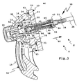
- Figur 1
- eine perspektivische Schrägansicht einer erfin- dungsgemäßen Anhängekupplung,
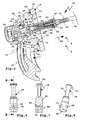
- Figur 2
- die Anhängekupplung gemäß
Figur 1 , jedoch bei ent- ferntem Kupplungsarm, - Figur 3
- eine Querschnittsansicht der Anhängekupplung ent- lang einer Schnittlinie A-A in
Figur 1 in Verriege- lungsstellung und Sperrstellung, - Figur 4
- die Ansicht etwa entsprechend
Figur 3 bei noch ver- riegelter, bereits entsperrter Verriegelungsein- richtung, - Figur 5
- die Anhängekupplung gemäß
Figuren 3 ,4 entsperrt und entriegelt, - Figur 6
- eine Seitenansicht eines Verriegelungskörpers der Anhängekupplung gemäß der vorstehenden Figuren,
- Figur 7
- eine Querschnittsansicht des Verriegelungskörpers gemäß
Figur 6 etwa entlang einer Schnittlinie B-B inFigur 6 , - Figur 8
- den Verriegelungskörper gemäß
Figuren 6, 7 in einer perspektivischen Schrägansicht, - Figur 9
- ein Sperr-Betätigungsglied der Anhängekupplung ge- mäß der vorstehenden Figuren in Seitenansicht,
Figur 10- eine Querschnittsansicht des Sperr- Betätigungsglieds gemäß
Figur 9 etwa entlang einer Schnittlinie C-C inFigur 9 , Figur 11- eine perspektivische Schrägansicht und
Figur 12- eine Draufsicht des Sperr-
Betätigungsglieds gemäß Figuren 9, 10 .
- FIG. 1
- 3 is an oblique perspective view of a trailer coupling according to the invention;
- FIG. 2
- the hitch according to
FIG. 1 , but with the coupling arm removed, - FIG. 3
- a cross-sectional view of the trailer coupling along a section line AA in
FIG. 1 in locking position and locked position, - FIG. 4
- the view about accordingly
FIG. 3 with locking device already locked, already unlocked, - FIG. 5
- the hitch according to
Figures 3 .4 unlocked and unlocked, - FIG. 6
- a side view of a locking body of the hitch according to the preceding figures,
- FIG. 7
- a cross-sectional view of the locking body according to
FIG. 6 approximately along a section line BB inFIG. 6 . - FIG. 8
- the locking body according to
FIGS. 6, 7 in a perspective oblique view, - FIG. 9
- a locking actuator of the trailer coupling according to the preceding figures in side view,
- FIG. 10
- a cross-sectional view of the locking actuator according to
FIG. 9 approximately along a section line CC inFIG. 9 . - FIG. 11
- a perspective oblique view and
- FIG. 12
- a plan view of the locking actuator according to
FIGS. 9, 10 ,
Eine Anhängekupplung 10 zum Ankuppeln eines Anhängers 11 an ein Kraftfahrzeug 12 umfasst einen Halter 13, der an einem schematisch dargestellten Querträger 14 des Kraftfahrzeugs 12 befestigbar, beispielsweise anschraubbar, anschweißbar oder dergleichen ist. Der Halter 13 hält einen Kupplungsarm 15.A
Der Kupplungsarm 15 ist mittels eines Schwenk-Schiebelagers 16 einer Lageranordnung 17 schwenkbeweglich und schiebebeweglich an dem Halter 13 gelagert.The
Ein Halsabschnitt 19 des Kupplungsarms 15 steht von einem am Halter 13 beweglich gelagerten Arm-Lagerteil 18 ab und trägt an seinem freien, vom Halter 13 entfernten Ende einen Kugelkopf 20 zum Ankuppeln des Anhängers 11.A
Mit Hilfe der Lageranordnung 17 ist der Kupplungsarm 15 zwischen seiner in
Zumindest in der Arbeitsstellung, vorzugsweise auch in der Nichtgebrauchsstellung, ist der Kupplungsarm 15 mittels des Arm-Lagerteils 18 mit einer Verriegelungseinrichtung 22 verriegelbar. Die Verriegelungseinrichtung 22 ist durch ein Betätigungsorgan 23 aus ihrer Verriegelungsstellung V (
Die Verriegelungseinrichtung 22 kann mit dem Betätigungsorgan 23, das ein Zugorgan 24 umfasst, von der Verriegelungsstellung V in die Entriegelungsstellung E verstellt werden. Das Betätigungsorgan 23 erstreckt sich zwischen der Verriegelungseinrichtung 22 am Halter 13 und einer Handbetätigungseinrichtung 25 zur manuellen Betätigung des Betätigungsorgans 23. Das Zugorgan 24 umfasst einen Bowdenzug 28. Der Bowdenzug 28 kann beispielsweise vom Außenbereich des Kraftfahrzeugs 12 in einen Innenraum, beispielsweise ein Gepäckabteil, verlaufen, wo die Handbetätigungseinrichtung 25 vorteilhaft angeordnet ist.The locking
Eine Handbetätigungseinrichtung kann z.B. auch einen Bedienhebel oder eine Hebelanordnung umfassen. Der Bedienhebel kann im Außenbereich des Kraftfahrzeugs oder auch in dessen Innenraum vorgesehen sein.A manual override device may e.g. Also include an operating lever or a lever assembly. The operating lever may be provided in the exterior of the motor vehicle or in the interior thereof.
Die Handbetätigungseinrichtung 25 umfasst ein Handrad 26, das an einem Gehäuse 27 drehbar ist, um das Zugorgan 24 zu ziehen. Prinzipiell wäre anstelle des Bowdenzugs 28 auch ein einfacher Seilzug, eine Zugstange oder dergleichen ohne weiteres möglich. Der Bowdenzug 28 erlaubt jedoch eine relativ freie Verlegung an dem Kraftfahrzeug 12.The
Eine am Querträger 14 befestigte Trägerplatte 29 des Halters 13 trägt einen Lagerkopf 30, auf dem das Arm-Lagerteil 18 schiebebeweglich und schwenkbeweglich gelagert ist. Durch eine Verschiebebewegung entlang einer Schiebeachse SA ist das Arm-Lagerteil 18 auf dem Lagerkopf 30 von der Trägerplatte 29 weg oder zu dieser hin verschieblich. Wenn das Arm-Lagerteil 18 von der Trägerplatte 29 weg verschoben ist, sind Formschlusskonturen 31 am Halter 13 und Formschlusskonturen 32 am Arm-Lagerteil 18 außer Eingriff, so dass das Arm-Lagerteil 18 schwenkbeweglich bezüglich des Halters 13 ist.A fortified on the
Wenn das Arm-Lagerteil 18 hingegen entlang der Schiebeachse SA zum Halter 13 beziehungsweise zur Trägerplatte 29 hin verschoben ist, greifen die Formschlusskonturen 31, 32 formschlüssig ineinander und verriegeln so das Arm-Lagerteil 18 am Halter 13 zumindest drehbeweglich. Die Formschlusskonturen 31 umfassen ringförmig um den Lagerkopf 30 herum angeordnete Kalotten 33, in die Kugeln 34 eingreifen, die ihrerseits an einer dem Halter 13 zugewandten Stirnseite 35 des Arm-Lagerteils 18 angeordnet sind.On the other hand, when the
Es versteht sich, dass anstelle von Kugeln und Kalotten beispielsweise auch bolzenartige Vorsprünge, die in korrespondierende Sacklöcher eingreifen, möglich sind. Ferner könnte auch mindestens ein männliches Formschlussteil ohne weiteres auch am Halter, mindestens ein weibliches Formschlussteil am Arm-Lagerteil angeordnet sein.It is understood that instead of balls and caps, for example, bolt-like projections which engage in corresponding blind holes, are possible. Furthermore, at least one male form-fitting part could also readily be arranged on the holder, at least one female form-fitting part on the arm bearing part.
Die Verriegelungseinrichtung 22 ist geschützt in einem Innenraum 36 einer Hohlwelle 37 des Lagerkopfs 30 angeordnet. In dem Innenraum 36 ist ein Verriegelungskörper 38 in einem Linearführungskanal 39 linear verschieblich gelagert. Der Verriegelungskörper 38 umfasst vorliegend einen Verdrängerkörper 40 zum Verdrängen von Verriegelungselementen 56. Der Verriegelungskörper 38 ist im Wesentlichen in einem vorderen, freien Abschnitt 41 des Lagerkopfs 30 beziehungsweise der Hohlwelle 37 mit einem kleineren Durchmesser angeordnet. Der Abschnitt 41 steht vor einen Basisabschnitt 42 des Lagerkopfs 30 vor, der einen im Vergleich zum Abschnitt 41 größeren Durchmesser hat und eine Befestigungsbasis zur Befestigung an der Trägerplatte 29 bildet. Am Basisabschnitt 42 sind Schraublöcher 43 angeordnet, die sich in der Schieberichtung SA erstrecken und für Schrauben zum Anschrauben an die Trägerplatte 29 vorgesehen sind. Es versteht sich, dass der Lagerkopf 30 auch von der Trägerplatte 29 her schraubbar oder in sonstiger Weise mit dieser verbunden oder gar mit ihr einstückig sein kann.The locking
Der Basisabschnitt 42 des Lagerkopfs 30 hat eine Aufnahme 44 für eine zum Anschluss des Betätigungsorgans 23 vorgesehenes Anschlusseinrichtung 45, die einen Durchbruch 46 an der Trägerplatte 29 durchdringt und nach hinten vor die Trägerplatte 29 vorsteht. Die Anschlusseinrichtung 45 hat eine teilweise als Führungskanal ausgestaltete Federkammer 48, die sich an die Abschnitte 41, 42 anschließt und somit zu dem Innenraum 36 gehört, in dem die Verriegelungseinrichtung 22 angeordnet ist.The
Der Innenraum 36 ist jeweils endseitig verschlossen, einerseits eine Kappe 92, die auf den vom Halter 13 entfernten Endbereich des Arm-Lagerteils 18 aufgesetzt ist, und andererseits durch einen Deckel 47 am freien Ende der Anschlusseinrichtung 45. Dadurch ist die Verriegelungseinrichtung 22 vor Umwelteinflüssen optimal geschütztThe
Weiterhin trägt zu ihrem mechanischen Schutz bei, dass das Arm-Lagerteil 18 sozusagen auf den Lagerkopf 30 aufgesetzt ist und diesen mantelt. Ferner ist eine Dichtung 93 zwischen der Trägerplatte 29 und dem Arm-Lagerteil 18 angeordnet. Die Dichtung 93 ist eine Ringdichtung, die am Arm-Lagerteil 18 angeordnet ist und die Formschlusskonturen 31, 32 umgibt und vor Umwelteinflüssen schützt.Furthermore contributes to their mechanical protection that the arm-bearing
Das Arm-Lagerteil 18 hat eine im Wesentlichen stumpfkegelige Form.The
Der Deckel 47 hat einen Durchbruch für ein Zugseil 51, das im Innern des Betätigungsorgans 23 verläuft. Das Zugseil 51 ist durch ein Anschlussstück 52 am Deckel 47 hindurchgeführt. Das Anschlussstück 52 dient zum Anschluss des Bowdenzugs 28 an den Halter 13 beziehungsweise die Verriegelungseinrichtung 22.The
In der Federkammer 48 ist eine Feder 49 einer Federanordnung 50 angeordnet, die sich an dem Anschlussstück 52 abstützt.In the
Das Zugseil 51 ist durch einen Innenraum der als Schraubenfeder ausgestalteten Feder 49 geführt und an einer Halterung 53 eines Sperr-Betätigungsglieds 54 festgelegt, beispielsweise eingeschraubt, verklemmt, verklebt oder dergleichen.The
Das Sperr-Betätigungsglied 54 ist mittels einer Kopplungsanordnung 55 in Zugrichtung des Zugseils 51 mit dem Verriegelungskörper 38 zuggekoppelt. Ferner stützt sich die als Druckfeder ausgestaltete Feder 49 an ihrem dem Deckel 47 entgegengesetzten Ende hinten am Sperr-Betätigungsglied 54 ab und drückt dieses in Richtung des Verriegelungskörpers 38. Mithin betätigt also die Federanordnung 50 den Verdrängerkörper 40 über das zwischengeschaltete Sperr-Betätigungsglied 54 in seine Verriegelungsstellung V.The blocking
In der Verriegelungsstellung V verdrängt der Verriegelungskörper 38 in seiner Eigenschaft als Verdrängerkörper 40 die Verriegelungselemente 56. Die Verriegelungselemente 56 sind in Führungskanälen 57 beweglich gelagert, die sich zwischen einer Außenfläche 58 der Hohlwelle 37 und dem Innenraum 36 erstrecken. Die Verriegelungselemente 56 sind vorliegend Kugeln, wobei auch andere Formschlusselemente, beispielsweise Bolzen, Rollen oder dergleichen ohne weiteres möglich sind. Der Verdrängerkörper 40 verdrängt in der Verriegelungsstellung V mit einer Verdrängerfläche 59 die Verriegelungselemente 56 nach radial außen durch die Führungskanäle 57 hindurch, so dass sie vor die Außenfläche 58 vorstehen. Dort greifen die Verriegelungselemente 56 in eine Verriegelungsaufnahme 60 im Innenraum des Arm-Lagerteils 18 ein. Die Verriegelungsaufnahme 60 ist mit einer derartigen Kontur ausgestaltet, dass die nach radial außen verdrängten Verriegelungselemente 56 eine Andrückkraft 63 in Richtung des Halters 13 auf das Arm-Lagerteil 18 ausüben.In the locking position V of the locking
Die Verriegelungsaufnahme 60 ist ringförmig, z.B. als eine Kugelsitzrinne ausgestaltet, so dass es auf die jeweilige Drehposition des Arm-Lagerteils 18 bezüglich des Halters 13 insoweit nicht ankommt. Beispielsweise ist die Verriegelungsaufnahme 60 an einem Ringeinsatz 62 angeordnet, der in einer Lageraufnahme 61 des Arm-Lagerteils 18 festgelegt ist.The latch receptacle 60 is annular, e.g. designed as a ball seat trough, so that it does not depend on the respective rotational position of the
Korrespondierend mit den unterschiedlichen Durchmessern des Abschnitts 41 und des Basisabschnitts 42 des Lagerkopfs 30 ist die Lageraufnahme 61 stufig.Corresponding to the different diameters of the
Zwar hat die Verdrängerfläche 59 eine selbstsperrende Schrägneigung von beispielsweise etwa 2 bis 5°, damit eine Rückwirkung der Verriegelungselemente 56 in Richtung der Entriegelungsstellung E den Verdrängerkörper 40 bzw. Verriegelungskörper 38 an sich nicht in die Entriegelungsstellung E verdrängen kann. Durch die Federkraft der Feder 49, die über die Verdrängerfläche 59, die Verriegelungselemente 56 (Kugeln) in die Lageraufnahmen 61 in die Andrückkraft 63 umgelenkt wird, bleibt an sich das Arm-Lagerteil 18 sicher am Halter 13 verriegelt.Although the
Eine erfindungsgemäße Sperre schafft eine zusätzliche Sicherheit:
Mehrere Sperrkörper 64, beispielsweise zwei oder drei, vorzugsweise Kugeln, Wälzkörper oder sonstige, beweglich gelagerte Sperr-Formschlusskörper,sperren den Verriegelungskörper 38 in der Verriegelungsstellung V gegen einer Entriegelungsbewegung in Richtung der EntriegelungsstellungE. Die Sperrkörper 64 sind inSperrkörperführungen 65 desVerriegelungskörpers 38 schiebebeweglich gelagert.Die Sperrkörperführungen 65 verlaufen quer, vorliegend senkrecht quer,zu dem Linearführungskanal 39 zur linearen Führung desVerriegelungskörpers 38.
- Several blocking
bodies 64, for example two or three, preferably balls, rolling elements or other movably mounted locking positive-locking bodies, lock the lockingbody 38 in the locking position V against an unlocking movement in the direction of the unlocking position E.The blocking bodies 64 are slidable in locking body guides 65 of the lockingbody 38 stored. The blocking body guides 65 extend transversely, in the present case perpendicularly transversely to thelinear guide channel 39 for linear guidance of the locking body 38th
Damit die Entsperrbetätigung des Sperrkörpers 64 der Entriegelungsbewegung des Verriegelungskörpers 38 vorausgeht, ist die Kopplungsanordnung 55 vorgesehen. Die Kopplungsanordnung 55 koppelt den Verriegelungskörper 38 mit einem Freigang, z.B. mit einem Längsspiel, entlang einer Zugrichtung 66 (insbesondere parallel zur Schiebeachse SA) mit dem Sperr-Betätigungsglied 54, das mit dem Zugorgan 24 verbunden ist.Thus, the Entsperrbetätigung the locking
Das Sperr-Betätigungsglied 54 enthält einen Zugabschnitt 67 mit einer Halteaufnahme 68, die von einem Halteglied 69 durchdrungen ist. Das Halteglied 69 ist fest mit dem Verriegelungskörper 38 verbunden. Das Halteglied 69 umfasst beispielsweise einen Querbolzen, der die Halteaufnahme 68 durchdringt und in Aufnahmen 70 des Verriegelungskörpers 38 aufgenommen ist. Das Halteglied 69 hat innerhalb der Aufnahmen 70, die als Langlöcher ausgestaltet sind, bezüglich der Zugrichtung 66 ein Freigang-Spiel. Der Zugabschnitt 67 und das Halteglied 69 bilden eine Art Zuganker 71The locking
Eine Entriegelung der Verriegelungseinrichtung 22 verläuft nun folgendermaßen:
- Zunächst
wirkt das Zugorgan 24 nur auf das Sperr-Betätigungsglied 54 und verlagert dieses inZugrichtung 66, wodurch der Sperrkörper 64 von seiner Sperrstellung S in die Freigabestellung F verstellt wird.Das Halteglied 69 gleitet dabei entlang der Zugrichtung 66 inder Halteaufnahme 68.Der Verriegelungskörper 38 bleibt noch in der Verriegelungsstellung V.Die beiden Komponenten 54 und 38 sind bei diesem ersten Betätigungsabschnitt durch das Spiel der Kopplungsanordnung 55 zugentkoppelt.
- First, the pulling
member 24 acts only on the lockingactuator 54 and moves it in the pullingdirection 66, whereby the lockingbody 64 is moved from its blocking position S to the release position F. The holdingmember 69 slides along the pullingdirection 66 in the holdingreceptacle 68. The lockingbody 38 still remains in the locking position V. The twocomponents coupling assembly 55.
Wenn das Halteglied 69 in den Aufnahmen 70 einen für das Entsperren des Sperrkörpers 64 erforderlichen Betätigungsweg durchlaufen hat, schlägt es an dem Verriegelungskörper 38 zugewandten Enden der Aufnahmen 70 an. Das Sperr-Betätigungsglied 54 ist dann so positioniert, dass die Sperrkörper 64 an Schrägflächen 72 entlang in Vertiefungen 73 am Sperr-Betätigungsglied 54 gleiten können, d.h. in ihre Freigabestellung F fallen. Somit ist der Weg des Verriegelungskörpers 38 in die Entriegelungsstellung E frei. Das Sperr-Betätigungsglied 54 nimmt bei einer weiteren Betätigung des Zugorgans 24 den Verriegelungskörper 38 in die Entriegelungsstellung E mit.When the holding
Bei dieser Entriegelung wird zunächst die Verdrängerfläche 59 unterhalb der Verriegelungselemente 56 wegbewegt, so dass ein Freiraumabschnitt 74 des Verriegelungskörpers 38 unterhalb der Verriegelungselemente 56 positioniert ist. Der Freiraumabschnitt 74 gibt einen Bewegungsfreiraum für die Verriegelungselemente 56 frei, so dass diese nach radial innen durch die Führungskanäle 57 hindurch in Richtung des Innenraums 36 beweglich sind, um aus den Verriegelungsaufnahmen 60 herauszugelangen und somit die Verriegelung des Kupplungsarms 15 am Halter 13 aufzuheben. Die Andrückkraft 63 ist dann gleich Null, so dass die Formschlusskonturen 31, 32 außer Eingriff gelangen können.In this unlocking, first the displacing
Das Arm-Lagerteil 18 könnte aber prinzipiell am Halter 13 festbacken, beispielsweise nach langem Fahrbetrieb. Auch für diese Situation sind bei der Anhängekupplung 10 Maßnahmen getroffen. An den Freiraumabschnitt 74 des Verdrängerkörpers 40 schließen sich Schrägflächen 75 zum Betätigen von mindestens einem, vorzugsweise zwei oder drei Entriegelungskörpern 76 an, die in Führungskanälen 77 ähnlich den Führungskanälen 57 beweglich gelagert sind. Die Schrägflächen 75 drücken die Entriegelungskörper 76, vorzugsweise Kugeln, nach radial außen durch die Führungskanäle 77 hindurch in Entriegelungsaufnahmen 78 am Ringeinsatz 62 und erzeugen dadurch eine Ablösekraft 79 zum Ablösen des Arm-Lagerteils 18 vom Halter 13. Die Ablösekraft 79 und die Andrückkraft 63 sind einander entgegengesetzt.The arm-bearing
Die Feder 49 drückt in Richtung der Verriegelungsstellung V auf das Sperr-Betätigungsglied 54 und dieses wiederum auf den Verriegelungskörper 38.The
Ein Kopfbereich 80 des Sperr-Betätigungsglieds 54 ist in einem als Führungskanal oder Führungsaufnahme ausgestalteten Innenraum 81 des Verriegelungskörpers 38 aufgenommen und dort beweglich gelagert. Der Innenraum 81 ist im Wesentlichen hohlzylindrisch, wobei dessen Innenflächen zumindest teilweise Führungsflächen für einen ebenfalls zylindrischen Führungsabschnitt 82 des Kopfbereichs 80 aufweist. Die Vertiefungen 73 erstrecken sich von einer freien Stirnseite des Kopfbereichs 80 zum Führungsabschnitt 82 hin. Die Vertiefungen 73 sind beispielsweise wannenartig oder kuhlenartig ausgestaltet.A
Zwischen dem Kopfbereich 80 und einem die Halterung 53 für das Betätigungsorgan 23 aufweisenden Halteabschnitt 83 befindet sich ein Übertragungs- und Führungsabschnitt 84 des Sperr-Betätigungsglieds 54. Der Übertragungs- und Führungsabschnitt 84 umfasst einen vorliegend flanschartigen, jedenfalls teilringförmigen oder ringförmigen Vorsprung 85. Der Übertragungs-/Führungsabschnitt 84 ist stets außerhalb des Innenraums 81 und hat zum einen eine Führungsfunktion der Gestalt, dass er an der Innenwand der Federkammer 48 geführt ist, die insoweit einen Führungskanal bereitstellt, und zum anderen Druckkräfte der Feder 49 auf den Verriegelungskörper 38 überträgt. Somit bilden also einander entgegengesetzte, dem Kopfbereich 80 und dem Halteabschnitt 83 zugewandte Ober- und Unterseiten des Übertragungs- und Führungsabschnitts 84 Übertragungsflächen 86 zur Übertragung der Kräfte der Federanordnung 50 auf den Verriegelungskörper. Der Vorsprung 85 bildet sozusagen einen Stützvorsprung, an dem die Feder 49 anschlägt und der andererseits an einer dem Sperr-Betätigungsglied 54 zugewandten Stirnseite des Verriegelungskörpers 38 anschlägt. Der Halteabschnitt 83 steht in einen Innenraum der Feder 49 vor, d.h. er hat einen geringeren Durchmesser als der Vorsprung 85.Between the
Das Sperr-Betätigungsglied 54 betätigt, zweckmäßigerweise mit den Schrägflächen 72, die beiden Sperrkörper 64 nach radial außen durch die Sperrkörperführungen 65 des Verriegelungskörpers 38 hindurch, so dass sie in der Sperrstellung S in Sperr-Ausnehmungen 87 am Halter 13 eindringen. Die Sperr-Ausnehmungen 87 sind beispielsweise Erweiterungen des Linearführungskanals 39. Allerdings stehen die Sperrkörper 64 nur soweit in die Sperr-Ausnehmungen 87 vor eine Außenfläche des Verriegelungskörpers 38 vor, dass sie noch zumindest teilweise in den Sperrkörperführungen 65 sind. In der Sperrstellung S stützt sich somit der Verriegelungskörper 38 an den Sperrkörpern 64 ab, die sich ihrerseits an Anschlagflächen 88 der Sperr-Ausnehmungen 87 abstützen. Die Sperr-Ausnehmungen 87 sind beispielsweise in der Art von Taschen ausgestaltet. Die Anschlagflächen 88 weisen vorzugsweise mit den Konturen der Sperrkörper 64 korrelierende Innenkonturen auf. Sie sind beim Ausführungsbeispiel z.B. ausgerundet.The blocking
Zwar könnte man z.B. im wesentlichen kalottenförmige Sperr-Ausnehmungen bei einer erfindungsgemäßen Anhängekupplung vorsehen. Vorteilhaft weisen erfindungsgemäße Sperr-Ausnehmungen jedoch eine Länge auf, die ein Nachstellen des Verriegelungskörpers in Richtung seiner Verriegelungsstellung ermöglicht. So haben z.B. die Sperr-Ausnehmungen 87 vorteilhaft eine Längserstreckung entlang der Schiebeachse SA.Although one could for example provide essentially dome-shaped locking recesses in a trailer coupling according to the invention. Advantageously, however, locking recesses according to the invention have a length which is an adjustment of the locking body in the direction of its locking position allows. For example, the locking recesses 87 advantageously have a longitudinal extent along the sliding axis SA.
Am freien Ende oder Kopf des Verriegelungskörpers 38 ist zweckmäßigerweise eine Aufnahme 89 für einen Sensor 90 vorhanden, mit dem eine jeweilige Verriegelungsstellung V oder Entriegelungsstellung B des Verriegelungskörpers 38 ermittelbar ist.At the free end or head of the locking
Claims (15)
Applications Claiming Priority (1)
| Application Number | Priority Date | Filing Date | Title |
|---|---|---|---|
| DE102009033911A DE102009033911A1 (en) | 2009-07-20 | 2009-07-20 | Towing |
Publications (3)
| Publication Number | Publication Date |
|---|---|
| EP2277724A2 true EP2277724A2 (en) | 2011-01-26 |
| EP2277724A3 EP2277724A3 (en) | 2011-08-31 |
| EP2277724B1 EP2277724B1 (en) | 2013-11-20 |
Family
ID=43036060
Family Applications (1)
| Application Number | Title | Priority Date | Filing Date |
|---|---|---|---|
| EP10006839.4A Active EP2277724B1 (en) | 2009-07-20 | 2010-07-02 | Tow bar |
Country Status (2)
| Country | Link |
|---|---|
| EP (1) | EP2277724B1 (en) |
| DE (1) | DE102009033911A1 (en) |
Cited By (4)
| Publication number | Priority date | Publication date | Assignee | Title |
|---|---|---|---|---|
| EP2792514A3 (en) * | 2013-04-21 | 2014-11-05 | WESTFALIA - Automotive GmbH | Trailer coupling |
| EP2875972A1 (en) * | 2013-11-08 | 2015-05-27 | WESTFALIA - Automotive GmbH | Draw bar with a fixing device |
| EP3736145A1 (en) * | 2019-05-09 | 2020-11-11 | Brink Towing Systems B.V. | Retractable towing hook arrangement |
| EP4324665A1 (en) * | 2022-08-18 | 2024-02-21 | Brink Towing Systems B.V. | A sealing arrangement for a retractable towing hook |
Families Citing this family (12)
| Publication number | Priority date | Publication date | Assignee | Title |
|---|---|---|---|---|
| DE102010043164B4 (en) * | 2010-10-29 | 2016-09-15 | Zf Friedrichshafen Ag | Ball swivel module for a trailer hitch |
| DE102011053506A1 (en) | 2011-09-12 | 2013-03-14 | Scambia Holdings Cyprus Ltd. | Towing |
| DE102013012525A1 (en) | 2013-07-27 | 2015-01-29 | Westfalia-Automotive Gmbh | Trailer coupling system for motor vehicles |
| DE102014015876A1 (en) * | 2014-10-22 | 2016-04-28 | Westfalia-Automotive Gmbh | Coupling device with a fixing device |
| EP3379222B1 (en) | 2017-03-22 | 2020-12-30 | Methode Electronics Malta Ltd. | Magnetoelastic based sensor assembly |
| US11135882B2 (en) | 2018-02-27 | 2021-10-05 | Methode Electronics, Inc. | Towing systems and methods using magnetic field sensing |
| DE18907724T1 (en) | 2018-02-27 | 2021-03-25 | Methode Electronics, Inc. | Towing systems and methods using magnetic field measurement |
| US11084342B2 (en) | 2018-02-27 | 2021-08-10 | Methode Electronics, Inc. | Towing systems and methods using magnetic field sensing |
| US11221262B2 (en) | 2018-02-27 | 2022-01-11 | Methode Electronics, Inc. | Towing systems and methods using magnetic field sensing |
| US11491832B2 (en) | 2018-02-27 | 2022-11-08 | Methode Electronics, Inc. | Towing systems and methods using magnetic field sensing |
| DE102019109398B4 (en) * | 2019-04-10 | 2021-05-27 | Dr. Ing. H.C. F. Porsche Aktiengesellschaft | trailer hitch |
| WO2023280956A1 (en) * | 2021-07-06 | 2023-01-12 | Westfalia-Automotive Gmbh | Trailer coupling with actuation contours and counter-bearing contours |
Citations (2)
| Publication number | Priority date | Publication date | Assignee | Title |
|---|---|---|---|---|
| EP1475253A1 (en) | 2003-05-07 | 2004-11-10 | Westfalia Automotive GmbH & Co. KG | Trailer coupling for motor vehicles |
| DE102008035987A1 (en) | 2008-08-01 | 2010-02-04 | Westfalia-Automotive Gmbh | Towing |
Family Cites Families (5)
| Publication number | Priority date | Publication date | Assignee | Title |
|---|---|---|---|---|
| DE19848487A1 (en) * | 1998-10-21 | 2000-05-04 | Oris Fahrzeugteile Riehle H | Trailer coupling |
| DE19902355A1 (en) * | 1999-01-21 | 2000-08-03 | Oris Fahrzeugteile Riehle H | Trailer coupling |
| US6860503B2 (en) * | 2002-11-13 | 2005-03-01 | Westfalia-Automotive Gmbh & Co. Kg | Retractile motor-vehicle trailer hitch |
| DE10323619B4 (en) * | 2003-05-26 | 2009-09-03 | Audi Ag | Removable hitch for vehicles, especially for motor vehicles |
| DE102004004501B4 (en) * | 2004-01-22 | 2021-07-01 | ACPS Automotive GmbH | Trailer coupling |
-
2009
- 2009-07-20 DE DE102009033911A patent/DE102009033911A1/en not_active Withdrawn
-
2010
- 2010-07-02 EP EP10006839.4A patent/EP2277724B1/en active Active
Patent Citations (2)
| Publication number | Priority date | Publication date | Assignee | Title |
|---|---|---|---|---|
| EP1475253A1 (en) | 2003-05-07 | 2004-11-10 | Westfalia Automotive GmbH & Co. KG | Trailer coupling for motor vehicles |
| DE102008035987A1 (en) | 2008-08-01 | 2010-02-04 | Westfalia-Automotive Gmbh | Towing |
Cited By (5)
| Publication number | Priority date | Publication date | Assignee | Title |
|---|---|---|---|---|
| EP2792514A3 (en) * | 2013-04-21 | 2014-11-05 | WESTFALIA - Automotive GmbH | Trailer coupling |
| EP2875972A1 (en) * | 2013-11-08 | 2015-05-27 | WESTFALIA - Automotive GmbH | Draw bar with a fixing device |
| EP3736145A1 (en) * | 2019-05-09 | 2020-11-11 | Brink Towing Systems B.V. | Retractable towing hook arrangement |
| EP4324665A1 (en) * | 2022-08-18 | 2024-02-21 | Brink Towing Systems B.V. | A sealing arrangement for a retractable towing hook |
| WO2024037878A1 (en) * | 2022-08-18 | 2024-02-22 | Brink Towing Systems B.V. | A sealing arrangement for a retractable towing hook |
Also Published As
| Publication number | Publication date |
|---|---|
| EP2277724A3 (en) | 2011-08-31 |
| DE102009033911A1 (en) | 2011-01-27 |
| EP2277724B1 (en) | 2013-11-20 |
Similar Documents
| Publication | Publication Date | Title |
|---|---|---|
| EP2277724B1 (en) | Tow bar | |
| EP2474430B1 (en) | Tow bar | |
| EP1902870B1 (en) | Towing device for a towing vehicle | |
| EP2792514B1 (en) | Trailer coupling | |
| EP2567835B2 (en) | Tow bar | |
| EP2502763B1 (en) | Tow bar | |
| DE102006008837A1 (en) | Towbar for motor vehicles | |
| EP2017097A1 (en) | Towbar for motor vehicles | |
| EP2792513B1 (en) | Trailer coupling | |
| EP2229539B1 (en) | Mounting aid and mounting method | |
| EP2657051B1 (en) | Coupling assembly for a rear carrier | |
| EP1946947B1 (en) | Coupling device with an interlocking device with activation ring | |
| EP2799261B1 (en) | Trailer coupling | |
| EP2412550B1 (en) | Tow bar | |
| EP3012128B1 (en) | Coupling device comprising a fixing unit | |
| EP2316673B1 (en) | Connection device for a trailer coupling or a load bearer | |
| EP2796305B1 (en) | Trailer coupling | |
| EP2796304B1 (en) | Tow bar | |
| DE102014005881A1 (en) | Towing | |
| EP2796303B1 (en) | Trailer coupling | |
| DE102004033041A1 (en) | Towing hitch for motor vehicles | |
| DE102007003773A1 (en) | Towing device for towing vehicle, has positive locking element movably supported at positive locking element bearing, and engaging in locking position in positive locking receiver at outer circumference of coupling arm | |
| DE102013007123A1 (en) | Towing |
Legal Events
| Date | Code | Title | Description |
|---|---|---|---|
| PUAI | Public reference made under article 153(3) epc to a published international application that has entered the european phase |
Free format text: ORIGINAL CODE: 0009012 |
|
| AK | Designated contracting states |
Kind code of ref document: A2 Designated state(s): AL AT BE BG CH CY CZ DE DK EE ES FI FR GB GR HR HU IE IS IT LI LT LU LV MC MK MT NL NO PL PT RO SE SI SK SM TR |
|
| AX | Request for extension of the european patent |
Extension state: BA ME RS |
|
| PUAL | Search report despatched |
Free format text: ORIGINAL CODE: 0009013 |
|
| AK | Designated contracting states |
Kind code of ref document: A3 Designated state(s): AL AT BE BG CH CY CZ DE DK EE ES FI FR GB GR HR HU IE IS IT LI LT LU LV MC MK MT NL NO PL PT RO SE SI SK SM TR |
|
| AX | Request for extension of the european patent |
Extension state: BA ME RS |
|
| RIC1 | Information provided on ipc code assigned before grant |
Ipc: B60D 1/06 20060101AFI20110727BHEP Ipc: B60D 1/54 20060101ALI20110727BHEP |
|
| 17P | Request for examination filed |
Effective date: 20120210 |
|
| GRAP | Despatch of communication of intention to grant a patent |
Free format text: ORIGINAL CODE: EPIDOSNIGR1 |
|
| INTG | Intention to grant announced |
Effective date: 20130701 |
|
| GRAS | Grant fee paid |
Free format text: ORIGINAL CODE: EPIDOSNIGR3 |
|
| GRAA | (expected) grant |
Free format text: ORIGINAL CODE: 0009210 |
|
| AK | Designated contracting states |
Kind code of ref document: B1 Designated state(s): AL AT BE BG CH CY CZ DE DK EE ES FI FR GB GR HR HU IE IS IT LI LT LU LV MC MK MT NL NO PL PT RO SE SI SK SM TR |
|
| REG | Reference to a national code |
Ref country code: GB Ref legal event code: FG4D Free format text: NOT ENGLISH |
|
| REG | Reference to a national code |
Ref country code: CH Ref legal event code: EP |
|
| REG | Reference to a national code |
Ref country code: AT Ref legal event code: REF Ref document number: 641362 Country of ref document: AT Kind code of ref document: T Effective date: 20131215 |
|
| REG | Reference to a national code |
Ref country code: IE Ref legal event code: FG4D Free format text: LANGUAGE OF EP DOCUMENT: GERMAN |
|
| REG | Reference to a national code |
Ref country code: DE Ref legal event code: R096 Ref document number: 502010005399 Country of ref document: DE Effective date: 20140116 |
|
| REG | Reference to a national code |
Ref country code: NL Ref legal event code: VDEP Effective date: 20131120 |
|
| REG | Reference to a national code |
Ref country code: LT Ref legal event code: MG4D |
|
| PG25 | Lapsed in a contracting state [announced via postgrant information from national office to epo] |
Ref country code: IS Free format text: LAPSE BECAUSE OF FAILURE TO SUBMIT A TRANSLATION OF THE DESCRIPTION OR TO PAY THE FEE WITHIN THE PRESCRIBED TIME-LIMIT Effective date: 20140320 Ref country code: SE Free format text: LAPSE BECAUSE OF FAILURE TO SUBMIT A TRANSLATION OF THE DESCRIPTION OR TO PAY THE FEE WITHIN THE PRESCRIBED TIME-LIMIT Effective date: 20131120 Ref country code: FI Free format text: LAPSE BECAUSE OF FAILURE TO SUBMIT A TRANSLATION OF THE DESCRIPTION OR TO PAY THE FEE WITHIN THE PRESCRIBED TIME-LIMIT Effective date: 20131120 Ref country code: HR Free format text: LAPSE BECAUSE OF FAILURE TO SUBMIT A TRANSLATION OF THE DESCRIPTION OR TO PAY THE FEE WITHIN THE PRESCRIBED TIME-LIMIT Effective date: 20131120 Ref country code: LT Free format text: LAPSE BECAUSE OF FAILURE TO SUBMIT A TRANSLATION OF THE DESCRIPTION OR TO PAY THE FEE WITHIN THE PRESCRIBED TIME-LIMIT Effective date: 20131120 Ref country code: NO Free format text: LAPSE BECAUSE OF FAILURE TO SUBMIT A TRANSLATION OF THE DESCRIPTION OR TO PAY THE FEE WITHIN THE PRESCRIBED TIME-LIMIT Effective date: 20140220 Ref country code: NL Free format text: LAPSE BECAUSE OF FAILURE TO SUBMIT A TRANSLATION OF THE DESCRIPTION OR TO PAY THE FEE WITHIN THE PRESCRIBED TIME-LIMIT Effective date: 20131120 |
|
| PG25 | Lapsed in a contracting state [announced via postgrant information from national office to epo] |
Ref country code: ES Free format text: LAPSE BECAUSE OF FAILURE TO SUBMIT A TRANSLATION OF THE DESCRIPTION OR TO PAY THE FEE WITHIN THE PRESCRIBED TIME-LIMIT Effective date: 20131120 Ref country code: LV Free format text: LAPSE BECAUSE OF FAILURE TO SUBMIT A TRANSLATION OF THE DESCRIPTION OR TO PAY THE FEE WITHIN THE PRESCRIBED TIME-LIMIT Effective date: 20131120 |
|
| PG25 | Lapsed in a contracting state [announced via postgrant information from national office to epo] |
Ref country code: PT Free format text: LAPSE BECAUSE OF FAILURE TO SUBMIT A TRANSLATION OF THE DESCRIPTION OR TO PAY THE FEE WITHIN THE PRESCRIBED TIME-LIMIT Effective date: 20140320 |
|
| PG25 | Lapsed in a contracting state [announced via postgrant information from national office to epo] |
Ref country code: EE Free format text: LAPSE BECAUSE OF FAILURE TO SUBMIT A TRANSLATION OF THE DESCRIPTION OR TO PAY THE FEE WITHIN THE PRESCRIBED TIME-LIMIT Effective date: 20131120 |
|
| REG | Reference to a national code |
Ref country code: DE Ref legal event code: R097 Ref document number: 502010005399 Country of ref document: DE |
|
| PG25 | Lapsed in a contracting state [announced via postgrant information from national office to epo] |
Ref country code: RO Free format text: LAPSE BECAUSE OF FAILURE TO SUBMIT A TRANSLATION OF THE DESCRIPTION OR TO PAY THE FEE WITHIN THE PRESCRIBED TIME-LIMIT Effective date: 20131120 Ref country code: PL Free format text: LAPSE BECAUSE OF FAILURE TO SUBMIT A TRANSLATION OF THE DESCRIPTION OR TO PAY THE FEE WITHIN THE PRESCRIBED TIME-LIMIT Effective date: 20131120 Ref country code: SK Free format text: LAPSE BECAUSE OF FAILURE TO SUBMIT A TRANSLATION OF THE DESCRIPTION OR TO PAY THE FEE WITHIN THE PRESCRIBED TIME-LIMIT Effective date: 20131120 Ref country code: CZ Free format text: LAPSE BECAUSE OF FAILURE TO SUBMIT A TRANSLATION OF THE DESCRIPTION OR TO PAY THE FEE WITHIN THE PRESCRIBED TIME-LIMIT Effective date: 20131120 |
|
| REG | Reference to a national code |
Ref country code: DE Ref legal event code: R082 Ref document number: 502010005399 Country of ref document: DE Representative=s name: BREGENZER, MICHAEL, DIPL.-ING., DE Ref country code: DE Ref legal event code: R082 Ref document number: 502010005399 Country of ref document: DE Representative=s name: PATENTANWAELTE BREGENZER UND REULE PARTNERSCHA, DE |
|
| PLBE | No opposition filed within time limit |
Free format text: ORIGINAL CODE: 0009261 |
|
| STAA | Information on the status of an ep patent application or granted ep patent |
Free format text: STATUS: NO OPPOSITION FILED WITHIN TIME LIMIT |
|
| PG25 | Lapsed in a contracting state [announced via postgrant information from national office to epo] |
Ref country code: DK Free format text: LAPSE BECAUSE OF FAILURE TO SUBMIT A TRANSLATION OF THE DESCRIPTION OR TO PAY THE FEE WITHIN THE PRESCRIBED TIME-LIMIT Effective date: 20131120 |
|
| 26N | No opposition filed |
Effective date: 20140821 |
|
| REG | Reference to a national code |
Ref country code: DE Ref legal event code: R097 Ref document number: 502010005399 Country of ref document: DE Effective date: 20140821 |
|
| REG | Reference to a national code |
Ref country code: DE Ref legal event code: R082 Ref document number: 502010005399 Country of ref document: DE Representative=s name: PATENTANWAELTE BREGENZER UND REULE PARTNERSCHA, DE |
|
| PG25 | Lapsed in a contracting state [announced via postgrant information from national office to epo] |
Ref country code: LU Free format text: LAPSE BECAUSE OF FAILURE TO SUBMIT A TRANSLATION OF THE DESCRIPTION OR TO PAY THE FEE WITHIN THE PRESCRIBED TIME-LIMIT Effective date: 20140702 Ref country code: SI Free format text: LAPSE BECAUSE OF FAILURE TO SUBMIT A TRANSLATION OF THE DESCRIPTION OR TO PAY THE FEE WITHIN THE PRESCRIBED TIME-LIMIT Effective date: 20131120 |
|
| REG | Reference to a national code |
Ref country code: CH Ref legal event code: PL |
|
| GBPC | Gb: european patent ceased through non-payment of renewal fee |
Effective date: 20140702 |
|
| REG | Reference to a national code |
Ref country code: IE Ref legal event code: MM4A |
|
| PG25 | Lapsed in a contracting state [announced via postgrant information from national office to epo] |
Ref country code: CH Free format text: LAPSE BECAUSE OF NON-PAYMENT OF DUE FEES Effective date: 20140731 Ref country code: LI Free format text: LAPSE BECAUSE OF NON-PAYMENT OF DUE FEES Effective date: 20140731 Ref country code: IT Free format text: LAPSE BECAUSE OF FAILURE TO SUBMIT A TRANSLATION OF THE DESCRIPTION OR TO PAY THE FEE WITHIN THE PRESCRIBED TIME-LIMIT Effective date: 20131120 |
|
| PG25 | Lapsed in a contracting state [announced via postgrant information from national office to epo] |
Ref country code: GB Free format text: LAPSE BECAUSE OF NON-PAYMENT OF DUE FEES Effective date: 20140702 |
|
| PG25 | Lapsed in a contracting state [announced via postgrant information from national office to epo] |
Ref country code: IE Free format text: LAPSE BECAUSE OF NON-PAYMENT OF DUE FEES Effective date: 20140702 |
|
| PG25 | Lapsed in a contracting state [announced via postgrant information from national office to epo] |
Ref country code: SM Free format text: LAPSE BECAUSE OF FAILURE TO SUBMIT A TRANSLATION OF THE DESCRIPTION OR TO PAY THE FEE WITHIN THE PRESCRIBED TIME-LIMIT Effective date: 20131120 Ref country code: MC Free format text: LAPSE BECAUSE OF FAILURE TO SUBMIT A TRANSLATION OF THE DESCRIPTION OR TO PAY THE FEE WITHIN THE PRESCRIBED TIME-LIMIT Effective date: 20131120 |
|
| REG | Reference to a national code |
Ref country code: FR Ref legal event code: PLFP Year of fee payment: 7 |
|
| PG25 | Lapsed in a contracting state [announced via postgrant information from national office to epo] |
Ref country code: MT Free format text: LAPSE BECAUSE OF FAILURE TO SUBMIT A TRANSLATION OF THE DESCRIPTION OR TO PAY THE FEE WITHIN THE PRESCRIBED TIME-LIMIT Effective date: 20131120 Ref country code: BG Free format text: LAPSE BECAUSE OF FAILURE TO SUBMIT A TRANSLATION OF THE DESCRIPTION OR TO PAY THE FEE WITHIN THE PRESCRIBED TIME-LIMIT Effective date: 20131120 Ref country code: CY Free format text: LAPSE BECAUSE OF FAILURE TO SUBMIT A TRANSLATION OF THE DESCRIPTION OR TO PAY THE FEE WITHIN THE PRESCRIBED TIME-LIMIT Effective date: 20131120 Ref country code: GR Free format text: LAPSE BECAUSE OF FAILURE TO SUBMIT A TRANSLATION OF THE DESCRIPTION OR TO PAY THE FEE WITHIN THE PRESCRIBED TIME-LIMIT Effective date: 20140221 |
|
| PG25 | Lapsed in a contracting state [announced via postgrant information from national office to epo] |
Ref country code: BE Free format text: LAPSE BECAUSE OF FAILURE TO SUBMIT A TRANSLATION OF THE DESCRIPTION OR TO PAY THE FEE WITHIN THE PRESCRIBED TIME-LIMIT Effective date: 20140731 Ref country code: HU Free format text: LAPSE BECAUSE OF FAILURE TO SUBMIT A TRANSLATION OF THE DESCRIPTION OR TO PAY THE FEE WITHIN THE PRESCRIBED TIME-LIMIT; INVALID AB INITIO Effective date: 20100702 Ref country code: TR Free format text: LAPSE BECAUSE OF FAILURE TO SUBMIT A TRANSLATION OF THE DESCRIPTION OR TO PAY THE FEE WITHIN THE PRESCRIBED TIME-LIMIT Effective date: 20131120 |
|
| REG | Reference to a national code |
Ref country code: AT Ref legal event code: MM01 Ref document number: 641362 Country of ref document: AT Kind code of ref document: T Effective date: 20150702 |
|
| PG25 | Lapsed in a contracting state [announced via postgrant information from national office to epo] |
Ref country code: AT Free format text: LAPSE BECAUSE OF NON-PAYMENT OF DUE FEES Effective date: 20150702 |
|
| REG | Reference to a national code |
Ref country code: FR Ref legal event code: PLFP Year of fee payment: 8 |
|
| REG | Reference to a national code |
Ref country code: FR Ref legal event code: PLFP Year of fee payment: 9 |
|
| PG25 | Lapsed in a contracting state [announced via postgrant information from national office to epo] |
Ref country code: MK Free format text: LAPSE BECAUSE OF FAILURE TO SUBMIT A TRANSLATION OF THE DESCRIPTION OR TO PAY THE FEE WITHIN THE PRESCRIBED TIME-LIMIT Effective date: 20131120 |
|
| PG25 | Lapsed in a contracting state [announced via postgrant information from national office to epo] |
Ref country code: AL Free format text: LAPSE BECAUSE OF FAILURE TO SUBMIT A TRANSLATION OF THE DESCRIPTION OR TO PAY THE FEE WITHIN THE PRESCRIBED TIME-LIMIT Effective date: 20131120 |
|
| PGFP | Annual fee paid to national office [announced via postgrant information from national office to epo] |
Ref country code: FR Payment date: 20220613 Year of fee payment: 13 |
|
| PGFP | Annual fee paid to national office [announced via postgrant information from national office to epo] |
Ref country code: DE Payment date: 20230713 Year of fee payment: 14 |