EP2277618B1 - Method for mixing two or more fluids - Google Patents
Method for mixing two or more fluids Download PDFInfo
- Publication number
- EP2277618B1 EP2277618B1 EP10012134.2A EP10012134A EP2277618B1 EP 2277618 B1 EP2277618 B1 EP 2277618B1 EP 10012134 A EP10012134 A EP 10012134A EP 2277618 B1 EP2277618 B1 EP 2277618B1
- Authority
- EP
- European Patent Office
- Prior art keywords
- fluid
- passageway
- section
- intermediate passageway
- cylindrical section
- Prior art date
- Legal status (The legal status is an assumption and is not a legal conclusion. Google has not performed a legal analysis and makes no representation as to the accuracy of the status listed.)
- Not-in-force
Links
- 239000012530 fluid Substances 0.000 title claims abstract description 101
- 238000000034 method Methods 0.000 title claims description 13
- 239000000203 mixture Substances 0.000 claims abstract description 13
- 239000007788 liquid Substances 0.000 abstract description 11
- 239000000126 substance Substances 0.000 abstract description 2
- 235000014101 wine Nutrition 0.000 description 8
- 239000000463 material Substances 0.000 description 4
- 230000000694 effects Effects 0.000 description 3
- 235000020095 red wine Nutrition 0.000 description 3
- 238000005273 aeration Methods 0.000 description 2
- 239000011521 glass Substances 0.000 description 2
- 230000003993 interaction Effects 0.000 description 2
- 230000004048 modification Effects 0.000 description 2
- 238000012986 modification Methods 0.000 description 2
- 230000009467 reduction Effects 0.000 description 2
- 239000011369 resultant mixture Substances 0.000 description 2
- 239000011800 void material Substances 0.000 description 2
- 238000010276 construction Methods 0.000 description 1
- 230000007812 deficiency Effects 0.000 description 1
- 239000000446 fuel Substances 0.000 description 1
- 239000002184 metal Substances 0.000 description 1
- 230000037361 pathway Effects 0.000 description 1
- 230000008569 process Effects 0.000 description 1
- 230000007704 transition Effects 0.000 description 1
Images


Classifications
-
- B—PERFORMING OPERATIONS; TRANSPORTING
- B01—PHYSICAL OR CHEMICAL PROCESSES OR APPARATUS IN GENERAL
- B01F—MIXING, e.g. DISSOLVING, EMULSIFYING OR DISPERSING
- B01F23/00—Mixing according to the phases to be mixed, e.g. dispersing or emulsifying
- B01F23/20—Mixing gases with liquids
- B01F23/23—Mixing gases with liquids by introducing gases into liquid media, e.g. for producing aerated liquids
- B01F23/232—Mixing gases with liquids by introducing gases into liquid media, e.g. for producing aerated liquids using flow-mixing means for introducing the gases, e.g. baffles
- B01F23/2326—Mixing gases with liquids by introducing gases into liquid media, e.g. for producing aerated liquids using flow-mixing means for introducing the gases, e.g. baffles adding the flowing main component by suction means, e.g. using an ejector
-
- B—PERFORMING OPERATIONS; TRANSPORTING
- B01—PHYSICAL OR CHEMICAL PROCESSES OR APPARATUS IN GENERAL
- B01F—MIXING, e.g. DISSOLVING, EMULSIFYING OR DISPERSING
- B01F23/00—Mixing according to the phases to be mixed, e.g. dispersing or emulsifying
- B01F23/20—Mixing gases with liquids
-
- B—PERFORMING OPERATIONS; TRANSPORTING
- B01—PHYSICAL OR CHEMICAL PROCESSES OR APPARATUS IN GENERAL
- B01F—MIXING, e.g. DISSOLVING, EMULSIFYING OR DISPERSING
- B01F23/00—Mixing according to the phases to be mixed, e.g. dispersing or emulsifying
- B01F23/20—Mixing gases with liquids
- B01F23/23—Mixing gases with liquids by introducing gases into liquid media, e.g. for producing aerated liquids
- B01F23/232—Mixing gases with liquids by introducing gases into liquid media, e.g. for producing aerated liquids using flow-mixing means for introducing the gases, e.g. baffles
-
- B—PERFORMING OPERATIONS; TRANSPORTING
- B01—PHYSICAL OR CHEMICAL PROCESSES OR APPARATUS IN GENERAL
- B01F—MIXING, e.g. DISSOLVING, EMULSIFYING OR DISPERSING
- B01F25/00—Flow mixers; Mixers for falling materials, e.g. solid particles
-
- B—PERFORMING OPERATIONS; TRANSPORTING
- B01—PHYSICAL OR CHEMICAL PROCESSES OR APPARATUS IN GENERAL
- B01F—MIXING, e.g. DISSOLVING, EMULSIFYING OR DISPERSING
- B01F25/00—Flow mixers; Mixers for falling materials, e.g. solid particles
- B01F25/30—Injector mixers
- B01F25/31—Injector mixers in conduits or tubes through which the main component flows
- B01F25/312—Injector mixers in conduits or tubes through which the main component flows with Venturi elements; Details thereof
- B01F25/3124—Injector mixers in conduits or tubes through which the main component flows with Venturi elements; Details thereof characterised by the place of introduction of the main flow
- B01F25/31242—Injector mixers in conduits or tubes through which the main component flows with Venturi elements; Details thereof characterised by the place of introduction of the main flow the main flow being injected in the central area of the venturi, creating an aspiration in the circumferential part of the conduit
-
- B—PERFORMING OPERATIONS; TRANSPORTING
- B01—PHYSICAL OR CHEMICAL PROCESSES OR APPARATUS IN GENERAL
- B01F—MIXING, e.g. DISSOLVING, EMULSIFYING OR DISPERSING
- B01F2101/00—Mixing characterised by the nature of the mixed materials or by the application field
- B01F2101/06—Mixing of food ingredients
- B01F2101/16—Mixing wine or other alcoholic beverages; Mixing ingredients thereof
- B01F2101/17—Aeration of wine
-
- Y—GENERAL TAGGING OF NEW TECHNOLOGICAL DEVELOPMENTS; GENERAL TAGGING OF CROSS-SECTIONAL TECHNOLOGIES SPANNING OVER SEVERAL SECTIONS OF THE IPC; TECHNICAL SUBJECTS COVERED BY FORMER USPC CROSS-REFERENCE ART COLLECTIONS [XRACs] AND DIGESTS
- Y10—TECHNICAL SUBJECTS COVERED BY FORMER USPC
- Y10S—TECHNICAL SUBJECTS COVERED BY FORMER USPC CROSS-REFERENCE ART COLLECTIONS [XRACs] AND DIGESTS
- Y10S261/00—Gas and liquid contact apparatus
- Y10S261/75—Flowing liquid aspirates gas
Abstract
Description
- The present invention is directed to a method for facilitating the mixture of wine and gas.
- Venturi-type devices are well-known in the art. Generally, such devices comprise fittings or tubular structures, and in particular pipe structures, that are constricted in the middle and flared on both ends. When a fluid, such as a gas or liquid, is passed through the venturi, the fluid's velocity of flow is caused to increase whereas the fluid's pressure is correspondingly caused to decrease. Such devices are used in a variety of applications, and especially in measuring fluid flow or for creating suction as for driving aircraft instruments or drawing fuel into the flow stream of a carburetor.
- Along these lines, venturi devices are frequently utilized to mix or combine a second fluid (i.e., a liquid or gas) with a fluid passing through the venturi. In this regard, it is well-known that the constriction point of the venturi creates a vacuum that is operative to draw in a liquid or gas. Exemplary of such devices that rely on this principle include those disclosed in United States Patent Numbers
5,509,349 to Anderson, et al. , and6,568,660 to Flanbaum . - Despite the well-known principals behind venturi devices, as well as the ability of the same to effectively and selectively facilitate the mixture of two or more fluids, drawbacks currently exist in relation to the inability of such devices to introduce (i.e., draw in) a second fluid to a first fluid passing through the venturi device. In this regard, the velocity of the first or primary fluid passing through the venturi is maximized at the point of tapering, which gives rise to the vacuum enabling the second fluid to be drawn into the fluid flow. However, the venturi's tapered portion, because of its limited size, is operative to reduce the area into which a second fluid can be drawn into the fluid flow. The combined increased speed of the fluid and reduced area can thus preclude the ability of the venturi to draw in a second fluid.
- While attempts in the art have been made to facilitate the interaction or mixing between two fluids mixed with one another using a vertical flow effect, such as the fluid mixtures disclosed in United States Patent Numbers
6,581,856 to Srinath , these attempts have failed insofar as those types of devices are designed to introduce a second fluid into a first stream of fluid emitted under pressure at high velocity. By virtue of the effects of high pressure and velocity, the ability to interject a second fluid becomes substantially more difficult and often requires that the second fluid itself be forcibly introduced under pressure. - Accordingly, there is a substantial need in the art for an improved venturi apparatus that modifies the desired flow dynamics of the venturi apparatus to consequently improve the ability of a first fluid passing through the venturi to draw in one or more second fluids such that a resultant mixture is produced having substantially greater homogeneity than conventional venturi devices. There is likewise a need in the art for such a venturi apparatus that is of simple construction, low cost to design and capable of being readily deployed in a wide-variety of applications. There is yet further need for such a device that can be readily utilized with a low or high pressurized fluid flow, as well as for facilitating the mixture of any combination of fluid materials, whether liquid with liquid, gas with liquid or gas with gas combinations.
- Document
EP-A-0 344 859 discloses a method in accordance with the preamble of claim 1. - The present invention specifically addresses and alleviates the above-identified deficiencies in the art. In this regard, the present invention is directed a method of mixing wine and air using to an improved venturi apparatus that is operative to facilitate the assimilation and mixture of two or more fluids in a manner vastly superior to prior art venturi apparatuses. According to a preferred embodiment, the improved venturi apparatus comprises a plurality of sections defining a fluid passageway. The first section comprises a generally funnel-type, frusto-conical void for receiving a first fluid. Per conventional venturi design, the first funnel section possesses a tapered configuration operative to define a progressively narrowing passageway to thus accelerate fluid velocity. The first section channels the fluid to a first cylindrical section, the latter defining a generally straight, cylindrical passageway. Such section is operative to normalize the flow of the first fluid and thus reduce fluid turbulence. Fluidly connected to the first cylindrical section is an expanded intermediate cylindrical passageway that is configured and dimensioned to be larger in diameter than the first cylindrical section. In this regard, the intermediate passageway is operative to cause the fluid received from the first cylindrical section to experience a slight decrease in pressure, contrary to conventional venturi design.
- At least one sidearm passageway is fluidly connected to the intermediate passageway through which at least one second fluid may be introduced. The improved venturi apparatus may include two diametrically opposed sidearm passageways fluidly connected to the intermediate passageway to thus enable a second fluid to be drawn into and introduced with the first fluid or, alternatively, enable a third fluid to be drawn into and introduced with the first and second fluids. Preferably, such sidearm passageways will be operative to fluidly interconnect with the intermediate passageway at approximately the medial portion of the intermediate passageway. Along these lines, to facilitate optimal flow dynamics requires that the sidearm passageways introducing one or more additional fluids will interconnect with the intermediate passageway at a point where the first fluid experiences a slight reduction in pressure.
- Extending downwardly from the intermediate passageway is a second cylindrical section that is smaller in diameter relative to the intermediate passageway and operative to receive the first and second fluids and normalize the flow of the same. Descending from the second cylindrical section is a second funnel-type, frusto-conical void defining an exit pathway that enables the fluids to further mix and exit.
- The aforementioned sections are integrated in a vertical configuration.
- In further refinements described, the improved venturi apparatus may be incorporated as part of a housing or otherwise formed of a segment of pipe, tubing and/or fitting to thus enable the same to be integrated for a specific application. The improved venturi apparatus may further be utilized to facilitate and enhance mixing between all types of fluids, whether the same comprise, either gasses, liquids or combinations thereof. By way of example, it is believed that the improved venturi apparatus is efficient and effective to facilitate the aeration of wine, especially red wine. A substantial number of other applications will further be readily appreciated by one skilled in the art.
- The present invention provides a method according to claim 1.
- These and other features and advantages of the various embodiments disclosed herein will be better understood with respect to the following description and drawings.
-
Figure 1 is an elevated perspective view of a housing incorporating the improved venturi apparatus used in the method of the present invention. -
Figure 2 is a cross-sectional view taken along line 2-2 ofFigure 1 . -
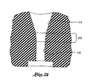
Figure 2A is a cross-sectional view showing a chamfer-type transition between adjoining sections of the improved venturi apparatus. -
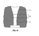
Figure 3 is a cross-sectional view illustrating the intermediate passageway and passageways fluidly coupled therewith of the improved venturi apparatus of the present invention for facilitating the mixture between a first fluid and a second fluid. - The detailed description set forth below is intended as a description of the presently preferred embodiment of the invention, and is not intended to represent the only form in which the present invention may be constructed or utilized. The description sets forth the functions and sequences of steps for constructing and operating the invention. It is to be understood, however, that the same or equivalent functions and sequences may be accomplished by different embodiments and that they are also intended to be encompassed within the scope of the invention.
- Referring now to the figures, and initially to
Figure 1 , there is perspectively illustrated an improvedventuri apparatus 10 that is operative to facilitate the assimilation and mixture of two or more fluids in a manner that is exceptionally more effective and efficient than prior art methods. At the outset, it should be understood that the term "fluid" as used herein can comprise any fluid-type substance and should be deemed to expressly encompass any type of liquid or gas, as well as materials caused to assume either a liquid or gaseous state as may be caused by the application of either heat and/or pressure, and thus may encompass condensates and vaporized or melted materials. Accordingly, fluids as used herein should be construed as broadly as possible. - The improved
venturi apparatus 10 preferably comprises a plurality of sections, namely, afirst funnel section 14, firstcylindrical section 16,intermediate passageway 18, at least one and preferably twosidearm passageways cylindrical section 28 andsecond funnel section 30, all of which are discussed more fully below, that collectively define a sequential path or passageway through which at lease one first fluid is caused to flow through and by which at least one second fluid, via its introduction throughpassageways intermediate passageway 18 and thereafter combine and exit the apparatus via secondcylindrical section 28 andsecond funnel section 30, the latter being operative to facilitate mixing and attaining the desired homogeneity. - To achieve the desired effects herein described, there is shown in
Figure 2 the arrangement of the various sections of the improved venturi apparatus used in the method of the present invention. As illustrated,first funnel section 14 defines an opening for receiving a first fluid. As will be understood by those skilled in the art, the first fluid may comprise either a single fluid or a mixture of fluids. In any event, the fluid introduced intofirst section 14, per conventional venturi design, creates a narrowing of the fluid flow path, thus creating an increase in the first fluid's velocity and decrease of the first fluid's pressure. - The first fluid then passes from the
first section 14 to a first straight, cylindrical ortubular section 16 as shown. Such firstcylindrical section 16 is operative to normalize the flow of the first fluid passing from thefirst funnel section 14 and consequently reduces fluid turbulence. In order to attain optimal functioning of the improved venturi used in the method of the present invention, a chamfer or bevel should be provided at the point interconnecting adjacent sections, 14 and 16 of the improvedventuri 10, shown as 32 inFigure 2A . In this regard, it is believed that this smooth rounded transitional surface is operative to facilitate fluid flow and minimize turbulence and disruptions. To fabricate such contoured surfaces will be easily understood by those skilled in the art and that any type of material, whether it be glass, plastic and/or metal can be readily utilized to fabricate the improved venturi devices disclosed herein. - The first fluid is then sequentially introduced from first
cylindrical section 16 tointermediate passageway 18. As illustrated,intermediate passageway 18 defines a chamber having a diameter greater than that of the firstcylindrical section 16, and is provided with a floor and ceiling as well as a mid section having a diameter substantially greater than the firstcylindrical section 16 and secondcylindrical section 28. As a consequence of having a greater diameter, the first fluid passing from the firstcylindrical section 16 to theintermediate passageway 18 experiences a slight decrease in pressure, unlike conventional venturi devices. By virtue of the fluid flow into theintermediate passageway 18, a vacuum force is created that causes a second fluid to be drawn into theintermediate passageway 18 via one or bothsidearm passageways improved venturi apparatus 10 of the present invention need only be provided with one sidearm passageway to allow for the introduction of a second fluid or, alternatively, may be provided with three or more channels to enable either a greater volume of a second fluid to be drawn into theintermediate passageway 18 or, alternatively, can serve as inlets to enable a third, fourth, fifth or more fluids to be selectively introduced into theintermediate passageway 18. Accordingly, although depicted inFigure 2 as having two diametricallyopposed sidearm passageways dedicated openings - According to a preferred embodiment, at least one or all of the
sidearm passageways intermediate passageway 18 at generally the median or mid section thereof. Along these lines, and as more clearly illustrated inFigure 3 ,sidearm passageways intermediate passageway 18 at a point below the ceiling of theintermediate passageway 18, represented by "A" and a distance above the floor of theintermediate passageway 18 represented inFigure 2 by "B". In a most highly preferred embodiment, distances "A" and "B" will be equal. Currently, however, it is known that some distance must exist between the ceiling of theintermediate passageway 18 and the sidearm passageway orpassageways passageways - By so arranging the interconnection between
sidearm passageways intermediate passageway 18, the second fluid is thus drawn into and allowed to mix with the first fluid passing into theintermediate passageway 18 in a manner substantially superior to that of prior art devices. Quite unexpectedly, it is believed that by configuring theintermediate passageway 18 to have a greater diameter relative to both first and secondcylindrical sections intermediate passageway 18, a substantially greater volume of at least one second fluid is drawn in to the fluid flow that, as a consequence, produces a substantially more thorough interaction between the fluids to thus create a resultant mixture having a higher degree of homogeneity when the combined fluids pass through the improved venturi relative the mixing of fluids via conventional venturi devices. - Following the commingling of the first and second fluids in
intermediate passageway 18, the resultant combination is then caused to pass downwardly via secondcylindrical section 28 that, similar to firstcylindrical section 16, is operative to normalize fluid flow. Thereafter, the combination of fluids is caused to thoroughly intermix and exit viasecond funnel section 30 per conventional venturi devices. Along these lines, suchsecond funnel section 30 facilitates the mixture between the fluids as the same undergo a decrease in velocity and an increase in pressure. - As will further be readily appreciated by those skilled in the art, a variety of dimensions can be utilized in each of the various sections of the improved venturi apparatus for use in a given application. In one specific embodiment exceptionally effective in facilitating the aeration of wine, especially red wine, it is believed that the following dimensions are ideal: the first
cylindrical section 14 will have a conical shape of any length tapering to 4.9 mm with a sharp reduction in 1.8 mm height to 4.7 mm, known as a chamfer or bevel, shown as 32 inFigure 2A ; firstcylindrical section 16 will have a constant diameter of 4.7 mm and a height of at least 3.6 mm;intermediate passageway 18 will have a diameter of 6.3 mm and a height of approximately 5 mm; two symmetrical, diametrically opposed sidearm passageways, 24, 26 will have lengths of approximately 8.3 mm and diameters of approximately 3.2 mm and fluidly interconnecting with theintermediate passageway 18 at approximately the mid portion thereof; a secondcylindrical section 28 will have a constant diameter of 4.7 mm and a height of 6.8 mm; and secondexit funnel section 30 will have a height of approximately 64 mm tapering to an exit diameter of approximately 10.5 mm. When so constructed, the improved venturi apparatus is operative to substantially aerate wine, especially red wine, when a flow of liquid wine is merely passed through the venturi apparatus at atmospheric pressure and the consumer need only pour the wine from the bottle through a vertically oriented venturi apparatus and into a wine glass or other receptacle, such as a decanter. Such dimensions, however, are merely one example of how to construct the improved venturi apparatus invention for a specific application and by no means should be construed as any limitation thereof. - Moreover, the
improved venturi apparatus 10, as will be readily understood by those skilled in the art, may be formed as part of ahousing 12, as shown inFigure 1 , or may otherwise be incorporated as part of a fitting or incorporated as part of a tubular pipe structure. Theimproved venturi apparatus 10 is configured to assume a vertical orientation, preferably to thus enable gravitational force to cause fluid to flow sequentially through thesections improved venturi apparatus 10 may be configured to receive fluids that are pressurized. - Additional modifications and improvements of the present invention may also be apparent to those of ordinary skill in the art. Thus, the particular combination of parts and steps described and illustrated herein is intended to represent only certain embodiments of the present invention, and is not intended to serve as limitations of alternative devices and methods as defined in the claim. As should again be reemphasized, the improved venturi apparatus may be operative to be utilized as a stand alone device or otherwise incorporated as part of an integrated process and capable of widespread utilization as would be readily appreciated by one of ordinary skill.
Claims (1)
- A method for facilitating the mixture of two or more fluids using an improved venturi apparatus (10), the improved venturi apparatus (10) comprising :a. a first funnel section (14);b. a first straight tubular section (16) fluidly coupled to said first funnel section (14);c. an intermediate passageway (18) fluidly coupled to said first straight tubular section (16), said intermediate passageway (18) defining a compartment having a diameter greater than said first straight tubular section (1,6) ;d. at least one sidearm passageway (24, 26) fluidly connected to said intermediate passageway (18);e. a second cylindrical section (28) fluidly coupled with and extending from said intermediate passageway (18);f. a second funnel section (30) fluidly coupled to said second cylindrical section (28); andg. wherein said first funnel section (14), first straight tubular section (16), said intermediate passageway (18), said second cylindrical section (28) and said second funnel section (30) are operative to sequentially receive and define a fluid flow path for at least one first fluid and said at least one sidearm passageway (24, 26) is operative to introduce at least one second fluid into said intermediate passageway (18) when said at least one first fluid passes therethrough;
the method comprising: Orientating the improved venturi apparatus (10) such that said first funnel section (14), said first straight tubular section (16), said intermediate passageway (18), said second cylindrical section (28) and said second funnel section (30) have a vertical orientation ;
characterized in that said at least one first fluid comprises mine and said at least one second fluid comprises air.
Applications Claiming Priority (2)
| Application Number | Priority Date | Filing Date | Title |
|---|---|---|---|
| US11/354,490 US7614614B2 (en) | 2006-02-15 | 2006-02-15 | Venturi apparatus |
| EP07749822A EP1984103B1 (en) | 2006-02-15 | 2007-02-01 | Improved venturi apparatus |
Related Parent Applications (1)
| Application Number | Title | Priority Date | Filing Date |
|---|---|---|---|
| EP07749822.8 Division | 2007-02-01 |
Publications (2)
| Publication Number | Publication Date |
|---|---|
| EP2277618A1 EP2277618A1 (en) | 2011-01-26 |
| EP2277618B1 true EP2277618B1 (en) | 2013-07-10 |
Family
ID=38367551
Family Applications (2)
| Application Number | Title | Priority Date | Filing Date |
|---|---|---|---|
| EP07749822A Active EP1984103B1 (en) | 2006-02-15 | 2007-02-01 | Improved venturi apparatus |
| EP10012134.2A Not-in-force EP2277618B1 (en) | 2006-02-15 | 2007-02-01 | Method for mixing two or more fluids |
Family Applications Before (1)
| Application Number | Title | Priority Date | Filing Date |
|---|---|---|---|
| EP07749822A Active EP1984103B1 (en) | 2006-02-15 | 2007-02-01 | Improved venturi apparatus |
Country Status (15)
| Country | Link |
|---|---|
| US (5) | US7614614B2 (en) |
| EP (2) | EP1984103B1 (en) |
| JP (2) | JP4967102B2 (en) |
| KR (1) | KR20080108091A (en) |
| CN (2) | CN102728250A (en) |
| AT (1) | ATE552902T1 (en) |
| AU (1) | AU2007218017B2 (en) |
| BR (1) | BRPI0707917B1 (en) |
| CA (1) | CA2642346C (en) |
| DK (2) | DK1984103T3 (en) |
| ES (2) | ES2382117T3 (en) |
| HK (1) | HK1121095A1 (en) |
| MX (1) | MX2008010461A (en) |
| WO (1) | WO2007097895A2 (en) |
| ZA (1) | ZA200807014B (en) |
Families Citing this family (61)
| Publication number | Priority date | Publication date | Assignee | Title |
|---|---|---|---|---|
| US7614614B2 (en) * | 2006-02-15 | 2009-11-10 | Exica, Inc. | Venturi apparatus |
| FI121990B (en) * | 2007-12-20 | 2011-07-15 | Beneq Oy | Device for producing fogs and particles |
| US7992844B2 (en) * | 2007-12-21 | 2011-08-09 | Frank Chiorazzi | Venturi apparatus |
| FR2931837B1 (en) * | 2008-05-27 | 2011-02-11 | Dehon | VINIFICATION AID COMPOUND AND METHOD FOR INTRODUCING SULFUR DIOXIDE IN A WINE TANK. |
| KR101063511B1 (en) * | 2008-11-10 | 2011-09-07 | 박기영 | Wine decanting device |
| US20110005516A1 (en) * | 2009-07-08 | 2011-01-13 | Xiao-Dong Xiang | Solar collector |
| US20110154994A1 (en) * | 2009-09-17 | 2011-06-30 | Area 55, Inc. | Wine aerator tower |
| US8251352B2 (en) | 2010-09-08 | 2012-08-28 | Frank Chiorazzi | Venturi apparatus for pouring and aereating beverages |
| AU2010224300A1 (en) * | 2009-09-18 | 2011-04-07 | Frank Chiorazzi | Venturi apparatus for pouring and aereating beverages |
| US8692210B2 (en) | 2009-12-15 | 2014-04-08 | Peter Depew Fiset | Photonic wine processor |
| US9237767B2 (en) | 2009-12-15 | 2016-01-19 | Peter Depew Fiset | Photonic wine processor |
| US8245882B1 (en) * | 2009-12-18 | 2012-08-21 | Federighi William D | Pouring spout for aerating poured liquid |
| CN101927126B (en) * | 2010-01-07 | 2012-07-25 | 高飞 | Method for carrying out uncatalyzed direct oxidation treatment on gas containing nitric oxide by using Venturi oxidizer |
| US8999246B2 (en) * | 2010-05-25 | 2015-04-07 | Exxonmobil Research And Engineering Company | Fluid injection nozzle for fluid bed reactors |
| US8807358B2 (en) | 2010-09-29 | 2014-08-19 | Mars Aerator Llc | Within bottle aerator |
| US9033187B2 (en) | 2010-10-06 | 2015-05-19 | Aerawine Llc | Bottle top liquid aerator |
| US8707828B2 (en) | 2010-11-07 | 2014-04-29 | William P Ward | Combined corked bottle opener and fluid aerator |
| US8925443B2 (en) * | 2010-12-20 | 2015-01-06 | True Fabrications, Inc. | Variably throttled beverage aerator |
| US20120156345A1 (en) * | 2010-12-20 | 2012-06-21 | Dhruv Agarwal | Bottle top aerator |
| WO2012112774A1 (en) * | 2011-02-16 | 2012-08-23 | Casper Thomas J | Venturi device and method |
| US9205385B2 (en) * | 2011-03-04 | 2015-12-08 | Focus Products Group International, Llc | Venturi apparatus with a fluid flow regulator valve |
| TW201242555A (en) * | 2011-04-21 | 2012-11-01 | Tian guo lin | Brewing mechanism having liquid activation function |
| KR101236216B1 (en) * | 2011-04-22 | 2013-02-22 | 한국미니맥스 주식회사 | Increasing device of dissolved oxygen and a river structure having it |
| US20130019755A1 (en) * | 2011-07-22 | 2013-01-24 | Pao-Wu Tien | Brewing device |
| US8590865B2 (en) | 2011-08-11 | 2013-11-26 | Vinomax Llc | Liquid aerator |
| US8517350B2 (en) | 2011-08-24 | 2013-08-27 | Franmara, Inc. | Venturi apparatus for pouring and aereating beverages |
| US20130056504A1 (en) | 2011-09-02 | 2013-03-07 | Ottocom, Llc | System and Method for Interfacing with, and Controlling, Beverage Dispensing Containers |
| US10870565B2 (en) | 2011-09-02 | 2020-12-22 | Bevolution Systems, Llc | Scalable modular system and method for storing, preserving, managing, and selectively dispensing beverages |
| CN102406457B (en) * | 2011-09-30 | 2014-04-30 | 广州市拓璞电器发展有限公司 | Multipurpose decanter |
| CN102349810B (en) * | 2011-10-14 | 2013-09-11 | 周培华 | Decanter |
| US8727324B2 (en) | 2011-12-02 | 2014-05-20 | Prime Wine Products Llc | Wine aerator |
| WO2013104100A1 (en) * | 2012-01-09 | 2013-07-18 | Jiang Peiqiang | Multifunctional wine decanter |
| US20130202757A1 (en) * | 2012-02-06 | 2013-08-08 | Nathaniel Hawkins | Apparatus for aerating and filtering wine |
| USD778667S1 (en) * | 2012-02-16 | 2017-02-14 | Thomas J Casper | Venturi device |
| USD740062S1 (en) * | 2012-03-12 | 2015-10-06 | Dillon Burroughs | Martini bottle |
| CN102876531A (en) * | 2012-03-24 | 2013-01-16 | 雷鉴源 | Ultra high pressure (UHP) wine |
| US20130255505A1 (en) * | 2012-03-29 | 2013-10-03 | James M. Verbicky | Venturi-Type Wine Aerator With Adjustable Aeration |
| KR101318777B1 (en) * | 2012-03-30 | 2013-10-16 | 주식회사 이코피앤티 | Decanter Apparatus for Wine |
| CN103372382B (en) * | 2012-04-23 | 2016-03-30 | 华东理工大学 | A kind of preparation facilities of therapeutic type micro air bubble ultrasonic contrast medium and method |
| WO2013166181A2 (en) | 2012-05-02 | 2013-11-07 | Connors Robert W | Gas diffusion apparatus for liquid aeration and carbonated liquids |
| US9120065B2 (en) | 2012-05-10 | 2015-09-01 | Shelley A. Santrach | Integrated container and aerator device |
| USD732890S1 (en) | 2012-11-27 | 2015-06-30 | Robert W. Connors | Gas diffusion apparatus |
| US9463511B2 (en) * | 2012-12-28 | 2016-10-11 | Heat Design Equipment Inc. | Inspirator for a gas heater |
| US10252304B2 (en) * | 2013-06-20 | 2019-04-09 | En Rx Chemical, Inc. | Soil and water contamination remediation injector and method of use |
| FR3007999B1 (en) | 2013-07-03 | 2015-07-17 | 10 Vins | PROCESS AND INSTALLATION FOR THE PREPARATION FOR THE TASTING OF BEVERAGE, IN PARTICULAR WINE |
| CN105722966A (en) | 2013-10-02 | 2016-06-29 | J·R·科耐基 | Method for the selective removal of sulfites from beverages and modular apparatus for same |
| AU2015218607B2 (en) * | 2014-02-24 | 2019-07-11 | Versabev, Inc. | Scalable modular system and method for storing, preserving, managing, and selectively dispensing beverages |
| CN106491006B (en) * | 2014-03-25 | 2019-04-19 | 周午贤 | A method of shortening grape wine and sobers up the time |
| EP3229948A4 (en) * | 2014-12-10 | 2018-08-08 | Robert Kremer | Multiphase device and system for heating, condensing, mixing, deaerating and pumping |
| US9795934B2 (en) | 2015-01-12 | 2017-10-24 | Robert W. Connors | Wine and spirits aerator |
| ES1138833Y (en) * | 2015-02-02 | 2015-07-28 | Prior Joaquin Escudero | Spacer cap |
| CN104549057A (en) * | 2015-02-05 | 2015-04-29 | 青岛亿明翔精细化工科技有限公司 | Multipurpose tubular packed reactor |
| WO2016149630A1 (en) | 2015-03-19 | 2016-09-22 | Sulfighter, Llc | Assembly for selectively aerating a beverage |
| ITUB20152254A1 (en) * | 2015-07-16 | 2017-01-16 | Unicredit Bank Ag Filiale Di Milano | Aerator and aerator container assembly. |
| US10246359B2 (en) | 2016-05-16 | 2019-04-02 | New Environmental Engineering, Inc. | System and method for treating wastewater |
| US10744468B2 (en) | 2016-08-18 | 2020-08-18 | Praxair Technology, Inc. | System and method for feeding gas into liquid |
| US11099584B2 (en) | 2017-03-27 | 2021-08-24 | Saudi Arabian Oil Company | Method and apparatus for stabilizing gas/liquid flow in a vertical conduit |
| USD815479S1 (en) | 2017-03-31 | 2018-04-17 | Vetesco, LLC | Wine straw |
| US10611966B2 (en) * | 2017-06-21 | 2020-04-07 | Duke Technologies, Llc | Pyrolysis reactor system and method |
| DE102017116394A1 (en) * | 2017-07-20 | 2019-01-24 | B. Braun Avitum Ag | Disposal container for used dialysis fluid and extracorporeal blood purification system with such a disposal container |
| USD855392S1 (en) * | 2018-04-10 | 2019-08-06 | Greenfield World Trade, Inc. | Wine aerator |
Family Cites Families (48)
| Publication number | Priority date | Publication date | Assignee | Title |
|---|---|---|---|---|
| US2130577A (en) | 1936-06-13 | 1938-09-20 | Eric W Bacharach | Aerating apparatus |
| GB858654A (en) * | 1956-02-28 | 1961-01-11 | Rogor Strange Waddington | Apparatus for mixing liquids |
| US3704008A (en) * | 1970-04-13 | 1972-11-28 | Charles Thomas Ziegler | Vacuum producing means and method |
| US3774645A (en) | 1971-12-06 | 1973-11-27 | Universal Oil Prod Co | Flange-free venturi nozzle insert |
| US4205710A (en) | 1974-06-28 | 1980-06-03 | Dunicz Boleslaw L | Funnel device for safe disposal of chemical wastes |
| JPS51134388A (en) * | 1975-05-19 | 1976-11-20 | Mitsubishi Precision Co Ltd | Process for producing emulsion |
| US4308138A (en) * | 1978-07-10 | 1981-12-29 | Woltman Robert B | Treating means for bodies of water |
| US4564480A (en) * | 1978-12-20 | 1986-01-14 | Eduard Kamelmacher | Aeration system and method |
| DE2907694C2 (en) | 1979-02-27 | 1984-11-22 | Mannesmann AG, 4000 Düsseldorf | Mixing device for flowing liquid, gaseous or vaporous media |
| JPS5617625A (en) * | 1979-07-25 | 1981-02-19 | Susumu Hashimoto | Contacting and mixing apparatus for gas and liquid |
| EP0211834B1 (en) * | 1984-04-03 | 1988-12-28 | Feldmühle Aktiengesellschaft | Aeration installation |
| US4595121A (en) | 1984-09-10 | 1986-06-17 | Sheldon Schultz | Apparatus and method for dispensing and preserving bottled degradable liquids such as wine and the like |
| ES8700918A1 (en) | 1985-01-31 | 1986-11-16 | Spidem Srl | An emulsifier unit particularly for emulsifying steam and milk to prepare cappuccino's and the like beverages. |
| US4640782A (en) * | 1985-03-13 | 1987-02-03 | Ozo-Tek, Inc. | Method and apparatus for the generation and utilization of ozone and singlet oxygen |
| DE68908275T2 (en) | 1988-06-01 | 1994-01-20 | Lucio Grossi | Device for frothing and heating milk for beverages. |
| JPH0448920A (en) * | 1990-06-18 | 1992-02-18 | Inax Corp | Ejector and purifying apparatus |
| US5207148A (en) | 1990-06-25 | 1993-05-04 | Caffe Acorto, Inc. | Automated milk inclusive coffee apparatus |
| JP2540072Y2 (en) * | 1991-02-20 | 1997-07-02 | エムケー精工株式会社 | Liquid mixing equipment |
| AU648910B2 (en) | 1991-06-13 | 1994-05-05 | Alun Frederich Bartsch | Wine breather |
| JPH0523687A (en) * | 1991-07-18 | 1993-02-02 | Inax Corp | Sewage treating device |
| WO1993023340A1 (en) | 1992-05-14 | 1993-11-25 | Idec Izumi Corporation | Method and apparatus for dissolving a gas into and mixing the same with a liquid |
| US5459896A (en) | 1992-06-24 | 1995-10-24 | Span-America Medical Systems, Inc. | Wheelchair cushion and cover |
| DE4220986A1 (en) | 1992-06-26 | 1994-01-05 | Gotthard Dipl Ing Mahlich | Device for preparing milk foam for cappuccino |
| IT1263761B (en) * | 1993-01-19 | 1996-08-29 | DEVICE FOR THE PRODUCTION OF FOAMING STEAM, ESPECIALLY FOR EQUIPMENT FOR THE PRODUCTION OF HOT DRINKS | |
| US5403475A (en) * | 1993-01-22 | 1995-04-04 | Allen; Judith L. | Liquid decontamination method |
| US6162021A (en) * | 1993-09-06 | 2000-12-19 | B.H.R. Group Limited | System for pumping liquids using a jet pump and a phase separator |
| JP3058595B2 (en) | 1996-07-26 | 2000-07-04 | 徹 工藤 | Gas-liquid mixing device |
| JP3443728B2 (en) * | 1998-02-09 | 2003-09-08 | 孝 山本 | Wastewater purification equipment |
| RU2142071C1 (en) * | 1998-03-16 | 1999-11-27 | Попов Сергей Анатольевич | Multi-nozzle liquid-and-gas ejector |
| US6581856B1 (en) | 1998-11-06 | 2003-06-24 | Bowles Fluidics Corporation | Fluid mixer |
| US6568660B1 (en) | 1999-03-24 | 2003-05-27 | Torben Flanbaum | Pourer for simultaneously pouring liquid from a container and mixing air into the liquid |
| IT1306856B1 (en) * | 1999-06-07 | 2001-10-11 | Ct Sviluppo Materiali Spa | DEVICE FOR SOLUBILIZING AN AERIFORM IN FLUID, AND USE OF A DEVICE. |
| EP1242769B1 (en) * | 1999-12-23 | 2010-12-15 | Venturie AS | Method, apparatus and system for the condensation of vapours and gases |
| US6623154B1 (en) | 2000-04-12 | 2003-09-23 | Premier Wastewater International, Inc. | Differential injector |
| US6588463B2 (en) | 2000-07-24 | 2003-07-08 | Dana Swan | Drip catcher system |
| DE20102048U1 (en) * | 2001-02-06 | 2002-01-10 | Eugster Frismag Ag Romanshorn | Safety device of a steam foaming device for producing a foamed beverage |
| GB0113735D0 (en) * | 2001-06-05 | 2001-07-25 | Holset Engineering Co | Mixing fluid streams |
| JP2003126667A (en) * | 2001-10-22 | 2003-05-07 | Mitsuru Kitahara | Air mixing and feeding device |
| US7150586B2 (en) | 2002-08-16 | 2006-12-19 | Therma Corporation, Inc. | Wine must and pomace pump |
| WO2004022208A1 (en) * | 2002-09-09 | 2004-03-18 | Japan Institute Of Foods Ecology,Inc. | Device for liquid dilution and mixing |
| JP2004097550A (en) * | 2002-09-10 | 2004-04-02 | Sumitomo Rubber Ind Ltd | Golf club head and manufacturing method therefor |
| JP2004122043A (en) | 2002-10-04 | 2004-04-22 | Okumine:Kk | Apparatus for manufacturing ozone water |
| US6986506B2 (en) * | 2003-05-01 | 2006-01-17 | Chapman Teddie C | Water aerator and method of using same |
| US20040251566A1 (en) * | 2003-06-13 | 2004-12-16 | Kozyuk Oleg V. | Device and method for generating microbubbles in a liquid using hydrodynamic cavitation |
| JP2006061829A (en) * | 2004-08-26 | 2006-03-09 | Koji Ejima | Micro air-bubble generation apparatus, dissolved oxygen remover using the same and dissolved oxygen removing method using them |
| US7614614B2 (en) * | 2006-02-15 | 2009-11-10 | Exica, Inc. | Venturi apparatus |
| US7992844B2 (en) * | 2007-12-21 | 2011-08-09 | Frank Chiorazzi | Venturi apparatus |
| US20100122919A1 (en) * | 2008-11-18 | 2010-05-20 | Burroughs James R | Beverage glass with internal decanting, filtering,mixing and aerating cell |
-
2006
- 2006-02-15 US US11/354,490 patent/US7614614B2/en active Active
-
2007
- 2007-02-01 ES ES07749822T patent/ES2382117T3/en active Active
- 2007-02-01 MX MX2008010461A patent/MX2008010461A/en active IP Right Grant
- 2007-02-01 KR KR1020087021251A patent/KR20080108091A/en not_active Application Discontinuation
- 2007-02-01 CN CN2011103961420A patent/CN102728250A/en active Pending
- 2007-02-01 JP JP2008555260A patent/JP4967102B2/en not_active Expired - Fee Related
- 2007-02-01 WO PCT/US2007/002893 patent/WO2007097895A2/en active Application Filing
- 2007-02-01 BR BRPI0707917-6A patent/BRPI0707917B1/en not_active IP Right Cessation
- 2007-02-01 ES ES10012134T patent/ES2423996T3/en active Active
- 2007-02-01 AT AT07749822T patent/ATE552902T1/en active
- 2007-02-01 DK DK07749822.8T patent/DK1984103T3/en active
- 2007-02-01 CA CA2642346A patent/CA2642346C/en active Active
- 2007-02-01 EP EP07749822A patent/EP1984103B1/en active Active
- 2007-02-01 CN CN2007800125202A patent/CN101437604B/en active Active
- 2007-02-01 AU AU2007218017A patent/AU2007218017B2/en not_active Ceased
- 2007-02-01 EP EP10012134.2A patent/EP2277618B1/en not_active Not-in-force
- 2007-02-01 DK DK10012134.2T patent/DK2277618T3/en active
-
2008
- 2008-08-14 ZA ZA200807014A patent/ZA200807014B/en unknown
-
2009
- 2009-02-02 HK HK09100917.1A patent/HK1121095A1/en not_active IP Right Cessation
- 2009-09-30 US US12/571,087 patent/US7841584B2/en active Active
-
2010
- 2010-11-04 US US12/939,952 patent/US8505883B2/en active Active
-
2011
- 2011-07-25 JP JP2011162395A patent/JP5101721B2/en not_active Expired - Fee Related
-
2012
- 2012-07-19 US US13/553,492 patent/US8733742B2/en active Active
-
2014
- 2014-04-24 US US14/261,267 patent/US20140232020A1/en not_active Abandoned
Also Published As
Similar Documents
| Publication | Publication Date | Title |
|---|---|---|
| EP2277618B1 (en) | Method for mixing two or more fluids | |
| US8251352B2 (en) | Venturi apparatus for pouring and aereating beverages | |
| AU2011203112B2 (en) | Improved venturi apparatus | |
| EP1789169B1 (en) | Device for mixing fluids | |
| AU2013100256A4 (en) | Method of Aerating Wine | |
| CA2714931C (en) | Venturi apparatus for pouring and aereating beverages | |
| CN113856504B (en) | Sanitary gas-liquid mixing device |
Legal Events
| Date | Code | Title | Description |
|---|---|---|---|
| PUAI | Public reference made under article 153(3) epc to a published international application that has entered the european phase |
Free format text: ORIGINAL CODE: 0009012 |
|
| AC | Divisional application: reference to earlier application |
Ref document number: 1984103 Country of ref document: EP Kind code of ref document: P |
|
| AK | Designated contracting states |
Kind code of ref document: A1 Designated state(s): AT BE BG CH CY CZ DE DK EE ES FI FR GB GR HU IE IS IT LI LT LU LV MC NL PL PT RO SE SI SK TR |
|
| AX | Request for extension of the european patent |
Extension state: AL BA HR MK RS |
|
| 17P | Request for examination filed |
Effective date: 20110726 |
|
| 17Q | First examination report despatched |
Effective date: 20111221 |
|
| RAP1 | Party data changed (applicant data changed or rights of an application transferred) |
Owner name: VINTURI, INC. |
|
| TPAC | Observations filed by third parties |
Free format text: ORIGINAL CODE: EPIDOSNTIPA |
|
| GRAP | Despatch of communication of intention to grant a patent |
Free format text: ORIGINAL CODE: EPIDOSNIGR1 |
|
| GRAS | Grant fee paid |
Free format text: ORIGINAL CODE: EPIDOSNIGR3 |
|
| GRAA | (expected) grant |
Free format text: ORIGINAL CODE: 0009210 |
|
| AC | Divisional application: reference to earlier application |
Ref document number: 1984103 Country of ref document: EP Kind code of ref document: P |
|
| AK | Designated contracting states |
Kind code of ref document: B1 Designated state(s): AT BE BG CH CY CZ DE DK EE ES FI FR GB GR HU IE IS IT LI LT LU LV MC NL PL PT RO SE SI SK TR |
|
| REG | Reference to a national code |
Ref country code: GB Ref legal event code: FG4D |
|
| REG | Reference to a national code |
Ref country code: CH Ref legal event code: EP Ref country code: AT Ref legal event code: REF Ref document number: 620602 Country of ref document: AT Kind code of ref document: T Effective date: 20130715 |
|
| REG | Reference to a national code |
Ref country code: DK Ref legal event code: T3 |
|
| REG | Reference to a national code |
Ref country code: IE Ref legal event code: FG4D |
|
| REG | Reference to a national code |
Ref country code: DE Ref legal event code: R096 Ref document number: 602007031621 Country of ref document: DE Effective date: 20130905 |
|
| REG | Reference to a national code |
Ref country code: ES Ref legal event code: FG2A Ref document number: 2423996 Country of ref document: ES Kind code of ref document: T3 Effective date: 20130926 |
|
| REG | Reference to a national code |
Ref country code: SE Ref legal event code: TRGR |
|
| PG25 | Lapsed in a contracting state [announced via postgrant information from national office to epo] |
Ref country code: SI Free format text: LAPSE BECAUSE OF FAILURE TO SUBMIT A TRANSLATION OF THE DESCRIPTION OR TO PAY THE FEE WITHIN THE PRESCRIBED TIME-LIMIT Effective date: 20130710 |
|
| REG | Reference to a national code |
Ref country code: AT Ref legal event code: MK05 Ref document number: 620602 Country of ref document: AT Kind code of ref document: T Effective date: 20130710 |
|
| REG | Reference to a national code |
Ref country code: NL Ref legal event code: VDEP Effective date: 20130710 |
|
| REG | Reference to a national code |
Ref country code: LT Ref legal event code: MG4D |
|
| PG25 | Lapsed in a contracting state [announced via postgrant information from national office to epo] |
Ref country code: AT Free format text: LAPSE BECAUSE OF FAILURE TO SUBMIT A TRANSLATION OF THE DESCRIPTION OR TO PAY THE FEE WITHIN THE PRESCRIBED TIME-LIMIT Effective date: 20130710 Ref country code: IS Free format text: LAPSE BECAUSE OF FAILURE TO SUBMIT A TRANSLATION OF THE DESCRIPTION OR TO PAY THE FEE WITHIN THE PRESCRIBED TIME-LIMIT Effective date: 20131110 Ref country code: LT Free format text: LAPSE BECAUSE OF FAILURE TO SUBMIT A TRANSLATION OF THE DESCRIPTION OR TO PAY THE FEE WITHIN THE PRESCRIBED TIME-LIMIT Effective date: 20130710 Ref country code: CY Free format text: LAPSE BECAUSE OF FAILURE TO SUBMIT A TRANSLATION OF THE DESCRIPTION OR TO PAY THE FEE WITHIN THE PRESCRIBED TIME-LIMIT Effective date: 20130918 Ref country code: BE Free format text: LAPSE BECAUSE OF FAILURE TO SUBMIT A TRANSLATION OF THE DESCRIPTION OR TO PAY THE FEE WITHIN THE PRESCRIBED TIME-LIMIT Effective date: 20130710 Ref country code: PT Free format text: LAPSE BECAUSE OF FAILURE TO SUBMIT A TRANSLATION OF THE DESCRIPTION OR TO PAY THE FEE WITHIN THE PRESCRIBED TIME-LIMIT Effective date: 20131111 |
|
| PG25 | Lapsed in a contracting state [announced via postgrant information from national office to epo] |
Ref country code: FI Free format text: LAPSE BECAUSE OF FAILURE TO SUBMIT A TRANSLATION OF THE DESCRIPTION OR TO PAY THE FEE WITHIN THE PRESCRIBED TIME-LIMIT Effective date: 20130710 Ref country code: GR Free format text: LAPSE BECAUSE OF FAILURE TO SUBMIT A TRANSLATION OF THE DESCRIPTION OR TO PAY THE FEE WITHIN THE PRESCRIBED TIME-LIMIT Effective date: 20131011 Ref country code: LV Free format text: LAPSE BECAUSE OF FAILURE TO SUBMIT A TRANSLATION OF THE DESCRIPTION OR TO PAY THE FEE WITHIN THE PRESCRIBED TIME-LIMIT Effective date: 20130710 Ref country code: PL Free format text: LAPSE BECAUSE OF FAILURE TO SUBMIT A TRANSLATION OF THE DESCRIPTION OR TO PAY THE FEE WITHIN THE PRESCRIBED TIME-LIMIT Effective date: 20130710 Ref country code: NL Free format text: LAPSE BECAUSE OF FAILURE TO SUBMIT A TRANSLATION OF THE DESCRIPTION OR TO PAY THE FEE WITHIN THE PRESCRIBED TIME-LIMIT Effective date: 20130710 |
|
| PG25 | Lapsed in a contracting state [announced via postgrant information from national office to epo] |
Ref country code: CY Free format text: LAPSE BECAUSE OF FAILURE TO SUBMIT A TRANSLATION OF THE DESCRIPTION OR TO PAY THE FEE WITHIN THE PRESCRIBED TIME-LIMIT Effective date: 20130710 |
|
| PG25 | Lapsed in a contracting state [announced via postgrant information from national office to epo] |
Ref country code: CZ Free format text: LAPSE BECAUSE OF FAILURE TO SUBMIT A TRANSLATION OF THE DESCRIPTION OR TO PAY THE FEE WITHIN THE PRESCRIBED TIME-LIMIT Effective date: 20130710 Ref country code: EE Free format text: LAPSE BECAUSE OF FAILURE TO SUBMIT A TRANSLATION OF THE DESCRIPTION OR TO PAY THE FEE WITHIN THE PRESCRIBED TIME-LIMIT Effective date: 20130710 Ref country code: RO Free format text: LAPSE BECAUSE OF FAILURE TO SUBMIT A TRANSLATION OF THE DESCRIPTION OR TO PAY THE FEE WITHIN THE PRESCRIBED TIME-LIMIT Effective date: 20130710 Ref country code: SK Free format text: LAPSE BECAUSE OF FAILURE TO SUBMIT A TRANSLATION OF THE DESCRIPTION OR TO PAY THE FEE WITHIN THE PRESCRIBED TIME-LIMIT Effective date: 20130710 |
|
| PGFP | Annual fee paid to national office [announced via postgrant information from national office to epo] |
Ref country code: DK Payment date: 20140225 Year of fee payment: 8 Ref country code: IE Payment date: 20140218 Year of fee payment: 8 Ref country code: SE Payment date: 20140224 Year of fee payment: 8 Ref country code: DE Payment date: 20140220 Year of fee payment: 8 |
|
| PLBE | No opposition filed within time limit |
Free format text: ORIGINAL CODE: 0009261 |
|
| STAA | Information on the status of an ep patent application or granted ep patent |
Free format text: STATUS: NO OPPOSITION FILED WITHIN TIME LIMIT |
|
| PGFP | Annual fee paid to national office [announced via postgrant information from national office to epo] |
Ref country code: FR Payment date: 20140228 Year of fee payment: 8 Ref country code: IT Payment date: 20140224 Year of fee payment: 8 Ref country code: ES Payment date: 20140224 Year of fee payment: 8 |
|
| 26N | No opposition filed |
Effective date: 20140411 |
|
| PGFP | Annual fee paid to national office [announced via postgrant information from national office to epo] |
Ref country code: GB Payment date: 20140220 Year of fee payment: 8 |
|
| REG | Reference to a national code |
Ref country code: DE Ref legal event code: R097 Ref document number: 602007031621 Country of ref document: DE Effective date: 20140411 |
|
| PG25 | Lapsed in a contracting state [announced via postgrant information from national office to epo] |
Ref country code: LU Free format text: LAPSE BECAUSE OF FAILURE TO SUBMIT A TRANSLATION OF THE DESCRIPTION OR TO PAY THE FEE WITHIN THE PRESCRIBED TIME-LIMIT Effective date: 20140201 Ref country code: MC Free format text: LAPSE BECAUSE OF FAILURE TO SUBMIT A TRANSLATION OF THE DESCRIPTION OR TO PAY THE FEE WITHIN THE PRESCRIBED TIME-LIMIT Effective date: 20130710 |
|
| REG | Reference to a national code |
Ref country code: CH Ref legal event code: PL |
|
| PG25 | Lapsed in a contracting state [announced via postgrant information from national office to epo] |
Ref country code: LI Free format text: LAPSE BECAUSE OF NON-PAYMENT OF DUE FEES Effective date: 20140228 Ref country code: CH Free format text: LAPSE BECAUSE OF NON-PAYMENT OF DUE FEES Effective date: 20140228 |
|
| REG | Reference to a national code |
Ref country code: DE Ref legal event code: R119 Ref document number: 602007031621 Country of ref document: DE |
|
| REG | Reference to a national code |
Ref country code: DK Ref legal event code: EBP Effective date: 20150228 |
|
| REG | Reference to a national code |
Ref country code: SE Ref legal event code: EUG |
|
| GBPC | Gb: european patent ceased through non-payment of renewal fee |
Effective date: 20150201 |
|
| REG | Reference to a national code |
Ref country code: IE Ref legal event code: MM4A |
|
| REG | Reference to a national code |
Ref country code: FR Ref legal event code: ST Effective date: 20151030 |
|
| PG25 | Lapsed in a contracting state [announced via postgrant information from national office to epo] |
Ref country code: SE Free format text: LAPSE BECAUSE OF NON-PAYMENT OF DUE FEES Effective date: 20150202 |
|
| PG25 | Lapsed in a contracting state [announced via postgrant information from national office to epo] |
Ref country code: IT Free format text: LAPSE BECAUSE OF NON-PAYMENT OF DUE FEES Effective date: 20150201 |
|
| PG25 | Lapsed in a contracting state [announced via postgrant information from national office to epo] |
Ref country code: DE Free format text: LAPSE BECAUSE OF NON-PAYMENT OF DUE FEES Effective date: 20150901 Ref country code: DK Free format text: LAPSE BECAUSE OF NON-PAYMENT OF DUE FEES Effective date: 20150228 Ref country code: IE Free format text: LAPSE BECAUSE OF NON-PAYMENT OF DUE FEES Effective date: 20150201 Ref country code: GB Free format text: LAPSE BECAUSE OF NON-PAYMENT OF DUE FEES Effective date: 20150201 |
|
| PG25 | Lapsed in a contracting state [announced via postgrant information from national office to epo] |
Ref country code: FR Free format text: LAPSE BECAUSE OF NON-PAYMENT OF DUE FEES Effective date: 20150302 |
|
| PG25 | Lapsed in a contracting state [announced via postgrant information from national office to epo] |
Ref country code: BG Free format text: LAPSE BECAUSE OF FAILURE TO SUBMIT A TRANSLATION OF THE DESCRIPTION OR TO PAY THE FEE WITHIN THE PRESCRIBED TIME-LIMIT Effective date: 20130710 |
|
| PG25 | Lapsed in a contracting state [announced via postgrant information from national office to epo] |
Ref country code: TR Free format text: LAPSE BECAUSE OF FAILURE TO SUBMIT A TRANSLATION OF THE DESCRIPTION OR TO PAY THE FEE WITHIN THE PRESCRIBED TIME-LIMIT Effective date: 20130710 Ref country code: HU Free format text: LAPSE BECAUSE OF FAILURE TO SUBMIT A TRANSLATION OF THE DESCRIPTION OR TO PAY THE FEE WITHIN THE PRESCRIBED TIME-LIMIT; INVALID AB INITIO Effective date: 20070201 |
|
| PG25 | Lapsed in a contracting state [announced via postgrant information from national office to epo] |
Ref country code: ES Free format text: LAPSE BECAUSE OF NON-PAYMENT OF DUE FEES Effective date: 20150202 |
|
| REG | Reference to a national code |
Ref country code: ES Ref legal event code: FD2A Effective date: 20180703 |