EP2276969B1 - Vehicle lamp - Google Patents
Vehicle lamp Download PDFInfo
- Publication number
- EP2276969B1 EP2276969B1 EP09732832.2A EP09732832A EP2276969B1 EP 2276969 B1 EP2276969 B1 EP 2276969B1 EP 09732832 A EP09732832 A EP 09732832A EP 2276969 B1 EP2276969 B1 EP 2276969B1
- Authority
- EP
- European Patent Office
- Prior art keywords
- reflector
- light
- light source
- lens
- scattering elements
- Prior art date
- Legal status (The legal status is an assumption and is not a legal conclusion. Google has not performed a legal analysis and makes no representation as to the accuracy of the status listed.)
- Active
Links
- 238000000149 argon plasma sintering Methods 0.000 claims description 47
- 230000000694 effects Effects 0.000 description 2
- 239000011521 glass Substances 0.000 description 2
- 238000011161 development Methods 0.000 description 1
- 230000018109 developmental process Effects 0.000 description 1
- 238000009434 installation Methods 0.000 description 1
- 238000004519 manufacturing process Methods 0.000 description 1
- 230000003287 optical effect Effects 0.000 description 1
Images
Classifications
-
- F—MECHANICAL ENGINEERING; LIGHTING; HEATING; WEAPONS; BLASTING
- F21—LIGHTING
- F21S—NON-PORTABLE LIGHTING DEVICES; SYSTEMS THEREOF; VEHICLE LIGHTING DEVICES SPECIALLY ADAPTED FOR VEHICLE EXTERIORS
- F21S43/00—Signalling devices specially adapted for vehicle exteriors, e.g. brake lamps, direction indicator lights or reversing lights
- F21S43/40—Signalling devices specially adapted for vehicle exteriors, e.g. brake lamps, direction indicator lights or reversing lights characterised by the combination of reflectors and refractors
-
- F—MECHANICAL ENGINEERING; LIGHTING; HEATING; WEAPONS; BLASTING
- F21—LIGHTING
- F21S—NON-PORTABLE LIGHTING DEVICES; SYSTEMS THEREOF; VEHICLE LIGHTING DEVICES SPECIALLY ADAPTED FOR VEHICLE EXTERIORS
- F21S43/00—Signalling devices specially adapted for vehicle exteriors, e.g. brake lamps, direction indicator lights or reversing lights
- F21S43/20—Signalling devices specially adapted for vehicle exteriors, e.g. brake lamps, direction indicator lights or reversing lights characterised by refractors, transparent cover plates, light guides or filters
- F21S43/26—Refractors, transparent cover plates, light guides or filters not provided in groups F21S43/235 - F21S43/255
-
- F—MECHANICAL ENGINEERING; LIGHTING; HEATING; WEAPONS; BLASTING
- F21—LIGHTING
- F21S—NON-PORTABLE LIGHTING DEVICES; SYSTEMS THEREOF; VEHICLE LIGHTING DEVICES SPECIALLY ADAPTED FOR VEHICLE EXTERIORS
- F21S43/00—Signalling devices specially adapted for vehicle exteriors, e.g. brake lamps, direction indicator lights or reversing lights
- F21S43/30—Signalling devices specially adapted for vehicle exteriors, e.g. brake lamps, direction indicator lights or reversing lights characterised by reflectors
Definitions
- the present invention relates to a lamp for a vehicle having a light source, a first reflector and at least one lens, which are arranged so that light emitted by the light source is reflected by a reflector surface of the first reflector and forms a first luminous surface of the luminaire.
- the space requirements for lighting units are very tight.
- the signal effect of a luminaire is determined by the circumferential size of the radiating surface and by the luminance.
- the vehicle lights contribute significantly to the design of the vehicle. Due to the design of the lights, the vehicle is often to be given a characteristic appearance, which is easily recognized again. Furthermore, there is the problem that the cost of producing the lights should be as low as possible.
- the vehicle lamp comprises components which in turn comprise light-emitting diodes and reflectors.
- the reflectors have a plurality of reflector surfaces, via which the light emitted by the light emitting diodes is directed in the light emission direction.
- the light of the different reflector surface is scattered on light-scattering elements.
- the luminaire according to the invention has at least one second reflector whose reflector surface is arranged separately from the reflector surface of the first reflector and which is arranged such that light emitted by the light source is reflected by the reflector surface of the second reflector and forms a second luminous surface of the luminaire, wherein the first and second luminous surfaces are discontinuous.
- the at least one lens comprises light-scattering elements.
- at least one lens or the light-scattering elements of the lens is / are arranged only in the area of the luminous surfaces of the luminaire.
- the first luminous area has a disk or rectangular shape and the second luminous area has an angular shape.
- the light emission of the one light source strikes two separate reflector surfaces, which provide two separate luminous surfaces.
- several light sources are provided.
- each luminous area is assigned at least one separate light source. Due to the structure of the lamp according to the invention costs can be saved for the production of the lamp, since only one light source is required. Furthermore, the space for the usually provided further light source can be saved. Finally, the non-contiguous luminous surfaces of the luminaire can give a characteristic signature, by means of which the vehicle can be easily recognized again.
- the light source is arranged both in the focal point of the reflector surface of the first reflector and in the focal point of the reflector surface of the second reflector.
- the focal point of a reflector surface is understood to be the location from which emitted light beams are reflected by the reflector surface such that the reflected light beams are parallel to one another.
- the light rays emitted by the light source are thus reflected in this embodiment of the luminaire according to the invention of the reflector surfaces of the two reflectors so that in each case a light beam is generated from parallel light beams. Only with the lens the parallel light rays are scattered.
- This embodiment has the advantage that the luminous surfaces have a homogeneous luminance.
- the reflector surface of the first reflector lies on a surface formed by a first paraboloid of revolution. Furthermore, the reflector surface of the second reflector lies on a surface formed by a second paraboloid of revolution.
- the light source is arranged in particular at the focal point of both paraboloid of revolution. Due to the parabolic shape of the reflector surfaces and the arrangement of the light source in the focal point of the parabolas, the light reflected from the reflector surfaces is parallel. Due to this parallelism of the reflected light, which forms the two luminous surfaces, the light intensity in the luminous surfaces is very homogeneous from all viewing angles. The illuminated areas thus appear from all angles with the same brightness.
- the two paraboloid rotors can be identical.
- the two reflector surfaces are separated from each other on the surface of a single paraboloid of revolution.
- the choice of the position and the size of the reflector surfaces on the imaginary rotation paraboloid can depend on the one hand on the space requirements and on the other hand on the shape and size of the desired luminous surfaces.
- the first and second paraboloid of revolution are different.
- the two paraboloidal paraboloids thus have different parametrizations, the focal point of both paraboloidal parabolas lying identically at the position of the light source.
- the position of the two reflector surfaces can be varied even more, so that the lamp can be better adapted to the space requirements.
- the result is staggered and separately arranged reflector surfaces that provide parallel light beams in the direction of the lens.
- the light emitted by the light source strikes the reflector surface of the first reflector directly and directly onto the reflector surface of the second reflector. There are between the light source and the reflector surfaces neither optically active elements such. As lenses, prisms or the like, still arranged transparent discs.
- the light disk comprises light-scattering elements, in particular both on the side facing the light source and on the side remote from the light source.
- the light-scattering elements extend on the side facing away from the light source in the horizontal direction.
- they are horizontally oriented sub-rollers.
- On the light source side facing preferably extend light-scattering elements in the vertical direction. Also in this case, it may be vertically oriented part rollers.
- the sub-rollers can have the shape of a circular or parabolic section or another convex curvature in cross-section on the light entrance or light exit side, which results essentially from the desired light scattering.
- the light-scattering elements on the side facing away from the light source side are preferably formed particularly distinctive. They have a different curvature than the light-scattering elements on the side facing the light source.
- the curvature of the horizontally aligned sub-rollers on the side facing away from the light source side of the lens is in particular smaller than the curvature of the vertically oriented sub-rollers on the light source side facing. This design has the consequence that the part rollers on the outside from the outside are very clearly visible.
- the light-scattering elements of the lens ensure that the parallel light coming from the reflectors onto the lens is scattered at the desired angles.
- the light-scattering elements are designed so that the contour of the lens on the externally visible side of the aesthetic requirements, i. the desired design, whereas the light scattering elements on the back, i. on the side facing the light source, the main function of the light scattering takes over. Due to the visible on the outside of the lens a certain light scattering is thus generated. However, the desired light scattering is only generated by the addition of the light-scattering elements on the side not visible from the outside.
- the lens or the light-scattering elements of the lens is arranged only in the area of the luminous surfaces of the luminaire.
- the lens can thus be two separate lenses. Furthermore, only the light-scattering elements may be provided in these areas, but the lens may be otherwise contiguous.
- the light source is shielded by a mask which prevents a direct view from the outside to the light source. In this way it is ensured that from the outside only the two illuminated areas are perceived, not the light source itself.
- this has a housing which is closed by a cover plate in the light exit direction.
- the lens is arranged in this case within the housing. It thus forms an intermediate lens.
- the lens is preferably designed in clear glass optics, i. You can see from the outside without significant interference inside the case.
- the appearance of the lamp is thus determined by the intermediate lens with the light-scattering elements on the outside both in the on state of the light source and in the off state of the light source.
- the luminous surfaces are formed, which are visible through the lens.
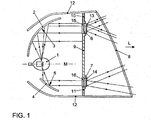
- Fig. 1 First, the basic structure of the lamp is described. In the lamp of the embodiment shown is a tail light. It should be noted that the in Fig. 1 Section shown does not necessarily take place along a plane. Rather, the cut can also be chosen so that both reflectors are visible.
- the directional information such as horizontal, vertical, and lateral, refer in the following to an installation of the lamp in a vehicle.
- the light comprises a light source 1.
- This may be a known light source 1, which is as punctiform as possible.
- a first reflector 2 with a reflector surface 3 is provided.
- the light emitted from the light source 1 hits the reflector surface 3 and is reflected there in the direction L of the fundamental light emission of the lamp.
- the reflector surface 3 lies on the surface of a first paraboloid of revolution, wherein at the focal point of this first paraboloid of revolution the light source. 1 is arranged.
- the light striking the reflector surface 3 from the light source 1 is thus reflected so that a parallel light beam results. This light beam impinges on a designed as intermediate lens 6 lens.
- the intermediate lens 6 has on the light source 1 facing Side light scattering elements 15 and on the side facing away from the light source 1, ie on the visible side from the outside, light scattering elements 13. Of these light-scattering elements 15 and 13, the light is deflected in the vertical and horizontal directions and a luminous surface 17 is formed, as will be explained later.
- the luminaire comprises a second reflector 4, the reflector surface 5 of which is arranged separately from the reflector surface 3 of the first reflector 2.
- the light emitted by the light source 1 also strikes the reflector surface 5 of the second reflector 4 and is reflected there in the direction L.
- the reflector surface 5 of the second reflector 4 lies on a surface formed by a paraboloid of revolution.
- the paraboloid of revolution of the reflector surface 5 of the second reflector 4 may be the same paraboloid of revolution on whose surface the reflector surface 3 of the first reflector 2 lies.
- the reflector surface 5 of the second reflector 4 lies on the surface of a second paraboloid of revolution, which differs from the first paraboloid of revolution.
- the focal points of the two paraboloidal rotors are each at the position of the light source 1. In the present case, both the reflector surfaces 3 and 5, and the two reflectors 2 and 4 are arranged separately from each other.
- the light emitted by the light source 1, which falls on the reflector surface 5 of the second reflector 4 is reflected by the reflector surface 5 so that there is a further parallel light beam, which falls on a second intermediate lens 7.
- the light-scattering elements 13 and 14 of the intermediate lenses 6 and 7, which are arranged on the side facing away from the light source 1 be formed identically.
- a second luminous surface 18 is formed, which is characterized in that it is not related to the first luminous surface 17, which is formed in the intermediate lens 6. There are thus created by a single light source 1 two separate luminous surfaces 17 and 18.
- the reflector surfaces 3 and 5 are not Rotationsparaboloide but so-called free-form reflector surfaces.
- the freeform reflector surfaces are adapted to the arrangement of the light source 1, that of the Freiförmreflektor vom a parallel light beam is generated. In this sense, the light source 1 is thus arranged in the focal point of the free-form reflector surfaces.
- the lamp is provided within a housing 12, which is closed by a cover plate 8 to the outside.
- the lens 8 is designed in clear glass optics, so that the rays of light emanating from the intermediate lenses 6 and 7 are essentially not influenced by the lens 8 with respect to their direction.
- the intermediate lenses 6 and 7 are arranged perpendicular to the direction L. In this plane perpendicular to the direction L is located between the two intermediate lenses 6 and 7, a mask 9, above and below the intermediate lenses 6 and 7 are also the masks 10 and 11.
- the mask 9 shields the light source 1 so that it prevents a direct view from the outside to the light source 1.
- the masks 10 and 11 also prevent that you can see from the outside laterally into the light. From the outside, therefore, only the light-scattering elements 13 and 14 of the light source 1 facing away from the sides of the intermediate lenses 6 and 7 can be seen, which form the luminous surfaces 17 and 18.
- the lamp can be completed in cross-section of the masks 9, 10 and 11 and the intermediate lenses 6 and 7.
- the masks 9 to 11, in particular the mask 9, could also be provided separately from the intermediate lenses 6 and 7.
- the intermediate lenses 6 and 7 could be formed in this case by a single intermediate lens, wherein the light-scattering elements 13 to 16 are arranged only in the region of the desired luminous surfaces 17 and 18.
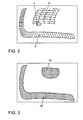
- FIGS. 2 and 3 An example of a shape of the luminous surfaces 17 and 18 and the associated reflectors 2 and 4 is in the FIGS. 2 and 3 shown.
- the reflectors 2 and 4 are arranged separately from each other, staggered.
- the shape of the reflectors 2 and 4 depends on the desired shape of the luminous surfaces 17 and 18, which in Fig. 3 is shown.
- the luminous surfaces 17 is substantially disc-shaped or rectangular and the luminous surface 18 is angular.
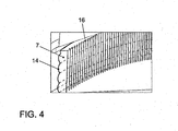
- Fig. 4 shows a detail of the intermediate lens 7.
- the intermediate lens 6 is shaped accordingly.
- the intermediate lens 7 has light-scattering elements 14 which extend in the horizontal direction. These are part rolls.
- the curvature of the surface may be circular or have another convexly curved shape.
- the parallel incident light beam becomes a vertical direction scattered.
- light-scattering elements 16 are arranged, which extend in the vertical direction. In this case too, there are partial rolls whose curvature differs from the curvature of the partial rolls of the light-scattering elements 14.
- the curvature of the light-scattering elements. 16 is larger, so that more light-scattering elements 16 are arranged on the intermediate lens 7 per unit length, as light-scattering elements 14.
- the light-scattering elements 16 cause a deflection of the parallel incident light beam in the horizontal direction. They thus essentially determine from which angles the luminaire is visible to other road users.
- aspects of the design need not be taken into account since they are essentially invisible from the outside. They can be chosen so that the optical requirements of the lamp are met.
Landscapes
- Engineering & Computer Science (AREA)
- General Engineering & Computer Science (AREA)
- Non-Portable Lighting Devices Or Systems Thereof (AREA)
Description
Die vorliegende Erfindung betrifft eine Leuchte für ein Fahrzeug mit einer Lichtquelle, einem ersten Reflektor und zumindest einer Lichtscheibe, die so angeordnet sind, dass von der Lichtquelle emittiertes Licht von einer Reflektorfläche des ersten Reflektors reflektiert wird und eine erste Leuchtfläche der Leuchte bildet.The present invention relates to a lamp for a vehicle having a light source, a first reflector and at least one lens, which are arranged so that light emitted by the light source is reflected by a reflector surface of the first reflector and forms a first luminous surface of the luminaire.
Bei der Neugestaltung von Fahrzeugen ergibt sich das Problem, dass aufgrund der gewünschten Aerodynamik und des gewünschten Designs die Bauraumverhältnisse für Beleuchtungseinheiten, insbesondere für die Leuchten einschließlich der Heckleuchten und Scheinwerfer, sehr knapp bemessen sind. Die Signalwirkung einer Leuchte wird jedoch von der Umfangsgröße der Abstrahlfläche und von der Leuchtdichte bestimmt. Des Weiteren tragen die Fahrzeugleuchten in erheblichem Maße zum Design des Fahrzeugs bei. Durch die Gestaltung der Leuchten soll dem Fahrzeug vielfach ein charakteristisches Erscheinungsbild verliehen werden, welches leicht wieder erkannt wird. Ferner ergibt sich das Problem, dass die Kosten für die Herstellung der Leuchten so gering wie möglich sein sollen.When redesigning vehicles there is the problem that due to the desired aerodynamics and the desired design, the space requirements for lighting units, especially for the lights including the rear lights and headlights, are very tight. However, the signal effect of a luminaire is determined by the circumferential size of the radiating surface and by the luminance. Furthermore, the vehicle lights contribute significantly to the design of the vehicle. Due to the design of the lights, the vehicle is often to be given a characteristic appearance, which is easily recognized again. Furthermore, there is the problem that the cost of producing the lights should be as low as possible.
In der
Es ist die Aufgabe der vorliegenden Erfindung, eine Leuchte der eingangs genannten Art bereitzustellen, die eine hohe Signalwirkung für nachfolgenden Fahrzeuge bereitstellt, kostengünstig hergestellt werden kann und dem Fahrzeug ein charakteristisches Erscheinungsbild verleiht Außerdem soll die Leuchtdichte der Leuchtflächen so homogen wie möglich sein.It is the object of the present invention to provide a luminaire of the type mentioned, which provides a high signal effect for subsequent vehicles, can be produced inexpensively and gives the vehicle a characteristic appearance addition, the luminance of the luminous surfaces should be as homogeneous as possible.
Diese Aufgabe wird erfindungsgemäß durch eine Leuchte mit den Merkmalen des Anspruchs 1 gelöst. Vorteilhafte Aus- und Weiterbildungen ergeben sich aus den Unteransprüchen.This object is achieved by a luminaire with the features of
Die erfindungsgemäße Leuchte weist zumindest einen zweiten Reflektor auf, dessen Reflektorfläche getrennt von der Reflektorfläche des ersten Reflektors angeordnet ist und der so angeordnet ist, dass von der Lichtquelle emittiertes Licht von der Reflektorfläche des zweiten Reflektors reflektiert wird und eine zweite Leuchtfläche der Leuchte bildet, wobei die erste und zweite Leuchtfläche nicht zusammenhängend sind. Die zumindest eine Lichtscheibe umfasst Licht streuende Elemente. Zudem ist/sind die zumindest eine Lichtscheibe oder die Licht streuenden Elemente der Lichtscheibe nur im Bereich der Leuchtflächen der Leuchte angeordnet. Weiterhin besitzt erfindungsgemäß die erste Leuchtfläche eine Scheiben- oder Rechteckform und die zweite Leuchtfläche eine Winkelform.The luminaire according to the invention has at least one second reflector whose reflector surface is arranged separately from the reflector surface of the first reflector and which is arranged such that light emitted by the light source is reflected by the reflector surface of the second reflector and forms a second luminous surface of the luminaire, wherein the first and second luminous surfaces are discontinuous. The at least one lens comprises light-scattering elements. In addition, at least one lens or the light-scattering elements of the lens is / are arranged only in the area of the luminous surfaces of the luminaire. Furthermore, according to the invention, the first luminous area has a disk or rectangular shape and the second luminous area has an angular shape.
Erfindungsgemäß trifft somit die Lichtemission der einen Lichtquelle auf zwei separate Reflektorflächen, welche zwei getrennte Leuchtflächen bereitstellen. Bei herkömmlichen Leuchten mit nicht zusammenhängenden Leuchtflächen sind mehrere Lichtquellen vorgesehen. Üblicherweise ist jeder Leuchtfläche zumindest eine separate Lichtquelle zugeordnet. Aufgrund des Aufbaus der erfindungsgemäßen Leuchte können für die Herstellung der Leuchte Kosten eingespart werden, da nur eine Lichtquelle erforderlich ist. Des Weiteren kann der Bauraum für die üblicherweise vorgesehene weitere Lichtquelle eingespart werden. Schließlich können die nicht zusammenhängenden Leuchtflächen der Leuchte eine charakteristische Signatur verleihen, anhand derer das Fahrzeug leicht wieder erkannt werden kann.Thus, according to the invention, the light emission of the one light source strikes two separate reflector surfaces, which provide two separate luminous surfaces. In conventional luminaires with non-contiguous luminous surfaces, several light sources are provided. Usually, each luminous area is assigned at least one separate light source. Due to the structure of the lamp according to the invention costs can be saved for the production of the lamp, since only one light source is required. Furthermore, the space for the usually provided further light source can be saved. Finally, the non-contiguous luminous surfaces of the luminaire can give a characteristic signature, by means of which the vehicle can be easily recognized again.
Gemäß einer bevorzugten Ausgestaltung der erfindungsgemäßen Leuchte ist die Lichtquelle sowohl im Brennpunkt der Reflektorfläche des ersten Reflektors als auch im Brennpunkt der Reflektorfläche des zweiten Reflektors angeordnet ist. Unter dem Brennpunkt einer Reflektorfläche wird dabei der Ort verstanden, von dem aus emittierte Lichtstrahlen so von der Reflektorfläche reflektiert werden, dass die reflektierten Lichtstrahlen parallel zueinander sind. Die von der Lichtquelle emittierten Lichtstrahlen werden somit bei dieser Ausgestaltung der erfindungsgemäßen Leuchte von den Reflektorflächen der beiden Reflektoren so reflektiert, dass jeweils ein Lichtbündel aus parallele Lichtstrahlen erzeugt wird. Erst bei der Lichtscheibe werden die parallelen Lichtstrahlen gestreut. Diese Ausgestaltung hat den Vorteil, dass die Leuchtflächen eine homogene Leuchtdichte besitzen. Es ist insbesondere nicht möglich eine Lichtquelle innerhalb einer Leuchtfläche zu identifizieren. Bei bekannten Leuchten, bei denen die Lichtemission mehrerer Lichtquellen für eine Leuchtfläche verwendet wird, hat sich nämlich ergeben, dass insbesondere aus großen Entfernungen Bereiche mit größerer Lichtintensität innerhalb einer Leuchtfläche gebildet werden. Diese Bereiche größerer Lichtintensität kann der Bertachter den einzelnen Lichtquellen zuordnen. Eine solche Identifizierung wird von der erfindungsgemäßen Leuchte vermieden.According to a preferred embodiment of the luminaire according to the invention, the light source is arranged both in the focal point of the reflector surface of the first reflector and in the focal point of the reflector surface of the second reflector. The focal point of a reflector surface is understood to be the location from which emitted light beams are reflected by the reflector surface such that the reflected light beams are parallel to one another. The light rays emitted by the light source are thus reflected in this embodiment of the luminaire according to the invention of the reflector surfaces of the two reflectors so that in each case a light beam is generated from parallel light beams. Only with the lens the parallel light rays are scattered. This embodiment has the advantage that the luminous surfaces have a homogeneous luminance. In particular, it is not possible to identify a light source within a luminous area. In known luminaires, in which the light emission of a plurality of light sources is used for a luminous area, it has been found that, in particular from long distances, areas with greater light intensity within a luminous surface are formed. These areas of greater light intensity can assign the Bertachter the individual light sources. Such identification is avoided by the luminaire according to the invention.
Gemäß einer bevorzugten Ausgestaltung der erfindungsgemäßen Leuchte liegt die Reflektorfläche des ersten Reflektors auf einer von einem ersten Rotationsparaboloid gebildeten Fläche. Ferner liegt die Reflektorfläche des zweiten Reflektors auf einer von einem zweiten Rotationsparaboloid gebildeten Fläche. Die Lichtquelle ist insbesondere im Brennpunkt beider Rotationsparaboloide angeordnet. Aufgrund der parabolischen Form der Reflektorflächen und der Anordnung der Lichtquelle im Brennpunkt der Parabeln, ist das von den Reflektorflächen reflektierte Licht parallel. Aufgrund dieser Parallelität des reflektierten Lichts, welches die beiden Leuchtflächen bildet, ist die Lichtintensität bei den Leuchtflächen aus allen Betrachtungswinkeln sehr homogen. Die Leuchtflächen erscheinen somit aus allen Winkeln mit der gleichen Helligkeit.According to a preferred embodiment of the luminaire according to the invention, the reflector surface of the first reflector lies on a surface formed by a first paraboloid of revolution. Furthermore, the reflector surface of the second reflector lies on a surface formed by a second paraboloid of revolution. The light source is arranged in particular at the focal point of both paraboloid of revolution. Due to the parabolic shape of the reflector surfaces and the arrangement of the light source in the focal point of the parabolas, the light reflected from the reflector surfaces is parallel. Due to this parallelism of the reflected light, which forms the two luminous surfaces, the light intensity in the luminous surfaces is very homogeneous from all viewing angles. The illuminated areas thus appear from all angles with the same brightness.
Die beiden Rotationsparaboloide können identisch sein. In diesem Fall liegen die beiden Reflektorflächen getrennt voneinander auf der Fläche eines einzigen Rotationsparaboloids. Die Wahl der Position und der Größe der Reflektorflächen auf dem gedachten Rotationsparaboloid kann dabei einerseits von den Bauraumverhältnissen abhängen und andererseits von der Form und Größe der gewünschten Leuchtflächen.The two paraboloid rotors can be identical. In this case, the two reflector surfaces are separated from each other on the surface of a single paraboloid of revolution. The choice of the position and the size of the reflector surfaces on the imaginary rotation paraboloid can depend on the one hand on the space requirements and on the other hand on the shape and size of the desired luminous surfaces.
Gemäß einer anderen Ausgestaltung sind der erste und der zweite Rotationsparaboloid verschieden. Die beiden Rotationsparaboloide weisen somit verschiedene Parametrisierungen auf, wobei der Brennpunkt beider Rotationsparaboloide identisch bei der Position der Lichtquelle liegt. In diesem Fall kann die Lage der beiden Reflektorflächen noch stärker variiert werden, so dass die Leuchte noch besser an die Bauraumverhältnisse angepasst werden kann. Im Ergebnis ergeben sich gestaffelt und separat voneinander angeordnete Reflektorflächen, die parallele Lichtbündel in Richtung der Lichtscheibe bereitstellen.In another embodiment, the first and second paraboloid of revolution are different. The two paraboloidal paraboloids thus have different parametrizations, the focal point of both paraboloidal parabolas lying identically at the position of the light source. In this case, the position of the two reflector surfaces can be varied even more, so that the lamp can be better adapted to the space requirements. The result is staggered and separately arranged reflector surfaces that provide parallel light beams in the direction of the lens.
Gemäß einer Ausgestaltung der erfindungsgemäßen Leuchte trifft das von der Lichtquelle emittierte Licht direkt auf die Reflektorfläche des ersten Reflektors und direkt auf die Reflektorfläche des zweiten Reflektors. Es sind zwischen der Lichtquelle und den Reflektorflächen weder optisch wirksame Elemente, wie z. B. Linsen, Prismen oder dergleichen, noch durchsichtige Scheiben angeordnet.According to one embodiment of the luminaire according to the invention, the light emitted by the light source strikes the reflector surface of the first reflector directly and directly onto the reflector surface of the second reflector. There are between the light source and the reflector surfaces neither optically active elements such. As lenses, prisms or the like, still arranged transparent discs.
Gemäß einer weiteren Ausgestaltung der erfindungsgemäßen Leuchte umfasst die Lichtscheibe insbesondere sowohl auf der der Lichtquelle zugewandten Seite als auch auf der der Lichtquelle abgewandten Seite Licht streuende Elemente. Bevorzugt erstrecken sich die Licht streuenden Elemente auf der der Lichtquelle abgewandten Seite in horizontaler Richtung. Es sind insbesondere horizontal ausgerichtete Teilwalzen. Auf der der Lichtquelle zugewandten Seite erstrecken sich bevorzugt Licht streuende Elemente in vertikaler Richtung. Auch in diesem Fall kann es sich um vertikal ausgerichtete Teilwalzen handeln. Die Teilwalzen können im Querschnitt auf der Lichteintritts- bzw. Lichtaustrittsseite die Form eines Kreis- oder Parabelabschnitts oder eine andere konvexe Krümmung haben, die sich im Wesentlichen aus der gewünschten Lichtstreuung ergibt. Die Licht streuenden Elemente auf der von der Lichtquelle abgewandten Seite sind dabei bevorzugt besonders markant ausgebildet. Sie haben eine andere Krümmung als die Licht streuenden Elemente auf der der Lichtquelle zugewandten Seite. Die Krümmung der horizontal ausgerichteten Teilwalzen auf der der Lichtquelle abgewandten Seite der Lichtscheibe ist insbesondere kleiner als die Krümmung der vertikal ausgerichteten Teilwalzen auf der der Lichtquelle zugewandten Seite. Diese Gestaltung hat zur Folge, dass die Teilwalzen auf der Außenseite von außen sehr markant sichtbar sind.In accordance with a further embodiment of the luminaire according to the invention, the light disk comprises light-scattering elements, in particular both on the side facing the light source and on the side remote from the light source. Preferably, the light-scattering elements extend on the side facing away from the light source in the horizontal direction. In particular, they are horizontally oriented sub-rollers. On the light source side facing preferably extend light-scattering elements in the vertical direction. Also in this case, it may be vertically oriented part rollers. The sub-rollers can have the shape of a circular or parabolic section or another convex curvature in cross-section on the light entrance or light exit side, which results essentially from the desired light scattering. The light-scattering elements on the side facing away from the light source side are preferably formed particularly distinctive. They have a different curvature than the light-scattering elements on the side facing the light source. The curvature of the horizontally aligned sub-rollers on the side facing away from the light source side of the lens is in particular smaller than the curvature of the vertically oriented sub-rollers on the light source side facing. This design has the consequence that the part rollers on the outside from the outside are very clearly visible.
Die Licht streuenden Elemente der Lichtscheibe sorgen dafür, dass das von den Reflektoren auf die Lichtscheibe treffende parallele Licht in die gewünschten Winkel gestreut wird. Dabei werden die Licht streuenden Elemente so gestaltet, dass die Kontur der Lichtscheibe auf der von außen sichtbaren Seite den ästhetischen Anforderungen, d.h. dem gewünschten Design, entspricht, wohingegen die Licht streuenden Elemente auf der Rückseite, d.h. auf der der Lichtquelle zugewandten Seite, die Hauptfunktion der Lichtstreuung übernimmt. Durch die auf der von außen sichtbaren Seite der Lichtscheibe wird somit eine bestimmte Lichtstreuung erzeugt. Die gewünschte Lichtstreuung wird jedoch erst durch die Ergänzung der Licht streuenden Elemente auf der von außen nicht sichtbaren Seite erzeugt.The light-scattering elements of the lens ensure that the parallel light coming from the reflectors onto the lens is scattered at the desired angles. In this case, the light-scattering elements are designed so that the contour of the lens on the externally visible side of the aesthetic requirements, i. the desired design, whereas the light scattering elements on the back, i. on the side facing the light source, the main function of the light scattering takes over. Due to the visible on the outside of the lens a certain light scattering is thus generated. However, the desired light scattering is only generated by the addition of the light-scattering elements on the side not visible from the outside.
Gemäß der erfindungsgemäßen Leuchte ist die Lichtscheibe oder sind die Licht streuenden Elemente der Lichtscheibe nur im Bereich der Leuchtflächen der Leuchte angeordnet. Bei der Lichtscheibe kann es sich somit um zwei getrennte Lichtscheiben handeln. Ferner können auch nur die Licht streuenden Elemente in diesen Bereichen vorgesehen sein, die Lichtscheibe aber ansonsten zusammenhängend sein.According to the luminaire according to the invention, the lens or the light-scattering elements of the lens is arranged only in the area of the luminous surfaces of the luminaire. The lens can thus be two separate lenses. Furthermore, only the light-scattering elements may be provided in these areas, but the lens may be otherwise contiguous.
Gemäß einer weiteren Ausgestaltung der erfindungsgemäßen Leuchte ist die Lichtquelle von einer Maske abgeschirmt, die eine direkte Sicht von außen auf die Lichtquelle verhindert. Auf diese Weise wird sichergestellt, dass man von außen nur die beiden Leuchtflächen wahrnimmt, nicht die Lichtquelle selbst.According to a further embodiment of the luminaire according to the invention, the light source is shielded by a mask which prevents a direct view from the outside to the light source. In this way it is ensured that from the outside only the two illuminated areas are perceived, not the light source itself.
Gemäß einer weiteren Ausgestaltung der erfindungsgemäßen Leuchte weist diese ein Gehäuse auf, welches von einer Abschlussscheibe in Lichtaustrittsrichtung geschlossen ist. Die Lichtscheibe ist in diesem Fall innerhalb des Gehäuses angeordnet. Sie bildet somit eine Zwischenlichtscheibe. Die Abschlussscheibe ist bevorzugt in Klarglasoptik ausgeführt, d.h. man kann von außen ohne wesentliche Beeinträchtigung ins Innere des Gehäuses hineinsehen. Das Erscheinungsbild der Leuchte wird somit von der Zwischenlichtscheibe mit den Licht streuenden Elementen auf der Außenseite sowohl im eingeschalteten Zustand der Lichtquelle als auch im ausgeschalteten Zustand der Lichtquelle bestimmt. Auf der Außenseite der Zwischenlichtscheibe werden die Leuchtflächen gebildet, welche durch die Abschlussscheibe hindurch sichtbar sind.According to a further embodiment of the luminaire according to the invention, this has a housing which is closed by a cover plate in the light exit direction. The lens is arranged in this case within the housing. It thus forms an intermediate lens. The lens is preferably designed in clear glass optics, i. You can see from the outside without significant interference inside the case. The appearance of the lamp is thus determined by the intermediate lens with the light-scattering elements on the outside both in the on state of the light source and in the off state of the light source. On the outside of the intermediate lens, the luminous surfaces are formed, which are visible through the lens.
Die Erfindung wird nun anhand eines Ausführungsbeispiels mit Bezug zu den Zeichnungen erläutert.
-
Fig. 1 zeigt schematisch einen Schnitt durch ein Ausführungsbeispiel der erfindungsgemäßen Leuchte, -
Fig. 2 zeigt eine perspektivische Ansicht der Lichtquelle und der beiden Reflektoren des Ausführungsbeispiels der erfindungsgemäßen Leuchte, -
Fig. 3 zeigt die Ansicht des Ausführungsbeispiels der erfindungsgemäßen Leuchte im eingeschalteten Zustand von außen und -
Fig. 4 zeigt ein Detail des Ausführungsbeispiels der erfindungsgemäßen Leuchte.
-
Fig. 1 schematically shows a section through an embodiment of the lamp according to the invention, -
Fig. 2 shows a perspective view of the light source and the two reflectors of the embodiment of the lamp according to the invention, -
Fig. 3 shows the view of the embodiment of the lamp according to the invention in the on state from the outside and -
Fig. 4 shows a detail of the embodiment of the lamp according to the invention.
Mit Bezug zu
Die Leuchte umfasst eine Lichtquelle 1. Hierbei kann es sich um eine an sich bekannte Lichtquelle 1 handeln, die so punktförmig wie möglich ist. Des Weiteren ist ein erster Reflektor 2 mit einer Reflektorfläche 3 vorgesehen. Wie in
Des Weiteren umfasst die Leuchte einen zweiten Reflektor 4, dessen Reflektorfläche 5 getrennt von der Reflektorfläche 3 des ersten Reflektors 2 angeordnet ist. Auch auf die Reflektorfläche 5 des zweiten Reflektors 4 trifft das von der Lichtquelle 1 emittierte Licht und wird dort in Richtung L reflektiert. Auch die Reflektorfläche 5 des zweiten Reflektors 4 liegt auf einer von einem Rotationsparaboloid gebildeten Fläche. Bei dem Rotationsparaboloid der Reflektorfläche 5 des zweiten Reflektors 4 kann es sich um denselben Rotationsparaboloid handeln, auf dessen Fläche auch die Reflektorfläche 3 des ersten Reflektors 2 liegt. Im vorliegenden Fall liegt die Reflektorfläche 5 des zweiten Reflektors 4 jedoch auf der Fläche eines zweiten Rotationsparaboloids, der sich von dem ersten Rotationsparaboloid unterscheidet. Die Brennpunkte der beiden Rotationsparaboloide liegen jedoch jeweils bei der Position der Lichtquelle 1. Im vorliegenden Fall sind sowohl die Reflektorflächen 3 und 5, als auch die beiden Reflektoren 2 und 4 getrennt voneinander angeordnet.Furthermore, the luminaire comprises a
Das von der Lichtquelle 1 emittierte Licht, welches auf die Reflektorfläche 5 des zweiten Reflektors 4 fällt, wird von der Reflektorfläche 5 so reflektiert, dass sich ein weiteres paralleles Lichtbündel ergibt, welches auf eine zweite Zwischenlichtscheibe 7 fällt. Im vorliegenden Ausführungsbeispiel weist die Zwischenlichtscheibe 7, wie die Zwischenlichtscheibe 6, auf der der Lichtquelle 1 zugewandten Seite Licht streuende Elemente 16 und auf der der Lichtquelle 1 abgewandten Seite Licht streuende Elemente 14 auf. Dabei können die Licht streuenden Elemente 13 und 14 der Zwischenlichtscheiben 6 und 7, die auf der von der Lichtquelle 1 abgewandten Seite angeordnet sind, identisch geformt sein. Von der Zwischenlichtscheibe 7 wird eine zweite Leuchtfläche 18 gebildet, die sich dadurch auszeichnet, dass sie nicht mit der ersten Leuchtfläche 17, die bei der Zwischenlichtscheibe 6 gebildet ist, zusammenhängt. Es werden somit von einer einzigen Lichtquelle 1 zwei separate Leuchtflächen 17 und 18 geschaffen.The light emitted by the
Bei einer anderen Ausgestaltung der Leuchte sind die Reflektorflächen 3 und 5 keine Rotationsparaboloide sondern sog. Freiformreflektorflächen. Die Freiformreflektorflächen sind dabei so auf die Anordnung der Lichtquelle 1 angepasst, dass von den Freiförmreflektorflächen ein paralleles Lichtbündel erzeugt wird. In diesem Sinne ist die Lichtquelle 1 somit im Brennpunkt der Freiformreflektorflächen angeordnet.In another embodiment of the lamp, the reflector surfaces 3 and 5 are not Rotationsparaboloide but so-called free-form reflector surfaces. The freeform reflector surfaces are adapted to the arrangement of the
Die Leuchte ist innerhalb eines Gehäuses 12 vorgesehen, welche von einer Abschlussscheibe 8 nach außen abgeschlossen ist. Die Abschlussscheibe 8 ist in Klarglasoptik ausgeführt, so dass die von den Zwischenlichtscheiben 6 und 7 ausgehenden Lichtstrahlen hinsichtlich ihrer Richtung im Wesentlichen nicht von der Abschlussscheibe 8 beeinflusst werden.The lamp is provided within a
Die Zwischenlichtscheiben 6 und 7 sind senkrecht zu der Richtung L angeordnet. In dieser Ebene senkrecht zu der Richtung L befindet sich zwischen den beiden Zwischenlichtscheiben 6 und 7 eine Maske 9, oberhalb und unterhalb der Zwischenlichtscheiben 6 und 7 befinden sich ferner die Masken 10 und 11. Die Maske 9 schirmt dabei die Lichtquelle 1 so ab, dass sie eine direkte Sicht von außen auf die Lichtquelle 1 verhindert. Die Masken 10 und 11 verhindern ferner, dass man von außen seitlich in die Leuchte hineinsehen kann. Von außen sind somit nur die Licht streuenden Elemente 13 und 14 der von der Lichtquelle 1 abgewandten Seiten der Zwischenlichtscheiben 6 und 7 zu sehen, welche die Leuchtflächen 17 und 18 bildern.The
Wie in
Ein Beispiel für eine Form der Leuchtflächen 17 und 18 und der dazugehörigen Reflektoren 2 und 4 ist in den
Auf der Innenseite der Zwischenlichtscheibe 7 sind Licht streuende Elemente 16 angeordnet, die sich in vertikaler Richtung erstrecken. Auch in diesem Fall handelt es sich um Teilwalzen, deren Krümmung sich jedoch von der Krümmung der Teilwalzen der Licht streuenden Elemente 14 unterscheidet. Die Krümmung der Licht streuenden Elemente. 16 ist größer, so dass pro Längeneinheit mehr Licht streuende Elemente 16 auf der Zwischenlichtscheibe 7 angeordnet sind, als Licht streuende Elemente 14. Die Licht streuenden Elemente 16 bewirken in eine Ablenkung des parallel einfallenden Lichtbündels in horizontaler Richtung. Sie bestimmen somit im Wesentlichen, aus welchen Winkeln die Leuchte von anderen Verkehrsteilnehmern sichtbar sind. Bei der Gestaltung der licht streuenden Elemente 16 müssen Aspekte des Designs nicht berücksichtigt werden, da sie im Wesentlichen von außen nicht sichtbar sind. Sie können so gewählt werden, dass die optischen Anforderungen an die Leuchte erfüllt sind.On the inside of the
- 11
- Lichtquellelight source
- 22
- erster Reflektorfirst reflector
- 33
- Reflektorflächereflector surface
- 44
- zweiter Reflektorsecond reflector
- 55
- Reflektorflächenreflector surfaces
- 66
- ZwischenlichtscheibeBetween Lens
- 77
- ZwischerttichtscheibeZwischerttichtscheibe
- 88th
- Abschlussscheibelens
- 99
- Maskemask
- 1010
- Maskemask
- 1111
- Maskemask
- 1212
- Gehäusecasing
- 1313
- Licht streuende ElementeLight scattering elements
- 1414
- Licht streuende ElementeLight scattering elements
- 1515
- Licht streuende ElementeLight scattering elements
- 1616
- Licht streuende ElementeLight scattering elements
- 1717
- Leuchtflächelight area
- 1818
- Leuchtflächelight area
Claims (12)
- Lamp for a vehicle, comprising a light source (1), a first reflector (2), at least one second reflector (4) and at least one lens (6, 7), which are arranged in such a way that light emitted by the light source (1) is reflected by a reflector surface (3) of the first reflector (2) and forms a first luminous area (17) of the lamp and light emitted by the light source (1) is reflected by the reflector surface (5) of the second reflector (4) and forms a second luminous area (18) of the lamp, wherein the reflector surface (5) of the second reflector (4) is arranged separately from the reflector surface (3) of the first reflector (2), wherein the first and the second luminous area (17, 18) are non-contiguous, the at least one lens (6, 7) comprises light-scattering elements (13 to 16) and the at least one lens (6, 7) or the light-scattering elements (13 to 16) of the lens (6, 7) is/are arranged only in the region of the luminous areas (17, 18) of the lamp, wherein the first luminous area (17) has a disc-shaped or rectangular form and characterized in that the second luminous area (18) has an angular form.
- Lamp according to Claim 1,
characterized
in that the light source (1) is arranged in the focus of the reflector surface (3) of the first reflector (2) and in the focus of the reflector surface (5) of the second reflector (4). - Lamp according to Claim 1 or 2,
characterized
in that the reflector surface (3) of the first reflector (2) lies on a surface formed by a first paraboloid of revolution and in that the reflector surface (5) of the second reflector (4) lies on a surface formed by a second paraboloid of revolution. - Lamp according to Claim 3,
characterized
in that the first and second paraboloid of revolution are identical. - Lamp according to Claim 3,
characterized
in that the first and second paraboloid of revolution are different. - Lamp according to one of the preceding claims, characterized
in that the light emitted by the light source is directly incident on the reflector surface (3) of the first reflector (2) and directly incident on the reflector surface (5) of the second reflector (4). - Lamp according to one of the preceding claims, characterized
in that the at least one lens (6, 7) comprises light-scattering elements (13 to 16) both on the side facing the light source (1) and on the side facing away from the light source (1). - Lamp according to Claim 7,
characterized
in that the light-scattering elements (13, 14) on the side facing away from the light source (1) extend in the horizontal direction. - Lamp according to Claim 8,
characterized
in that the light-scattering elements (13, 14) on the side facing away from the light source (1) are horizontally aligned partial cylinders. - Lamp according to one of Claims 7 to 9, characterized
in that the light-scattering elements (15, 16) on the side facing the light source (1) extend in the vertical direction. - Lamp according to one of the preceding claims, characterized
in that the light source (1) is shielded by a mask (9) which prevents a direct view of the light source (1) from the outside. - Lamp according to one of the preceding claims, characterized
in that the lamp has a housing (12), which is closed-off by a termination pane (8) in the light-emergence direction (L) and in that the at least one lens (6, 7) is arranged within the housing (12).
Applications Claiming Priority (2)
| Application Number | Priority Date | Filing Date | Title |
|---|---|---|---|
| DE102008019125A DE102008019125A1 (en) | 2008-04-16 | 2008-04-16 | vehicle light |
| PCT/EP2009/052406 WO2009127464A1 (en) | 2008-04-16 | 2009-02-27 | Vehicle lamp |
Publications (2)
| Publication Number | Publication Date |
|---|---|
| EP2276969A1 EP2276969A1 (en) | 2011-01-26 |
| EP2276969B1 true EP2276969B1 (en) | 2015-08-12 |
Family
ID=40524793
Family Applications (1)
| Application Number | Title | Priority Date | Filing Date |
|---|---|---|---|
| EP09732832.2A Active EP2276969B1 (en) | 2008-04-16 | 2009-02-27 | Vehicle lamp |
Country Status (5)
| Country | Link |
|---|---|
| US (1) | US8523415B2 (en) |
| EP (1) | EP2276969B1 (en) |
| CN (2) | CN102007340B (en) |
| DE (1) | DE102008019125A1 (en) |
| WO (1) | WO2009127464A1 (en) |
Families Citing this family (9)
| Publication number | Priority date | Publication date | Assignee | Title |
|---|---|---|---|---|
| DE102011110629A1 (en) * | 2011-08-18 | 2013-02-21 | Volkswagen Aktiengesellschaft | Illumination device e.g. tail light for motor car, has opaque light extraction element that is arranged between light source and optical waveguide, and light extraction element and optical waveguide that are held together by latch |
| WO2014038177A1 (en) * | 2012-09-07 | 2014-03-13 | 三菱電機株式会社 | Vehicle headlight device |
| FR3007821B1 (en) * | 2013-06-28 | 2018-04-20 | Automotive Lighting Rear Lamps France | INDIRECT LIGHTING DEVICE FOR REAR LIGHT OF MOTOR VEHICLE |
| WO2015003949A1 (en) * | 2013-07-09 | 2015-01-15 | Koninklijke Philips N.V. | Lighting device, in particular for automotive signaling with specially shaped light pattern |
| CN103994386A (en) * | 2014-05-29 | 2014-08-20 | 江苏迅驰汽车部件有限公司 | Automobile tail lamp |
| FR3022608B1 (en) * | 2014-06-19 | 2018-07-20 | Psa Automobiles Sa. | LIGHTING AND / OR SIGNALING DEVICE GENERATING A HOMOGENEOUS LIGHT ON A SCREEN |
| DE102017214346A1 (en) * | 2017-08-17 | 2019-02-21 | Volkswagen Aktiengesellschaft | Headlight for a vehicle |
| JP7023780B2 (en) * | 2018-04-19 | 2022-02-22 | スタンレー電気株式会社 | Vehicle lighting |
| DE102018112453A1 (en) * | 2018-05-24 | 2019-11-28 | HELLA GmbH & Co. KGaA | Advance light module |
Family Cites Families (14)
| Publication number | Priority date | Publication date | Assignee | Title |
|---|---|---|---|---|
| FR1418890A (en) | 1964-09-07 | 1965-11-26 | New optical device for the study and production of signaling with imposed performance and, in particular on motor vehicles | |
| DE8801514U1 (en) * | 1988-02-06 | 1988-04-07 | Häusler, Franz Ulrich, 22962 Siek | Lamp, especially vehicle lamp |
| DE4417695C2 (en) * | 1994-05-20 | 1998-01-29 | Reitter & Schefenacker Gmbh | Motor vehicle light |
| DE19519872A1 (en) * | 1995-05-31 | 1996-12-05 | Bosch Gmbh Robert | Vehicle headlamp design |
| JP3904760B2 (en) * | 1999-05-17 | 2007-04-11 | 株式会社小糸製作所 | Vehicle sign light |
| JP2002050207A (en) * | 2000-08-02 | 2002-02-15 | Koito Mfg Co Ltd | Lighting apparatus for vehicle |
| CN2471629Y (en) * | 2001-02-27 | 2002-01-16 | 张霞 | Decorative covers on rear lights of vehicle |
| EP2327925B1 (en) * | 2002-10-18 | 2012-05-23 | Ichikoh Industries, Ltd. | Vehicle lamp with light emitting diodes |
| FR2849158B1 (en) * | 2002-12-20 | 2005-12-09 | Valeo Vision | LIGHTING MODULE FOR VEHICLE PROJECTOR |
| DE10359185B4 (en) * | 2003-12-17 | 2012-05-31 | Hella Kgaa Hueck & Co. | Lamp for vehicles |
| DE102004040159A1 (en) * | 2004-08-19 | 2006-02-23 | Hella Kgaa Hueck & Co. | Lighting unit for motor vehicles |
| JP2006222029A (en) * | 2005-02-14 | 2006-08-24 | Yamaha Motor Co Ltd | Vehicular light device and vehicle provided with the same |
| DE102005050011A1 (en) * | 2005-10-11 | 2007-04-19 | Schefenacker Vision Systems Germany Gmbh | Luminaire unit, preferably tail lamp, for vehicles, preferably motor vehicles |
| CN2835796Y (en) * | 2005-10-31 | 2006-11-08 | 哈尔滨航空工业(集团)有限公司 | Reflection system of combined headlight of automobile |
-
2008
- 2008-04-16 DE DE102008019125A patent/DE102008019125A1/en active Pending
-
2009
- 2009-02-27 WO PCT/EP2009/052406 patent/WO2009127464A1/en active Application Filing
- 2009-02-27 US US12/937,805 patent/US8523415B2/en active Active
- 2009-02-27 CN CN200980113467.4A patent/CN102007340B/en active Active
- 2009-02-27 EP EP09732832.2A patent/EP2276969B1/en active Active
- 2009-02-27 CN CN201310448138.3A patent/CN103499060B/en active Active
Also Published As
| Publication number | Publication date |
|---|---|
| CN102007340B (en) | 2016-10-12 |
| CN103499060B (en) | 2017-05-31 |
| WO2009127464A1 (en) | 2009-10-22 |
| US20110103085A1 (en) | 2011-05-05 |
| US8523415B2 (en) | 2013-09-03 |
| CN102007340A (en) | 2011-04-06 |
| EP2276969A1 (en) | 2011-01-26 |
| DE102008019125A1 (en) | 2009-10-22 |
| CN103499060A (en) | 2014-01-08 |
Similar Documents
| Publication | Publication Date | Title |
|---|---|---|
| EP2276969B1 (en) | Vehicle lamp | |
| EP2401544B1 (en) | Vehicular headlight | |
| EP2688769B1 (en) | Vehicle lamp for lighting the interior of the vehicle | |
| EP2984396B1 (en) | Lamp unit comprising a shield having at least one light window | |
| DE10243590A1 (en) | LED vehicle light with uniform brightness | |
| EP2770247B1 (en) | Motor vehicle light with an homogeneously bright appearance | |
| EP1523431B1 (en) | Lights for motor vehicles | |
| DE102013226181A1 (en) | Optical element and arrangement for emitting light | |
| EP1757857A1 (en) | Vehicle lamp | |
| DE102012102732A1 (en) | Luminaire with light emission in a border area | |
| WO2020126031A1 (en) | Illumination device for a motor vehicle headlight, and motor vehicle headlight | |
| DE102018220623A1 (en) | Lamp arrangement for a vehicle | |
| DE602004005872T2 (en) | LIGHTING AND METHOD OF LIGHTING | |
| DE102010027028B4 (en) | Automotive lighting device with a reflector homogeneously distributing light | |
| DE102019123515B4 (en) | Motor vehicle headlight with two projection light modules of different focal length and equally wide illuminated light exit lenses | |
| DE102012019941A1 (en) | Light emitting device for rear light of vehicle, hast reflector that is formed as a half mirror so that mirror reflects light component of light beam emitted by light source and transmits another light component of light beam | |
| DE102013010550B4 (en) | Vehicle light for illuminating the interior of a vehicle | |
| DE102019112343A1 (en) | Motor vehicle light | |
| EP2880360B1 (en) | Led emitter | |
| EP3412963A1 (en) | Transparent component arrangement of a light module and light module comprising such a transparent component arrangement | |
| DE102016120903A1 (en) | Lighting device of a motor vehicle | |
| DE10301257B4 (en) | Luminaire with a cover with reduced reflection | |
| DE102016122188A1 (en) | Lighting device, in particular a projector system for a headlight for motor vehicles | |
| DE9113944U1 (en) | Indicator light | |
| DE20315131U1 (en) | Reflector light, e.g. floor, ceiling or wall reflector light, especially stage reflector light, has reflector surface extending over elliptical section along ellipse outside apex, adjacent to ellipse focal point at which LED is arranged |
Legal Events
| Date | Code | Title | Description |
|---|---|---|---|
| PUAI | Public reference made under article 153(3) epc to a published international application that has entered the european phase |
Free format text: ORIGINAL CODE: 0009012 |
|
| 17P | Request for examination filed |
Effective date: 20101116 |
|
| AK | Designated contracting states |
Kind code of ref document: A1 Designated state(s): AT BE BG CH CY CZ DE DK EE ES FI FR GB GR HR HU IE IS IT LI LT LU LV MC MK MT NL NO PL PT RO SE SI SK TR |
|
| AX | Request for extension of the european patent |
Extension state: AL BA RS |
|
| DAX | Request for extension of the european patent (deleted) | ||
| RAP1 | Party data changed (applicant data changed or rights of an application transferred) |
Owner name: VOLKSWAGEN AKTIENGESELLSCHAFT |
|
| 17Q | First examination report despatched |
Effective date: 20140729 |
|
| GRAP | Despatch of communication of intention to grant a patent |
Free format text: ORIGINAL CODE: EPIDOSNIGR1 |
|
| INTG | Intention to grant announced |
Effective date: 20150220 |
|
| GRAS | Grant fee paid |
Free format text: ORIGINAL CODE: EPIDOSNIGR3 |
|
| GRAA | (expected) grant |
Free format text: ORIGINAL CODE: 0009210 |
|
| AK | Designated contracting states |
Kind code of ref document: B1 Designated state(s): AT BE BG CH CY CZ DE DK EE ES FI FR GB GR HR HU IE IS IT LI LT LU LV MC MK MT NL NO PL PT RO SE SI SK TR |
|
| REG | Reference to a national code |
Ref country code: GB Ref legal event code: FG4D Free format text: NOT ENGLISH |
|
| REG | Reference to a national code |
Ref country code: CH Ref legal event code: EP |
|
| REG | Reference to a national code |
Ref country code: AT Ref legal event code: REF Ref document number: 742495 Country of ref document: AT Kind code of ref document: T Effective date: 20150815 |
|
| REG | Reference to a national code |
Ref country code: IE Ref legal event code: FG4D Free format text: LANGUAGE OF EP DOCUMENT: GERMAN |
|
| REG | Reference to a national code |
Ref country code: DE Ref legal event code: R096 Ref document number: 502009011409 Country of ref document: DE |
|
| REG | Reference to a national code |
Ref country code: LT Ref legal event code: MG4D |
|
| REG | Reference to a national code |
Ref country code: NL Ref legal event code: MP Effective date: 20150812 |
|
| PG25 | Lapsed in a contracting state [announced via postgrant information from national office to epo] |
Ref country code: FI Free format text: LAPSE BECAUSE OF FAILURE TO SUBMIT A TRANSLATION OF THE DESCRIPTION OR TO PAY THE FEE WITHIN THE PRESCRIBED TIME-LIMIT Effective date: 20150812 Ref country code: LV Free format text: LAPSE BECAUSE OF FAILURE TO SUBMIT A TRANSLATION OF THE DESCRIPTION OR TO PAY THE FEE WITHIN THE PRESCRIBED TIME-LIMIT Effective date: 20150812 Ref country code: GR Free format text: LAPSE BECAUSE OF FAILURE TO SUBMIT A TRANSLATION OF THE DESCRIPTION OR TO PAY THE FEE WITHIN THE PRESCRIBED TIME-LIMIT Effective date: 20151113 Ref country code: NO Free format text: LAPSE BECAUSE OF FAILURE TO SUBMIT A TRANSLATION OF THE DESCRIPTION OR TO PAY THE FEE WITHIN THE PRESCRIBED TIME-LIMIT Effective date: 20151112 Ref country code: LT Free format text: LAPSE BECAUSE OF FAILURE TO SUBMIT A TRANSLATION OF THE DESCRIPTION OR TO PAY THE FEE WITHIN THE PRESCRIBED TIME-LIMIT Effective date: 20150812 |
|
| PG25 | Lapsed in a contracting state [announced via postgrant information from national office to epo] |
Ref country code: PL Free format text: LAPSE BECAUSE OF FAILURE TO SUBMIT A TRANSLATION OF THE DESCRIPTION OR TO PAY THE FEE WITHIN THE PRESCRIBED TIME-LIMIT Effective date: 20150812 Ref country code: ES Free format text: LAPSE BECAUSE OF FAILURE TO SUBMIT A TRANSLATION OF THE DESCRIPTION OR TO PAY THE FEE WITHIN THE PRESCRIBED TIME-LIMIT Effective date: 20150812 Ref country code: IS Free format text: LAPSE BECAUSE OF FAILURE TO SUBMIT A TRANSLATION OF THE DESCRIPTION OR TO PAY THE FEE WITHIN THE PRESCRIBED TIME-LIMIT Effective date: 20151212 Ref country code: SE Free format text: LAPSE BECAUSE OF FAILURE TO SUBMIT A TRANSLATION OF THE DESCRIPTION OR TO PAY THE FEE WITHIN THE PRESCRIBED TIME-LIMIT Effective date: 20150812 Ref country code: PT Free format text: LAPSE BECAUSE OF FAILURE TO SUBMIT A TRANSLATION OF THE DESCRIPTION OR TO PAY THE FEE WITHIN THE PRESCRIBED TIME-LIMIT Effective date: 20151214 Ref country code: HR Free format text: LAPSE BECAUSE OF FAILURE TO SUBMIT A TRANSLATION OF THE DESCRIPTION OR TO PAY THE FEE WITHIN THE PRESCRIBED TIME-LIMIT Effective date: 20150812 |
|
| REG | Reference to a national code |
Ref country code: FR Ref legal event code: PLFP Year of fee payment: 8 |
|
| PG25 | Lapsed in a contracting state [announced via postgrant information from national office to epo] |
Ref country code: NL Free format text: LAPSE BECAUSE OF FAILURE TO SUBMIT A TRANSLATION OF THE DESCRIPTION OR TO PAY THE FEE WITHIN THE PRESCRIBED TIME-LIMIT Effective date: 20150812 |
|
| PG25 | Lapsed in a contracting state [announced via postgrant information from national office to epo] |
Ref country code: IT Free format text: LAPSE BECAUSE OF FAILURE TO SUBMIT A TRANSLATION OF THE DESCRIPTION OR TO PAY THE FEE WITHIN THE PRESCRIBED TIME-LIMIT Effective date: 20150812 Ref country code: DK Free format text: LAPSE BECAUSE OF FAILURE TO SUBMIT A TRANSLATION OF THE DESCRIPTION OR TO PAY THE FEE WITHIN THE PRESCRIBED TIME-LIMIT Effective date: 20150812 Ref country code: SK Free format text: LAPSE BECAUSE OF FAILURE TO SUBMIT A TRANSLATION OF THE DESCRIPTION OR TO PAY THE FEE WITHIN THE PRESCRIBED TIME-LIMIT Effective date: 20150812 Ref country code: EE Free format text: LAPSE BECAUSE OF FAILURE TO SUBMIT A TRANSLATION OF THE DESCRIPTION OR TO PAY THE FEE WITHIN THE PRESCRIBED TIME-LIMIT Effective date: 20150812 Ref country code: CZ Free format text: LAPSE BECAUSE OF FAILURE TO SUBMIT A TRANSLATION OF THE DESCRIPTION OR TO PAY THE FEE WITHIN THE PRESCRIBED TIME-LIMIT Effective date: 20150812 |
|
| REG | Reference to a national code |
Ref country code: DE Ref legal event code: R097 Ref document number: 502009011409 Country of ref document: DE |
|
| PG25 | Lapsed in a contracting state [announced via postgrant information from national office to epo] |
Ref country code: BE Free format text: LAPSE BECAUSE OF NON-PAYMENT OF DUE FEES Effective date: 20160229 Ref country code: RO Free format text: LAPSE BECAUSE OF FAILURE TO SUBMIT A TRANSLATION OF THE DESCRIPTION OR TO PAY THE FEE WITHIN THE PRESCRIBED TIME-LIMIT Effective date: 20150812 |
|
| PLBE | No opposition filed within time limit |
Free format text: ORIGINAL CODE: 0009261 |
|
| STAA | Information on the status of an ep patent application or granted ep patent |
Free format text: STATUS: NO OPPOSITION FILED WITHIN TIME LIMIT |
|
| 26N | No opposition filed |
Effective date: 20160513 |
|
| PG25 | Lapsed in a contracting state [announced via postgrant information from national office to epo] |
Ref country code: SI Free format text: LAPSE BECAUSE OF FAILURE TO SUBMIT A TRANSLATION OF THE DESCRIPTION OR TO PAY THE FEE WITHIN THE PRESCRIBED TIME-LIMIT Effective date: 20150812 |
|
| PG25 | Lapsed in a contracting state [announced via postgrant information from national office to epo] |
Ref country code: MC Free format text: LAPSE BECAUSE OF FAILURE TO SUBMIT A TRANSLATION OF THE DESCRIPTION OR TO PAY THE FEE WITHIN THE PRESCRIBED TIME-LIMIT Effective date: 20150812 Ref country code: LU Free format text: LAPSE BECAUSE OF FAILURE TO SUBMIT A TRANSLATION OF THE DESCRIPTION OR TO PAY THE FEE WITHIN THE PRESCRIBED TIME-LIMIT Effective date: 20160227 |
|
| REG | Reference to a national code |
Ref country code: CH Ref legal event code: PL |
|
| PG25 | Lapsed in a contracting state [announced via postgrant information from national office to epo] |
Ref country code: LI Free format text: LAPSE BECAUSE OF NON-PAYMENT OF DUE FEES Effective date: 20160229 Ref country code: CH Free format text: LAPSE BECAUSE OF NON-PAYMENT OF DUE FEES Effective date: 20160229 |
|
| REG | Reference to a national code |
Ref country code: IE Ref legal event code: MM4A |
|
| PG25 | Lapsed in a contracting state [announced via postgrant information from national office to epo] |
Ref country code: IE Free format text: LAPSE BECAUSE OF NON-PAYMENT OF DUE FEES Effective date: 20160227 |
|
| REG | Reference to a national code |
Ref country code: FR Ref legal event code: PLFP Year of fee payment: 9 |
|
| REG | Reference to a national code |
Ref country code: AT Ref legal event code: MM01 Ref document number: 742495 Country of ref document: AT Kind code of ref document: T Effective date: 20160227 |
|
| PG25 | Lapsed in a contracting state [announced via postgrant information from national office to epo] |
Ref country code: AT Free format text: LAPSE BECAUSE OF NON-PAYMENT OF DUE FEES Effective date: 20160227 |
|
| PG25 | Lapsed in a contracting state [announced via postgrant information from national office to epo] |
Ref country code: MT Free format text: LAPSE BECAUSE OF FAILURE TO SUBMIT A TRANSLATION OF THE DESCRIPTION OR TO PAY THE FEE WITHIN THE PRESCRIBED TIME-LIMIT Effective date: 20150812 |
|
| REG | Reference to a national code |
Ref country code: FR Ref legal event code: PLFP Year of fee payment: 10 |
|
| PG25 | Lapsed in a contracting state [announced via postgrant information from national office to epo] |
Ref country code: CY Free format text: LAPSE BECAUSE OF FAILURE TO SUBMIT A TRANSLATION OF THE DESCRIPTION OR TO PAY THE FEE WITHIN THE PRESCRIBED TIME-LIMIT Effective date: 20150812 Ref country code: HU Free format text: LAPSE BECAUSE OF FAILURE TO SUBMIT A TRANSLATION OF THE DESCRIPTION OR TO PAY THE FEE WITHIN THE PRESCRIBED TIME-LIMIT; INVALID AB INITIO Effective date: 20090227 |
|
| PG25 | Lapsed in a contracting state [announced via postgrant information from national office to epo] |
Ref country code: MK Free format text: LAPSE BECAUSE OF FAILURE TO SUBMIT A TRANSLATION OF THE DESCRIPTION OR TO PAY THE FEE WITHIN THE PRESCRIBED TIME-LIMIT Effective date: 20150812 Ref country code: TR Free format text: LAPSE BECAUSE OF FAILURE TO SUBMIT A TRANSLATION OF THE DESCRIPTION OR TO PAY THE FEE WITHIN THE PRESCRIBED TIME-LIMIT Effective date: 20150812 |
|
| PG25 | Lapsed in a contracting state [announced via postgrant information from national office to epo] |
Ref country code: BG Free format text: LAPSE BECAUSE OF FAILURE TO SUBMIT A TRANSLATION OF THE DESCRIPTION OR TO PAY THE FEE WITHIN THE PRESCRIBED TIME-LIMIT Effective date: 20150812 |
|
| P01 | Opt-out of the competence of the unified patent court (upc) registered |
Effective date: 20230523 |
|
| PGFP | Annual fee paid to national office [announced via postgrant information from national office to epo] |
Ref country code: DE Payment date: 20240229 Year of fee payment: 16 Ref country code: GB Payment date: 20240220 Year of fee payment: 16 |
|
| REG | Reference to a national code |
Ref country code: DE Ref legal event code: R082 Ref document number: 502009011409 Country of ref document: DE Representative=s name: MEISSNER BOLTE PATENTANWAELTE RECHTSANWAELTE P, DE |
|
| PGFP | Annual fee paid to national office [announced via postgrant information from national office to epo] |
Ref country code: FR Payment date: 20240226 Year of fee payment: 16 |