EP2276912B1 - Rotary machine - Google Patents
Rotary machine Download PDFInfo
- Publication number
- EP2276912B1 EP2276912B1 EP09728480.6A EP09728480A EP2276912B1 EP 2276912 B1 EP2276912 B1 EP 2276912B1 EP 09728480 A EP09728480 A EP 09728480A EP 2276912 B1 EP2276912 B1 EP 2276912B1
- Authority
- EP
- European Patent Office
- Prior art keywords
- casing
- coupling flange
- blade ring
- turbine
- working fluid
- Prior art date
- Legal status (The legal status is an assumption and is not a legal conclusion. Google has not performed a legal analysis and makes no representation as to the accuracy of the status listed.)
- Active
Links
Images



Classifications
-
- F—MECHANICAL ENGINEERING; LIGHTING; HEATING; WEAPONS; BLASTING
- F01—MACHINES OR ENGINES IN GENERAL; ENGINE PLANTS IN GENERAL; STEAM ENGINES
- F01D—NON-POSITIVE DISPLACEMENT MACHINES OR ENGINES, e.g. STEAM TURBINES
- F01D25/00—Component parts, details, or accessories, not provided for in, or of interest apart from, other groups
- F01D25/24—Casings; Casing parts, e.g. diaphragms, casing fastenings
- F01D25/243—Flange connections; Bolting arrangements
-
- F—MECHANICAL ENGINEERING; LIGHTING; HEATING; WEAPONS; BLASTING
- F01—MACHINES OR ENGINES IN GENERAL; ENGINE PLANTS IN GENERAL; STEAM ENGINES
- F01D—NON-POSITIVE DISPLACEMENT MACHINES OR ENGINES, e.g. STEAM TURBINES
- F01D25/00—Component parts, details, or accessories, not provided for in, or of interest apart from, other groups
- F01D25/24—Casings; Casing parts, e.g. diaphragms, casing fastenings
- F01D25/26—Double casings; Measures against temperature strain in casings
-
- F—MECHANICAL ENGINEERING; LIGHTING; HEATING; WEAPONS; BLASTING
- F05—INDEXING SCHEMES RELATING TO ENGINES OR PUMPS IN VARIOUS SUBCLASSES OF CLASSES F01-F04
- F05D—INDEXING SCHEME FOR ASPECTS RELATING TO NON-POSITIVE-DISPLACEMENT MACHINES OR ENGINES, GAS-TURBINES OR JET-PROPULSION PLANTS
- F05D2260/00—Function
- F05D2260/30—Retaining components in desired mutual position
Definitions
- the present invention relates to a rotary machine used for a steam turbine, a gas turbine, or the like.
- a casing used for a steam turbine or a gas turbine is divided into two, i.e., an upper casing and a lower casing in which a rotor shaft is incorporated, and these casings are coupled to each other on a horizontal surface using a bolt (see Patent Japanese Unexamined Utility Model Application, Publication No. S60-195908 , for example).
- the casing is integrally formed as one piece, a rotor shaft portion is inserted from one end opening of the casing, and the end opening is hermetically closed by fastening a screw ring which is engaged with a screw portion provided on an inner periphery of the casing (see Patent Japanese Unexamined Patent Application, Publication No. S59-213907 , for example).
- It is an object of the casing structure described above is to secure rigidity of the entire apparatus with respect to working fluid having high temperature and high pressure, and to prevent leak of the working fluid.
- the upper casing and the lower casing are provided on entire peripheries of the horizontal surfaces thereof with joining flanges, which project from the entire periphery of the horizontal surface of the casing and thus there is a problem that the joined casing itself is increased in size.
- the joining surface extends over the entire periphery of the horizontal surface of the casing, and thus there is a problem that a range is increased from which the working fluid leaks.
- a penetrating portion of the rotor shaft is located on the joining surface of the casing, there is a problem that the working fluid leaks easier.
- the range from which the working fluid leaks can be reduced as compared with a case where the casing is provided on the entire periphery with the joining flanges.
- the above structure in which the casing is hermetically closed can be employed only to a relatively small turbine, and such a structure must be replaced with a structure provided with flanges in a large turbine. In this case, there are problems that the flange and the joining bolt project in the axial direction, the entire length of the casing is increased, and the entire rotary machine is increased in size.
- a pressure vessel which further covers the casing is provided, a clean fluid which is not contaminated by the certain material is charged under higher pressure than the working fluid in a space between the pressure vessel and the casing, thereby preventing the fluid in the casing from leaking outside (see Fig. 5 ).
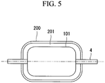
- Fig. 5 shows a configuration in which a casing 101 of the turbine body described above is accommodated in a pressure vessel (outer casing) 200. Constituent parts of the turbine are accommodated in the casing 101 (not shown).
- a rotor shaft 4 penetrates the casing 101 and the pressure vessel 200.
- a clean fluid which has pressure higher than the working fluid in the turbine and which is not contaminated by a certain material is charged in a space 201 between the casing 101 and the pressure vessel 200 so as to prevent the fluid in the casing 101 from leaking outside.
- the pressure vessel 200 is also increased in size.
- a blade ring which holds turbine stator blades is mainly supported at the end opening.
- the blade ring is supported in a cantilever manner.
- an overhang of the blade ring is made longer and thus, there are problems that a center is not sufficiently be held, and influence of a difference in thermal extension in the axial direction between a rotating portion and a stationary portion is increased.
- GB 2 024 958 A describes a rotor for a turbomachine having a turbine casing and a combustor casing being connected with each other and interposing a low pressure shroud support and a low pressure nozzle support.
- the present invention has been accomplished to solve the above problems, and it is an object of the present invention to provide a rotary machine according to claim 1 which can be reduced in size and which can enhance reliability and performance
- the present invention provides the following means.
- a casing structure of a turbine according to the present invention includes the features of claim 1.
- the casing is divided into two in the axial direction, for example on a division surface intersecting with the rotor shaft, and the casing can be reduced in size as compared with a case where the casing is divided into two on the horizontal surface, e.g., on a division surface extending along the rotor shaft.
- coupling flanges used for fastening the divided casings to each other project outward from the entire periphery of the casing.
- a cross sectional area of a casing divided into two on vertical surface perpendicular to the rotor shaft becomes smaller than a horizontal cross section of a casing divided into two on the horizontal surface. Therefore, in the casing which is divided into two (first casing and second casing) in the axial direction, the projecting range of the coupling flanges can be made smaller as compared with the casing divided into two on the horizontal surface. In this configuration, the casing can be reduced in size.
- the third coupling flange which extends from the blade ring in a direction intersecting with the axial direction, more preferably, in a substantially vertical direction, is sandwiched between the first coupling flange of the first casing and the second coupling flange of the second casing which are divided in the axial direction, in assembling the first casing, the second casing and the blade ring.
- overhang of the blade ring can be reduced.
- the overhang of the blade ring can be reduced as compared with the pot-like structure described in Japanese Unexamined Patent Application, Publication No. S59-213907 .
- holding precision of the center of the blade ring with respect to the rotor shaft is enhanced.
- thermal extension of the blade ring in the axial direction can equally be distributed.
- connection member disposed between the blade ring and the casing projects from the high-pressure side toward the low-pressure side of the working fluid.
- the joining member is a conical member which is disposed between the blade ring and the third coupling flange, and which inclines from the high-pressure side to the low-pressure side of the working fluid flowing between the rotor blade and the stator blade radially outward around the rotor shaft.
- connection member functions as an end plate of the pressure vessel, strength of the connection member is enhanced.
- the casing is divided into two in the axial direction.
- leakage of the working fluid to outside the casing and inflow of another fluid into the casing are reduced as compared with a case where the casing is divided into two on the horizontal surface. That is, there is no joining surface of the flange in the penetrating portion of the rotor shaft, leakage of the working fluid to outside the casing and inflow of another fluid into the casing are reduced.
- an outer peripheral surface of the third coupling flange sandwiched between the first and second coupling flanges of the first and second casings divided in the axial direction may be enclosed between the first and second coupling flanges.
- the first coupling flange and the second coupling flange may be directly joined to each other radially outside around the rotor shaft, and the first coupling flange and the second coupling flange may be joined radially inside with the third coupling flange sandwiched therebetween.
- a pressure vessel accommodating the casing therein is provided outside the casing, and a fluid with a pressure higher than the working fluid flowing between the rotor blades and the stator blades is filled in a space between the casing and the pressure vessel.
- the working fluid is prevented from flowing into the space between the casing and the pressure vessel by charging a fluid having pressure higher than that of the working fluid into the space. Therefore, the working fluid is prevented from flowing outside the casing.
- the casing is divided into two in the axial direction, there are effects that the casing and the pressure vessel (outer casing) enclosing the casing therein can be reduced in size, leakage of the working fluid to outside the casing and inflow of another fluid into the casing are reduced, and reliability and performance of the rotary machine are enhanced.
- a casing structure of a gas turbine and the gas turbine having such a casing structure according to an embodiment of the present invention will be described with reference to Figs. 1 to 5 .
- Fig. 1 is a schematic diagram for describing an entire configuration of the gas turbine according to a first example of the present invention.
- a gas turbine (rotary machine) 100 includes a casing 101 constituting an outer shape of the gas turbine 100, a blade ring 3 which holds turbine stator blades 10 on an inner periphery thereof, a rotor shaft 4 in which turbine rotor blades 11 are embedded, an inlet scroll portion 5 which supplies a working fluid to a first stage of the turbine stator blades 10, and a discharge scroll portion 6 into which the working fluid discharged from a last stage of the turbine rotor blades 11 flows.
- the working fluid is accelerated by the turbine stator blades 10, the turbine rotor blades 11 are blown with the accelerated working fluid, and thermal energy of the working fluid is converted into mechanical rotation energy.
- the rotor shaft 4 is rotated and power is thus taken out.
- the casing 101 constitutes the outer shape of the gas turbine 100.
- the blade ring 3, the rotor shaft 4, the inlet scroll portion 5 and the discharge scroll portion 6 are accommodated in the casing 101.
- the casing 101 is divided into two, namely a high-pressure casing 1 (first casing) and a low-pressure casing 2 (second casing), at substantially a central portion in a direction along the rotor shaft 4.
- the casings 1 and 2 are substantially cylindrical members whose one ends thereof are closed.
- the casings 1 and 2 are bottomed cylindrical members, or so-called pot-like members.
- Outer peripheral portions of the open ends of the casings 1 and 2 have flanges 1A and 2A, respectively.
- the open ends of the casings 1 and 2 butt against each other, the casings 1 and 2 are fastened to each other with a flange 3A of the later-described blade ring 3 interposed between the flanges 1A and 2A.
- a through hole 7 into which the rotor shaft 4 is inserted is formed in closed ends of the casings 1 and 2.
- An opening 8 into which a tube is inserted is provided in cylindrical surfaces of the casings 1 and 2. The working fluid flows into or out of the tube.
- the blade ring 3 surrounds the rotor shaft 4 together with the casings 1 and 2, constitutes the gas turbine 100 and supports the turbine stator blades 10.
- the blade ring 3 includes a substantially cylindrical member extending in the axial direction around a rotational axis L, the flange 3A disposed on the outermost peripheral portion, and substantially conical connection member 3B which holds the substantially cylindrical blade ring member by the flange 3A, and the flange 3A is sandwiched between the flanges 1A and 2A.
- the turbine stator blades 10 are held on the inner periphery of the blade ring 3.
- the flange 3A is located at substantially the center of the axial length of the blade ring 3.
- the turbine rotor blades 11 are embedded in the rotor shaft 4, and as shown in Fig. 1 , the turbine rotor blade 11 is blown with the working fluid accelerated by the turbine stator blades 10, so that the rotor shaft 4 is rotated and driven around the rotational axis L.
- the plurality of turbine stator blades 10 and the plurality of turbine rotor blades 11 are alternately provided, but a known configurations may be employed thereto with no special limitation.
- the working fluid flows through the inlet scroll portion 5 and the discharge scroll portion 6.
- the inlet scroll portion 5 supplies the working fluid to the first stage of the turbine stator blades 10, and the working fluid discharged from the last stage of the turbine rotor blades 11 flows into the discharge scroll portion 6.
- the working fluid heated to a high temperature flows into the inlet scroll portion 5 of the gas turbine 100.
- the working fluid which has flowed into the inlet scroll portion 5 flows into an annular channel 31, and flows into a cylindrical channel 32 at substantially a constant flow rate in the circumferential direction.
- the working fluid which has flowed into the cylindrical channel 32 is introduced toward the first stage of the turbine stator blades 10.
- the turbine rotor blades 11 are rotated and driven by the flowing working fluid, and a rotational driving force extracted by the rotor blades 11 is transmitted to the rotor shaft 4.
- the working fluid from which rotational driving force is extracted by the turbine rotor blades 11 and of which temperature is lowered is discharged from the last stage of the turbine rotor blades 11.
- the working fluid which was discharged from the last stage of the turbine rotor blades 11 flows into the cylindrical channel 32 of the discharge scroll portion 6 as shown in Fig. 1 , and flows toward the annular channel 31.
- the working fluid which has flowed into the annular channel 31 is discharged from the discharge scroll portion 6, i.e., from the gas turbine 100, and is again introduced into the high-temperature gas furnace through each system.
- the casing 101 in a case where the casing 101 is divided into two in the axial direction, the casing 101 can be reduced in size as compared with a casing which is divided into two on a horizontal surface. More specifically, the flanges 1A and 2A used for fastening the divided casings 1 and 2 to each other project outward from the entire periphery of the casing 101.
- the area of the cross section which is vertical in the axial direction is smaller than that of a horizontal cross section, a range of projections of the flanges can be made smaller in the casing which is axially divided into two as compared with a configuration in which the casing is divided into two on the horizontal surface.
- Figs. 2A, 2B , 3A, and 3B schematically show the above-described configuration.
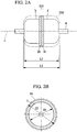
- Figs. 2A and 2B show a casing structure of a gas turbine in the axial two piece-configuration, and are respectively a plan view and a side view as viewed from the axial direction.
- Hatched portions 1A and 2A indicate connection flanges provided on the casings 1 and 2 which are divided in the axial direction, and the connection flanges project from the casings 1 and 2.
- the entire length of the casing 101 is defined as L1, and the diameter of the casing 101 is defined as D1.
- L1 is greater than D1.
- an outer shape of the pressure vessel is shown with a chain double-dashed line 200, and its length is defined as L2 and its diameter is defined as D2.
- Figs. 3A and 3B show a casing structure of a gas turbine in which the casing is divided into two on a horizontal surface, and are respectively a plan view and a side view as viewed from the axial direction.
- Hatched portions 111A and 112A indicate connection flanges provided respectively on a casing 111 located on the upper side (upper casing) and a casing 112 located on the lower side (lower casing) in the casing divided on the horizontal surface, and the connection flanges project radially outward and axially outward from the casing 111 and the casing 112 around the rotational axis L.
- the entire length of the casing 101 is defined as L1, and a diameter of the casing 101 is defined as D1.
- L1 and D1 of the case where the casing is axially divided into two are the same.
- the outer shape of the pressure vessel is shown with chain double-dashed line 210, and its length is defined as L3 and its diameter is defined as D3.
- the region of the hatched portion of the axial two piece-configuration (configuration of the present embodiment) shown in Figs. 2A and 2B is smaller than that of the horizontal two piece-configuration (conventional configuration) shown in Figs. 3A and 3B . That is, the range of the projections of the flanges is small.
- the length L2 of the axial two piece-configuration can be reduced relative to the length L3 of the horizontal two piece-configuration by the width of projections of the flanges.
- the casing 101 can be reduced in size, the material cost and producing cost can be reduced, and the mass of the entire gas turbine 100 can be reduced. Therefore, it becomes easy to move the gas turbine 100 for inspection or other purposes, and maintainability is enhanced.
- the gas turbine can be also reduced in size, the material cost and producing cost can be reduced, and a gas turbine room can be reduced in size.
- the length L1 is longer than the diameter D1 as described above, the axial two piece-configuration results in reduction in size of the casing 101.
- the casings 1 and 2 and the blade ring 3 are assembled by sandwiching the flange 3A of the blade ring between the coupling flanges 1A and 2A of the casings 1 and 2. Then, overhang of the blade ring 3 can be reduced. More specifically, when the blade ring 3 is held at the substantially central portion in the axial direction with respect to the casing, the overhang of the blade ring 3 can be reduced as compared with the pot-like structure. In this configuration, precision of center hold of the blade ring 3 is enhanced with respect to the rotor shaft 4. Further, since the blade ring 3 is supported at substantially the central portion in the axial direction, axial thermal extension of the blade ring 3 can be equally distributed, and reliability of the gas turbine 100 is enhanced.
- connection member 3B of the blade ring 3 functions as an end plate in the pressure vessel.
- a region 12 surrounded by the casing 1 and the blade ring 3 is located on the inlet of the working fluid, and a region 13 surrounded by the casing 2 and the blade ring 3 is located on the outlet of the working fluid. Therefore, a pressure in the region 12 is higher than a pressure in the region 13.
- resistance to pressure of the connection member 3B is enhanced.
- connection member 3B is a substantially conical member in the present embodiment, the connection member 3B may have a curved surface as long as it functions as an end plate. In a case where strength required to the connection member 3B is relatively small due to a pressure difference between the regions 12 and 13, the connection member 3B may be of a flat-plate, and the shape thereof is not especially limited.
- an internal pressure load applied by the pressure of the working fluid to the coupling flanges of the divided surface can be equalized and reduced as compared with the casing is divided into two on the horizontal surface.
- a pressure receiving area A2 of the flange joining portion is substantially calculated by the following equation (2).
- a 2 L 1 ⁇ D 1
- A1 is smaller than A2 from the following equation (3).
- the internal pressure load applied to the flanges is determined by the pressure receiving area.
- the inner pressure load is lower in the axial two piece-configuration.
- Fig. 4 is a schematic diagram for describing an entire configuration of a gas turbine according to a second example of the present invention.
- a basic configuration of the gas turbine of the present example is the same as that of the first example, but a holding structure of the third coupling flange is different from that of the first example.
- only the holding structure of the third coupling flange will be described with reference to Fig. 4 , and description of other constituent elements will not be repeated.
- the constituent elements same as those of the first example are designated with the same symbols, and description thereof will not be repeated.
- the flange 3A is sandwiched between the flanges 1A and 2A of the casings 1 and 2. Therefore, there are provided two flange joining surfaces on the outer periphery of the casing 101.
- the configuration of the second example since an outer peripheral portion 3C of the flange 3A is incorporated between the flanges 1A and 2A, the flanges 1A and 2A are directly joined to each other on the outer periphery of the casing 101.
- the number of joining locations is one, and the peripheral length of the joining surface can be reduced to substantially half. Accordingly, leakage of the working fluid to outside the casing and inflow of another fluid into the casing are reduced.
- the peripheral length of the cross section of the flange joining portion is shorter in the axial two piece-configuration with respect to that of the horizontal two piece-configuration.
- Figs. 2A, 2B , 3A, and 3B schematically show the above configuration.
- Figs. 2A and 2B show the casing structure of the gas turbine of the axial two piece-configuration, and are respectively a plan view and a side view as viewed from the axial direction.
- the hatched portions 1A and 2A indicate the connection flanges provided on the casings 1 and 2 which are divided into two in the axial direction.
- the length L1 of the casing 101 is longer than the diameter D1.
- Figs. 3A and 3B show the casing structure of the gas turbine divided into two on the horizontal surface, and are respectively a plan view and a side view as viewed from the axial direction.
- the hatched portions 111A and 111B indicate the connection flanges provided respectively on the casing 111 and the casing 112 divided on the horizontal surface.
- a peripheral length L11 of the cross section of the flange joining portion is substantially calculated by the following equation (5).
- L 11 2 ⁇ L 1 + D 1
- L10 is smaller than L11 from the following equation (6).
- the peripheral length of the cross section of the flange joining portion is shorter in the axial two piece-configuration with respect to that in the horizontal two piece-configuration.
- the present invention is applied to the axial-flow turbine in the above embodiments, the present invention is not limited to the axial-flow turbine, but the present invention can also be applied to other kinds of turbines such as a centrifugal type turbine and a diagonal-flow turbine.
- the present invention can also be applied to a general rotary machine of a gas turbine of another type in which air is used as a working fluid and combustion energy of fossil fuel is used as a heat source, a steam turbine, a compressor, or a pump, with no special limitations.
Landscapes
- Engineering & Computer Science (AREA)
- Mechanical Engineering (AREA)
- General Engineering & Computer Science (AREA)
- Turbine Rotor Nozzle Sealing (AREA)
- Structures Of Non-Positive Displacement Pumps (AREA)
- Wind Motors (AREA)
Description
- The present invention relates to a rotary machine used for a steam turbine, a gas turbine, or the like.
- Generally, a casing used for a steam turbine or a gas turbine is divided into two, i.e., an upper casing and a lower casing in which a rotor shaft is incorporated, and these casings are coupled to each other on a horizontal surface using a bolt (see Patent Japanese Unexamined Utility Model Application, Publication No.
S60-195908 - Alternatively, in a turbine so-called "pot-like turbine", the casing is integrally formed as one piece, a rotor shaft portion is inserted from one end opening of the casing, and the end opening is hermetically closed by fastening a screw ring which is engaged with a screw portion provided on an inner periphery of the casing (see Patent Japanese Unexamined Patent Application, Publication No.
S59-213907 - It is an object of the casing structure described above is to secure rigidity of the entire apparatus with respect to working fluid having high temperature and high pressure, and to prevent leak of the working fluid.
- In the casing structure in which the casing is divided into two on the horizontal surface as described above, the upper casing and the lower casing are provided on entire peripheries of the horizontal surfaces thereof with joining flanges, which project from the entire periphery of the horizontal surface of the casing and thus there is a problem that the joined casing itself is increased in size.
- Further, when the casing is increased in size, there is a problem that the mass of the entire turbine is increased, and costs for the material cost and production are increased.
- If the working fluid leaks from the joining surface between the upper casing and the lower casing, there is a concern that performance of the turbine is affected. However, when the casing is divided into two on the horizontal surface, the joining surface extends over the entire periphery of the horizontal surface of the casing, and thus there is a problem that a range is increased from which the working fluid leaks. In the above-described structure, since a penetrating portion of the rotor shaft is located on the joining surface of the casing, there is a problem that the working fluid leaks easier.
- In the pot-like casing structure, it can be considered that the range from which the working fluid leaks can be reduced as compared with a case where the casing is provided on the entire periphery with the joining flanges. However, the above structure in which the casing is hermetically closed can be employed only to a relatively small turbine, and such a structure must be replaced with a structure provided with flanges in a large turbine. In this case, there are problems that the flange and the joining bolt project in the axial direction, the entire length of the casing is increased, and the entire rotary machine is increased in size.
- For example, in a turbine using a working fluid including a certain material that must be carefully handled, it is not allowed to leak the working fluid to atmosphere. Thus, a pressure vessel (outer casing) which further covers the casing is provided, a clean fluid which is not contaminated by the certain material is charged under higher pressure than the working fluid in a space between the pressure vessel and the casing, thereby preventing the fluid in the casing from leaking outside (see
Fig. 5 ). -
Fig. 5 shows a configuration in which acasing 101 of the turbine body described above is accommodated in a pressure vessel (outer casing) 200. Constituent parts of the turbine are accommodated in the casing 101 (not shown). Arotor shaft 4 penetrates thecasing 101 and thepressure vessel 200. A clean fluid which has pressure higher than the working fluid in the turbine and which is not contaminated by a certain material is charged in aspace 201 between thecasing 101 and thepressure vessel 200 so as to prevent the fluid in thecasing 101 from leaking outside. However, in the above-described configuration, because of increase in size of thecasing 101, thepressure vessel 200 is also increased in size. - When the interior of the above turbine is contaminated with a certain material, the turbine cannot be opened and inspected on a site in its installed state for safety reasons unlike a general gas turbine or a steam turbine. Therefore, it is necessary to open and inspect the turbine after moving each turbine casing from the turbine room to a special maintenance area. In such a case, there are problems that, because of increase in size of the casing, it is difficult to secure rigidity of the room, and a crane capacity for hoisting the casing is largely affected.
- In the pot-like casing structure described above, a blade ring which holds turbine stator blades is mainly supported at the end opening. However, in this state, the blade ring is supported in a cantilever manner. Especially in a large turbine, when the blade ring is supported in a cantilever manner, an overhang of the blade ring is made longer and thus, there are problems that a center is not sufficiently be held, and influence of a difference in thermal extension in the axial direction between a rotating portion and a stationary portion is increased.
-
GB 2 024 958 A - Similar rotary machines, which form the background of the invention, are described in
EP 1 059 420 A1US 4,149,826 A ,US 5,593,277 A ,EP 1 519 009 A1 andEP 1 775 427 A1 . Another document isJP S58 32902 A - The present invention has been accomplished to solve the above problems, and it is an object of the present invention to provide a rotary machine according to
claim 1 which can be reduced in size and which can enhance reliability and performance - In order to achieve the above object, the present invention provides the following means.
- A casing structure of a turbine according to the present invention includes the features of
claim 1. - According to the above aspect, the casing is divided into two in the axial direction, for example on a division surface
intersecting with the rotor shaft, and the casing can be reduced in size as compared with a case where the casing is divided into two on the horizontal surface, e.g., on a division surface extending along the rotor shaft. - More specifically, when the casing is divided into two on the horizontal surface, coupling flanges used for fastening the divided casings to each other project outward from the entire periphery of the casing. In a general steam turbine or a gas turbine, a cross sectional area of a casing divided into two on vertical surface perpendicular to the rotor shaft becomes smaller than a horizontal cross section of a casing divided into two on the horizontal surface. Therefore, in the casing which is divided into two (first casing and second casing) in the axial direction, the projecting range of the coupling flanges can be made smaller as compared with the casing divided into two on the horizontal surface. In this configuration, the casing can be reduced in size.
- According to the above aspect, the third coupling flange which extends from the blade ring in a direction intersecting with the axial direction, more preferably, in a substantially vertical direction, is sandwiched between the first coupling flange of the first casing and the second coupling flange of the second casing which are divided in the axial direction, in assembling the first casing, the second casing and the blade ring. In this configuration, overhang of the blade ring can be reduced.
- More specifically, by holding the blade ring with respect to the casing via the third coupling flange located at substantially a central portion of the blade ring in the axial direction, the overhang of the blade ring can be reduced as compared with the pot-like structure described in Japanese Unexamined Patent Application, Publication No.
S59-213907 - In the above aspect, it is preferable that an inner peripheral side of a connection member disposed between the blade ring and the casing projects from the high-pressure side toward the low-pressure side of the working fluid. In other words, it is preferable that the joining member is a conical member which is disposed between the blade ring and the third coupling flange, and which inclines from the high-pressure side to the low-pressure side of the working fluid flowing between the rotor blade and the stator blade radially outward around the rotor shaft.
- In this configuration, since the connection member functions as an end plate of the pressure vessel, strength of the connection member is enhanced.
- According to the above aspect, the casing is divided into two in the axial direction. Thus, leakage of the working fluid to outside the casing and inflow of another fluid into the casing are reduced as compared with a case where the casing is divided into two on the horizontal surface. That is, there is no joining surface of the flange in the penetrating portion of the rotor shaft, leakage of the working fluid to outside the casing and inflow of another fluid into the casing are reduced.
- In the above aspect, an outer peripheral surface of the third coupling flange sandwiched between the first and second coupling flanges of the first and second casings divided in the axial direction may be enclosed between the first and second coupling flanges. In other words, the first coupling flange and the second coupling flange may be directly joined to each other radially outside around the rotor shaft, and the first coupling flange and the second coupling flange may be joined radially inside with the third coupling flange sandwiched therebetween.
- In this configuration, only one flange coupling surface is provided on the outer peripheral surface of the casing and the range of the joining surface can be reduced. Therefore, leakage of the working fluid to outside the casing and inflow of another fluid into the casing are further reduced.
- In the above aspect, it is preferable that a pressure vessel accommodating the casing therein is provided outside the casing, and a fluid with a pressure higher than the working fluid flowing between the rotor blades and the stator blades is filled in a space between the casing and the pressure vessel.
- According to the above aspect, the working fluid is prevented from flowing into the space between the casing and the pressure vessel by charging a fluid having pressure higher than that of the working fluid into the space. Therefore, the working fluid is prevented from flowing outside the casing.
- According to the rotary machine of the present invention, the casing is divided into two in the axial direction, there are effects that the casing and the pressure vessel (outer casing) enclosing the casing therein can be reduced in size, leakage of the working fluid to outside the casing and inflow of another fluid into the casing are reduced, and reliability and performance of the rotary machine are enhanced.
- Further, holding precision of the center of the blade ring with respect to the rotor shaft is enhanced, and reliability of the rotary machine is enhanced.
-
-
Fig. 1 is a schematic diagram for describing an entire configuration of a gas turbine according to a first example of the present invention. -
Fig. 2A is a schematic plan view of an axial two piece-configuration of a casing structure. -
Fig. 2B is an axial schematic side view of the axial two piece-configuration of the casing structure. -
Fig. 3A is a schematic plan view of a horizontal two piece-configuration of the casing structure. -
Fig. 3B is an axial schematic side view of the horizontal two piece-configuration of the casing structure. -
Fig. 4 is a schematic diagram for describing an entire configuration of a gas turbine according to a second example of the present invention. -
Fig. 5 is a schematic diagram for describing a configuration in which a casing of a gas turbine is accommodated in a pressure vessel. - A casing structure of a gas turbine and the gas turbine having such a casing structure according to an embodiment of the present invention will be described with reference to
Figs. 1 to 5 . -
Fig. 1 is a schematic diagram for describing an entire configuration of the gas turbine according to a first example of the present invention. - As shown in
Fig. 1 , a gas turbine (rotary machine) 100 includes acasing 101 constituting an outer shape of thegas turbine 100, ablade ring 3 which holdsturbine stator blades 10 on an inner periphery thereof, arotor shaft 4 in whichturbine rotor blades 11 are embedded, aninlet scroll portion 5 which supplies a working fluid to a first stage of theturbine stator blades 10, and a discharge scroll portion 6 into which the working fluid discharged from a last stage of theturbine rotor blades 11 flows. - In the
gas turbine 100, the working fluid is accelerated by theturbine stator blades 10, theturbine rotor blades 11 are blown with the accelerated working fluid, and thermal energy of the working fluid is converted into mechanical rotation energy. Therotor shaft 4 is rotated and power is thus taken out. There are generally provided the plurality ofturbine stator blades 10 andturbine rotor blades 11. - As shown in
Fig. 1 , thecasing 101 constitutes the outer shape of thegas turbine 100. Theblade ring 3, therotor shaft 4, theinlet scroll portion 5 and the discharge scroll portion 6 are accommodated in thecasing 101. Thecasing 101 is divided into two, namely a high-pressure casing 1 (first casing) and a low-pressure casing 2 (second casing), at substantially a central portion in a direction along therotor shaft 4. - The
casings casings casings flanges casings casings flange 3A of the later-describedblade ring 3 interposed between theflanges - A through hole 7 into which the
rotor shaft 4 is inserted is formed in closed ends of thecasings opening 8 into which a tube is inserted is provided in cylindrical surfaces of thecasings - As shown in
Fig. 1 , theblade ring 3 surrounds therotor shaft 4 together with thecasings gas turbine 100 and supports theturbine stator blades 10. - The
blade ring 3 includes a substantially cylindrical member extending in the axial direction around a rotational axis L, theflange 3A disposed on the outermost peripheral portion, and substantiallyconical connection member 3B which holds the substantially cylindrical blade ring member by theflange 3A, and theflange 3A is sandwiched between theflanges turbine stator blades 10 are held on the inner periphery of theblade ring 3. Theflange 3A is located at substantially the center of the axial length of theblade ring 3. - The
turbine rotor blades 11 are embedded in therotor shaft 4, and as shown inFig. 1 , theturbine rotor blade 11 is blown with the working fluid accelerated by theturbine stator blades 10, so that therotor shaft 4 is rotated and driven around the rotational axis L. Generally, the plurality ofturbine stator blades 10 and the plurality ofturbine rotor blades 11 are alternately provided, but a known configurations may be employed thereto with no special limitation. - As shown in
Fig. 1 , the working fluid flows through theinlet scroll portion 5 and the discharge scroll portion 6. Theinlet scroll portion 5 supplies the working fluid to the first stage of theturbine stator blades 10, and the working fluid discharged from the last stage of theturbine rotor blades 11 flows into the discharge scroll portion 6. - Operation of the
gas turbine 100 having the above-described configuration will be described next. - As shown in
Fig. 1 , in a high-temperature gas furnace, the working fluid heated to a high temperature flows into theinlet scroll portion 5 of thegas turbine 100. The working fluid which has flowed into theinlet scroll portion 5 flows into anannular channel 31, and flows into acylindrical channel 32 at substantially a constant flow rate in the circumferential direction. The working fluid which has flowed into thecylindrical channel 32 is introduced toward the first stage of theturbine stator blades 10. - As shown in
Fig. 1 , theturbine rotor blades 11 are rotated and driven by the flowing working fluid, and a rotational driving force extracted by therotor blades 11 is transmitted to therotor shaft 4. The working fluid from which rotational driving force is extracted by theturbine rotor blades 11 and of which temperature is lowered is discharged from the last stage of theturbine rotor blades 11. - The working fluid which was discharged from the last stage of the
turbine rotor blades 11 flows into thecylindrical channel 32 of the discharge scroll portion 6 as shown inFig. 1 , and flows toward theannular channel 31. The working fluid which has flowed into theannular channel 31 is discharged from the discharge scroll portion 6, i.e., from thegas turbine 100, and is again introduced into the high-temperature gas furnace through each system. - According to the above configuration, in a case where the
casing 101 is divided into two in the axial direction, thecasing 101 can be reduced in size as compared with a casing which is divided into two on a horizontal surface. More specifically, theflanges casings casing 101. However, since the area of the cross section which is vertical in the axial direction is smaller than that of a horizontal cross section, a range of
projections of the flanges can be made smaller in the casing which is axially divided into two as compared with a configuration in which the casing is divided into two on the horizontal surface. -
Figs. 2A, 2B ,3A, and 3B schematically show the above-described configuration. -
Figs. 2A and 2B show a casing structure of a gas turbine in the axial two piece-configuration, and are respectively a plan view and a side view as viewed from the axial direction. Hatchedportions casings casings casing 101 is defined as L1, and the diameter of thecasing 101 is defined as D1. In a general gas turbine, L1 is greater than D1. Here, when a cylindrical pressure vessel is provided outside thecasings line 200, and its length is defined as L2 and its diameter is defined as D2. -
Figs. 3A and 3B show a casing structure of a gas turbine in which the casing is divided into two on a horizontal surface, and are respectively a plan view and a side view as viewed from the axial direction. Hatchedportions casing 111 located on the upper side (upper casing) and a
casing 112 located on the lower side (lower casing) in the casing divided on the horizontal surface, and the connection flanges project radially outward and axially outward from thecasing 111 and thecasing 112 around the rotational axis L. The entire length of thecasing 101 is defined as L1, and a diameter of thecasing 101 is defined as D1. In the gas turbine itself in the same shape, L1 and D1 of the case where the casing is axially divided into two (configuration of the present embodiment) and those of the case where the casing is divided into two on the horizontal surface are the same. When the cylindrical pressure vessel is provided outside thecasing 111 and thecasing 112, the outer shape of the pressure vessel is shown with chain double-dashedline 210, and its length is defined as L3 and its diameter is defined as D3. - As apparent from the drawings, the region of the hatched portion of the axial two piece-configuration (configuration of the present embodiment) shown in
Figs. 2A and 2B is smaller than that of the horizontal two piece-configuration (conventional configuration) shown inFigs. 3A and 3B . That is, the range of the projections of the flanges is small. - Also in the case where the pressure vessel is provided outside the
casing 101, while the diameter D2 of the axial two piece-configuration and the diameter D3 of the horizontal two piece-configuration are equal to each other, the length L2 of the axial two piece-configuration can be reduced relative to the length L3 of the horizontal two piece-configuration by the width of projections of the flanges. - In this configuration, the
casing 101 can be reduced in size, the material cost and producing cost can be reduced, and the mass of theentire gas turbine 100 can be reduced. Therefore, it becomes easy to move thegas turbine 100 for inspection or other purposes, and maintainability is enhanced. When thepressure vessel 200 is provided outside thegas turbine 100, the gas turbine can be also reduced in size, the material cost and producing cost can be reduced, and a gas turbine room can be reduced in size. In a general gas turbine, since the length L1 is longer than the diameter D1 as described above, the axial two piece-configuration results in reduction in size of thecasing 101. - According to the above configuration, the
casings blade ring 3 are assembled by sandwiching theflange 3A of the blade ring between thecoupling flanges casings blade ring 3 can be reduced. More specifically, when theblade ring 3 is held at the substantially central portion in the axial direction with respect to the casing, the overhang of theblade ring 3 can be reduced as compared with the pot-like structure. In this configuration, precision of center hold of theblade ring 3 is enhanced with respect to therotor shaft 4. Further, since theblade ring 3 is supported at substantially the central portion in the axial direction, axial thermal extension of theblade ring 3 can be equally distributed, and reliability of thegas turbine 100 is enhanced. - According to the above configuration, the
connection member 3B of theblade ring 3 functions as an end plate in the pressure vessel. Aregion 12 surrounded by thecasing 1 and theblade ring 3 is located on the inlet of the working fluid, and aregion 13 surrounded by thecasing 2 and theblade ring 3 is located on the outlet of the working fluid. Therefore, a pressure in theregion 12 is higher than a pressure in theregion 13. Thus, when the inner periphery of theconnection member 3 in the radial direction projects from the high-pressure region 12 to the low-pressure region 13, resistance to pressure of theconnection member 3B is enhanced. - Although the
connection member 3B is a substantially conical member in the present embodiment, theconnection member 3B may have a curved surface as long as it functions as an end plate. In a case where strength required to theconnection member 3B is relatively small due to a pressure difference between theregions connection member 3B may be of a flat-plate, and the shape thereof is not especially limited. - According to the above configuration, when the
casing 101 is divided into two in the axial direction, leakage of the working fluid to outside and inflow caused by entrainment of another fluid into the casing from outside can be reduced as compared with the horizontal two piece-configuration. More specifically, since there is no flange joining surface provided in the penetrating portion of the rotor shaft, leakage of the working fluid to outside the casing and inflow of another fluid into the casing are further reduced. - According to the above configuration, by dividing the
casing 101 into two in the axial direction, an internal pressure load applied by the pressure of the working fluid to the coupling flanges of the divided surface can be equalized and reduced as compared with the casing is divided into two on the horizontal surface. - When the casing is divided into two on the horizontal surface, since a high pressure portion and a low pressure portion exist in the casing as described above, the internal pressure load applied to the coupling flanges is varied depending upon locations. Therefore, it is necessary to take such variation into consideration upon designing strength of a bolt for fastening flanges or strength of the flanges itself. When the
casing 101 is divided into two in the axial direction, since a load applied to theflanges Figs. 2A, 2B ,3A, and 3B , the internal pressure load applied to the flanges can also be reduced. - In the axial two piece-configuration, a pressure receiving area A1 of the flange joining portion is substantially calculated by the following equation (1),

- In the the horizontal two piece-configuration, a pressure receiving area A2 of the flange joining portion is substantially calculated by the following equation (2).

- In this case, because of π ≈ 3.14 and L1 > D1, it can be found that A1 is smaller than A2 from the following equation (3).

- When the pressure applied to a division surface in the axial two piece-configuration and the horizontal two piece-configuration is obtained by averaging the pressure of the high pressure portion and the pressure of the low pressure portion, which are equal to each other, the internal pressure load applied to the flanges is determined by the pressure receiving area. Thus, the inner pressure load is lower in the axial two piece-configuration.
-
Fig. 4 is a schematic diagram for describing an entire configuration of a gas turbine according to a second example of the present invention. A basic configuration of the gas turbine of the present example is the same as that of the first example, but a holding structure of the third coupling flange is different from that of the first example. In the present example, only the holding structure of the third coupling flange will be described with reference toFig. 4 , and description of other constituent elements will not be repeated. The constituent elements same as those of the first example are designated with the same symbols, and description thereof will not be repeated. - In the second example, as shown in
Fig. 4 , an outer peripheral surface of theflange 3A sandwiched between theflanges 1A and 1B of thecasings casing 101 of agas turbine 300 is incorporated between theflanges - In the first example, the
flange 3A is sandwiched between theflanges casings casing 101. On the other hand, according to the configuration of the second example, since an outerperipheral portion 3C of theflange 3A is incorporated between theflanges flanges casing 101. In this configuration, the number of joining locations is one, and the peripheral length of the joining surface can be reduced to substantially half. Accordingly, leakage of the working fluid to outside the casing and inflow of another fluid into the casing are reduced. - According to the above-described configuration, the peripheral length of the cross section of the flange joining portion is shorter in the axial two piece-configuration with respect to that of the horizontal two piece-configuration. When the
casing 101 is divided into two in the axial direction, the range of the joining surface can be reduced as compared with the case where the casing is divided into two on the horizontal surface. Accordingly, leakage of the working fluid to outside the casing and inflow of another fluid into the casing are reduced. -
Figs. 2A, 2B ,3A, and 3B schematically show the above configuration. - As described also in the first example,
Figs. 2A and 2B show the casing structure of the gas turbine of the axial two piece-configuration, and are respectively a plan view and a side view as viewed from the axial direction. The hatchedportions casings casing 101 is longer than the diameter D1. The peripheral length L10 of the cross section of the flange joining portion is substantially calculated by the following equation (4),
-
Figs. 3A and 3B show the casing structure of the gas turbine divided into two on the horizontal surface, and are respectively a plan view and a side view as viewed from the axial direction. The hatchedportions 111A and 111B indicate the connection flanges provided respectively on thecasing 111 and thecasing 112 divided on the horizontal surface. Similarly, when the entire length of thecasing 101 is defined as L1 and the diameter of the casing is defined as D1, a peripheral length L11 of the cross section of the flange joining portion is substantially calculated by the following equation (5).
- Because of π ≈ 3.14 and L1 > D1, it can be found that L10 is smaller than L11 from the following equation (6).

- Accordingly, the peripheral length of the cross section of the flange joining portion is shorter in the axial two piece-configuration with respect to that in the horizontal two piece-configuration. When the
casing 101 is divided into two in the axial direction, the range of the joining surface can be reduced as compared with the case where the casing is divided into two on the horizontal surface. Accordingly, leakage of the working fluid to outside the casing and inflow of another fluid into the casing can further be reduced, and thus, reliability of thegas turbine 300 can be enhanced. - The scope of the present invention is not limited to the above embodiments, and the present invention can variously be modified within a range not departing from the subject matter of the invention.
- For example, although the present invention is applied to the axial-flow turbine in the above embodiments, the present invention is not limited to the axial-flow turbine, but the present invention can also be applied to other kinds of turbines such as a centrifugal type turbine and a diagonal-flow turbine.
- The present invention can also be applied to a general rotary machine of a gas turbine of another type in which air is used as a working fluid and combustion energy of fossil fuel is used as a heat source, a steam turbine, a compressor, or a pump, with no special limitations.
Claims (3)
- A rotary machine, comprisinga first casing (1) and a second casing (2) formed by dividing a substantially cylindrical casing (101), enclosing in the interior thereof a rotor shaft (4) in which rotor blades (11) are embedded, into two at substantially a central portion relative to an axial direction of the rotor shaft (4);a first coupling flange (1A) and a second coupling flange (2A) at openings in the first casing (1) and the second casing (2), respectively;a through hole (7) into which the rotor shaft (4) is inserted is formed in each closed end of the first casing (1) and the second casing (2), respectively;a third coupling flange (3A), which is enclosed by the casing,the third coupling flange (3A) holding a substantially cylindrical blade ring member (3) and being positioned at substantially a central position of the length in the axial direction, the blade ring member (3) holding stator blades (10) and enclosing the rotor shaft (4), characterised in that the first casing (1), the second casing (2), and the blade ring (3) being assembled by sandwiching the third coupling flange (3A) between the first coupling flange (1A) and the second coupling flange (2A), such that the first casing is a high-pressure casing and the second casing is a low-pressure casing;
wherein the rotor shaft (4) is inserted into the through holes (7) formed in the closed ends of the first casing (1) and the second casing (2),a pressure vessel (210) accommodating the casing (101) therein is provided outside the casing; and is configured to containa fluid with a pressure higher than the working fluid flowing between the rotor blades (4) and the stator blades (10). - A rotary machine according to Claim 1, whereinthe blade ring (3) is held relative to the third coupling flange (3A) by a substantially conical connection member (3B), andan inner peripheral surface at the blade ring side of the connection member (3B) projects from a high-pressure side to a low-pressure side in a working fluid flowing between the rotor blades (11) and the stator blades (10).
- A rotary machine according to Claim 1 or 2, wherein an outer peripheral portion of the third coupling flange (3A) is contained between the first coupling flange (1A) and the second coupling flange (2A).
Applications Claiming Priority (2)
| Application Number | Priority Date | Filing Date | Title |
|---|---|---|---|
| JP2008093753 | 2008-03-31 | ||
| PCT/JP2009/056929 WO2009123301A2 (en) | 2008-03-31 | 2009-03-27 | Rotary machine |
Publications (2)
| Publication Number | Publication Date |
|---|---|
| EP2276912A2 EP2276912A2 (en) | 2011-01-26 |
| EP2276912B1 true EP2276912B1 (en) | 2017-10-25 |
Family
ID=41136028
Family Applications (1)
| Application Number | Title | Priority Date | Filing Date |
|---|---|---|---|
| EP09728480.6A Active EP2276912B1 (en) | 2008-03-31 | 2009-03-27 | Rotary machine |
Country Status (7)
| Country | Link |
|---|---|
| US (1) | US20100260599A1 (en) |
| EP (1) | EP2276912B1 (en) |
| JP (1) | JP4969688B2 (en) |
| CN (1) | CN101952557A (en) |
| RU (1) | RU2483218C2 (en) |
| WO (1) | WO2009123301A2 (en) |
| ZA (1) | ZA201003458B (en) |
Families Citing this family (5)
| Publication number | Priority date | Publication date | Assignee | Title |
|---|---|---|---|---|
| JP6483106B2 (en) | 2013-06-28 | 2019-03-13 | エクソンモービル アップストリーム リサーチ カンパニー | System and method utilizing an axial flow expander |
| EP3014077B1 (en) | 2013-06-28 | 2018-01-17 | Mitsubishi Heavy Industries Compressor Corporation | Axial flow expander |
| EP3128134A1 (en) * | 2015-08-06 | 2017-02-08 | Siemens Aktiengesellschaft | Assembly for a steam turbine and corresponding fixation method |
| JP7539598B2 (en) * | 2022-02-25 | 2024-08-23 | 三菱重工業株式会社 | Method for estimating flange displacement of rotating machine, program for executing this method, and device for executing this method |
| CN115163225A (en) * | 2022-07-03 | 2022-10-11 | 中国船舶重工集团公司第七0三研究所 | Cylindrical cylinder structure without median plane |
Citations (2)
| Publication number | Priority date | Publication date | Assignee | Title |
|---|---|---|---|---|
| JPS5832902A (en) * | 1981-08-20 | 1983-02-26 | Toshiba Corp | Steam turbine |
| WO2007094306A1 (en) * | 2006-02-14 | 2007-08-23 | Mitsubishi Heavy Industries, Ltd. | Casing and fluid machine |
Family Cites Families (18)
| Publication number | Priority date | Publication date | Assignee | Title |
|---|---|---|---|---|
| US2374122A (en) * | 1942-12-05 | 1945-04-17 | Arthur J Nelson | Double case pump |
| US2408637A (en) * | 1944-07-31 | 1946-10-01 | Smith Corp A O | Double-casing high-pressure pump |
| US2815645A (en) * | 1955-03-01 | 1957-12-10 | Gen Electric | Super-critical pressure elastic fluid turbine |
| SE403393B (en) * | 1976-07-05 | 1978-08-14 | Stal Laval Turbin Ab | GAS TURBINE |
| US4222708A (en) * | 1978-06-26 | 1980-09-16 | General Electric Company | Method and apparatus for reducing eccentricity in a turbomachine |
| SU832089A1 (en) * | 1979-04-16 | 1981-05-23 | Ордена Ленина И Ордена Трудовогокрасного Знамени Производственноеобъединение "Невский Завод" Им. B.И.Ленина | Turbine machine body |
| JPS593103A (en) * | 1982-06-29 | 1984-01-09 | Hitachi Zosen Corp | Variable stator vane device in turbine |
| JPS6216701U (en) * | 1985-07-15 | 1987-01-31 | ||
| SU1399485A1 (en) * | 1986-06-10 | 1988-05-30 | А. И. Григорьев, К. И. Сбитнев, В. В. Вдовиков и Н. Е. Першин | Method of fastening flanges of steam turbine vertical joint |
| FR2608715B1 (en) * | 1986-12-19 | 1989-12-01 | Srti Soc Rech Tech Ind | LIQUID LEAKAGE PREVENTION METHOD, AND DEVICE PROVIDED WITH MEANS FOR CARRYING OUT SAID METHOD |
| US5080557A (en) * | 1991-01-14 | 1992-01-14 | General Motors Corporation | Turbine blade shroud assembly |
| US5593277A (en) * | 1995-06-06 | 1997-01-14 | General Electric Company | Smart turbine shroud |
| CZ326498A3 (en) * | 1996-04-11 | 1999-02-17 | Siemens Aktiengesellschaft | Method of equalizing feed in a turbo-machine and the turbo-machine per se |
| FR2794816B1 (en) * | 1999-06-10 | 2001-07-06 | Snecma | HIGH PRESSURE COMPRESSOR STATOR |
| DE60121968T2 (en) * | 2001-11-22 | 2006-12-07 | Siemens Ag | Process for the manufacture of steam turbines |
| FR2860041B1 (en) * | 2003-09-22 | 2005-11-25 | Snecma Moteurs | REALIZING THE SEALING IN A TURBOJET FOR THE DOUBLE BALL TUBE COLLECTION |
| FR2891300A1 (en) * | 2005-09-23 | 2007-03-30 | Snecma Sa | DEVICE FOR CONTROLLING PLAY IN A GAS TURBINE |
| US7273348B2 (en) * | 2005-09-23 | 2007-09-25 | General Electric Company | Method and assembly for aligning a turbine |
-
2009
- 2009-03-27 WO PCT/JP2009/056929 patent/WO2009123301A2/en not_active Ceased
- 2009-03-27 JP JP2010524005A patent/JP4969688B2/en not_active Expired - Fee Related
- 2009-03-27 EP EP09728480.6A patent/EP2276912B1/en active Active
- 2009-03-27 US US12/746,355 patent/US20100260599A1/en not_active Abandoned
- 2009-03-27 CN CN2009801013114A patent/CN101952557A/en active Pending
- 2009-03-27 RU RU2010125558/06A patent/RU2483218C2/en active
-
2010
- 2010-05-17 ZA ZA2010/03458A patent/ZA201003458B/en unknown
Patent Citations (2)
| Publication number | Priority date | Publication date | Assignee | Title |
|---|---|---|---|---|
| JPS5832902A (en) * | 1981-08-20 | 1983-02-26 | Toshiba Corp | Steam turbine |
| WO2007094306A1 (en) * | 2006-02-14 | 2007-08-23 | Mitsubishi Heavy Industries, Ltd. | Casing and fluid machine |
Also Published As
| Publication number | Publication date |
|---|---|
| CN101952557A (en) | 2011-01-19 |
| JP4969688B2 (en) | 2012-07-04 |
| WO2009123301A2 (en) | 2009-10-08 |
| US20100260599A1 (en) | 2010-10-14 |
| RU2483218C2 (en) | 2013-05-27 |
| JP2011506809A (en) | 2011-03-03 |
| RU2010125558A (en) | 2012-05-10 |
| EP2276912A2 (en) | 2011-01-26 |
| WO2009123301A3 (en) | 2010-09-16 |
| ZA201003458B (en) | 2013-02-27 |
Similar Documents
| Publication | Publication Date | Title |
|---|---|---|
| JP6141871B2 (en) | High temperature gas expansion device inlet casing assembly and method | |
| US8221062B2 (en) | Device and system for reducing secondary air flow in a gas turbine | |
| JP5364609B2 (en) | Turbine cover plate system | |
| US8727719B2 (en) | Annular flange for fastening a rotor or stator element in a turbomachine | |
| EP2187019A1 (en) | Exhaust section structure of gas turbine and gas turbine | |
| US8651809B2 (en) | Apparatus and method for aligning a turbine casing | |
| US8757964B2 (en) | Rotary machine scroll structure and rotary machine | |
| US9828874B2 (en) | Annular cover delimiting a turbomachine lubrication chamber | |
| CN102203389A (en) | Gas turbine having sealing plates on the turbine disc | |
| EP2596215B1 (en) | A seal assembly for controlling fluid flow | |
| EP3141698A1 (en) | Arrangement for a gas turbine | |
| US20100260599A1 (en) | Rotary machine | |
| EP2283218B1 (en) | Thermal insulation structure | |
| EP3051072B1 (en) | Airfoil module | |
| JPH0270903A (en) | Turbine | |
| EP3246517B1 (en) | Fastener openings for stress distribution | |
| US20100158675A1 (en) | Turbomachine rotor having blades of composite material provided with metal labyrinth teeth | |
| CN203847245U (en) | Balance weight and system for mounting and removing lower portions of inner shells of turbine segments of gas turbines | |
| EP3222811A1 (en) | Damping vibrations in a gas turbine | |
| JP6888941B2 (en) | Systems and methods for turbine diffusers | |
| CN102996188A (en) | Turbine casing assembly mounting pin | |
| RU2291306C2 (en) | Turbomachine in form of turbine of compressor and method to its assembling | |
| US7866949B2 (en) | Methods and apparatus for fabricating a rotor for a steam turbine | |
| JP6956482B2 (en) | System supporting the turbine diffuser | |
| JP2026508146A (en) | Power turbine shaft with hub assembly for a gas turbine engine - Patent Application 20070122997 |
Legal Events
| Date | Code | Title | Description |
|---|---|---|---|
| PUAI | Public reference made under article 153(3) epc to a published international application that has entered the european phase |
Free format text: ORIGINAL CODE: 0009012 |
|
| 17P | Request for examination filed |
Effective date: 20100527 |
|
| AK | Designated contracting states |
Kind code of ref document: A2 Designated state(s): AT BE BG CH CY CZ DE DK EE ES FI FR GB GR HR HU IE IS IT LI LT LU LV MC MK MT NL NO PL PT RO SE SI SK TR |
|
| DAX | Request for extension of the european patent (deleted) | ||
| 17Q | First examination report despatched |
Effective date: 20160118 |
|
| GRAP | Despatch of communication of intention to grant a patent |
Free format text: ORIGINAL CODE: EPIDOSNIGR1 |
|
| INTG | Intention to grant announced |
Effective date: 20170620 |
|
| GRAS | Grant fee paid |
Free format text: ORIGINAL CODE: EPIDOSNIGR3 |
|
| GRAA | (expected) grant |
Free format text: ORIGINAL CODE: 0009210 |
|
| AK | Designated contracting states |
Kind code of ref document: B1 Designated state(s): AT BE BG CH CY CZ DE DK EE ES FI FR GB GR HR HU IE IS IT LI LT LU LV MC MK MT NL NO PL PT RO SE SI SK TR |
|
| REG | Reference to a national code |
Ref country code: GB Ref legal event code: FG4D |
|
| REG | Reference to a national code |
Ref country code: CH Ref legal event code: EP |
|
| REG | Reference to a national code |
Ref country code: AT Ref legal event code: REF Ref document number: 940165 Country of ref document: AT Kind code of ref document: T Effective date: 20171115 |
|
| REG | Reference to a national code |
Ref country code: IE Ref legal event code: FG4D |
|
| REG | Reference to a national code |
Ref country code: DE Ref legal event code: R096 Ref document number: 602009049014 Country of ref document: DE |
|
| REG | Reference to a national code |
Ref country code: FR Ref legal event code: PLFP Year of fee payment: 10 |
|
| REG | Reference to a national code |
Ref country code: NL Ref legal event code: MP Effective date: 20171025 |
|
| REG | Reference to a national code |
Ref country code: LT Ref legal event code: MG4D |
|
| REG | Reference to a national code |
Ref country code: AT Ref legal event code: MK05 Ref document number: 940165 Country of ref document: AT Kind code of ref document: T Effective date: 20171025 |
|
| PG25 | Lapsed in a contracting state [announced via postgrant information from national office to epo] |
Ref country code: NL Free format text: LAPSE BECAUSE OF FAILURE TO SUBMIT A TRANSLATION OF THE DESCRIPTION OR TO PAY THE FEE WITHIN THE PRESCRIBED TIME-LIMIT Effective date: 20171025 |
|
| PG25 | Lapsed in a contracting state [announced via postgrant information from national office to epo] |
Ref country code: NO Free format text: LAPSE BECAUSE OF FAILURE TO SUBMIT A TRANSLATION OF THE DESCRIPTION OR TO PAY THE FEE WITHIN THE PRESCRIBED TIME-LIMIT Effective date: 20180125 Ref country code: SE Free format text: LAPSE BECAUSE OF FAILURE TO SUBMIT A TRANSLATION OF THE DESCRIPTION OR TO PAY THE FEE WITHIN THE PRESCRIBED TIME-LIMIT Effective date: 20171025 Ref country code: ES Free format text: LAPSE BECAUSE OF FAILURE TO SUBMIT A TRANSLATION OF THE DESCRIPTION OR TO PAY THE FEE WITHIN THE PRESCRIBED TIME-LIMIT Effective date: 20171025 Ref country code: LT Free format text: LAPSE BECAUSE OF FAILURE TO SUBMIT A TRANSLATION OF THE DESCRIPTION OR TO PAY THE FEE WITHIN THE PRESCRIBED TIME-LIMIT Effective date: 20171025 |
|
| PG25 | Lapsed in a contracting state [announced via postgrant information from national office to epo] |
Ref country code: LV Free format text: LAPSE BECAUSE OF FAILURE TO SUBMIT A TRANSLATION OF THE DESCRIPTION OR TO PAY THE FEE WITHIN THE PRESCRIBED TIME-LIMIT Effective date: 20171025 Ref country code: GR Free format text: LAPSE BECAUSE OF FAILURE TO SUBMIT A TRANSLATION OF THE DESCRIPTION OR TO PAY THE FEE WITHIN THE PRESCRIBED TIME-LIMIT Effective date: 20180126 Ref country code: IS Free format text: LAPSE BECAUSE OF FAILURE TO SUBMIT A TRANSLATION OF THE DESCRIPTION OR TO PAY THE FEE WITHIN THE PRESCRIBED TIME-LIMIT Effective date: 20180225 Ref country code: HR Free format text: LAPSE BECAUSE OF FAILURE TO SUBMIT A TRANSLATION OF THE DESCRIPTION OR TO PAY THE FEE WITHIN THE PRESCRIBED TIME-LIMIT Effective date: 20171025 Ref country code: BG Free format text: LAPSE BECAUSE OF FAILURE TO SUBMIT A TRANSLATION OF THE DESCRIPTION OR TO PAY THE FEE WITHIN THE PRESCRIBED TIME-LIMIT Effective date: 20180125 Ref country code: AT Free format text: LAPSE BECAUSE OF FAILURE TO SUBMIT A TRANSLATION OF THE DESCRIPTION OR TO PAY THE FEE WITHIN THE PRESCRIBED TIME-LIMIT Effective date: 20171025 |
|
| REG | Reference to a national code |
Ref country code: DE Ref legal event code: R097 Ref document number: 602009049014 Country of ref document: DE |
|
| PG25 | Lapsed in a contracting state [announced via postgrant information from national office to epo] |
Ref country code: SK Free format text: LAPSE BECAUSE OF FAILURE TO SUBMIT A TRANSLATION OF THE DESCRIPTION OR TO PAY THE FEE WITHIN THE PRESCRIBED TIME-LIMIT Effective date: 20171025 Ref country code: CZ Free format text: LAPSE BECAUSE OF FAILURE TO SUBMIT A TRANSLATION OF THE DESCRIPTION OR TO PAY THE FEE WITHIN THE PRESCRIBED TIME-LIMIT Effective date: 20171025 Ref country code: DK Free format text: LAPSE BECAUSE OF FAILURE TO SUBMIT A TRANSLATION OF THE DESCRIPTION OR TO PAY THE FEE WITHIN THE PRESCRIBED TIME-LIMIT Effective date: 20171025 Ref country code: CY Free format text: LAPSE BECAUSE OF FAILURE TO SUBMIT A TRANSLATION OF THE DESCRIPTION OR TO PAY THE FEE WITHIN THE PRESCRIBED TIME-LIMIT Effective date: 20171025 Ref country code: EE Free format text: LAPSE BECAUSE OF FAILURE TO SUBMIT A TRANSLATION OF THE DESCRIPTION OR TO PAY THE FEE WITHIN THE PRESCRIBED TIME-LIMIT Effective date: 20171025 |
|
| PG25 | Lapsed in a contracting state [announced via postgrant information from national office to epo] |
Ref country code: PL Free format text: LAPSE BECAUSE OF FAILURE TO SUBMIT A TRANSLATION OF THE DESCRIPTION OR TO PAY THE FEE WITHIN THE PRESCRIBED TIME-LIMIT Effective date: 20171025 Ref country code: RO Free format text: LAPSE BECAUSE OF FAILURE TO SUBMIT A TRANSLATION OF THE DESCRIPTION OR TO PAY THE FEE WITHIN THE PRESCRIBED TIME-LIMIT Effective date: 20171025 Ref country code: IT Free format text: LAPSE BECAUSE OF FAILURE TO SUBMIT A TRANSLATION OF THE DESCRIPTION OR TO PAY THE FEE WITHIN THE PRESCRIBED TIME-LIMIT Effective date: 20171025 |
|
| PLBE | No opposition filed within time limit |
Free format text: ORIGINAL CODE: 0009261 |
|
| STAA | Information on the status of an ep patent application or granted ep patent |
Free format text: STATUS: NO OPPOSITION FILED WITHIN TIME LIMIT |
|
| 26N | No opposition filed |
Effective date: 20180726 |
|
| REG | Reference to a national code |
Ref country code: CH Ref legal event code: PL |
|
| PG25 | Lapsed in a contracting state [announced via postgrant information from national office to epo] |
Ref country code: SI Free format text: LAPSE BECAUSE OF FAILURE TO SUBMIT A TRANSLATION OF THE DESCRIPTION OR TO PAY THE FEE WITHIN THE PRESCRIBED TIME-LIMIT Effective date: 20171025 Ref country code: MC Free format text: LAPSE BECAUSE OF FAILURE TO SUBMIT A TRANSLATION OF THE DESCRIPTION OR TO PAY THE FEE WITHIN THE PRESCRIBED TIME-LIMIT Effective date: 20171025 |
|
| REG | Reference to a national code |
Ref country code: IE Ref legal event code: MM4A |
|
| PG25 | Lapsed in a contracting state [announced via postgrant information from national office to epo] |
Ref country code: LU Free format text: LAPSE BECAUSE OF NON-PAYMENT OF DUE FEES Effective date: 20180327 |
|
| PG25 | Lapsed in a contracting state [announced via postgrant information from national office to epo] |
Ref country code: IE Free format text: LAPSE BECAUSE OF NON-PAYMENT OF DUE FEES Effective date: 20180327 |
|
| PG25 | Lapsed in a contracting state [announced via postgrant information from national office to epo] |
Ref country code: CH Free format text: LAPSE BECAUSE OF NON-PAYMENT OF DUE FEES Effective date: 20180331 Ref country code: LI Free format text: LAPSE BECAUSE OF NON-PAYMENT OF DUE FEES Effective date: 20180331 |
|
| PG25 | Lapsed in a contracting state [announced via postgrant information from national office to epo] |
Ref country code: MT Free format text: LAPSE BECAUSE OF NON-PAYMENT OF DUE FEES Effective date: 20180327 |
|
| PG25 | Lapsed in a contracting state [announced via postgrant information from national office to epo] |
Ref country code: TR Free format text: LAPSE BECAUSE OF FAILURE TO SUBMIT A TRANSLATION OF THE DESCRIPTION OR TO PAY THE FEE WITHIN THE PRESCRIBED TIME-LIMIT Effective date: 20171025 |
|
| PG25 | Lapsed in a contracting state [announced via postgrant information from national office to epo] |
Ref country code: PT Free format text: LAPSE BECAUSE OF FAILURE TO SUBMIT A TRANSLATION OF THE DESCRIPTION OR TO PAY THE FEE WITHIN THE PRESCRIBED TIME-LIMIT Effective date: 20171025 Ref country code: HU Free format text: LAPSE BECAUSE OF FAILURE TO SUBMIT A TRANSLATION OF THE DESCRIPTION OR TO PAY THE FEE WITHIN THE PRESCRIBED TIME-LIMIT; INVALID AB INITIO Effective date: 20090327 |
|
| PG25 | Lapsed in a contracting state [announced via postgrant information from national office to epo] |
Ref country code: MK Free format text: LAPSE BECAUSE OF NON-PAYMENT OF DUE FEES Effective date: 20171025 |
|
| PGFP | Annual fee paid to national office [announced via postgrant information from national office to epo] |
Ref country code: GB Payment date: 20260223 Year of fee payment: 18 |
|
| PGFP | Annual fee paid to national office [announced via postgrant information from national office to epo] |
Ref country code: DE Payment date: 20260218 Year of fee payment: 18 |
|
| PGFP | Annual fee paid to national office [announced via postgrant information from national office to epo] |
Ref country code: FI Payment date: 20260312 Year of fee payment: 18 Ref country code: BE Payment date: 20260227 Year of fee payment: 18 |
|
| PGFP | Annual fee paid to national office [announced via postgrant information from national office to epo] |
Ref country code: FR Payment date: 20260223 Year of fee payment: 18 |