EP3222811A1 - Damping vibrations in a gas turbine - Google Patents
Damping vibrations in a gas turbine Download PDFInfo
- Publication number
- EP3222811A1 EP3222811A1 EP16162147.9A EP16162147A EP3222811A1 EP 3222811 A1 EP3222811 A1 EP 3222811A1 EP 16162147 A EP16162147 A EP 16162147A EP 3222811 A1 EP3222811 A1 EP 3222811A1
- Authority
- EP
- European Patent Office
- Prior art keywords
- rotor component
- rotor
- contact surface
- damping structure
- arrangement according
- Prior art date
- Legal status (The legal status is an assumption and is not a legal conclusion. Google has not performed a legal analysis and makes no representation as to the accuracy of the status listed.)
- Withdrawn
Links
Images

Classifications
-
- F—MECHANICAL ENGINEERING; LIGHTING; HEATING; WEAPONS; BLASTING
- F01—MACHINES OR ENGINES IN GENERAL; ENGINE PLANTS IN GENERAL; STEAM ENGINES
- F01D—NON-POSITIVE DISPLACEMENT MACHINES OR ENGINES, e.g. STEAM TURBINES
- F01D5/00—Blades; Blade-carrying members; Heating, heat-insulating, cooling or antivibration means on the blades or the members
-
- F—MECHANICAL ENGINEERING; LIGHTING; HEATING; WEAPONS; BLASTING
- F01—MACHINES OR ENGINES IN GENERAL; ENGINE PLANTS IN GENERAL; STEAM ENGINES
- F01D—NON-POSITIVE DISPLACEMENT MACHINES OR ENGINES, e.g. STEAM TURBINES
- F01D25/00—Component parts, details, or accessories, not provided for in, or of interest apart from, other groups
- F01D25/04—Antivibration arrangements
-
- F—MECHANICAL ENGINEERING; LIGHTING; HEATING; WEAPONS; BLASTING
- F01—MACHINES OR ENGINES IN GENERAL; ENGINE PLANTS IN GENERAL; STEAM ENGINES
- F01D—NON-POSITIVE DISPLACEMENT MACHINES OR ENGINES, e.g. STEAM TURBINES
- F01D5/00—Blades; Blade-carrying members; Heating, heat-insulating, cooling or antivibration means on the blades or the members
- F01D5/02—Blade-carrying members, e.g. rotors
- F01D5/10—Anti- vibration means
-
- F—MECHANICAL ENGINEERING; LIGHTING; HEATING; WEAPONS; BLASTING
- F05—INDEXING SCHEMES RELATING TO ENGINES OR PUMPS IN VARIOUS SUBCLASSES OF CLASSES F01-F04
- F05D—INDEXING SCHEME FOR ASPECTS RELATING TO NON-POSITIVE-DISPLACEMENT MACHINES OR ENGINES, GAS-TURBINES OR JET-PROPULSION PLANTS
- F05D2260/00—Function
- F05D2260/96—Preventing, counteracting or reducing vibration or noise
Definitions
- the present invention relates to an arrangement for damping vibrations in a gas turbine and to a method for damping vibrations-in a gas turbine and further relates to a gas turbine comprising the arrangement for damping vibrations in a gas turbine.
- a gas turbine is conventionally used to produce mechanical power or electrical power by burning a fuel.
- vibrations may be excited in different turbine engine components. The vibrations may lead to a damage of components of the gas turbine and may even lead to a catastrophic rotor failure.
- US 4,361,213 discloses a vibration damper ring for damping vibration of a structural member of a gas turbine.
- the damper ring includes an annular recess for receiving an extension, such as a flange, of the structural member and can include radially extending tabs to restrict relative axial movement.
- the damper ring is preferably severed to allow it to be retained radially against the extension of the structural member.
- US 5,733,103 discloses a vibration damper for a turbine engine, the damper including a damper ring having inner and outer radial surfaces, axial retainers extending radially outward from the outer radial surface and an annular stiffener protruding radially inward from the inner radial surface.
- US 6,375,428 B1 discloses a turbine blisk rim friction finger damper for reducing vibrations in an integrally bladed turbine disk.
- the damper includes an annular member and a plurality of fingers and the annular member is configured so that it is coupled to a face of the integrally bladed turbine disk.
- an arrangement for damping vibrations in a gas turbine comprising: a rotor arranged for rotating, a first rotor component connected to the rotor, a second rotor component connected to the rotor, and a damping structure fixed at the first rotor component or floated between the two rotor components and having a contact surface arranged to press against a contact surface of the second rotor component to damp a vibration or vibration of the second rotor component.
- the first rotor component may for example comprise or be a disk at which plural rotor blades are connected.
- the first rotor component may in particular be a component which does not oscillate or at least oscillates only with much smaller amplitude than the second rotor component or which vibrates within acceptable amplitudes.
- the second rotor component may in particular be a component which is axially immediately adjacent to the first rotor component.
- the second rotor component may in particular not comprise any rotor blades connected to it.
- the second rotor component may for example be used for or be part of a sealing or system preventing mixture of a cooling gas, such as compressed air with hot gas, or it could be used as a balancing piston to cancel out axial forces in the rotor.
- the second rotor component may be axially spaced apart from the first rotor component.
- a number of vibrations may occur. The vibrations may be in the axial direction, in the radial direction and/or in the circumferential direction.
- Embodiments of the present invention are in particular directed for damping or reducing vibrations of the second rotor component which are in the axial direction.
- the damping structure may also be effective for reducing vibrations in the radial and/or the circumferential direction.
- the damping structure may be made of an alloy or a super alloy a pure metal and may in particular be configured to have a required rigidity and thermal resistance.
- the damping structure may be surrounded for example by a cooling gas, which may have a temperature between 300°C and 500°C. Further, during operation, high centrifugal forces may act on the damping structure which the damping structure should withstand.
- the damping structure may be an annular structure running the circumferential direction and forming a closed ring.
- the damping structure may by itself be rigid but may slightly elongate due to centrifugal forces and/or thermal expansion.
- the contact surface of the damping structure via which the damping structure touches and presses against the contact surface of the second rotor component may be spaced apart from a portion where the damping structure is fixed at the first rotor component.
- second rotor component may move (in particular vibrate) relative to the damping structure and friction may occur between the contact surface of the damping structure and the contact surface of the second rotor component. The friction may reduce the movement of the damping structure and the second rotor component relative to each other and may thus damp the vibration and reduces the amplitude of the vibration of the second rotor component.
- the damping structure is designed to exert, during rotation of the rotor at a predetermined rotational speed, a predetermined force to the contact surface of the second rotor component, in order to damp an axial vibration of the second rotor component, the contact surface of the second rotor component in particular comprising a coating configured to reduce wear due to friction against the contact surface of the damping surface.
- the damping structure (in particular the shape of its contact surface, etc.) may be designed such as to exert a required pressing force towards the contact surface of the second rotor component in order to damp vibrations having an expected amplitude.
- the surface shapes of the contact surface of the damping structure as well as the contact surface of the second rotor component may be determined and the shape and extension of the damping structure as a whole may be designed, in order to achieve a desired damping force on the contact surface of the second rotor component during operation, i.e. at a particular rotational velocity.
- the coating of the region of the contact surface of the second rotor component may comprise a particular alloy layer in order to increase the durability and thereby reduce wear at this region of the second rotor component.
- the contact surface of the second rotor component has an angle against an axial direction between 30° and 75°, the contact surface having in particular a curved shape, wherein in particular the predetermined force has a predetermined direction.
- the pressing force may act substantially orthogonal to the surface and may then effectively damp vibrations of the second rotor component.
- the direction of the force may be adjusted, to achieve an effective damping.
- the damping structure can comprises a fixing section used to fix the damping structure at the first rotor component, wherein the fixing section of the damping structure is located further radially inwards than the contact surface of the damping structure.
- the fixing section may for example comprise a hole to be bolted or hanged, or may comprise a region which may be welded with the first rotor component.
- a radially outward directed centrifugal force may act on the contact surface of the damping structure and may effectively press the contact surface of the damping structure onto the contact surface of the second rotor component, to effect damping the vibrations of the second rotor component.
- the damping structure further comprises a spacer portion between the fixing section and the contact surface of the damping structure, the spacer portion forming a ring plate.
- the spacer portion may allow to protrude to the contact surface of the second rotor component which is best suitable for applying a force for damping the vibrations.
- the spacer portion may run in the radial and/or in the axial direction. Due to the annular shape of the damping structure, the spacer region also extends in the circumferential direction.
- the ring plate may be formed by a ring having a constant or variable thickness.
- the contact surface of the damping structure may have a shape different from the spacer portion in order to smoothly match the surface shape of the contact surface of the second rotor component.
- the fixing section allows bolting the damping structure to the first rotor component. Thereby, a simple fixing method may be realized.
- the damping structure extends to a larger degree radially than axially.
- a centrifugal force acting during operation may effectively increase a pressing force with increasing rotational speed, in order to effectively damp amplitudes of vibrations which may also increase with increasing rotational speed.
- the damping structure forms a ring, made from a single piece or comprising several sections of a segmented ring.
- the ring comprises several sections, it may be possible to damp local vibrations, i.e. vibrations which do not occur at all circumferential positions.
- the ring sections may at least partly be uncoupled from each other although they may be connected to some degree or even rigidly connected in other embodiments.
- the arrangement is part of a turbine section of the gas turbine, wherein the first rotor component may be a disk having rotor blades connected to it.
- the disk may in particular be a second, third or fourth or fifth disk of the turbine section, i.e. a disk not immediately downstream of an exhaust region of a combustor.
- the second rotor component may comprises at a radially most outward section plural teeth of a labyrinth seal formed against a stator portion, the labyrinth seal being intended to inhibit flow through of a cooling gas.
- the plural teeth together with components of a stator portion may form the labyrinth seal.
- the cooling gas may for example be compressed air generated in a compressor section of the gas turbine.
- the cooling gas may have a temperature between 300°C and 500°C. Other values are possible.
- the contact surface of the damping structure contacts the second rotor component radially inwards from the plural teeth.
- the seal function may not be affected or in particular not deteriorated by providing the damping structure.
- flow through of the cooling gas through the labyrinth seal excites vibration of the second rotor component.
- Other causes of the vibration may be present.
- the contact portion of the second rotor component is radially inwards from the teeth. Therefore, the sealing function is not affected, while vibrations may effectively be damped.
- a gas turbine comprising an arrangement for damping vibration according to one of the preceding embodiments.
- a method for damping vibrations in a gas turbine comprising: rotating a rotor, exciting a vibration of a second rotor component connected to the rotor, pressing against a contact surface of the second rotor component using a contact surface of a damping structure fixed at a first rotor component that is connected to the rotor.
- Fig. 1 shows an example of a gas turbine engine 10 according to an embodiment of the present invention in a sectional view.
- the gas turbine engine 10 comprises, in flow series, an inlet 12, a compressor section 14, a combustor section 16 and a turbine section 18 which are generally arranged in flow series and generally about and in the direction of a longitudinal or rotational axis 20.
- the gas turbine engine 10 further comprises a rotor shaft 22 which is rotatable about the rotational axis 20 and which extends longitudinally through the gas turbine engine 10.
- the rotor shaft 22 drivingly connects the turbine section 18 to the compressor section 14.
- air 24, which is taken in through the air inlet 12 is compressed by the compressor section 14 and delivered to the combustion section or burner section 16.
- the burner section 16 comprises a burner plenum 26, one or more combustion chambers 28 and at least one burner 30 fixed to each combustion chamber 28.
- the combustion chambers 28 and the burners 30 are located inside the burner plenum 26.
- the compressed air passing through the compressor 14 enters a diffuser 32 and is discharged from the diffuser 32 into the burner plenum 26 from where a portion of the air enters the burner 30 and is mixed with a gaseous or liquid fuel.
- the air/fuel mixture is then burned and the combustion gas 34 or working gas from the combustion is channelled through the combustion chamber 28 to the turbine section 18 via a transition duct 17.
- the exemplary gas turbine engine 10 has an annular combustor section arrangement 16, which is constituted by an annular array of combustor cans 19 each having the burner 30 and the combustion chamber 28, the transition duct 17 has a generally circular inlet that interfaces with the combustor chamber 28 and an outlet in the form of an annular segment.
- An annular array of transition duct outlets form an annulus for channelling the combustion gases to the turbine 18.
- the turbine section 18 comprises a number of blade carrying discs 36 attached to the shaft 22. In the present example, two discs 36 each carry an annular array of turbine blades 38. However, the number of blade carrying discs could be different, i.e. only one disc or more than two discs.
- guiding vanes 40 which are fixed to a stator 42 of the gas turbine engine 10, are disposed between the stages of annular arrays of turbine blades 38. Between the exit of the combustion chamber 28 and the leading turbine blades 38 inlet guiding vanes 44 are provided and turn the flow of working gas onto the turbine blades 38.
- the combustion gas from the combustion chamber 28 enters the turbine section 18 and drives the turbine blades 38 which in turn rotate the shaft 22.
- the guiding vanes 40, 44 serve to optimise the angle of the combustion or working gas on the turbine blades 38.
- the turbine section 18 drives the compressor section 14.
- the compressor section 14 comprises an axial series of vane stages 46 and rotor blade stages 48.
- the rotor blade stages 48 comprise a rotor disc supporting an annular array of blades.
- the compressor section 14 also comprises a casing 50 that surrounds the rotor stages and supports the vane stages 48.
- the guide vane stages include an annular array of radially extending vanes that are mounted to the casing 50. The vanes are provided to present gas flow at an optimal angle for the blades at a given engine operational point.
- Some of the guide vane stages have variable vanes, where the angle of the vanes, about their own longitudinal axis, can be adjusted for angle according to air flow characteristics that can occur at different engine operations conditions.
- the casing 50 defines a radially outer surface 52 of the passage 56 of the compressor 14.
- a radially inner surface 54 of the passage 56 is at least partly defined by a rotor drum 53 of the rotor which is partly defined by the annular array of blades 48.
- the present invention is described with reference to the above exemplary turbine engine having a single shaft or spool connecting a single, multi-stage compressor and a single, one or more stage turbine.
- the present invention is equally applicable to two or three shaft engines and which can be used for industrial, aero or marine applications.
- upstream and downstream refer to the flow direction of the airflow and/or working gas flow through the engine unless otherwise stated.
- forward and rearward refer to the general flow of gas through the engine.
- axial, radial and circumferential are made with reference to the rotational axis 20 of the engine.
- Fig. 2 illustrates in a sectional view a portion of the turbine section 18 of the gas turbine 10 illustrated in Fig. 1 .
- the turbine section 18 comprises an arrangement 60 for damping vibrations.
- the arrangement 60 comprises a rotor shaft 22, a first rotor component 62 connected to the rotor, a second rotor component 64 connected to the rotor and a damping structure 66 fixed at the first rotor component 62 or floated between first rotor component 62 and second one 64 and having a contact surface 68 arranged to press against a contact surface 70 of the second rotor component 64 to damp a vibration of the second rotor component 64.
- the first rotor component 62 is formed by the disk 36 which carries a rotor blade 38, e.g. a third or fourth stage downstream the combustor or can be a disk that carries no blades.
- the second rotor component 64 is formed by a disk which does not carry rotor blades but which carries plural teeth 72 which, together with a profile 74 at a stator portion 76 form a labyrinth seal 78 to inhibit flow-through of a cooling gas 80.
- the damping structure 66 is designed to exert, during rotation of the rotor shaft 22 at a predetermined rotational speed, a predetermined force F to the contact surface 70 of the second rotor component 64.
- a tangent 69 taken on the contact surface 68 of the damping structure 66 forms an angle ⁇ with the axial direction 82 (The radial direction is labelled with reference sign 83).
- the angle ⁇ may be between 30° and 75. Other values are possible.
- the contact surface 68 of the damping structure 66 has a curved shape, in particular being convex, the contact surface 70 of the second component having a concave shape.
- the contact surface 68 (and also the contact surface 70 of the second component) has a plane or planar shape.
- the damping structure 66 comprises a fixing section 84 which allows for example to fix the damping structure 66 via a bolt 86 (or some other mechanism) to the first rotor component 62, i.e. the disk 36.
- the radial position of the fixing section is r1 and the radial position of the (e.g. center of the) contact surface 68 of the damping structure 66 is r2, wherein r2 > r1.
- the damping structure 66 further comprises a spacer portion 88 between the fixing section 84 and the contact surface 68.
- the contact surface 68 of the damping structure 66 may advantageously be positioned to be in tight contact and to press against the contact surface 70 of the second rotor component.
- the damping structure 66 has a radial extent sr and has an axial extent toward the second rotor component 64 sa, wherein sa ⁇ sr.
- the teeth 72 are radially outward from the contact surface 68 of the damping structure 66.
- the damping structure consists of a membrane (which also could be divided into segments).
- the membrane may be mounted (floated, bolted, hooked, etc.) behind the component having the vibrations to be damped.
- the membrane may be elongated (due to centrifugal force and due to thermal expansion) and the contact with the disk 64 may be retained. Vibration of the disk 64 results in a relative motion between the disk 64 and the membrane 66. Due to a relative motion and friction between contact surfaces, damping will be introduced in the system which helps to reduce disk vibrations. It also adds additional stiffness to the critical location on disk which is favorable.
- Embodiments of the present invention allow the possibility to solve vibration problems in engines with minimum modifications and changes to the engine. Even it allows to easily solve the problem in machines which are currently operating in the field.
Abstract
It is described an arrangement (60) for damping vibrations in a gas turbine (10), comprising: a rotor shaft (22) arranged for rotating; a first rotor component (62) connected to the rotor shaft (22); a second rotor component (64) connected to the rotor shaft (22); a damping structure (66) fixed at the first rotor component (62) or floated between the first and the second rotor component and having a contact surface (68) arranged to press against a contact surface (70) of the second rotor component (64) to damp a vibration of the second rotor component.
Furthermore the invention is also directed to a method for damping.
Description
- The present invention relates to an arrangement for damping vibrations in a gas turbine and to a method for damping vibrations-in a gas turbine and further relates to a gas turbine comprising the arrangement for damping vibrations in a gas turbine.
- A gas turbine is conventionally used to produce mechanical power or electrical power by burning a fuel. During operation of the gas turbine, vibrations may be excited in different turbine engine components. The vibrations may lead to a damage of components of the gas turbine and may even lead to a catastrophic rotor failure.
-
US 4,361,213 discloses a vibration damper ring for damping vibration of a structural member of a gas turbine. The damper ring includes an annular recess for receiving an extension, such as a flange, of the structural member and can include radially extending tabs to restrict relative axial movement. The damper ring is preferably severed to allow it to be retained radially against the extension of the structural member. -
US 5,733,103 discloses a vibration damper for a turbine engine, the damper including a damper ring having inner and outer radial surfaces, axial retainers extending radially outward from the outer radial surface and an annular stiffener protruding radially inward from the inner radial surface. -
US 6,375,428 B1 discloses a turbine blisk rim friction finger damper for reducing vibrations in an integrally bladed turbine disk. The damper includes an annular member and a plurality of fingers and the annular member is configured so that it is coupled to a face of the integrally bladed turbine disk. - The prior art solutions of damping vibrations in a gas turbine may not in all situations reliably and securely damp components of a gas turbine or it might not even be possible to be integrated into some rotor assemblies.
- Thus, there may be a need for an arrangement for damping vibrations in a gas turbine rotor and for a method for damping vibrations in a gas turbine, wherein at least some of the disadvantages of the prior art solutions are overcome and also can be applied in cases that prior art solutions are not possible to be implemented or are nor efficient enough.
- The need is solved by the subject-matter of the independent claims. The dependent claims specify particular embodiments of the present invention.
- According to an embodiment of the present invention, it is provided an arrangement for damping vibrations in a gas turbine, comprising: a rotor arranged for rotating, a first rotor component connected to the rotor, a second rotor component connected to the rotor, and a damping structure fixed at the first rotor component or floated between the two rotor components and having a contact surface arranged to press against a contact surface of the second rotor component to damp a vibration or vibration of the second rotor component.
- The first rotor component may for example comprise or be a disk at which plural rotor blades are connected. The first rotor component may in particular be a component which does not oscillate or at least oscillates only with much smaller amplitude than the second rotor component or which vibrates within acceptable amplitudes.
- The second rotor component may in particular be a component which is axially immediately adjacent to the first rotor component. The second rotor component may in particular not comprise any rotor blades connected to it. The second rotor component may for example be used for or be part of a sealing or system preventing mixture of a cooling gas, such as compressed air with hot gas, or it could be used as a balancing piston to cancel out axial forces in the rotor. The second rotor component may be axially spaced apart from the first rotor component. In the second rotor component, in particular during operation of the gas turbine, a number of vibrations may occur. The vibrations may be in the axial direction, in the radial direction and/or in the circumferential direction. Embodiments of the present invention are in particular directed for damping or reducing vibrations of the second rotor component which are in the axial direction. However, the damping structure may also be effective for reducing vibrations in the radial and/or the circumferential direction.
- The damping structure may be made of an alloy or a super alloy a pure metal and may in particular be configured to have a required rigidity and thermal resistance. During operation, the damping structure may be surrounded for example by a cooling gas, which may have a temperature between 300°C and 500°C. Further, during operation, high centrifugal forces may act on the damping structure which the damping structure should withstand.
- The damping structure may be an annular structure running the circumferential direction and forming a closed ring. The damping structure may by itself be rigid but may slightly elongate due to centrifugal forces and/or thermal expansion. The contact surface of the damping structure via which the damping structure touches and presses against the contact surface of the second rotor component may be spaced apart from a portion where the damping structure is fixed at the first rotor component. In particular, during starting or stopping the gas turbine, i.e. during transient operational periods, second rotor component may move (in particular vibrate) relative to the damping structure and friction may occur between the contact surface of the damping structure and the contact surface of the second rotor component. The friction may reduce the movement of the damping structure and the second rotor component relative to each other and may thus damp the vibration and reduces the amplitude of the vibration of the second rotor component.
- According to an embodiment of the present invention, the damping structure is designed to exert, during rotation of the rotor at a predetermined rotational speed, a predetermined force to the contact surface of the second rotor component, in order to damp an axial vibration of the second rotor component, the contact surface of the second rotor component in particular comprising a coating configured to reduce wear due to friction against the contact surface of the damping surface.
- Using a simulation or establishing a physical model, the damping structure (in particular the shape of its contact surface, etc.) may be designed such as to exert a required pressing force towards the contact surface of the second rotor component in order to damp vibrations having an expected amplitude. Using a mechanical model, the surface shapes of the contact surface of the damping structure as well as the contact surface of the second rotor component may be determined and the shape and extension of the damping structure as a whole may be designed, in order to achieve a desired damping force on the contact surface of the second rotor component during operation, i.e. at a particular rotational velocity.
- The coating of the region of the contact surface of the second rotor component may comprise a particular alloy layer in order to increase the durability and thereby reduce wear at this region of the second rotor component.
- According to an embodiment of the present invention, the contact surface of the second rotor component has an angle against an axial direction between 30° and 75°, the contact surface having in particular a curved shape, wherein in particular the predetermined force has a predetermined direction.
- When the contact surfaces have the specified angle against the axial direction, the pressing force may act substantially orthogonal to the surface and may then effectively damp vibrations of the second rotor component. By designing the shape of the contact surfaces, the direction of the force may be adjusted, to achieve an effective damping.
- According to an embodiment of the present invention, the damping structure can comprises a fixing section used to fix the damping structure at the first rotor component, wherein the fixing section of the damping structure is located further radially inwards than the contact surface of the damping structure.
- The fixing section may for example comprise a hole to be bolted or hanged, or may comprise a region which may be welded with the first rotor component. When the fixing section is located further radially inwards than the contact surface of the damping structure, a radially outward directed centrifugal force may act on the contact surface of the damping structure and may effectively press the contact surface of the damping structure onto the contact surface of the second rotor component, to effect damping the vibrations of the second rotor component.
- According to an embodiment of the present invention, the damping structure further comprises a spacer portion between the fixing section and the contact surface of the damping structure, the spacer portion forming a ring plate.
- The spacer portion may allow to protrude to the contact surface of the second rotor component which is best suitable for applying a force for damping the vibrations. The spacer portion may run in the radial and/or in the axial direction. Due to the annular shape of the damping structure, the spacer region also extends in the circumferential direction. The ring plate may be formed by a ring having a constant or variable thickness. The contact surface of the damping structure may have a shape different from the spacer portion in order to smoothly match the surface shape of the contact surface of the second rotor component.
- According to an embodiment of the present invention, the fixing section allows bolting the damping structure to the first rotor component. Thereby, a simple fixing method may be realized.
- According to an embodiment of the present invention, the damping structure extends to a larger degree radially than axially. When the damping structure extends to a large degree in the radial direction, a centrifugal force acting during operation may effectively increase a pressing force with increasing rotational speed, in order to effectively damp amplitudes of vibrations which may also increase with increasing rotational speed.
- According to an embodiment of the present invention, the damping structure forms a ring, made from a single piece or comprising several sections of a segmented ring. When the ring comprises several sections, it may be possible to damp local vibrations, i.e. vibrations which do not occur at all circumferential positions. The ring sections may at least partly be uncoupled from each other although they may be connected to some degree or even rigidly connected in other embodiments.
- According to an embodiment of the present invention, the arrangement is part of a turbine section of the gas turbine, wherein the first rotor component may be a disk having rotor blades connected to it. The disk may in particular be a second, third or fourth or fifth disk of the turbine section, i.e. a disk not immediately downstream of an exhaust region of a combustor.
- According to an embodiment of the present invention, the second rotor component may comprises at a radially most outward section plural teeth of a labyrinth seal formed against a stator portion, the labyrinth seal being intended to inhibit flow through of a cooling gas.
- The plural teeth together with components of a stator portion may form the labyrinth seal. The cooling gas may for example be compressed air generated in a compressor section of the gas turbine. The cooling gas may have a temperature between 300°C and 500°C. Other values are possible.
- In this embodiment, the contact surface of the damping structure contacts the second rotor component radially inwards from the plural teeth. Thereby, the seal function may not be affected or in particular not deteriorated by providing the damping structure.
- According to an embodiment of the present invention, flow through of the cooling gas through the labyrinth seal excites vibration of the second rotor component. Other causes of the vibration may be present.
- According to an embodiment of the present invention, the contact portion of the second rotor component is radially inwards from the teeth. Thereby, the sealing function is not affected, while vibrations may effectively be damped.
- According to an embodiment it is provided a gas turbine comprising an arrangement for damping vibration according to one of the preceding embodiments.
- It should be understood that features individually or in any combination disclosed for an arrangement for damping an vibration in a gas turbine or a gas turbine may also be applied, individually or in any combination, to a method for damping vibrations in a gas turbine according to an embodiment of the present invention and vice versa.
- According to an embodiment of the present invention, it is provided a method for damping vibrations in a gas turbine, the method comprising: rotating a rotor, exciting a vibration of a second rotor component connected to the rotor, pressing against a contact surface of the second rotor component using a contact surface of a damping structure fixed at a first rotor component that is connected to the rotor.
- It has to be noted that embodiments of the invention have been described with reference to different subject matters. In particular, some embodiments have been described with reference to method type claims whereas other embodiments have been described with reference to apparatus type claims.
- However, a person skilled in the art will gather from the above and the following description that, unless other notified, in addition to any combination of features belonging to one type of subject matter also any combination between features relating to different subject matters, in particular between features of the method type claims and features of the apparatus type claims is considered as to be disclosed with this document.
- The aspects defined above and further aspects of the present invention are apparent from the examples of embodiment to be described hereinafter and are explained with reference to the examples of embodiment. The invention will be described in more detail hereinafter with reference to examples of embodiment but to which the invention is not limited.
- Embodiments of the present invention are now described with reference to the accompanying drawings. The invention is not restricted to the illustrated or described embodiments.
-
Fig. 1 schematically illustrates a sectional view of a gas turbine according to an embodiment of the present invention; and -
Fig. 2 schematically illustrates a portion of a turbine section of the gas turbine illustrated inFig. 1 including an arrangement for damping vibrations in a gas turbine according to an embodiment of the present invention. -
Fig. 1 shows an example of agas turbine engine 10 according to an embodiment of the present invention in a sectional view. - The
gas turbine engine 10 comprises, in flow series, aninlet 12, acompressor section 14, acombustor section 16 and aturbine section 18 which are generally arranged in flow series and generally about and in the direction of a longitudinal orrotational axis 20. Thegas turbine engine 10 further comprises arotor shaft 22 which is rotatable about therotational axis 20 and which extends longitudinally through thegas turbine engine 10. Therotor shaft 22 drivingly connects theturbine section 18 to thecompressor section 14.
In operation of thegas turbine engine 10, air 24, which is taken in through theair inlet 12 is compressed by thecompressor section 14 and delivered to the combustion section orburner section 16. Theburner section 16 comprises aburner plenum 26, one ormore combustion chambers 28 and at least oneburner 30 fixed to eachcombustion chamber 28. Thecombustion chambers 28 and theburners 30 are located inside theburner plenum 26. The compressed air passing through thecompressor 14 enters adiffuser 32 and is discharged from thediffuser 32 into theburner plenum 26 from where a portion of the air enters theburner 30 and is mixed with a gaseous or liquid fuel. The air/fuel mixture is then burned and thecombustion gas 34 or working gas from the combustion is channelled through thecombustion chamber 28 to theturbine section 18 via atransition duct 17. - The exemplary
gas turbine engine 10 has an annularcombustor section arrangement 16, which is constituted by an annular array ofcombustor cans 19 each having theburner 30 and thecombustion chamber 28, thetransition duct 17 has a generally circular inlet that interfaces with thecombustor chamber 28 and an outlet in the form of an annular segment. An annular array of transition duct outlets form an annulus for channelling the combustion gases to theturbine 18.
Theturbine section 18 comprises a number ofblade carrying discs 36 attached to theshaft 22. In the present example, twodiscs 36 each carry an annular array ofturbine blades 38. However, the number of blade carrying discs could be different, i.e. only one disc or more than two discs. In addition, guidingvanes 40, which are fixed to astator 42 of thegas turbine engine 10, are disposed between the stages of annular arrays ofturbine blades 38. Between the exit of thecombustion chamber 28 and the leadingturbine blades 38inlet guiding vanes 44 are provided and turn the flow of working gas onto theturbine blades 38. - The combustion gas from the
combustion chamber 28 enters theturbine section 18 and drives theturbine blades 38 which in turn rotate theshaft 22. The guidingvanes turbine blades 38. - The
turbine section 18 drives thecompressor section 14. Thecompressor section 14 comprises an axial series of vane stages 46 and rotor blade stages 48. The rotor blade stages 48 comprise a rotor disc supporting an annular array of blades. Thecompressor section 14 also comprises acasing 50 that surrounds the rotor stages and supports the vane stages 48. The guide vane stages include an annular array of radially extending vanes that are mounted to thecasing 50. The vanes are provided to present gas flow at an optimal angle for the blades at a given engine operational point. Some of the guide vane stages have variable vanes, where the angle of the vanes, about their own longitudinal axis, can be adjusted for angle according to air flow characteristics that can occur at different engine operations conditions. - The
casing 50 defines a radiallyouter surface 52 of thepassage 56 of thecompressor 14. A radiallyinner surface 54 of thepassage 56 is at least partly defined by arotor drum 53 of the rotor which is partly defined by the annular array ofblades 48. - The present invention is described with reference to the above exemplary turbine engine having a single shaft or spool connecting a single, multi-stage compressor and a single, one or more stage turbine. However, it should be appreciated that the present invention is equally applicable to two or three shaft engines and which can be used for industrial, aero or marine applications.
- The terms upstream and downstream refer to the flow direction of the airflow and/or working gas flow through the engine unless otherwise stated. The terms forward and rearward refer to the general flow of gas through the engine. The terms axial, radial and circumferential are made with reference to the
rotational axis 20 of the engine. - Between the rotor
blade carrying disks 36 in theturbine section 18 of thegas turbine 10 are not illustrated further rotating components, for example components of a seal and at least one damping structure which are described in more detail with reference toFig. 2 . -
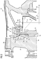
Fig. 2 illustrates in a sectional view a portion of theturbine section 18 of thegas turbine 10 illustrated inFig. 1 . Theturbine section 18 comprises anarrangement 60 for damping vibrations. Thearrangement 60 comprises arotor shaft 22, afirst rotor component 62 connected to the rotor, asecond rotor component 64 connected to the rotor and a dampingstructure 66 fixed at thefirst rotor component 62 or floated betweenfirst rotor component 62 and second one 64 and having acontact surface 68 arranged to press against acontact surface 70 of thesecond rotor component 64 to damp a vibration of thesecond rotor component 64. - In the illustrated embodiment, the
first rotor component 62 is formed by thedisk 36 which carries arotor blade 38, e.g. a third or fourth stage downstream the combustor or can be a disk that carries no blades. Further, in the presently illustrated embodiment, thesecond rotor component 64 is formed by a disk which does not carry rotor blades but which carriesplural teeth 72 which, together with a profile 74 at astator portion 76 form alabyrinth seal 78 to inhibit flow-through of a coolinggas 80. - The damping
structure 66 is designed to exert, during rotation of therotor shaft 22 at a predetermined rotational speed, a predetermined force F to thecontact surface 70 of thesecond rotor component 64. A tangent 69 taken on thecontact surface 68 of the dampingstructure 66 forms an angle α with the axial direction 82 (The radial direction is labelled with reference sign 83). The angle α may be between 30° and 75. Other values are possible. As can be appreciated fromFig. 2 , thecontact surface 68 of the dampingstructure 66 has a curved shape, in particular being convex, thecontact surface 70 of the second component having a concave shape. In other embodiments, the contact surface 68 (and also thecontact surface 70 of the second component) has a plane or planar shape. - The damping
structure 66 comprises a fixingsection 84 which allows for example to fix the dampingstructure 66 via a bolt 86 (or some other mechanism) to thefirst rotor component 62, i.e. thedisk 36. The radial position of the fixing section is r1 and the radial position of the (e.g. center of the)contact surface 68 of the dampingstructure 66 is r2, wherein r2 > r1. - The damping
structure 66 further comprises aspacer portion 88 between the fixingsection 84 and thecontact surface 68. By adjusting the length or by designing the length of thespacer portion 88, thecontact surface 68 of the dampingstructure 66 may advantageously be positioned to be in tight contact and to press against thecontact surface 70 of the second rotor component. - The damping
structure 66 has a radial extent sr and has an axial extent toward thesecond rotor component 64 sa, wherein sa < sr. Theteeth 72 are radially outward from thecontact surface 68 of the dampingstructure 66. - According to an embodiment of the present invention, the damping structure consists of a membrane (which also could be divided into segments). The membrane may be mounted (floated, bolted, hooked, etc.) behind the component having the vibrations to be damped. During engine operation, the membrane may be elongated (due to centrifugal force and due to thermal expansion) and the contact with the
disk 64 may be retained. Vibration of thedisk 64 results in a relative motion between thedisk 64 and themembrane 66. Due to a relative motion and friction between contact surfaces, damping will be introduced in the system which helps to reduce disk vibrations. It also adds additional stiffness to the critical location on disk which is favorable. - Embodiments of the present invention allow the possibility to solve vibration problems in engines with minimum modifications and changes to the engine. Even it allows to easily solve the problem in machines which are currently operating in the field.
- It should be noted that the term "comprising" does not exclude other elements or steps and "a" or "an" does not exclude a plurality. Also elements described in association with different embodiments may be combined. It should also be noted that reference signs in the claims should not be construed as limiting the scope of the claims.
Claims (14)
- Arrangement (60) for damping vibrations in a gas turbine (10), comprising:a rotor shaft (22) arranged for rotating;a first rotor component (62) connected to the rotor shaft (22);a second rotor component (64) connected to the rotor shaft (22);a damping structure (66) fixed at the first rotor component (62) or floated and having a contact surface (68) arranged to press against a contact surface (70) of the second rotor component (64) to damp a vibration of the second rotor component.
- Arrangement according to claim 1, wherein the damping structure (66) is designed to exert, during rotation of the rotor at a predetermined rotational speed, a predetermined force (F) to the contact surface (70) of the second rotor component (64), in order to damp primarily an axial vibration of the second rotor component (64),
the contact surface (70) of the second rotor component (64) in particular comprising a coating configured to reduce wear due to friction against the contact surface of the damping surface. - Arrangement according to claim 1 or 2, wherein the contact surface (70) of the second rotor component has an angle (α) against an axial direction between 30° and 75°, the contact surface (70) having in particular a curved shape,
wherein in particular the predetermined force has a predetermined direction. - Arrangement according to one of the preceding claims,
wherein the damping structure (66) comprises a fixing section (84) used to fix the damping structure (66) at the first rotor component (62), wherein the fixing section (84) of the damping structure (66) is located further radially inwards from the contact surface of the damping structure (66). - Arrangement according to the preceding claim,
wherein the damping structure (66) further comprises a spacer portion (88) between the fixing section (84) and the contact surface of the damping structure (66), the spacer portion (88) forming a ring plate. - Arrangement according to claim 4 or 5, wherein the fixing section (84) allows bolting the damping structure (66) to the first rotor component (62).
- Arrangement according to one of the preceding claims,
wherein the damping structure (66) extends to a larger degree radially than axially. - Arrangement according to one of the preceding claims,
wherein the damping structure (66) forms a ring, made from a single piece or comprising several segments that form a ring - Arrangement according to one of the preceding claims,
wherein the arrangement is part of a turbine section of the gas turbine (10),
wherein the first rotor component (62) is a disk (36) having rotor blades connected to it or wherein the first rotor component (62) is a shaft without connected rotor blades. - Arrangement according to the preceding claim,
wherein the second rotor component (64) comprises at a radially most outward section plural teeth (72) of a labyrinth seal (78) formed against a stator portion (76), the labyrinth seal intended to inhibit flow-through of a cooling gas (80). - Arrangement according to the preceding claim, wherein flow-through of the cooling gas (80) through the labyrinth seal (78) excites vibration of the second rotor component (64).
- Arrangement according to one of the preceding claims 10 or 11, wherein the contact portion (70) of the second rotor component (64) is radially inwards from the teeth (72).
- Gas turbine (10) comprising an arrangement (60) according to one of the preceding claims.
- Method for damping vibrations in a gas turbine (10), the method comprising:rotating a rotor shaft (22);exciting a vibration of a second rotor component (64) connected to the rotor shaft (22);pressing against a contact surface (70) of the second rotor component (64) using a contact surface (68) of a damping structure (66) fixed at a first rotor component (62) that is connected to the rotor shaft (22).
Priority Applications (2)
| Application Number | Priority Date | Filing Date | Title |
|---|---|---|---|
| EP16162147.9A EP3222811A1 (en) | 2016-03-24 | 2016-03-24 | Damping vibrations in a gas turbine |
| PCT/EP2017/053103 WO2017162365A1 (en) | 2016-03-24 | 2017-02-13 | Damping vibrations in a gas turbine |
Applications Claiming Priority (1)
| Application Number | Priority Date | Filing Date | Title |
|---|---|---|---|
| EP16162147.9A EP3222811A1 (en) | 2016-03-24 | 2016-03-24 | Damping vibrations in a gas turbine |
Publications (1)
| Publication Number | Publication Date |
|---|---|
| EP3222811A1 true EP3222811A1 (en) | 2017-09-27 |
Family
ID=55628871
Family Applications (1)
| Application Number | Title | Priority Date | Filing Date |
|---|---|---|---|
| EP16162147.9A Withdrawn EP3222811A1 (en) | 2016-03-24 | 2016-03-24 | Damping vibrations in a gas turbine |
Country Status (2)
| Country | Link |
|---|---|
| EP (1) | EP3222811A1 (en) |
| WO (1) | WO2017162365A1 (en) |
Cited By (2)
| Publication number | Priority date | Publication date | Assignee | Title |
|---|---|---|---|---|
| CN113606000A (en) * | 2021-07-28 | 2021-11-05 | 中国科学院工程热物理研究所 | Disc rotor system with vibration damping and weight reducing functions |
| CN114026311A (en) * | 2019-05-29 | 2022-02-08 | 赛峰飞机发动机公司 | Turbine assembly with damper |
Families Citing this family (1)
| Publication number | Priority date | Publication date | Assignee | Title |
|---|---|---|---|---|
| CN114109529B (en) * | 2021-11-30 | 2023-12-19 | 中国航发湖南动力机械研究所 | Spring-supported extrusion oil film metal rubber damper |
Citations (6)
| Publication number | Priority date | Publication date | Assignee | Title |
|---|---|---|---|---|
| US4361213A (en) | 1980-05-22 | 1982-11-30 | General Electric Company | Vibration damper ring |
| US5733103A (en) | 1996-12-17 | 1998-03-31 | General Electric Company | Vibration damper for a turbine engine |
| US6375428B1 (en) | 2000-08-10 | 2002-04-23 | The Boeing Company | Turbine blisk rim friction finger damper |
| EP1584785A1 (en) * | 2004-04-09 | 2005-10-12 | Snecma | Balancing weight for a rotor, especially for a rotor of a jet engine |
| EP1602855A2 (en) * | 2004-06-01 | 2005-12-07 | General Electric Company | Balancing assembly for turbine rotor |
| US20120207603A1 (en) * | 2009-06-16 | 2012-08-16 | General Electric Company | Trapped spring balance weight and rotor assembly |
Family Cites Families (3)
| Publication number | Priority date | Publication date | Assignee | Title |
|---|---|---|---|---|
| US3666376A (en) * | 1971-01-05 | 1972-05-30 | United Aircraft Corp | Turbine blade damper |
| US4101245A (en) * | 1976-12-27 | 1978-07-18 | United Technologies Corporation | Interblade damper and seal for turbomachinery rotor |
| US8066479B2 (en) * | 2010-04-05 | 2011-11-29 | Pratt & Whitney Rocketdyne, Inc. | Non-integral platform and damper for an airfoil |
-
2016
- 2016-03-24 EP EP16162147.9A patent/EP3222811A1/en not_active Withdrawn
-
2017
- 2017-02-13 WO PCT/EP2017/053103 patent/WO2017162365A1/en active Application Filing
Patent Citations (6)
| Publication number | Priority date | Publication date | Assignee | Title |
|---|---|---|---|---|
| US4361213A (en) | 1980-05-22 | 1982-11-30 | General Electric Company | Vibration damper ring |
| US5733103A (en) | 1996-12-17 | 1998-03-31 | General Electric Company | Vibration damper for a turbine engine |
| US6375428B1 (en) | 2000-08-10 | 2002-04-23 | The Boeing Company | Turbine blisk rim friction finger damper |
| EP1584785A1 (en) * | 2004-04-09 | 2005-10-12 | Snecma | Balancing weight for a rotor, especially for a rotor of a jet engine |
| EP1602855A2 (en) * | 2004-06-01 | 2005-12-07 | General Electric Company | Balancing assembly for turbine rotor |
| US20120207603A1 (en) * | 2009-06-16 | 2012-08-16 | General Electric Company | Trapped spring balance weight and rotor assembly |
Cited By (4)
| Publication number | Priority date | Publication date | Assignee | Title |
|---|---|---|---|---|
| CN114026311A (en) * | 2019-05-29 | 2022-02-08 | 赛峰飞机发动机公司 | Turbine assembly with damper |
| CN114026311B (en) * | 2019-05-29 | 2024-04-02 | 赛峰飞机发动机公司 | Turbine assembly with damper |
| CN113606000A (en) * | 2021-07-28 | 2021-11-05 | 中国科学院工程热物理研究所 | Disc rotor system with vibration damping and weight reducing functions |
| CN113606000B (en) * | 2021-07-28 | 2023-03-14 | 中国科学院工程热物理研究所 | Disc rotor system with vibration damping and weight reducing functions |
Also Published As
| Publication number | Publication date |
|---|---|
| WO2017162365A1 (en) | 2017-09-28 |
Similar Documents
| Publication | Publication Date | Title |
|---|---|---|
| CN109538352B (en) | Outer drum rotor assembly and gas turbine engine | |
| US5466123A (en) | Gas turbine engine turbine | |
| EP2071139B1 (en) | Bearing mounting system in a low pressure turbine | |
| US5215435A (en) | Angled cooling air bypass slots in honeycomb seals | |
| CN109723508B (en) | Structure for mitigating vibration modes of counter-rotating engine rotor | |
| CN109519224B (en) | Gas turbine engine including turbine rotor assembly | |
| JP5681384B2 (en) | Rotor blade for turbine engine | |
| US10961850B2 (en) | Rotatable torque frame for gas turbine engine | |
| JP2013151936A (en) | Retrofittable interstage angled seal | |
| JP2012233475A (en) | Centrifugal compressor assembly with stator vane row | |
| EP3141698A1 (en) | Arrangement for a gas turbine | |
| CA2786153C (en) | Damper seal and vane assembly for a gas turbine engine | |
| US9169737B2 (en) | Gas turbine engine rotor seal | |
| EP3222811A1 (en) | Damping vibrations in a gas turbine | |
| US9856740B2 (en) | Tip-controlled integrally bladed rotor for gas turbine engine | |
| US20180258781A1 (en) | Rim seal | |
| JP2012013084A (en) | Method and apparatus for assembling rotating machine | |
| US11629722B2 (en) | Impeller shroud frequency tuning rib | |
| US11788424B2 (en) | Sealing ring for a wheel of a turbomachine turbine | |
| US20230235680A1 (en) | Non-uniform turbomachinery blade tips for frequency tuning | |
| WO2022051760A1 (en) | Guide vane in gas turbine engine |
Legal Events
| Date | Code | Title | Description |
|---|---|---|---|
| PUAI | Public reference made under article 153(3) epc to a published international application that has entered the european phase |
Free format text: ORIGINAL CODE: 0009012 |
|
| AK | Designated contracting states |
Kind code of ref document: A1 Designated state(s): AL AT BE BG CH CY CZ DE DK EE ES FI FR GB GR HR HU IE IS IT LI LT LU LV MC MK MT NL NO PL PT RO RS SE SI SK SM TR |
|
| AX | Request for extension of the european patent |
Extension state: BA ME |
|
| STAA | Information on the status of an ep patent application or granted ep patent |
Free format text: STATUS: THE APPLICATION IS DEEMED TO BE WITHDRAWN |
|
| 18D | Application deemed to be withdrawn |
Effective date: 20180328 |