EP2276185A2 - Method and Apparatus for Spread Spectrum Radio Signal Recovery in Wideband Spread Spectrum Communication Systems - Google Patents
Method and Apparatus for Spread Spectrum Radio Signal Recovery in Wideband Spread Spectrum Communication Systems Download PDFInfo
- Publication number
- EP2276185A2 EP2276185A2 EP10182038A EP10182038A EP2276185A2 EP 2276185 A2 EP2276185 A2 EP 2276185A2 EP 10182038 A EP10182038 A EP 10182038A EP 10182038 A EP10182038 A EP 10182038A EP 2276185 A2 EP2276185 A2 EP 2276185A2
- Authority
- EP
- European Patent Office
- Prior art keywords
- signals
- frequency oscillator
- coupled
- signal recovery
- recovery circuit
- Prior art date
- Legal status (The legal status is an assumption and is not a legal conclusion. Google has not performed a legal analysis and makes no representation as to the accuracy of the status listed.)
- Withdrawn
Links
Images


Classifications
-
- H—ELECTRICITY
- H04—ELECTRIC COMMUNICATION TECHNIQUE
- H04B—TRANSMISSION
- H04B7/00—Radio transmission systems, i.e. using radiation field
- H04B7/14—Relay systems
- H04B7/15—Active relay systems
- H04B7/204—Multiple access
- H04B7/216—Code division or spread-spectrum multiple access [CDMA, SSMA]
-
- H—ELECTRICITY
- H04—ELECTRIC COMMUNICATION TECHNIQUE
- H04B—TRANSMISSION
- H04B1/00—Details of transmission systems, not covered by a single one of groups H04B3/00 - H04B13/00; Details of transmission systems not characterised by the medium used for transmission
- H04B1/69—Spread spectrum techniques
- H04B1/707—Spread spectrum techniques using direct sequence modulation
- H04B1/7097—Interference-related aspects
- H04B1/711—Interference-related aspects the interference being multi-path interference
- H04B1/7115—Constructive combining of multi-path signals, i.e. RAKE receivers
-
- H—ELECTRICITY
- H04—ELECTRIC COMMUNICATION TECHNIQUE
- H04L—TRANSMISSION OF DIGITAL INFORMATION, e.g. TELEGRAPHIC COMMUNICATION
- H04L25/00—Baseband systems
- H04L25/02—Details ; arrangements for supplying electrical power along data transmission lines
- H04L25/14—Channel dividing arrangements, i.e. in which a single bit stream is divided between several baseband channels and reassembled at the receiver
-
- H—ELECTRICITY
- H04—ELECTRIC COMMUNICATION TECHNIQUE
- H04B—TRANSMISSION
- H04B2201/00—Indexing scheme relating to details of transmission systems not covered by a single group of H04B3/00 - H04B13/00
- H04B2201/69—Orthogonal indexing scheme relating to spread spectrum techniques in general
- H04B2201/707—Orthogonal indexing scheme relating to spread spectrum techniques in general relating to direct sequence modulation
- H04B2201/70707—Efficiency-related aspects
Abstract
Description
- The present invention is generally related to wireless communication systems and, more particularly, is related to systems and methods for spread spectrum radio signal recovery.
- With the increasing availability of efficient, low cost electronic modules, mobile communication systems are becoming more and more widespread. For example, there are many variations of communication schemes in which various frequencies, transmission schemes, modulation techniques and communication protocols are used to provide two-way voice and data communications in a handheld telephone like communication handset. The different modulation and transmission schemes each have advantages and disadvantages.
- The next generation of wireless communication is referred to as 3G, which stands for third generation. 3G refers to pending improvements in wireless data and voice communications through a variety of proposed standards. One goal of 3G systems is to raise transmission speeds from 9.5 kilobits (Kbits) to 2 megabits (Mbits) per second. 3G also adds a mobile dimension to services that are becoming part of everyday life, such as Internet and intranet access, videoconferencing, and interactive application sharing. This advancement in wireless communication necessitates improvements in the area of spread spectrum radio signal recovery. One aspect of spread spectrum radio signal recovery is multipath signals, which are two or more identical signals from the same antenna reaching the receiver at different times due to taking different paths from the antenna to the receiver.
- European Patent Application No.
EP 0 813 313 A2 - International Publication No.
WO 00/18027 - US Patent No.
US 5,987,056 relates to spread spectrum wireless communications using pseudorandom noise sequences. - The present invention provides a method and system for spread spectrum radio signal recovery in wideband spread spectrum communication systems.
- Briefly described, one embodiment of the system comprises an antenna, a radio frequency subsystem, a baseband subsystem, and at least one peripheral device. The radio frequency subsystem is coupled to the antenna and includes a high frequency oscillator and a low frequency oscillator. The baseband subsystem is coupled to the radio frequency system and includes a free running counter coupled to the high frequency oscillator and the low frequency oscillator and a multipath signal recovery circuit coupled to the free running counter. The multipath signal recovery circuit includes a plurality of single path processors to recover clock information from a plurality of incoming signals.
- The peripheral device is coupled to the baseband subsystem to receive and supply signals to the baseband receiver.
- The present invention can also be viewed as providing a method of recovering spread spectrum radio signals. In this regard, one embodiment of such a method, can be broadly summarized as including the steps of recovering clock information from a plurality of signals from emitted from at least one basestation, aligning the plurality of signals using the recovered clock information, combining at least two of the aligned signals, and recovering information from the combined signal.
- Other systems, methods, features, and advantages of the present invention will be or become apparent to one with skill in the art upon examination of the following drawings and detailed description. It is intended that all such additional systems, methods, features, and advantages be included within this description and be within the scope of the present invention.
- Many aspects of the invention can be better understood with reference to the following drawings. The components in the drawings are not necessarily to scale, emphasis instead being placed upon clearly illustrating the principles of the present invention. Moreover, in the drawings, like reference numerals designate corresponding parts throughout the several views.
- FIG. 1
- is a block diagram illustrating of one embodiment of a third generation portable transceiver according to the present invention.
- FIG. 2
- is a block diagram of a free running counter in the WCDMA modem of
FIG. 1 . - FIG. 3
- is a block diagram of the WCDMA modem of
FIG. 1 including the multipath monitor and multipath radio signal recovery circuit. - FIG. 4
- is a flow diagram of one embodiment of a method of providing a mobile time reference.
- Having summarized various aspects of the present invention, reference will now be made in detail to the description of the invention as illustrated in the drawings. While the invention will be described in connection with these drawings, there is no intent to limit it to the embodiment or embodiments disclosed therein. On the contrary, the intent is to cover all alternatives, modifications and equivalents included within the scope of the invention as defined by the appended claims.
-
FIG. 1 is a block diagram illustrating a simplified 3Gportable transceiver 20. In one embodiment,portable transceiver 20 can be, for example but not limited to, a portable telecommunication handset such as a mobile cellular-type telephone.Portable transceiver 20 includes antenna 22 connected toradio frequency subsystem 24.RF subsystem 24 includesreceiver 26, receiver baseband analog processor (BAP) 28,transmitter 30,transmitter BAP 32, high frequency oscillator (which may be implemented as a temperature controlled crystal oscillator (TCXO)) 34, low frequency oscillator (which may be a 32 KHz crystal oscillator (CO)) 36, and transmitter/receiver switch 38. - Antenna 22 transmits signals to and receives signals from
switch 38 viaconnection 40. Switch 38 controls whether a transmit signal onconnection 42 fromtransmitter 30 is transferred to antenna 22 or whether a received signal from antenna 22 is supplied toreceiver 26 viaconnection 44.Receiver 26 receives and recovers transmitted analog information of a received signal and supplies a signal representing this information viaconnection 46 toreceiver BAP 28. ReceiverBAP 28 converts these analog signals to a digital signal at baseband frequency and transfers it viabus 48 tobaseband subsystem 50. -
Baseband subsystem 50 includes WCDMAmodem 52,microprocessor 54,memory 56, digital signal processor (DSP) 58, andperipheral interface 60 in communication viabus 62.Bus 62, although shown as a single bus, may be implemented using multiple busses connected as necessary among the subsystems withinbaseband system 50. WCDMAmodem 52,microprocessor 54,memory 56, and DSP 58 provide the signal timing, processing, and storage functions forportable transceiver 20.Memory 56 may include dual port ram shared bymicroprocessor 54 and DSP 58. -
Peripheral interface 60 provides connection tobaseband subsystem 50 for a variety of items. These items may include, but are not limited to, devices that are physically part ofportable transceiver 20, such asspeaker 62,display 64,keyboard 66, andmicrophone 68, and devices that would be externally connected toportable transceiver 20, such as personal computer (PC) 70,test system 72, andhost system 74. -
Speaker 62 and display 64 receive signals frombaseband subsystem 50 viaconnections keyboard 66 and microphone 68 supply signals tobaseband subsystem 50 viaconnections test system 72, andhost system 74 all receive signals from and transmit signals tobaseband subsystem 50 viaconnections -
Baseband subsystem 50 provides control signals toRF subsystem 24 viaconnection 90. Although shown as asingle connection 90, the control signals may originate fromWCDMA modem 52,microprocessor 54, or DSP 58, and are supplied to a variety of points withinRF subsystem 24. These points include, but are not limited to,receiver 26,receiver BAP 28,transmitter 30,transmitter BAP 32, TCXO 34, andswitch 38. -
WCDMA modem 52 receives the digital signal fromreceiver BAP 28 onbus 48 and provides a digital signal totransmitter BAP 32 onbus 92.Transmitter BAP 32 converts this digital signal to an analog signal at radio frequency for transmission onconnector 94 toreceiver 30.Receiver 30 generates the transmit signal which is provided to antenna 22 viaconnectors switch 38. The operation ofswitch 38 is controlled by a control signal frombaseband subsystem 50 viaconnection 90. -
TCXO 34 provides a clock toreceiver 26,transmitter 30, andWCDMA modem 52 viaconnectors CO 36 provides on connector 102 a 32 KHz clock toWCDMA modem 52. These two clocks are used byWCDMA modem 52 to create a mobile time reference. This mobile time reference is constantly running and has an accuracy of approximately 32 nanoseconds. - Referring now to
FIG. 2 , a portion ofWCDMA modem 52 is shown illustrating free running counter (FRC) 104 which generates the mobile time reference for use byportable transceiver 20.FRC 104 is provided with a clock signal from the TCXO online 100 and a clock signal from the CO online 102. The clock signal from the TCXO online 100 can be a 30.72 MHz, and the clock signal from the CO online 102 can be 32 KHz. -
FRC 104 includesTCXO circuit 106, phase locked loop (PLL) 108, counter 110,drift estimator 112, andcorrection circuit 114.TXCO circuit 106 using the 30.72 MHz clock generates the mobile time reference. The 32 KHz clock is phase locked to the 30.72 MHz clock for improvedperformance using PLL 108. Counter 110 counts the cycles of the 32 KHz clock.Drift estimator 112 provides on estimate of the drift of the 32 KHz clock for use bycorrection circuit 114. The estimate of drift includes both the drift and bias of the clock as provided by a Kalman estimation as known to those having ordinary skill in the art.FRC 104 operates in two time domains, 30.72 MHz or 32 KHz, depending on whether theportable transceiver 20 is in active mode or idle mode, respectively. - In active mode the portable transceiver is actively transmitting, receiving, processing, or looking for signals. During idle mode the portable transceiver powers down most of its circuits to conserve power. The CO is always on providing a continuous 32 KHz clock signal to
FRC 104, but the TCXO is turned off during idle mode. - Now referring to
FIG. 3 , a block diagram of the WCDMA modem is shown. - When the portable transceiver is in active mode,
FRC 104 provides the mobile time reference including clock-phase, chip-counter, and slot-counter onbus 150 toprimary sync searcher 116,secondary sync searcher 118,gold code searcher 120, and single-path processor (SPP)controller 122 as shown inFIG. 3 . A 10 millisecond radio frame is divided into 15 slots (slot-counter 0-14). Each slot includes 2,560 chips (chip counter 02,559). Each chip contains 8 ticks (clock-phase 0-7).FRC 104 also generates a frame counter (0-511) for the mobile time reference by counting the frames that occur within a 5.12 second period. Also, the drift estimate is continually updated when the portable transceiver is in active mode. - When transitioning into the idle mode, a sleep/awake control signal on
line 124 from the microprocessor toFRC 104 transitions to a low state.Counter 110 is reset and begins counting the rising edges of the 32 KHz clock signal. At the next rising edge of the 32 KHz clock after the sleep/awake control signal transitions to a low state, the current mobile time reference and drift estimate fromTXCO circuit 106 is provided tocorrection circuit 114. At this time the portable transceiver goes into idle mode. During each subsequent count,correction circuit 114 updates the mobile time reference using the count and the drift estimate. Thus, the mobile time reference and drift estimate is maintained during the idle mode. - When transitioning to the active mode, the sleep/awake control signal transitions to a high state. At the next rising edge of the 32 KHz clock, the updated mobile time reference maintained in
correction circuit 114 is provided toTCXO circuit 106 andFRC 104 begins providing the mobile time reference for the portable transceiver using the 30.72 MHz clock and the updated mobile time reference as a starting point. - The idle time may extend into a number of seconds, and the active time with no paging detected could be as long as 5 milliseconds. Maintaining the mobile time reference during idle mode allows the portable transmitter to quickly transition to an active state, which translates into a shorter duration in the active state, thus reducing power consumption and extending battery life. Maintaining the mobile time reference to a 32 nanosecond accuracy improves the efficiency of detecting, identifying, and monitoring the incoming multipath signals.
- The FRC provides a timing reference for the portable transceiver system and for acquiring the parameters required to recovery the multipath signals and operate a multipath signal receiver.
-
WCDMA modem 52 includesFRC 104,receiver equalizer 126,multipath monitor 128, and multipath radiosignal recovery circuit 130. The mobile time reference fromFRC 104 is provided to bothmultipath monitor 128, such as a code acquisition system, and multipath radiosignal recovery circuit 130, such as a RAKE receiver as known to those having ordinary skill in the art. The digital signal from the receiver BAP is provided toreceiver equalizer 126 and equalized prior to being provided onbus 144 tomultipath monitor 128 and multipath radiosignal recovery circuit 130. -
Multipath monitor 128 includesprimary sync searcher 116,secondary sync searcher 118, andgold code searcher 120, and provides information regarding these searches to the microprocessor. - In one embodiment, multipath radio
signal recovery circuit 130 includesSPP controller 122, twelveSPPs 132, twelve first-in first-out (FIFO)circuits 134, twelvephase correctors 136, deskewing and timing controller (DTC) 138, four maximal rate combiners (MRC) 140, and fourdemodulation units 142. -
SPP controller 122 maps up to twelve multipath signals toSPPs 132 and provides a start command onbus 146 to each of theSPPs 132. Each SPP recovers and tracks incoming clock information relative to a basestation, provides the clock information toDTC 138, and provides phase estimation for both single and multiple basestation antennas to thecorresponding phase corrector 136. The clock information provided toDTC 138 is in the same form as the mobile time reference having a clock-phase, a chipcounter, and a slot-counter. The mapped equalized signal is passed through eachSPP 132 to thecorresponding FIFO 134. EachFIFO 134 has a subperiod of 512 chips. Each radio frame includes 38,400 chips or seventy-five subperiods of 512 chips. -
DTC 138 using the clock information from each ofSPPs 132 provides a read address and read strobe signal frombus 148 to each SPP, which time aligns the outputs ofFIFOs 134 relative to one another. The operation ofDTC 138 is a complex PLL operation. The output of eachFIFO 134 is provided to thecorresponding phase corrector 136 which corrects the phase of the signal using the phase estimation provided by the correspondingSPP 132. The outputs of eachphase corrector 136 is mapped to one of the fourMRCs 140. EachMRC 140 combines the signals mapped to it to increase the strength of the signal. The strengthened signal from eachMRC 140 is provided to the correspondingdemodulation unit 142.Demodulation unit 142 recovers information from the signal on up to eight channels. Thirty-two different channels are provided for information recovery. - One of the benefits of the above recovery system is that the information is not recovered from the signals until the signals are aligned improving the efficiency of the recovery. Another benefit is that signals from either or both of the antennas from a basestation can be utilized and mapped to an SPP. Still another benefit is the ability to align the signals from asynchronous basestations.
- The present invention provides a method and wideband spread spectrum receiver that recovers multipath signal components from multiple asynchronous transmitters or colocated antennas utilizing diversity transmission. The receiver tracks multiple assigned multipath signals, possibly from multiple antennas, and aligns signal components at the chip rate of the spread spectrum system. Next, the receiver performs phase and channel correction at the chip rate, combines signal components from each transmitting antenna at the chip rate, removes multiple spreading codes in parallel, and removes orthogonal channelization codes in parallel. Then, the receiver performs macro diversity combining, processes diversity transmitted signals, and reduces signal quantization bandwidth to an optimal dynamic range that minimizes memory requirement for error correction decoding. The receiver reduces the memory and processing requirement needed for multiple received signal paths in the presence of diversity encoding at the transmitter, when it is required that the receiver operate over a plethora of spreading channelization codes that are utilized in 3G spread spectrum systems.
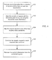
- Referring now to
FIG. 4 , one embodiment of the method of recovering spread spectrum radio signals is shown. Initially, clock information is recovered from a plurality of signals emitted from at least one basestation as shown inblock 200. Inblock 202, the plurality of signals are then aligned by the deskewing and timing unit using the recovered clock information. Each of the aligned signals are mapped to one of the four maximal ratio combiners inblock 204. As shown inblock 206, each maximal ratio combiner combines the signals mapped to it. Finally, symbol information is recovered from the combined signals inblock 208. Symbol information includes the other information from the received signals excluding the clock information. - The above described signal recovery system and method tracks and recovers dynamic clock information, and provides the information to a central source that creates the necessary arrangement to align the incoming signals.
- Although an exemplary embodiment of the present invention has been shown and described, it will be apparent to those of ordinary skill in the art that a number of changes, modifications, or alterations to the invention as described may be made, none of which depart from the scope of the present invention. All such changes, modifications, and alterations should therefore be seen as within the scope of the present invention.
Claims (14)
- A portable transceiver system (20) for a wireless communication system, comprising:an antenna (22);a radio frequency subsystem (24) coupled to the antenna (22) and including a high frequency oscillator (34) and a low frequency oscillator (36);a baseband subsystem (50) coupled to the radio frequency system (24) and including a free running counter (104) coupled to the high frequency oscillator (34) and the low frequency oscillator (36) and a multipath signal recovery circuit (130) coupled to the free running counter (104); andat least one peripheral device coupled to the baseband subsystem (50) to receive and supply signals to the baseband subsystem (50), the multipath signal recovery circuit (130) including a plurality of single path processors to recover clock information from a plurality of incoming signals.
- The system of claim 1, wherein the multipath signal recovery circuit (130) includes a single path processor controller (122) to map one of the incoming signals to each of the single path processors using the free running counter (104).
- The system of claim 1, wherein the multipath signal recovery circuit (130) includes a deskewing and timing controller (138) coupled to the single path processors (130) to align the incoming signals using the clock information.
- The system of claim 3, wherein the multipath signal recovery circuit (130) includes a phase corrector (136) coupled to each single path processor to correct the phase of the incoming signal after being aligned.
- The system of claim 4, wherein the multipath signal recovery circuit (130) includes at least one maximal ratio combiner coupled to all of the phase correctors to combine at least two of the signals outputted from the phase correctors (136).
- The system of claim 1, wherein the free running counter (104) provides a mobile time reference to the system (20) and has a wake mode and a sleep mode, during the wake mode the free running counter (104) uses the high frequency oscillator (34) to generate the mobile time reference, and during sleep mode the free running counter (104) uses the low frequency oscillator (36) to maintain the mobile time reference.
- The system of claim 6, wherein the high frequency oscillator (34) is a temperature controlled crystal oscillator, especially one providing a 30.72 MHz clock.
- The system of claim 6, wherein the low frequency oscillator (36) is a crystal oscillator, especially one providing a 32 KHz clock.
- The system of claim 6, wherein the mobile time reference has an accuracy of at least 32 nanoseconds.
- The system of claim 6, wherein the free running counter (104) includes a phase locked loop (108) coupling the low frequency oscillator (36) to the high frequency oscillator (34).
- The system of claim 6, wherein the free running counter (104) includes a drift estimator (112) for the low frequency oscillator (36).
- The system of at least one of claims 1 to 11, wherein the multipath signal recovery circuit (130) is designed and arranged to
recover clock information from the plurality of signals emitted from at least one basestation,
align the plurality of signals using the recovered clock information,
combine at least two of the aligned signals, and
recover symbol information from the combined signal. - A method of recovering spread spectrum radio signals in a wireless wideband spread spectrum communication system, comprising:recovering clock information from a plurality of signals emitted from at least one basestation;aligning the plurality of signals using the recovered clock information;combining at least two of the aligned signals; and
recovering symbol information from the combined signal. - The method of claim 13, wherein the method is performed by a multipath signal recovery circuit (130) of a portable transceiver system (20) for a wireless communication system according to at least one of claims 1 to 11.
Applications Claiming Priority (2)
| Application Number | Priority Date | Filing Date | Title |
|---|---|---|---|
| US27519201P | 2001-03-12 | 2001-03-12 | |
| EP02721357A EP1368916A4 (en) | 2001-03-12 | 2002-03-12 | Method and apparatus for spread spectrum radio signal recovery in wideband spread spectrum communication systems |
Related Parent Applications (1)
| Application Number | Title | Priority Date | Filing Date |
|---|---|---|---|
| EP02721357.8 Division | 2002-03-12 |
Publications (2)
| Publication Number | Publication Date |
|---|---|
| EP2276185A2 true EP2276185A2 (en) | 2011-01-19 |
| EP2276185A3 EP2276185A3 (en) | 2012-07-25 |
Family
ID=23051255
Family Applications (2)
| Application Number | Title | Priority Date | Filing Date |
|---|---|---|---|
| EP02721357A Ceased EP1368916A4 (en) | 2001-03-12 | 2002-03-12 | Method and apparatus for spread spectrum radio signal recovery in wideband spread spectrum communication systems |
| EP10182038A Withdrawn EP2276185A3 (en) | 2001-03-12 | 2002-03-12 | Method and Apparatus for Spread Spectrum Radio Signal Recovery in Wideband Spread Spectrum Communication Systems |
Family Applications Before (1)
| Application Number | Title | Priority Date | Filing Date |
|---|---|---|---|
| EP02721357A Ceased EP1368916A4 (en) | 2001-03-12 | 2002-03-12 | Method and apparatus for spread spectrum radio signal recovery in wideband spread spectrum communication systems |
Country Status (7)
| Country | Link |
|---|---|
| US (1) | US7095804B2 (en) |
| EP (2) | EP1368916A4 (en) |
| JP (2) | JP4365096B2 (en) |
| KR (1) | KR100858070B1 (en) |
| CN (1) | CN1630993B (en) |
| TW (1) | TW527793B (en) |
| WO (1) | WO2002073840A1 (en) |
Families Citing this family (4)
| Publication number | Priority date | Publication date | Assignee | Title |
|---|---|---|---|---|
| US7894507B2 (en) * | 2004-10-06 | 2011-02-22 | Broadcom Corporation | Method and system for HSDPA maximum ratio combination (MRC) and equalization switching |
| US8121065B2 (en) * | 2006-01-30 | 2012-02-21 | Marvell World Trade Ltd. | TDMA controller for a wireless communication system and method of operating same |
| CN109845146B (en) | 2016-10-26 | 2020-07-07 | 华为技术有限公司 | Method and receiver for receiving asynchronous clocked multiple transmitter data |
| CN107277914B (en) * | 2017-06-15 | 2018-06-29 | 深圳市晟碟半导体有限公司 | Equipment time synchronization control method and system in a kind of wireless mesh network |
Citations (3)
| Publication number | Priority date | Publication date | Assignee | Title |
|---|---|---|---|---|
| EP0813313A2 (en) | 1996-06-13 | 1997-12-17 | Matsushita Electric Industrial Co., Ltd. | Mobile communication receiving apparatus |
| US5987056A (en) | 1997-11-13 | 1999-11-16 | Lsi Logic Corporation | PN sequence hopping method and system |
| WO2000018027A1 (en) | 1998-09-18 | 2000-03-30 | Golden Bridge Technology, Inc. | Multi-clock matched filter for receiving signals with multipath |
Family Cites Families (17)
| Publication number | Priority date | Publication date | Assignee | Title |
|---|---|---|---|---|
| US5251210A (en) * | 1991-11-01 | 1993-10-05 | Ibm Corporation | Method and apparatus for transforming low bandwidth telecommunications channels into a high bandwidth telecommunication channel |
| JP3555252B2 (en) | 1995-06-30 | 2004-08-18 | 株式会社デンソー | Intermittent reception control device |
| US5687190A (en) * | 1995-10-20 | 1997-11-11 | Otc Telecom | Non-coherent direct sequence spread spectrum receiver for detecting bit/symbol chip sequences using threshold comparisons of chip sequence correlations |
| US6005886A (en) * | 1996-08-05 | 1999-12-21 | Digital Radio Communications Corp. | Synchronization-free spread-spectrum demodulator |
| US5943613A (en) * | 1996-11-07 | 1999-08-24 | Telefonaktiebolaget Lm Ericsson | Method and apparatus for reducing standby current in communications equipment |
| JPH10190568A (en) * | 1996-12-27 | 1998-07-21 | Matsushita Electric Ind Co Ltd | Radio receiving device |
| US6029061A (en) * | 1997-03-11 | 2000-02-22 | Lucent Technologies Inc. | Power saving scheme for a digital wireless communications terminal |
| JPH11127134A (en) * | 1997-10-23 | 1999-05-11 | Takatori Ikueikai:Kk | Signal receiver for ds-cdma cellular system |
| US6085104A (en) * | 1998-03-25 | 2000-07-04 | Sharp Laboratories Of America, Inc. | Pilot aided, time-varying finite impulse response, adaptive channel matching receiving system and method |
| US6088602A (en) * | 1998-03-27 | 2000-07-11 | Lsi Logic Corporation | High resolution frequency calibrator for sleep mode clock in wireless communications mobile station |
| US6212398B1 (en) * | 1998-12-03 | 2001-04-03 | Ericsson Inc. | Wireless telephone that rapidly reacquires a timing reference from a wireless network after a sleep mode |
| JP2000244351A (en) * | 1999-02-19 | 2000-09-08 | Fujitsu Ltd | Reception controller and method therefor |
| JP2000252859A (en) * | 1999-02-25 | 2000-09-14 | Kokusai Electric Co Ltd | Cdma radio terminal |
| EP1157474A1 (en) * | 1999-03-10 | 2001-11-28 | Nokia Mobile Phones Ltd. | Unsupervised adaptive chip separation filter for cdma terminal |
| JP2000278752A (en) * | 1999-03-24 | 2000-10-06 | Toshiba Corp | Mobile radio terminal |
| DE60043437D1 (en) * | 1999-06-14 | 2010-01-14 | Ericsson Inc | MULTI-MODEL WIRELESS SOUNDS WITH ADHESIVE CIRCUITS AND ASSOCIATED METHODS AND CIRCUITS |
| ATE450931T1 (en) * | 2000-06-30 | 2009-12-15 | Texas Instruments Inc | METHOD FOR MAINTAINING SYNCHRONIZATION OF A MOBILE TERMINAL DURING INACTIVE COMMUNICATION PERIOD |
-
2002
- 2002-03-12 CN CN028064852A patent/CN1630993B/en not_active Expired - Lifetime
- 2002-03-12 EP EP02721357A patent/EP1368916A4/en not_active Ceased
- 2002-03-12 EP EP10182038A patent/EP2276185A3/en not_active Withdrawn
- 2002-03-12 US US10/096,445 patent/US7095804B2/en not_active Expired - Lifetime
- 2002-03-12 WO PCT/US2002/007421 patent/WO2002073840A1/en active Application Filing
- 2002-03-12 TW TW091104542A patent/TW527793B/en not_active IP Right Cessation
- 2002-03-12 KR KR1020037011918A patent/KR100858070B1/en active IP Right Grant
- 2002-03-12 JP JP2002571600A patent/JP4365096B2/en not_active Expired - Lifetime
-
2008
- 2008-02-07 JP JP2008028116A patent/JP4741614B2/en not_active Expired - Lifetime
Patent Citations (3)
| Publication number | Priority date | Publication date | Assignee | Title |
|---|---|---|---|---|
| EP0813313A2 (en) | 1996-06-13 | 1997-12-17 | Matsushita Electric Industrial Co., Ltd. | Mobile communication receiving apparatus |
| US5987056A (en) | 1997-11-13 | 1999-11-16 | Lsi Logic Corporation | PN sequence hopping method and system |
| WO2000018027A1 (en) | 1998-09-18 | 2000-03-30 | Golden Bridge Technology, Inc. | Multi-clock matched filter for receiving signals with multipath |
Also Published As
| Publication number | Publication date |
|---|---|
| US7095804B2 (en) | 2006-08-22 |
| JP4365096B2 (en) | 2009-11-18 |
| EP1368916A1 (en) | 2003-12-10 |
| JP2008182721A (en) | 2008-08-07 |
| KR20040014465A (en) | 2004-02-14 |
| CN1630993B (en) | 2011-01-12 |
| JP4741614B2 (en) | 2011-08-03 |
| JP2004530329A (en) | 2004-09-30 |
| WO2002073840A1 (en) | 2002-09-19 |
| CN1630993A (en) | 2005-06-22 |
| US20020131482A1 (en) | 2002-09-19 |
| KR100858070B1 (en) | 2008-09-11 |
| TW527793B (en) | 2003-04-11 |
| EP2276185A3 (en) | 2012-07-25 |
| EP1368916A4 (en) | 2008-05-07 |
Similar Documents
| Publication | Publication Date | Title |
|---|---|---|
| US6889055B1 (en) | Technique for reducing average power consumption in a wireless communications device | |
| US6963626B1 (en) | Noise-reducing arrangement and method for signal processing | |
| US8473000B2 (en) | Communication device, integrated circuit and method therefor | |
| KR20050092084A (en) | A network of base stations(bss) and user equipments(ues) each provided with an enhanced rake structure | |
| JP4741614B2 (en) | Method and apparatus for spread spectrum radio signal restoration in a broadband spread spectrum communication system | |
| US7110725B2 (en) | Method and apparatus for multipath signal detection, identification, and monitoring for wideband code division multiple access systems | |
| EP1353450A1 (en) | Rake receiver | |
| EP1261144A1 (en) | Method and system for optimising the length of a search window | |
| JP2005333351A (en) | Receiver | |
| WO2002098009A1 (en) | Method and system for optimising the length of a search window | |
| JP2001186050A (en) | Reception terminal | |
| KR20020071280A (en) | Apparatus and method for controlling pll to receive quick paging message in mobile communication terminal | |
| JP2004349819A (en) | Radio communication card | |
| KR20000052223A (en) | Dynamic Signal Processing Method for lower Power Demodulation | |
| JP2002152175A (en) | Cdma system | |
| JPH11191898A (en) | Cdma communication system |
Legal Events
| Date | Code | Title | Description |
|---|---|---|---|
| PUAI | Public reference made under article 153(3) epc to a published international application that has entered the european phase |
Free format text: ORIGINAL CODE: 0009012 |
|
| AC | Divisional application: reference to earlier application |
Ref document number: 1368916 Country of ref document: EP Kind code of ref document: P |
|
| AK | Designated contracting states |
Kind code of ref document: A2 Designated state(s): AT BE CH CY DE DK ES FI FR GB GR IE IT LI LU MC NL PT SE TR |
|
| RIN1 | Information on inventor provided before grant (corrected) |
Inventor name: KENT, MARK |
|
| REG | Reference to a national code |
Ref country code: HK Ref legal event code: DE Ref document number: 1149653 Country of ref document: HK |
|
| PUAL | Search report despatched |
Free format text: ORIGINAL CODE: 0009013 |
|
| AK | Designated contracting states |
Kind code of ref document: A3 Designated state(s): AT BE CH CY DE DK ES FI FR GB GR IE IT LI LU MC NL PT SE TR |
|
| RIC1 | Information provided on ipc code assigned before grant |
Ipc: H04B 1/707 20110101ALI20120615BHEP Ipc: H04B 15/00 20060101AFI20120615BHEP Ipc: H04L 25/14 20060101ALI20120615BHEP Ipc: H04B 1/38 20060101ALI20120615BHEP Ipc: H04L 5/16 20060101ALI20120615BHEP Ipc: H04K 1/00 20060101ALI20120615BHEP Ipc: H04L 27/30 20060101ALI20120615BHEP Ipc: H04B 1/7115 20110101ALI20120615BHEP |
|
| STAA | Information on the status of an ep patent application or granted ep patent |
Free format text: STATUS: THE APPLICATION IS DEEMED TO BE WITHDRAWN |
|
| 18D | Application deemed to be withdrawn |
Effective date: 20130126 |