EP2276107A2 - Flache dual polarisierte Antenne mit Einzelspeisung und mehrfachem Rahmenelement - Google Patents
Flache dual polarisierte Antenne mit Einzelspeisung und mehrfachem Rahmenelement Download PDFInfo
- Publication number
- EP2276107A2 EP2276107A2 EP10167719A EP10167719A EP2276107A2 EP 2276107 A2 EP2276107 A2 EP 2276107A2 EP 10167719 A EP10167719 A EP 10167719A EP 10167719 A EP10167719 A EP 10167719A EP 2276107 A2 EP2276107 A2 EP 2276107A2
- Authority
- EP
- European Patent Office
- Prior art keywords
- antenna structure
- antenna
- planar
- loop
- rectangular
- Prior art date
- Legal status (The legal status is an assumption and is not a legal conclusion. Google has not performed a legal analysis and makes no representation as to the accuracy of the status listed.)
- Ceased
Links
Images


Classifications
-
- H—ELECTRICITY
- H01—ELECTRIC ELEMENTS
- H01Q—ANTENNAS, i.e. RADIO AERIALS
- H01Q7/00—Loop antennas with a substantially uniform current distribution around the loop and having a directional radiation pattern in a plane perpendicular to the plane of the loop
-
- H—ELECTRICITY
- H01—ELECTRIC ELEMENTS
- H01Q—ANTENNAS, i.e. RADIO AERIALS
- H01Q1/00—Details of, or arrangements associated with, antennas
- H01Q1/12—Supports; Mounting means
- H01Q1/22—Supports; Mounting means by structural association with other equipment or articles
- H01Q1/24—Supports; Mounting means by structural association with other equipment or articles with receiving set
- H01Q1/241—Supports; Mounting means by structural association with other equipment or articles with receiving set used in mobile communications, e.g. GSM
- H01Q1/242—Supports; Mounting means by structural association with other equipment or articles with receiving set used in mobile communications, e.g. GSM specially adapted for hand-held use
-
- H—ELECTRICITY
- H01—ELECTRIC ELEMENTS
- H01Q—ANTENNAS, i.e. RADIO AERIALS
- H01Q1/00—Details of, or arrangements associated with, antennas
- H01Q1/12—Supports; Mounting means
- H01Q1/22—Supports; Mounting means by structural association with other equipment or articles
- H01Q1/24—Supports; Mounting means by structural association with other equipment or articles with receiving set
- H01Q1/241—Supports; Mounting means by structural association with other equipment or articles with receiving set used in mobile communications, e.g. GSM
- H01Q1/246—Supports; Mounting means by structural association with other equipment or articles with receiving set used in mobile communications, e.g. GSM specially adapted for base stations
-
- H—ELECTRICITY
- H01—ELECTRIC ELEMENTS
- H01Q—ANTENNAS, i.e. RADIO AERIALS
- H01Q1/00—Details of, or arrangements associated with, antennas
- H01Q1/36—Structural form of radiating elements, e.g. cone, spiral, umbrella; Particular materials used therewith
- H01Q1/38—Structural form of radiating elements, e.g. cone, spiral, umbrella; Particular materials used therewith formed by a conductive layer on an insulating support
-
- H—ELECTRICITY
- H01—ELECTRIC ELEMENTS
- H01Q—ANTENNAS, i.e. RADIO AERIALS
- H01Q21/00—Antenna arrays or systems
- H01Q21/06—Arrays of individually energised antenna units similarly polarised and spaced apart
- H01Q21/20—Arrays of individually energised antenna units similarly polarised and spaced apart the units being spaced along or adjacent to a curvilinear path
- H01Q21/205—Arrays of individually energised antenna units similarly polarised and spaced apart the units being spaced along or adjacent to a curvilinear path providing an omnidirectional coverage
-
- H—ELECTRICITY
- H01—ELECTRIC ELEMENTS
- H01Q—ANTENNAS, i.e. RADIO AERIALS
- H01Q21/00—Antenna arrays or systems
- H01Q21/24—Combinations of antenna units polarised in different directions for transmitting or receiving circularly and elliptically polarised waves or waves linearly polarised in any direction
Definitions
- This disclosure relates to wireless communications and more specifically to the design and implementation of a dual-polarization planar antenna in a base station to enable polarization diversity.
- Polarization diversity improves wireless performance by enabling a wireless device to transmit a signal at multiple polarizations, because the polarization sensitivity of the distant end antenna may be unknown or uncontrolled. It may also be important to improve signal transmission and reception quality in wireless communication systems that have a multiplicity of radio frequency (RF) propagation problems.
- One way of improving polarization diversity is to achieve dual, orthogonal polarization sensitivity in an antenna.
- An example of a dual polarization antenna is a structure that can support simultaneous transmission or reception of both horizontally polarized and vertically polarized radiation of electromagnetic waves.
- Achieving dual polarization is often achieved by connecting each of multiple feeds to a different point on a single antenna structure, such that one feed excites currents that support one polarization, while a separate feed excites currents that support the orthogonal polarization.
- FIG. 1A illustrates a dual-polarization antenna in accordance with one embodiment of the present disclosure
- FIG. 1B illustrates a snapshot in time of one possible current distribution in the antenna of FIG. 1A according to one embodiment of the present disclosure
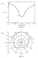
- FIG. 2 illustrates a plot of the return loss measured for the antenna illustrated in FIG 1A ;
- FIG. 3 is a XOZ plot of the radiation pattern at a wireless local area network (WLAN) frequency of the antenna illustrated in FIG. 1A ;
- WLAN wireless local area network
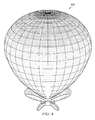
- FIG. 4 is a three dimensional view of the radiation pattern of the configuration of the antenna illustrated in FIG. 3 ;
- FIG. 5A is a configuration of another dual-polarization antenna according to another embodiment of the disclosure.
- FIG. 5B illustrates an exemplary current distribution at a specific point in time of the antenna illustrated in FIG. 5A ;
- FIG. 6A is another configuration of a dual-polarization antenna according to another embodiment of the disclosure.
- FIG. 6B illustrates an exemplary current distribution at a specific time of the antenna illustrated in FIG. 6A ;
- FIG. 7A illustrates another configuration of a dual-polarization antenna according to another embodiment of the disclosure
- FIG. 7B illustrates an exemplary current distribution at a specific point in time of the dual-polarization antenna illustrated in FIG. 7A ;
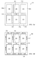
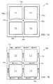
- FIG. 8A illustrates an array of antennas using the embodiment of the antenna illustrated in FIG. 5A ;
- FIG. 8B illustrates the array of antennas as depicted in FIG. 8A including the presence of a ground plane
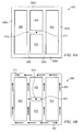
- FIG. 8C illustrates a folding of the array of antennas using the embodiment illustrated in FIG. 8A ;
- FIG. 8D is a diagram of the radiation directions based on the embodiment of the folded antenna illustrated in FIG. 8C ;
- FIG. 8E illustrates another embodiment of the folding of the array of antennas illustrated in FIG. 8A ;
- FIG. 9 illustrates a top level base transceiver system implementing the antenna of FIG. 8B according to one embodiment of the disclosure.
- the present disclosure provides a planar dual-polarization antenna comprised of microstrip elements placed end-to-end in the shape of a rectangular loop.
- the microstrip elements are conductive elements that may be formed from a thin film of metal, such as copper, gold, nichrome, and other such transmission line metals know to one skilled in the art. The thickness of the metal selected may be based on the application.
- a number of microstrip elements may be symmetrically oriented within the planar antenna to form an array of rectangular shaped loops. As used herein, "a number of" items refers to one or more items.
- the number of rectangular shaped loops formed by the microstrip elements within the antenna structure affects the antenna gain.
- a single feed is disposed at an interior point of the planar antenna.
- the interior point may be one specific interior point located at the center of the antenna structure.
- the single feed excites the plurality of rectangular shaped loops that are symmetrically oriented within the antenna structure.
- the antenna gain increases with the number of rectangular shaped loops formed by the microstrip elements.
- FIG. 1 and FIGS. 5 -7 discussed in detail later herein, provide embodiments of exemplary configurations of a dual-polarization planar antenna formed using a plurality of microstrip elements configured in an arrangement of rectangular loops. The increased number of microstrip elements in a horizontal and vertical directions increase
- the dual-polarization planar antenna 100 is comprised of contiguous microstrip elements 100a, 100b, 100c and 100d that are electrically connected to form strip loops 102, 104, 106, and 108.
- the dual polarization planar antenna 100 and the strip loops 102, 104, 106, and 108 may be rectangular-shaped.
- Microstrip elements 100a, 100b, 100c and 100d may be of a same width 116 .
- a single feed 118 disposed at one specific interior point of the antenna structure 100 may carry current that symmetrically excites strip loops 102, 104, 106, and 108.
- the single specific point may be located at the center of antenna structure 100. The center may be considered to be at a midpoint of the orthogonal x and y axes of antenna 100.
- the perimeter of the dual-polarization planar antenna 100 may be equal to a wavelength or one lambda at the operational frequency.
- each microstrip element is composed of four microstrip elements that are identical in length, each microstrip element being approximately one-quarter lambda in length.
- a number of additional planar microstrip elements may be placed within the perimeter of the antenna structure to form strip loops of various rectangular configurations. For example, in FIG. 1A , microstrip 100e is placed in the center of the antenna structure space 100. An additional microstrip element 100f results in a formation of strip loops 102 and 104.
- microstrip element 100g enables the formation of the strip loops 106 and 108 .
- the microstrip elements have the same width 116.
- Strip loops 102, 104, 106 and 108 may be formed by an arrangement or placement of microstrip elements of varying lengths and widths as may be recognized by one skilled in the art.
- microstrip element 100e may be comprised of two portions of a certain length that are conjoined. A first portion of microstrip element 100e may form a portion of strip loop 102 and a second portion of microstrip element 100e may form a portion of strip loop 104.
- the rectangular loops formed within the dual-polarization antenna 100 may be adjusted in size to obtain a particular antenna frequency and gain. In general, an increase in the number of loops within the antenna results in increased gain.
- a single feed point 118 physically connected to a coaxial cable may be used to source current that excites the microstrip radiating elements of rectangular loop structures 102, 104, 106, and 108 of antenna structure 100.
- FIG. 1B illustrates a snapshot in time of a simulated current distribution of the dual-polarization antenna 100 of FIG. 1A .
- the current distribution may run along the orthogonal x and y axes.
- the current is input from the coaxial cable feed point 118 and is distributed in a horizontal direction 124 and vertical direction 122. At a distance of one-half lambda the current may change direction as illustrated by current elements 126 and 128.
- graph 200 illustrates the return loss of the antenna measured at a base station receiver.
- the return loss plot 210 illustrates that the resident frequency of the antenna is within a wireless local area network (WLAN) band.
- the WLAN band ranges from between 2.45 gigahertz (GHz) and 5.56 GHz.
- the far-field radiation pattern measured for the antenna of FIG. 1A and FIG. 1B is illustrated at a resident frequency of 2.45 GHz.
- the radiation pattern 320 shows radiation directivity in the XZ plane.
- the radiation directivity of the radiation indicates the presence of a ground plane.
- radiation pattern 400 represents another view of the radiation pattern depicted in FIG. 3 .
- Radiation pattern 400 illustrates an exemplary three dimensional radiation pattern produced by the antenna depicted in FIG. 1A and FIG. 1B .
- Antenna 500 is configured as a 2 by 3 array of rectangular strip loops 506, 508, 510, 512, 514, and 516.
- the dual-polarization planar antenna 500 is comprised of contiguous microstrip elements 500a, 500b, 500c and 500d that are electrically connected to form a perimeter of rectangular shape.
- the perimeter of the dual-polarization planar antenna 500 may be equal to a wavelength or one lambda.
- a number of additional planar microstrip elements may be placed within the perimeter of the antenna structure to form strip loops of various rectangular configurations.
- the 2 by 3 array of rectangular strip loops 506, 508, 510, 512, 514, and 516 may be formed by the placement of horizontal microstrip element 500e and vertical microstrip elements 500f and 500g.
- the strip loops 506, 508, 510, 512, 514, and 516 formed by the placement of additional microstrip elements may be rectangular in shaped and identical in shape.
- a single feed 504 disposed at one specific interior point of the antenna structure 500 may carry current that symmetrically excites strip loops 506, 508, 510, 512, 514, and 516.
- the specified interior point may be located at a center of the antenna structure 500. The center may be considered as a midpoint of the orthogonal x and y axes of antenna structure 500.
- FIG. 5B illustrates a snapshot in time of a simulated current distribution of the dual-polarization antenna 500 of FIG. 5A .
- the current distribution may run along the orthogonal x and y axes.
- the current is input from the coaxial cable feed point 504 and is distributed in a horizontal direction 524 and vertical direction 522. At a distance of about one-half lambda the current may change direction as illustrated by current element 526 and 528.
- the dual-polarization planar antenna 600 is comprised of contiguous microstrip elements 600a, 600b, 600c and 600d that are electrically connected to form a perimeter of rectangular shape.
- the perimeter of the dual-polarization planar antenna 600 may be equal to a wavelength of one lambda.
- a number of additional planar microstrip elements may be placed within the perimeter of the antenna structure to form strip loops of various rectangular configurations.
- array of rectangular strip loops 606, 608, 610, and 612 may be formed by the placement of vertical microstrip elements 600e and 600f and horizontal microstrip element 600g.
- the strip loops 606 and 612 may be identical in shape.
- Strip loops 608 and 610 may also have an identical shape different from the strip loops 606 and 612.
- a single feed 614 disposed at one specific interior point of the antenna structure 600 may carry current that symmetrically excites strip loops 606, 608, 610, and 612.
- the specific interior point may be located at a center of the antenna structure 500. The center may be considered as a midpoint of the x and y axes of antenna structure 600.
- FIG. 6B illustrates a snapshot in time of a simulated current distribution of the dual-polarization antenna 600 of FIG. 6A .
- the current distribution may run along the orthogonal x and y axes.
- the current is input from the coaxial cable feed point 614 and is distributed in a horizontal direction 624 and vertical direction 622. At a distance of about one-half lambda the current may change direction as illustrated by current element 626 and 628.
- the dual-polarization planar antenna 700 is configured as a 2 by 2 array of contiguous microstrip elements 700a, 700b, 700c and 700d that are electrically connected to form a perimeter of rectangular shape.
- the perimeter of the dual-polarization planar antenna 700 may be equal to a wavelength of one lambda.
- a number of additional planar microstrip elements may be placed within the perimeter of the antenna structure to form strip loops of various rectangular configurations.
- the 2 by 2 array of rectangular strip loops 710, 712, 714, and 716 may be formed by the placement of horizontal microstrip element 700e and vertical microstrip element 700f.
- the strip loops 710, 712, 714, and 716 may be identical in shape.
- a single feed 704 disposed at one specific interior point of the antenna structure 700 may carry current that symmetrically excites strip loops 710, 712, 714, and 716.
- the specific interior point may be located at a center of the antenna structure 500. The center may be considered as a midpoint of the x and y axes of antenna structure 700.
- FIG. 7B illustrates a snapshot in time of a simulated current distribution of the dual-polarization antenna 700 of FIG. 7A .
- the current distribution may run along the orthogonal x and y axes.
- the current is input from the coaxial cable feed point 704 and is distributed in a horizontal direction 724 and vertical direction 722. At a distance of about one-half lambda the current may change direction as illustrated by current element 726 and 728.
- antenna structure 800 illustrates a formation of a number of identical dual-polarization planar antennas such as the dual-polarization planar antenna illustrated in FIG. 5A .
- planar antenna structure 800 is formed by the contiguous formation of antennas 810, 820, 830, 840 and 850 that are electrically connected.
- the perimeter of each planar antenna is equal to one lambda.
- Each planar antenna may be formed by the placement of microstrip elements of a same width, such as width 800w.
- antenna structure 800 may include a ground plane. It must be noted that antenna structure 800 may be comprised of structures of the same or differing configurations.
- a current may be carried to the structure through a single coaxial feed 804 disposed at one specific interior point of the structure.
- the single feed 804 may distribute current that symmetrically excites the strip loops of planar antennas 810, 820, 830, 840 and 850.
- the current distribution may be planar and run along orthogonal x and y axes as illustrated by current elements 812 and 814, respectively.
- the single specific interior point may be located at a center of the antenna structure 800.
- antenna structure 800 illustrates the dual-polarization planar antenna illustrated in FIG. 8A with a ground plane 890 according to one embodiment of the disclosure.
- the presence of the ground plane affects the antenna directivity.
- FIG. 8C illustrates a three dimensional antenna folded structure 860 of antenna structure 800 of FIG. 8A folded into the Z plane.
- planar antennas 820, 830, 840 and 850 may be folded downward in an orthogonal direction to X-Y plane for increased reception.
- the folded antenna structure 860 may have a radiation pattern that is omnidirectional.
- FIG. 8D illustrates an exemplary top level radiation pattern produced by three dimensional antenna structure 860.
- the radiation pattern is illustrated by radiating shapes represented as ovals 870, 872, 874, 876 and 878.
- FIG. 8E illustrates an exemplary three dimensional folded antenna structure 865 according to one embodiment of the disclosure.
- Antenna structure 865 represents a folded configuration of antenna structure 800 illustrated in FIG. 8A . It must be noted that antenna structure 865 is exemplary. Antenna structure 800 may be folded to implement a number of varying configurations.
- FIG. 9 illustrates a system 900 in which the three dimensional antenna structure, such as three dimensional antenna structure 930, may be implemented according to one embodiment of the disclosure.
- a radiating three dimensional structure 930 may be mounted to base transceiver station 910 through a coaxial cable feedline 920.
- radiating three dimensional structure 930 may represent a folded configuration of the antenna structure illustrated in FIG. 8B .
- Coaxial cable feedline 920 is represented as a dotted line because it cannot be directly viewed from the exterior of antenna structure 930 because of the interior ground plane.
- Coaxial cable feedline 920 provides a current feed to the three dimensional antenna structure 930 from a feedpoint at a center of the antenna structure 930.
- radiating three dimensional structure 930 may represent a folded configuration of the antenna structure illustrated in FIG. 8B . It must be noted that the radiating three dimensional structure 930 has a planar face in the x, y, and z directions. Therefore, antenna structure 930 may simultaneously receive signals being broadcast in the x, y, and z planes.
Applications Claiming Priority (1)
| Application Number | Priority Date | Filing Date | Title |
|---|---|---|---|
| US12/494,246 US8878737B2 (en) | 2009-06-29 | 2009-06-29 | Single feed planar dual-polarization multi-loop element antenna |
Publications (2)
| Publication Number | Publication Date |
|---|---|
| EP2276107A2 true EP2276107A2 (de) | 2011-01-19 |
| EP2276107A3 EP2276107A3 (de) | 2011-05-18 |
Family
ID=42671771
Family Applications (1)
| Application Number | Title | Priority Date | Filing Date |
|---|---|---|---|
| EP10167719A Ceased EP2276107A3 (de) | 2009-06-29 | 2010-06-29 | Flache dual polarisierte Antenne mit Einzelspeisung und mehrfachem Rahmenelement |
Country Status (3)
| Country | Link |
|---|---|
| US (1) | US8878737B2 (de) |
| EP (1) | EP2276107A3 (de) |
| CA (1) | CA2708731C (de) |
Cited By (2)
| Publication number | Priority date | Publication date | Assignee | Title |
|---|---|---|---|---|
| CN107925164A (zh) * | 2015-08-17 | 2018-04-17 | 日本电信电话株式会社 | 环形天线阵列以及环形天线阵列群 |
| CN112054289A (zh) * | 2020-09-07 | 2020-12-08 | 青岛海信移动通信技术股份有限公司 | 电子设备 |
Families Citing this family (13)
| Publication number | Priority date | Publication date | Assignee | Title |
|---|---|---|---|---|
| USD832782S1 (en) | 2015-12-30 | 2018-11-06 | Energous Corporation | Wireless charging device |
| USD773506S1 (en) | 2014-12-30 | 2016-12-06 | Energous Corporation | Display screen with graphical user interface |
| EP2787576A1 (de) * | 2013-04-03 | 2014-10-08 | Alcatel Lucent | Antennenanordnung zum Senden und/oder Empfangen von Hochfrequenzsignalen, Zugriffsnetzwerkknoten und Fahrzeug dafür |
| TWI560937B (en) * | 2013-11-22 | 2016-12-01 | Wistron Neweb Corp | Near field communication antenna |
| CN103730724B (zh) * | 2014-01-26 | 2017-01-11 | 广州天移通信科技发展有限公司 | 高隔离度、宽频带室内双极化全向吸顶天线 |
| USD805066S1 (en) | 2014-04-10 | 2017-12-12 | Energous Corporation | Laptop computer with antenna |
| USD784301S1 (en) | 2014-04-10 | 2017-04-18 | Energous Corporation | Monitor with antenna |
| USD786836S1 (en) * | 2014-04-10 | 2017-05-16 | Energous Corporation | Television with antenna |
| KR102257892B1 (ko) * | 2014-11-26 | 2021-05-28 | 삼성전자주식회사 | 개선된 nfc 안테나 및 그 안테나를 갖는 전자 장치 |
| US10454170B2 (en) | 2015-06-19 | 2019-10-22 | Koninklijke Philips N.V. | Multi-magnetic loop antenna with a single feed to parallel loops |
| USD832783S1 (en) | 2015-12-30 | 2018-11-06 | Energous Corporation | Wireless charging device |
| CN111682301B (zh) * | 2020-05-21 | 2021-04-30 | 电子科技大学 | 基于环状天线阵列的电磁飞环生成器 |
| CN112909582B (zh) * | 2021-01-21 | 2023-06-20 | 杭州永谐科技有限公司上海分公司 | 一种用于终端通信测试的宽带正交双极化全向天线及方法 |
Citations (4)
| Publication number | Priority date | Publication date | Assignee | Title |
|---|---|---|---|---|
| GB2074792A (en) * | 1980-04-23 | 1981-11-04 | Philips Nv | Thin-structure aerial |
| EP1033782A2 (de) * | 1999-03-02 | 2000-09-06 | Matsushita Electric Industrial Co., Ltd. | Monopolantenne |
| JP2007235682A (ja) * | 2006-03-02 | 2007-09-13 | Yagi Antenna Co Ltd | 平面アンテナ |
| US7511670B2 (en) | 2007-04-16 | 2009-03-31 | Research In Motion Limited | Dual-polarized, multiple strip-loop antenna, and associated methodology, for radio device |
Family Cites Families (17)
| Publication number | Priority date | Publication date | Assignee | Title |
|---|---|---|---|---|
| US3290688A (en) * | 1962-06-11 | 1966-12-06 | Univ Ohio State Res Found | Backward angle travelling wave wire mesh antenna array |
| FR2584872B1 (fr) * | 1985-07-09 | 1987-11-20 | Europ Agence Spatiale | Antenne plate a large bande a polarisation circulaire, utilisations d'une telle antenne, applications, et procede de fabrication |
| US5592182A (en) | 1995-07-10 | 1997-01-07 | Texas Instruments Incorporated | Efficient, dual-polarization, three-dimensionally omni-directional crossed-loop antenna with a planar base element |
| JPH09298413A (ja) | 1996-05-08 | 1997-11-18 | Harada Ind Co Ltd | 車載窓ガラスアンテナ装置 |
| JP3804878B2 (ja) | 1997-03-05 | 2006-08-02 | 日本電業工作株式会社 | 偏波共用アンテナ |
| US6160525A (en) * | 1999-01-28 | 2000-12-12 | Bae Systems Aerospace Inc. | Low impedance loop antennas |
| US6400337B1 (en) * | 2001-05-11 | 2002-06-04 | Dan Handelsman | Three dimensional polygon antennas |
| KR100467904B1 (ko) | 2001-12-04 | 2005-01-26 | 주식회사 에이스테크놀로지 | 스켈톤 슬롯 복사기 및 그를 이용한 다중대역 패치 안테나 |
| US6590542B1 (en) | 2001-12-17 | 2003-07-08 | James B. Briggs | Double loop antenna |
| JP2003243922A (ja) * | 2002-02-15 | 2003-08-29 | Toyota Central Res & Dev Lab Inc | アンテナ装置 |
| ES2314295T3 (es) | 2003-02-19 | 2009-03-16 | Fractus S.A. | Antena miniatura que tiene una estructura volumetrica. |
| FR2865329B1 (fr) | 2004-01-19 | 2006-04-21 | Pygmalyon | Dispositif recepteur-emetteur passif alimente par une onde electromagnetique |
| US7190317B2 (en) * | 2004-05-11 | 2007-03-13 | The Penn State Research Foundation | Frequency-agile beam scanning reconfigurable antenna |
| JP2006222848A (ja) * | 2005-02-14 | 2006-08-24 | Hitachi Cable Ltd | 円偏波アンテナ、アンテナ設計シミュレータ、及び同アンテナを備えた無線モジュール |
| US20070052590A1 (en) * | 2005-08-23 | 2007-03-08 | Tze-Hsuan Chang | Miniatured microstrip antenna |
| US7558555B2 (en) | 2005-11-17 | 2009-07-07 | Delphi Technologies, Inc. | Self-structuring subsystems for glass antenna |
| JP4870496B2 (ja) | 2006-08-11 | 2012-02-08 | マスプロ電工株式会社 | アンテナ |
-
2009
- 2009-06-29 US US12/494,246 patent/US8878737B2/en active Active
-
2010
- 2010-06-29 CA CA2708731A patent/CA2708731C/en active Active
- 2010-06-29 EP EP10167719A patent/EP2276107A3/de not_active Ceased
Patent Citations (4)
| Publication number | Priority date | Publication date | Assignee | Title |
|---|---|---|---|---|
| GB2074792A (en) * | 1980-04-23 | 1981-11-04 | Philips Nv | Thin-structure aerial |
| EP1033782A2 (de) * | 1999-03-02 | 2000-09-06 | Matsushita Electric Industrial Co., Ltd. | Monopolantenne |
| JP2007235682A (ja) * | 2006-03-02 | 2007-09-13 | Yagi Antenna Co Ltd | 平面アンテナ |
| US7511670B2 (en) | 2007-04-16 | 2009-03-31 | Research In Motion Limited | Dual-polarized, multiple strip-loop antenna, and associated methodology, for radio device |
Cited By (5)
| Publication number | Priority date | Publication date | Assignee | Title |
|---|---|---|---|---|
| CN107925164A (zh) * | 2015-08-17 | 2018-04-17 | 日本电信电话株式会社 | 环形天线阵列以及环形天线阵列群 |
| CN107925164B (zh) * | 2015-08-17 | 2020-08-21 | 日本电信电话株式会社 | 环形天线阵列群 |
| US10777909B2 (en) | 2015-08-17 | 2020-09-15 | Nippon Telegrah And Telephone Corporation | Loop antenna array and loop antenna array group |
| CN112054289A (zh) * | 2020-09-07 | 2020-12-08 | 青岛海信移动通信技术股份有限公司 | 电子设备 |
| CN112054289B (zh) * | 2020-09-07 | 2022-12-06 | 青岛海信移动通信技术股份有限公司 | 电子设备 |
Also Published As
| Publication number | Publication date |
|---|---|
| CA2708731C (en) | 2014-06-10 |
| EP2276107A3 (de) | 2011-05-18 |
| US8878737B2 (en) | 2014-11-04 |
| US20100328173A1 (en) | 2010-12-30 |
| CA2708731A1 (en) | 2010-12-29 |
Similar Documents
| Publication | Publication Date | Title |
|---|---|---|
| CA2708731C (en) | Single feed planar dual-polarization multi-loop element antenna | |
| CN112768894B (zh) | 具有交叉偶极子辐射元件的多频带基站天线 | |
| CA2708947C (en) | Compact single feed dual-polarized dual-frequency band microstrip antenna array | |
| CN110858679B (zh) | 具有宽带去耦辐射元件的多频带基站天线和相关辐射元件 | |
| US10720709B2 (en) | Self-grounded surface mountable bowtie antenna arrangement, an antenna petal and a fabrication method | |
| CN106688141B (zh) | 移动通信服务用全向天线 | |
| US8854270B2 (en) | Hybrid multi-antenna system and wireless communication apparatus using the same | |
| KR100895448B1 (ko) | 소형화된 mimo 안테나 | |
| US9287633B2 (en) | Dual frequency coupling feed antenna and adjustable wave beam module using the antenna | |
| EP2908380B1 (de) | Breitbandige doppelt polarisierte Patch-Antennenanordnung und Verfahren in Verbindung damit | |
| CN112956076A (zh) | 包括多谐振交叉偶极子辐射元件的天线和相关辐射元件 | |
| US10749272B2 (en) | Dual-polarized millimeter-wave antenna system applicable to 5G communications and mobile terminal | |
| US10978813B2 (en) | Bowtie antenna arrangement | |
| JP4952789B2 (ja) | 二偏波アンテナ | |
| EP3172797B1 (de) | Schlitzantenne | |
| JP2008236791A (ja) | 衛星及び地上システムの同時通信用アンテナシステム | |
| WO2012102576A2 (en) | Broad-band dual polarization dipole antenna and antenna array | |
| Breed | The fundamentals of patch antenna design and performance | |
| US20130106671A1 (en) | Multi-function feed network and antenna in communication system | |
| CN102576936A (zh) | 用于减少通信设备中的近场辐射和特殊吸收比率(sar)值的方法 | |
| CN113036400A (zh) | 辐射元件、天线组件和基站天线 | |
| KR101252244B1 (ko) | 다중 안테나 | |
| EP3685512B1 (de) | Antennensystem für drahtloskommunikationsvorrichtung | |
| KR20190087270A (ko) | 무선 통신 시스템에서 안테나 장치 및 이를 구비하는 전자기기 | |
| KR20090050566A (ko) | 차량 내 설치되는 mimo 시스템 |
Legal Events
| Date | Code | Title | Description |
|---|---|---|---|
| PUAI | Public reference made under article 153(3) epc to a published international application that has entered the european phase |
Free format text: ORIGINAL CODE: 0009012 |
|
| 17P | Request for examination filed |
Effective date: 20100629 |
|
| AK | Designated contracting states |
Kind code of ref document: A2 Designated state(s): AL AT BE BG CH CY CZ DE DK EE ES FI FR GB GR HR HU IE IS IT LI LT LU LV MC MK MT NL NO PL PT RO SE SI SK SM TR |
|
| AX | Request for extension of the european patent |
Extension state: BA ME RS |
|
| PUAL | Search report despatched |
Free format text: ORIGINAL CODE: 0009013 |
|
| AK | Designated contracting states |
Kind code of ref document: A3 Designated state(s): AL AT BE BG CH CY CZ DE DK EE ES FI FR GB GR HR HU IE IS IT LI LT LU LV MC MK MT NL NO PL PT RO SE SI SK SM TR |
|
| AX | Request for extension of the european patent |
Extension state: BA ME RS |
|
| 17Q | First examination report despatched |
Effective date: 20120209 |
|
| STAA | Information on the status of an ep patent application or granted ep patent |
Free format text: STATUS: THE APPLICATION HAS BEEN REFUSED |
|
| 18R | Application refused |
Effective date: 20130311 |