EP2275902A2 - Electronic device and method controlling electronic power supply - Google Patents
Electronic device and method controlling electronic power supply Download PDFInfo
- Publication number
- EP2275902A2 EP2275902A2 EP10168084A EP10168084A EP2275902A2 EP 2275902 A2 EP2275902 A2 EP 2275902A2 EP 10168084 A EP10168084 A EP 10168084A EP 10168084 A EP10168084 A EP 10168084A EP 2275902 A2 EP2275902 A2 EP 2275902A2
- Authority
- EP
- European Patent Office
- Prior art keywords
- charging
- unit
- electric power
- condition
- reading
- Prior art date
- Legal status (The legal status is an assumption and is not a legal conclusion. Google has not performed a legal analysis and makes no representation as to the accuracy of the status listed.)
- Withdrawn
Links
Images


Classifications
-
- H—ELECTRICITY
- H02—GENERATION; CONVERSION OR DISTRIBUTION OF ELECTRIC POWER
- H02J—ELECTRIC POWER NETWORKS; CIRCUIT ARRANGEMENTS OR SYSTEMS FOR SUPPLYING OR DISTRIBUTING ELECTRIC POWER; SYSTEMS FOR STORING ELECTRIC ENERGY
- H02J7/00—Circuit arrangements for charging or discharging batteries or for supplying loads from batteries
-
- G—PHYSICS
- G06—COMPUTING OR CALCULATING; COUNTING
- G06F—ELECTRIC DIGITAL DATA PROCESSING
- G06F1/00—Details not covered by groups G06F3/00 - G06F13/00 and G06F21/00
- G06F1/26—Power supply means, e.g. regulation thereof
- G06F1/263—Arrangements for using multiple switchable power supplies, e.g. battery and AC
-
- G—PHYSICS
- G06—COMPUTING OR CALCULATING; COUNTING
- G06F—ELECTRIC DIGITAL DATA PROCESSING
- G06F1/00—Details not covered by groups G06F3/00 - G06F13/00 and G06F21/00
- G06F1/26—Power supply means, e.g. regulation thereof
- G06F1/266—Arrangements to supply power to external peripherals either directly from the computer or under computer control, e.g. supply of power through the communication port, computer controlled power-strips
-
- G—PHYSICS
- G06—COMPUTING OR CALCULATING; COUNTING
- G06F—ELECTRIC DIGITAL DATA PROCESSING
- G06F1/00—Details not covered by groups G06F3/00 - G06F13/00 and G06F21/00
- G06F1/26—Power supply means, e.g. regulation thereof
- G06F1/32—Means for saving power
- G06F1/3203—Power management, i.e. event-based initiation of a power-saving mode
- G06F1/3206—Monitoring of events, devices or parameters that trigger a change in power modality
- G06F1/3212—Monitoring battery levels, e.g. power saving mode being initiated when battery voltage goes below a certain level
-
- Y—GENERAL TAGGING OF NEW TECHNOLOGICAL DEVELOPMENTS; GENERAL TAGGING OF CROSS-SECTIONAL TECHNOLOGIES SPANNING OVER SEVERAL SECTIONS OF THE IPC; TECHNICAL SUBJECTS COVERED BY FORMER USPC CROSS-REFERENCE ART COLLECTIONS [XRACs] AND DIGESTS
- Y02—TECHNOLOGIES OR APPLICATIONS FOR MITIGATION OR ADAPTATION AGAINST CLIMATE CHANGE
- Y02D—CLIMATE CHANGE MITIGATION TECHNOLOGIES IN INFORMATION AND COMMUNICATION TECHNOLOGIES [ICT], I.E. INFORMATION AND COMMUNICATION TECHNOLOGIES AIMING AT THE REDUCTION OF THEIR OWN ENERGY USE
- Y02D10/00—Energy efficient computing, e.g. low power processors, power management or thermal management
Definitions
- the present application relates to an electronic device, which is driven by a secondary battery (a chargeable battery), and a method controlling an electronic power supply for this electronic device.
- a secondary battery a chargeable battery
- Patent Document 1 Japanese Unexamined Patent Application, First Publication No. 2003-173822 (hereinafter referred to as Patent Document 1).
- the power feeding capacity of a USB is specified as a predetermined rating. Therefore, there is a problem in that an operation, which requires a large amount of electric power exceeding the predetermined rating, cannot be performed appropriately while the secondary battery is being charged via a USB cable. For example, operations such as the driving of a lens barrel cannot be performed appropriately while the secondary battery is being charged via a USB cable.
- an object of the present invention is to provide an electronic device which appropriately controls the charging operation of a secondary battery, as well as a method for controlling an electronic power supply.
- another object of the present invention is to provide a technology such that, while a secondary battery is being charged with an electric current at a predetermined rating, an operation which requires a large amount of electric current exceeding this predetermined rating can be executed appropriately.
- An electric device includes: a connecting unit connected to a connection line supplying an electric power of a predetermined rating and transmitting and receiving an information; a charging unit conducting a charging of a charging battery connected to an own device, by the electric power supplied by the connection line; an electric supplying unit supplying an electric power to a recording medium storing an information; a reading-and-writing unit performing a reading-and-writing operation of the recording medium; and an electronic source controlling unit performing a control of the electric power supplied to the charging unit, when the reading-and-writing unit performs the reading-and-writing operation of the recording medium, according to an access request to the recording medium via the connection line.
- an operation of charging a secondary battery, which drives an electronic device can be controlled appropriately.
- a method controlling an electronic power supply is a method of controlling an electronic power supply of an electronic device including a charging unit, a reading-and-writing unit, an electric source controlling unit, and an electric power supplying unit.
- the changing unit conducts a charging of a charging battery connected to an own device by an electric power supplied by a connection line supplying an electric power of a predetermined rating and transmitting and receiving an information.
- the reading-and-writing unit performs a reading-and-writing operation of a recording medium recording an information.
- the electronic source controlling unit performs a control of the electric power supplied to the charging unit, when the reading-and-writing unit performs the reading-and-writing operation of the recording medium recording the information.
- the power supplying unit supplies an electric power to the recording medium.
- the reading-and-writing unit performs a reading-and-writing operation of the recording medium.
- FIG. 1 is an overall structural diagram of a digital camera according to the present embodiment.
- a digital camera 100 includes an imaging lens 101, an image-capturing element 102, an A/D (Analog/Digital) converter 103, a CPU (Central Processing Unit) 104, a monitor 105, an image processing unit 106, a buffer memory 107, a flash ROM (Read Only Memory) 108, a recording medium I/F (Interface) 109, a recording medium 110, a power circuit 111, a charging type battery 112, a USB I/F 113, a bus 114, and a DCC (Direct Current Cable) 115.
- A/D Analog/Digital converter
- the digital camera 100 communicates with a host device 200 such as a PC or a printer via a USB cable 300. In addition, the digital camera 100 receives a supply of electricity from the host device 200.
- the A/D converter 103 converts an image of a subject, which is formed on the image-capturing element 102 through the imaging lens 101, into a digital signal.
- the CPU 104 executes a control of a sequence (the order of execution), an analysis of a PIP (Picture Transfer Protocol) command, and a control of the electric power supply.
- a sequence the order of execution
- PIP Packet Transfer Protocol
- the monitor 105 operates as a part of a user interface by displaying letters and image information such as an operation menu of the digital camera 100 and error messages, by displaying a warning, and by displaying information on a condition.
- the image processing unit 106 receives and displays a live view (real time) image, a confirmation image after photographing, and a photographed image stored in the recording medium 20.
- the live view image is obtained by performing a predetermined signal processing on a digital image signal obtained by the A/D converter 103.
- the buffer memory 107 stores a temporary data required for input and output.
- the flash ROM 108 records a firmware specifying a basic sequence for controlling the digital camera 100.
- the flash ROM 108 stores a digital image signal created by the A/D converter 103.
- the recording medium I/F 109 supplies electric current to the recording medium 110, and performs a reading-and-writing operation of the recording medium 110 according to a command by the CPU 104.
- the recording medium 110 is a memory card which is detachably attached to the digital camera 100.
- the recording medium 110 stores a digital image signal created by the A/D converter 103.
- the power circuit 111 charges the charging type battery 112, and supplies electric current to each processing unit of the digital camera 100. In addition, the power circuit 111 monitors the electric voltage between the terminals of the charging type battery 112, and determines whether the charging has been completed. The power circuit 111 also determines how much battery is remaining. Furthermore, based on a command from the CPU 104, the power circuit 111 controls the amount of electric current that is used to charge the charging type battery 112.
- the USB I/F 113 is connected to a USB cable.
- the USB I/F 113 receives a command and a supply of electric current from the host device 200.
- the maximum amount of the supply of electric current is 500mA.
- the bus 114 is a common pathway through which a signal is received and transmitted among each processing unit of the digital camera 100.
- the DCC 115 is a common pathway through which electric power is supplied to each processing unit of the digital camera 100.
- the power circuit 111 of the digital camera 100 charges the charging type battery 112 with an electric current supplied by the USB cable 300.
- the power circuit 111 controls the electric current supplied in order to charge the charging type battery 112
- the recording medium I/F 109 supplies electric current to the recording medium 110
- the recording medium I/F 109 performs a reading-and-writing operation on the recording medium 110 according to a command by the CPU
- the electric circuit controls the electric current supplied for charging the charging type battery 112.
- the power circuit 111 supplies electric current to the flash ROM 108.
- the CPU 104 perform the reading-and-writing operation of the flash ROM
- the charging operation with respect to the charging type battery 112 which drives the digital camera 100 is controlled appropriately.
- FIG. 2 is a flowchart representing an operation controlling a charging of a digital camera according to the above embodiment.
- the USB I/F 113 of the digital camera 100 is connected to the host device 200 via the USB cable 300 (step S1). Then, the CPU 104 outputs an instruction to transition to an energy saving mode (step S2). During this energy saving mode, the electric source of the image-capturing element 102, the A/D converter 103, the monitor 105, and the image processing unit 106 is turned off in order to increase the amount of electric current used for the charging operation.
- the power circuit 111 switches the electric source of the electric current supplied to the digital camera 100, to an electric current supplied from the host device 200 from the charging type battery 112 via the USB cable 300 (step S3).
- the CPU 104 determines whether there was an access request from the host device 200 via the USB I/F 113 (step S4).
- an access request refers to an access request for a reading-and-writing operation of the recording medium 110 or the flash ROM 108 of the digital camera 100 by the PTP command.
- the access request is outputted when the user operates the host device 200 and accesses the recording medium 110 or the flash ROM 108 of the digital camera 100 via the host device 200.
- step S4 NO
- the CPU 104 rewrites the charging condition information which is stored in the inner memory and indicates the condition of the charging type battery 112, to "high-speed charging condition" (step S5).
- the charging condition information is a value referring to either one of a "high-speed charging condition,” “low-Speed charging condition,” or “charging completed condition.”
- the "high-speed charging condition” is a condition in which an electric current other than the electric current necessary for the operation of the CPU 104, is allotted to the charging of the changing type battery 112. For example, when an electric current of 500mA is supplied from the USB cable 300, and an electric current of 100mA is necessary for the operation of the CPU 104, 400mA of electric current is allotted to the charging of the charging type battery 112.
- the "low-speed changing condition” refers to a condition in which an electric current, other than an electric current necessary for the operation of the CPU 104 and an electric current allotted to the operation of the flash ROM 108 or the recording medium 110, is allotted to the charging of the charging type battery 112.
- an electric current of 500mA is supplied from the USB cable 300
- an electric current of 100mA is necessary for the operation of the CPU 104
- the maximum value of the electric current of the electric source of the standard of the recording medium 110 is 200mA
- an electric current of 200mA is allotted to the charging of the charging type battery 112.
- the "charging completed condition” refers to a condition in which the charging of the charging type battery 112 is completed, and no electric current is allotted to the charging of the charging type battery 112.
- the CPU 104 When the CPU 104 has rewritten the charging condition information from “low-speed charging condition” to “high-speed charging condition,” the CPU 104 outputs to the electric current 111, a signal for changing the supply of the electric current to the charging type battery 112 to a "high-speed charging condition.”
- the CPU 104 when the CPU 104 has rewritten the charging condition information from “high-speed charging condition” to "low-speed charging condition,” the CPU 104 outputs to the power circuit 111, a signal for changing the supply of the electric current to the charging type battery 112 to a "low-speed charging condition.”
- the electric current 111 controls the amount of electric current supplied to the charging type battery 112 according to a signal which was inputted and received by the CPU 104.
- step S5 when the CPU 104 rewrites the charging condition information to the "high-speed charging condition," the CPU 104 determines whether or not the charging of the charging type battery 112 has been completed (step S6).
- the determination of whether the charging has been completed is conducted by the power circuit 111 outputting a signal notifying the CPU 104 that the charging has been completed when the charging of the charging type battery 112 is complete, and by the CPU 104 determining whether or not such a signal exists.
- step S6 NO
- the routine returns to step S4.
- the CPU 104 determines again whether or not there is an access request by the host device 200.
- step S6: YES A procedure conducted when the CPU 104 determines that the charging of the charging type battery 112 has been completed
- step S4 when a determination is made in step S4 that there is an access request from the host device 200 (step S4: YES), the CPU 104 rewrites the charging condition information, which is stored in the inner memory and indicates the condition of the charging type batter 112, to "low-speed changing condition " (step S7).
- the CPU 104 when the CPU 104 has rewritten the charging condition information from "high-speed charging condition” to "low-speed charging condition,” the CPU 104 outputs to the electric current 111, a signal for changing the supply of the electric current to the charging type battery 112, to the "low-speed charging condition.”
- an electric current of 500mA is supplied from the USB cable 300, an electric current of 100mA is necessary for operating the CPU 104, an electric current of 50mA is necessary for operating the flash ROM, and an electric current of 200mA is necessary to operate the recording medium 110.
- an electric current of 330mA is allotted to the charging of the charging type battery 112.
- an electric current of 200mA is allotted to the charging of the charging type battery 112.
- step S6 determines that the charging has been completed in step S6, step S8, and step S12 (step S6: YES, step S8: YES, step S12: YES)
- step S13 the CPU 104 rewrites the charging condition information stored in the inner memory to "charging completed condition" (step S 13).
- the power circuit 111 automatically stops supplying the electric current to the charging type battery 112.
- step S13 it is not necessary for the CPU 104 to output a signal to the electric current 111 for stopping the electric power supply to the charging type battery 112.
- the CPU 104 When the CPU 104 rewrites the charging condition information to the "charging completed condition," the CPU 104 waits for the reception of the access request from the host device 200 (step S14). Next, the CPU 104 determines whether or not there was an access request from the host device 200 (step S 15). When the CPU 104 determines that there is an access request (step S15: YES), the CPU 104 executes an access to the flash ROM 108 or the recording medium 110 (step S16). When the CPU 104 completes the access to the flash ROM 108 or the recording medium 110, the routine returns to step S14. Then, the CPU 104 waits again for a reception of an access request. In addition, when the CPU 104 completes the access to the flash ROM 108 or the recording medium 110, the CPU 104 deletes the time information recorded in the inner memory. THE CPU 104 also records the information on the elapsed time from this time.
- step S15 when the CPU 104 determines in step S15 that there is no access request from the host device 200 (step S15: NO), the CPU 104 refers to the time information recorded in the inner memory, and determines whether the time elapsed from the access completion time exceeds 30 minutes (step S17).
- the CPU 104 made a determination in step S6, step S8, and step S12 indicated in the flowchart shown in FIG. 2 whether or not the charging has been completed.
- the present invention is not limited to this configuration.
- a similar process may be executed by notifying the CPU 104 of the completion of the charging by cutting in a signal reporting the completion of the charging from the power circuit 111.
- the present embodiment of the present invention was applied to a digital camera was used in the above example.
- the present invention is not limited to this configuration.
- a similar effect may be achieved by applying the present invention to other electronic devices such as a portable phone or a music player.
- a case using a USB cable was described as a connecting wire which can supply an electric current of a predetermined rating and can transmit and receive information as well.
- the present invention is not limited to this configuration. It is possible to use other connection wires which enable the transmission and receiving of information as well as the supply of an electric current of a predetermined rating, such as a LAN (Local Area Network) cable.
- LAN Local Area Network
- the power circuit 111 reduced the maximum value of the electric current of the electric source of the standard of the recording medium 110 from the amount of electric power supplied to the charging type battery 112.
- the present invention is not limited by this configuration.
- the electric circuit 11 may reduce the necessary amount of electric current of the recording medium 110 from the amount of electric power supplied to the charging type battery 112.
- the electric current 111 may stop the supply of the electric current to the charging type battery 112.
- the present embodiment was described regarding a case in which the power circuit 111 controls the amount of electric current supplied to the charging type battery 112 when the recording medium 110 or the flash ROM 108 is accessed.
- the power circuit 111 may control the amount of electric voltage supplied to the charging type battery 112. For example, in further detail, when an electric voltage of 5V is supplied from the USB cable 300, IV of electric voltage is necessary to operate the CPU 104, and the maximum value of the electric voltage of the electric source of the standard of the recording medium 110 is 3.6V, and when the charging condition information is the "low-speed charging condition," the power circuit 111 may control the amount of electric voltage so that an electric voltage of 0.4V can be allotted for charging the charging type battery 112.
- the digital camera 100 includes a computer system in the interior.
- the operation of the CPU 104 is recorded in the flash ROM 108 in the form of a program.
- the above process is executed by the computer reading out this program and executing the program.
- this computer program may be transmitted to a computer via a transmission network, and the computer that has received this transmission may execute this program.
- the above program may be a program for executing a part of the feature described above.
- the above program may be a program that realizes the above feature by being executed in combination with another program which is already recorded in the computer system. This type of program is known as a difference file (difference program).
- FIG. 3A is a frontal perspective view when a lens barrel 2003 is being collapsed.
- FIG. 3B is a frontal perspective view when a lens barrel 2003 is protruding.
- FIG. 3C is a back side perspective view.
- a frontal surface of a camera body 2001 of a digital camera 2100 includes a lens barrel 2003, an ornamental ring 2004, a finder object window 2005, and a strobe window 2006.
- An opening-and-closing type lens barrier 2002 is provided on a frontal surface of the lens barrel 2003.
- a frontal surface of the ornamental ring 2004 is provided so as to be approximately on the same plane as a frontal surface of a front body of the camera body 2001.
- a front-most portion of the lens barrel 2003 is slightly receding from the frontal surface of the ornamental ring 2004, during a collapsed condition (a condition in which the lens barrel 2003 is stored inside the camera body 2001) in which the length in the direction of the optical axis is shorter than a photographing condition.
- the photographing condition refers to a condition during which a photograph is taken. In the collapsed condition, the lens barrier 2002 is closed, and a lens inside the lens barrel 2003 is protected (see FIG. 3A ).
- the lens barrier 2002 moves along with the initial driving, Thus, the lens barrier 2002 opens until the front-most surface of the lens barrel protrudes to the same plane as the front surface of the ornamental ring 2004.
- the lens barrier 2002 closes in combination with a final driving of the lens barrel 2003 when the lens barrel 2003 is driven to a collapsed condition from a position at which a normal photographing is made possible.
- the upper surface of the camera body 2001 includes a release button 2007 and a power source button 2008.
- the back surface of the camera body 2001 includes a monitor 2009, a finder ocular window 2010, an operating button 2011, and a sound reproduction unit (speaker) 2012.
- FIG. 4 is a functional configuration diagram of the digital camera 2100.
- the digital camera 2100 includes a lens barrel 2003, a monitor 2009, a strobe 2013, an imaging lens 2101, an image-capturing element 2102, anA/D (Analog/Digital) converter 2103, a CPU (Central Processing Unit) 2104, an image processing unit 2106, a buffer memory 2107, a flash ROM (Read Only Memory) 2108, a recording medium I/F (Interface) 2109, a recording medium 2110, a power circuit 2111, a charging type battery 2112, a USB I/F 2113, a bus 2114, a DCC (Direct Current Cable) 2115, and a barrel driving unit 2116.
- a lens barrel 2003 includes a lens barrel 2003, a monitor 2009, a strobe 2013, an imaging lens 2101, an image-capturing element 2102, anA/D (Analog/Digital) converter 2103, a CPU (Central Processing Unit) 2104, an image processing unit 2106,
- the USB I/F 2113 is connected to a USB cable 2300.
- the USB I/F 2113 receives a command and a supply of electric current of a predetermined rating (for instance, a maximum of 500mA) from a host device 2200 such as a PC and a printer, In other words, the digital camera 2100 communicates with the host device 2200 via the USB cable 2300.
- the digital camera 2100 also receives a supply of electric power from the host device 2200.
- the bus 2114 is a common pathway through which a signal is received and transmitted among each processing unit of the digital camera 2100.
- the DCC 2115 is a common pathway through which electric power is supplied to each processing unit of the digital camera 2100.
- the monitor 2009 provides a user interface.
- the monitor 2009 displays various information to the user by an electric current exceeding the predetermined standard and supplied by the charging type battery 2112 (hereinafter, referred to as an "electric current for display" for convenience).
- Examples of the displayed information includes an overall operation menu of the digital camera 2100, an operation menu regarding direct printing, various displays concerning conditions, and error messages.
- the monitor 2009 receives various inputs from the user.
- the strobe 2013 charges electric load to a condenser, discharges the charged electric load, and radiates the subject to be photographed.
- the strobe 2013 charges electric load to the condenser by an electric current exceeding the predetermined standard and provided by the charging type battery 2112 (hereinafter, referred to as an "electric current for charging the strobe" for convenience).
- the CPU 2104 controls the charging of the charging type battery 2112 by the power circuit 2111, as well as the supplying of the necessary electric current to each processing unit from the charging type battery 2112,
- the CPU 2104 makes the power circuit 2111 charge the charging type battery 2112 until the power circuit 2111 confirms that the electric current for driving the lens barrel can be supplied. Then, the CPU 2104 makes the power circuit 2111 supply the electric current for driving the lens barrel from the charging type battery 2112 to the barrel driving unit 2116.
- the CPU 2104 makes the power circuit 2111 recharge the charging type battery 2112.
- step S2003 the CPU 2104 determines whether or not the lens barrel 2003 has been collapsed into the camera body 2001 (step S2003). In other words, the CPU 2104 determines whether or not the lens barrel 2003 is in a collapsed condition (step S2003). For instance, the CPU 2104 transmits to the barrel driving unit 2116, a command to determine the condition of the lens barrel 2003. When the CPU 2104 receives a response from the barrel driving unit 2116 to this command indicating a determination result that the lens barrel 2003 is in a collapsed condition, the CPU 2104 determines that the lens barrel 2003 is already collapsed inside the camera body 2001. When the CPU 2104 determines that the lens barrel 2003 is already collapsed inside the camera body 2001 (step S2003: YES), the routine proceeds to step S2008, skipping steps S2004 through S2007.
- step S2004 determines that the charging type battery 2112 has been charged by an amount greater than a predetermined amount (step S2004: YES)
- the CPU 2104 makes the power circuit 2111 supply the current for driving the lens barrel from the charging type battery 2112 to the barrel driving unit 2116 (step S2005)
- the power circuit 2111 follows the command from the CPU 2104 and switches the power source of the electric current supplied to each processing unit from an electric current supplied by the host device 2200 via the USB cable 2300 to the charging type battery 2112.
- the power circuit 2111 supplies the electric current for driving the lens barrel from the charging type battery 2112 to the barrel driving unit 2116 (step S2005).
- the power circuit 2111 stops the charging of the charging type battery 2112, and begins to supply the electric current for driving the lens barrel from the charging type battery 2112 to the barrel driving unit 2116.
- the lens barrel 2003 of which is in a photographing condition the charging type battery 2112 is charged gradually.
- the lens barrel 2003 transitions from the photographing condition to the collapsed condition according to the electric current supplied by the charging type battery 2112.
- the predetermined condition of the digital camera 2100 may be a strobe charging completion condition in which the charging of the strobe 2013 has been completed.
- the electric current for charging the strobe which exceeds a predetermined standard, is necessary as described above.
- the CPU 2104 determines whether or not the strobe charging completion condition is reached, which is a predetermined condition in which the electric current for charging the strobe is necessary.
- the electric current for charging the strobe is a necessary amount of electric current exceeding the predetermined standard.
- the CPU 2104 makes the power circuit 2111 charge the charging type battery 2112 until the power circuit 2111 confirms that an electric current exceeding the predetermined amount can be supplied. Then, the CPU 2104 may make the power circuit 2111 supply the predetermined amount of electric current from the charging type battery 2112 to the strobe 2013.
- the amount of electric current supplied from the charging type battery 2112 which has almost completed the charging process may be set as the above predetermined amount.
- the amount of electric current supplied from the charging type battery 2112 which has almost completed the charging process may be set as the above predetermined amount.
- the predetermined condition of the digital camera 2100 in a situation in which the USB cable 2300 is connected to the USB I/F 2113 may be a display completion condition, which is a condition in which a predetermined content is displayed according to a demand by the monitor 2009. Further, in order for the display completion condition is reached, an electric current for display exceeding a predetermined standard is necessary, as described above. In addition, the CPU 2104 determines whether or not the display completion condition is reached, The display completion condition is a predetermined condition in which the electric current for displaying is needed. The electric current for displaying is a necessary amount of electric current exceeding a predetermined standard.
- the strobe 2013 may be charged as well. Therefore, at least when the charging of the charging type battery 2112 has been completed, it is possible to immediately use the strobe 2013.
- the charging type battery 2112 is being charged via the USB cable 2300, for instance, electric current is supplied to the monitor 2009. As a result, it is possible to conduct an operation such as direct print via the monitor 2009.
- the CPU 2104 may control the electric voltage.
- the power feeding cable according to the present invention is not limited to a USB cable,
- a connecting wire such as a LAN (Local Area Network) cable, which can supply an electric current of a predetermined standard, may be used.
- LAN Local Area Network
- connection wire which can simply supply an electric current of a predetermined standard.
- the above program may be a program for executing a part of the feature described above.
- the above program may be a program that realizes the above feature by being executed in combination with another program which is already recorded in the computer system. This type of program is known as a difference file (difference program).
Landscapes
- Engineering & Computer Science (AREA)
- Theoretical Computer Science (AREA)
- General Engineering & Computer Science (AREA)
- Physics & Mathematics (AREA)
- General Physics & Mathematics (AREA)
- Power Engineering (AREA)
- Computer Hardware Design (AREA)
- Studio Devices (AREA)
- Charge And Discharge Circuits For Batteries Or The Like (AREA)
Abstract
Description
- The present application relates to an electronic device, which is driven by a secondary battery (a chargeable battery), and a method controlling an electronic power supply for this electronic device.
- Conventionally, a technology is known which charges a secondary battery, which is embedded in an electronic device such as a digital camera, through a USB (Universal Serial Bus) cable. See, for example, Japanese Unexamined Patent Application, First Publication No.
2003-173822 - However, there is a limit on the amount of electric current provided from an external host device via a USB cable. This limit is based on a USB specification. Therefore, depending on the operation mode of digital cameras and the like, there is a problem in that the operation of charging a secondary battery cannot be controlled in an appropriate manner.
- In addition, the power feeding capacity of a USB is specified as a predetermined rating. Therefore, there is a problem in that an operation, which requires a large amount of electric power exceeding the predetermined rating, cannot be performed appropriately while the secondary battery is being charged via a USB cable. For example, operations such as the driving of a lens barrel cannot be performed appropriately while the secondary battery is being charged via a USB cable.
- The present invention is made considering the problems described above. Accordingly, an object of the present invention is to provide an electronic device which appropriately controls the charging operation of a secondary battery, as well as a method for controlling an electronic power supply.
- In addition, another object of the present invention is to provide a technology such that, while a secondary battery is being charged with an electric current at a predetermined rating, an operation which requires a large amount of electric current exceeding this predetermined rating can be executed appropriately.
- An electric device according to an aspect of the present invention includes: a connecting unit connected to a connection line supplying an electric power of a predetermined rating and transmitting and receiving an information; a charging unit conducting a charging of a charging battery connected to an own device, by the electric power supplied by the connection line; an electric supplying unit supplying an electric power to a recording medium storing an information; a reading-and-writing unit performing a reading-and-writing operation of the recording medium; and an electronic source controlling unit performing a control of the electric power supplied to the charging unit, when the reading-and-writing unit performs the reading-and-writing operation of the recording medium, according to an access request to the recording medium via the connection line.
- Based on the above electronic device according to an aspect of the present invention, an operation of charging a secondary battery, which drives an electronic device, can be controlled appropriately.
- A method controlling an electronic power supply according to an aspect of the present invention is a method of controlling an electronic power supply of an electronic device including a charging unit, a reading-and-writing unit, an electric source controlling unit, and an electric power supplying unit. Here, the changing unit conducts a charging of a charging battery connected to an own device by an electric power supplied by a connection line supplying an electric power of a predetermined rating and transmitting and receiving an information. In addition, the reading-and-writing unit performs a reading-and-writing operation of a recording medium recording an information. Further, the electronic source controlling unit performs a control of the electric power supplied to the charging unit, when the reading-and-writing unit performs the reading-and-writing operation of the recording medium recording the information. Moreover, the power supplying unit supplies an electric power to the recording medium. In addition, the reading-and-writing unit performs a reading-and-writing operation of the recording medium.
- Based on the above method controlling the electronic power supply according to an aspect of the present invention, it is possible to appropriately perform an operation which requires a large amount of electric current exceeding a predetermined rating, while a secondary battery is being charged with an electric current at the predetermined rating.
-
-
FIG. 1 is an overall configuration diagram of a digital camera according to a first embodiment of the present invention. -
FIG. 2 is a flowchart representing an operation controlling a charging of a digital camera according to the above embodiment. -
FIG. 3A is an overall diagram of a digital camera according to a second embodiment of the present invention. -
FIG. 3B is an overall diagram of a digital camera according to the above embodiment. -
FIG. 3C is an overall diagram of a digital camera according to the above embodiment. -
FIG. 4 is a functional structural diagram of a digital camera according to the above embodiment. -
FIG. 5 is a flowchart representing an operation while charging a digital camera according to the above embodiment. - Hereunder, an electronic device and a method controlling an electronic power supply according to an aspect of the present invention are described.
- The following explanation aims to provide a detailed explanation in order to facilitate the understanding of the gist of the present invention. Therefore, the following explanation does not limit the present invention in any way, except as specifically noted.
- Hereunder, a first embodiment of the present invention is described with reference to the diagrams.
-
FIG. 1 is an overall structural diagram of a digital camera according to the present embodiment. - A
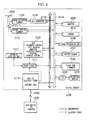
digital camera 100 includes animaging lens 101, an image-capturingelement 102, an A/D (Analog/Digital)converter 103, a CPU (Central Processing Unit) 104, amonitor 105, animage processing unit 106, abuffer memory 107, a flash ROM (Read Only Memory) 108, a recording medium I/F (Interface) 109, arecording medium 110, apower circuit 111, acharging type battery 112, a USB I/F 113, abus 114, and a DCC (Direct Current Cable) 115. - In addition, the
digital camera 100 communicates with ahost device 200 such as a PC or a printer via aUSB cable 300. In addition, thedigital camera 100 receives a supply of electricity from thehost device 200. - The A/
D converter 103 converts an image of a subject, which is formed on the image-capturingelement 102 through theimaging lens 101, into a digital signal. - The
CPU 104 executes a control of a sequence (the order of execution), an analysis of a PIP (Picture Transfer Protocol) command, and a control of the electric power supply. - The
monitor 105 operates as a part of a user interface by displaying letters and image information such as an operation menu of thedigital camera 100 and error messages, by displaying a warning, and by displaying information on a condition. - The
image processing unit 106 receives and displays a live view (real time) image, a confirmation image after photographing, and a photographed image stored in the recording medium 20. The live view image is obtained by performing a predetermined signal processing on a digital image signal obtained by the A/D converter 103. - The
buffer memory 107 stores a temporary data required for input and output. - The
flash ROM 108 records a firmware specifying a basic sequence for controlling thedigital camera 100. In addition, theflash ROM 108 stores a digital image signal created by the A/D converter 103. - The recording medium I/
F 109 supplies electric current to therecording medium 110, and performs a reading-and-writing operation of therecording medium 110 according to a command by theCPU 104. - The
recording medium 110 is a memory card which is detachably attached to thedigital camera 100. Therecording medium 110 stores a digital image signal created by the A/D converter 103. - The
power circuit 111 charges thecharging type battery 112, and supplies electric current to each processing unit of thedigital camera 100. In addition, thepower circuit 111 monitors the electric voltage between the terminals of thecharging type battery 112, and determines whether the charging has been completed. Thepower circuit 111 also determines how much battery is remaining. Furthermore, based on a command from theCPU 104, thepower circuit 111 controls the amount of electric current that is used to charge thecharging type battery 112. - The USB I/
F 113 is connected to a USB cable. The USB I/F 113 receives a command and a supply of electric current from thehost device 200. The maximum amount of the supply of electric current is 500mA. - The
bus 114 is a common pathway through which a signal is received and transmitted among each processing unit of thedigital camera 100. - The
DCC 115 is a common pathway through which electric power is supplied to each processing unit of thedigital camera 100. - According to the above configuration, the
power circuit 111 of thedigital camera 100 charges thecharging type battery 112 with an electric current supplied by theUSB cable 300. In addition, when therecording medium 110 is read and written based on an access request for information via theUSB cable 300, thepower circuit 111 controls the electric current supplied in order to charge the chargingtype battery 112, the recording medium I/F 109 supplies electric current to therecording medium 110, and the recording medium I/F 109 performs a reading-and-writing operation on therecording medium 110 according to a command by the CPU, In addition, when the reading-and-writing operation is performed on theflash ROM 108 based on an access request for information via theUSB cable 300, the electric circuit controls the electric current supplied for charging the chargingtype battery 112. Further, thepower circuit 111 supplies electric current to theflash ROM 108. In addition, theCPU 104 perform the reading-and-writing operation of the flash ROM, - According to the configurations described above, the charging operation with respect to the
charging type battery 112 which drives thedigital camera 100, is controlled appropriately. - Next, an operation controlling a charging of the
digital camera 100 is described. -
FIG. 2 is a flowchart representing an operation controlling a charging of a digital camera according to the above embodiment. - First, the USB I/
F 113 of thedigital camera 100 is connected to thehost device 200 via the USB cable 300 (step S1). Then, theCPU 104 outputs an instruction to transition to an energy saving mode (step S2). During this energy saving mode, the electric source of the image-capturingelement 102, the A/D converter 103, themonitor 105, and theimage processing unit 106 is turned off in order to increase the amount of electric current used for the charging operation. - Next, the
power circuit 111 switches the electric source of the electric current supplied to thedigital camera 100, to an electric current supplied from thehost device 200 from the chargingtype battery 112 via the USB cable 300 (step S3). When thepower circuit 111 switches the electric source, theCPU 104 determines whether there was an access request from thehost device 200 via the USB I/F 113 (step S4). Here, an access request refers to an access request for a reading-and-writing operation of therecording medium 110 or theflash ROM 108 of thedigital camera 100 by the PTP command. Incidentally, the access request is outputted when the user operates thehost device 200 and accesses therecording medium 110 or theflash ROM 108 of thedigital camera 100 via thehost device 200. - When the
CPU 104 determines that there was not any access request from the host device 200 (step S4: NO), theCPU 104 rewrites the charging condition information which is stored in the inner memory and indicates the condition of the chargingtype battery 112, to "high-speed charging condition" (step S5). - The charging condition information is a value referring to either one of a "high-speed charging condition," "low-Speed charging condition," or "charging completed condition." The "high-speed charging condition" is a condition in which an electric current other than the electric current necessary for the operation of the
CPU 104, is allotted to the charging of the changingtype battery 112. For example, when an electric current of 500mA is supplied from theUSB cable 300, and an electric current of 100mA is necessary for the operation of theCPU 104, 400mA of electric current is allotted to the charging of the chargingtype battery 112. - Meanwhile, the "low-speed changing condition" refers to a condition in which an electric current, other than an electric current necessary for the operation of the
CPU 104 and an electric current allotted to the operation of theflash ROM 108 or therecording medium 110, is allotted to the charging of the chargingtype battery 112. For example, when an electric current of 500mA is supplied from theUSB cable 300, an electric current of 100mA is necessary for the operation of theCPU 104, and the maximum value of the electric current of the electric source of the standard of therecording medium 110 is 200mA, an electric current of 200mA is allotted to the charging of the chargingtype battery 112. - Further, the "charging completed condition" refers to a condition in which the charging of the charging
type battery 112 is completed, and no electric current is allotted to the charging of the chargingtype battery 112. - When the
CPU 104 has rewritten the charging condition information from "low-speed charging condition" to "high-speed charging condition," theCPU 104 outputs to the electric current 111, a signal for changing the supply of the electric current to thecharging type battery 112 to a "high-speed charging condition." On the other hand, when theCPU 104 has rewritten the charging condition information from "high-speed charging condition" to "low-speed charging condition," theCPU 104 outputs to thepower circuit 111, a signal for changing the supply of the electric current to thecharging type battery 112 to a "low-speed charging condition," The electric current 111 controls the amount of electric current supplied to thecharging type battery 112 according to a signal which was inputted and received by theCPU 104. - In step S5, when the
CPU 104 rewrites the charging condition information to the "high-speed charging condition," theCPU 104 determines whether or not the charging of the chargingtype battery 112 has been completed (step S6). The determination of whether the charging has been completed is conducted by thepower circuit 111 outputting a signal notifying theCPU 104 that the charging has been completed when the charging of the chargingtype battery 112 is complete, and by theCPU 104 determining whether or not such a signal exists. - When the
CPU 104 determines that the charging of the chargingtype battery 112 has not been completed (step S6: NO), the routine returns to step S4. Here, theCPU 104 determines again whether or not there is an access request by thehost device 200. A procedure conducted when theCPU 104 determines that the charging of the chargingtype battery 112 has been completed (step S6: YES), is described later. - Meanwhile, when a determination is made in step S4 that there is an access request from the host device 200 (step S4: YES), the
CPU 104 rewrites the charging condition information, which is stored in the inner memory and indicates the condition of thecharging type batter 112, to "low-speed changing condition " (step S7). At this time, when theCPU 104 has rewritten the charging condition information from "high-speed charging condition" to "low-speed charging condition," theCPU 104 outputs to the electric current 111, a signal for changing the supply of the electric current to thecharging type battery 112, to the "low-speed charging condition." - In addition, it is possible to change the amount of electric current supplied to the
charging type battery 112 depending on whether the access request is an access request to theflash ROM 108 or an access request to therecording medium 110. In more detail, the following control may be executed. - Suppose that an electric current of 500mA is supplied from the
USB cable 300, an electric current of 100mA is necessary for operating theCPU 104, an electric current of 50mA is necessary for operating the flash ROM, and an electric current of 200mA is necessary to operate therecording medium 110. In this case, when the access request is an access request to theflash ROM 108, an electric current of 330mA is allotted to the charging of the chargingtype battery 112. On the other hand, when the access request is an access request to therecording medium 110, an electric current of 200mA is allotted to the charging of the chargingtype battery 112. - By executing the control described above, it is possible to more appropriately allot the electric current for charging the charging
type battery 112. - In step S7, when the charging condition information is rewritten to the "high-speed charging condition," the
CPU 104 determines whether or not the charging of the chargingtype battery 112 has been completed (step S8). When theCPU 104 determines that the charging of the chargingtype battery 112 has not been completed (step S8: NO), theCPU 104 executes an access to theflash ROM 108 or the recording medium 110 (step S9). In addition, when the access to theflash ROM 108 or therecording medium 110 has been completed, theCPU 104 begins to measure the time that has elapsed from the time at which the access has been completed. Here, theCPU 104 records the information on the measured time to the inner memory. - When the access to the
flash ROM 108 or to therecording medium 110 has been completed, theCPU 104 again determines whether or not there is an access request from the host device 200 (step S10). When theCPU 104 determines that there was an access request from the host device 200 (step S10; YES), the routine returns to step S8. Then, it is determined whether or not the charging has been completed, and the access is executed again. - On the other hand, when the
CPU 104 determines that there was not an access request from the host device 200 (step S10: NO), theCPU 104 refers to the timing information stored in the inner memory, and determines whether or not the time elapsed from the time at which the access was completed exceeds one minute (step S11). When theCPU 104 determines that the elapsed time has not reached one minute (step S11: NO), theCPU 104 determines whether or not the charging of the chargingtype battery 112 has been completed (step S12). When theCPU 104 determines that the charging has not been completed (step S12: NO), the routine returns to step S10. Once again, it is determined whether or not there is an access request from thehost device 200. - In addition, in step S11, when the
CPU 104 determines that one minute has elapsed (step S11: YES), theCPU 104 moves the process to step S5, and rewrites the charging condition information to "high-speed charging condition." In other words, when there is no access request within a predetermined amount of time since the access to theflash ROM 108 or therecording medium 110 has been completed, theCPU 104 changes the amount of decide current supplied to the charging type battery to an amount of electric current corresponding to the "high-speed charging condition." In this way, the number of times that the condition is transitioned between the "high-speed charging condition" and the "low-spoed charging condition" can be reduced. In addition, it is possible to mitigate the burden on thecharging type battery 112 due to the frequent increase and decrease in the amount of electric current that is supplied. - Furthermore, when the
CPU 104 determines that the charging has been completed in step S6, step S8, and step S12 (step S6: YES, step S8: YES, step S12: YES), theCPU 104 rewrites the charging condition information stored in the inner memory to "charging completed condition" (step S 13). Incidentally when it is determined that the charging has been completed, thepower circuit 111 automatically stops supplying the electric current to thecharging type battery 112. As a result, in step S13, it is not necessary for theCPU 104 to output a signal to the electric current 111 for stopping the electric power supply to thecharging type battery 112. In addition, when theCPU 104 rewrites the charging condition information to the "charging completed condition," theCPU 104 begins to measure the time that has elapsed since the charging condition information was thus rewritten to the "charging completed condition." At this time, theCPU 104 records the information on the measured time to the inner memory. - When the
CPU 104 rewrites the charging condition information to the "charging completed condition," theCPU 104 waits for the reception of the access request from the host device 200 (step S14). Next, theCPU 104 determines whether or not there was an access request from the host device 200 (step S 15). When theCPU 104 determines that there is an access request (step S15: YES), theCPU 104 executes an access to theflash ROM 108 or the recording medium 110 (step S16). When theCPU 104 completes the access to theflash ROM 108 or therecording medium 110, the routine returns to step S14. Then, theCPU 104 waits again for a reception of an access request. In addition, when theCPU 104 completes the access to theflash ROM 108 or therecording medium 110, theCPU 104 deletes the time information recorded in the inner memory. THECPU 104 also records the information on the elapsed time from this time. - On the other hand, when the
CPU 104 determines in step S15 that there is no access request from the host device 200 (step S15: NO), theCPU 104 refers to the time information recorded in the inner memory, and determines whether the time elapsed from the access completion time exceeds 30 minutes (step S17). - After the
CPU 104 determines that the elapsed time from the access completion time has not reached 30 minutes (step S11: NO), the routine returns to step S14, and waits again for a reception of an access request. On the other hand, when theCPU 104 determines that 30 minutes have elapsed from the access completion time (step S11: YES), theCPU 104 turns off the electric source of the digital camera 100 (step S18). As a result, it is possible to reduce the amount of electric current supplied to thehost device 200 when there is no access to thedigital camera 100. - In this way, according to the present embodiment, when there is no access request from the
host device 200 during the charging of the chargingtype battery 112, an electric current other than the electric current necessary for operating theCPU 104 is allotted to the charging of the chargingtype battery 112. Meanwhile, when there is an access request from thehost device 200 during the charging of the chargingtype battery 112, the amount of electric current supplied for the access to theflash ROM 108 or therecording medium 110 is reduced from the amount of electric current supplied to thecharging type battery 112. As a result, it is possible to appropriately control the charging operation with respect to thecharging type battery 112 which drives thedigital camera 100. - Heretofore, the first embodiment of the present invention has been described in detail in reference to the diagrams. The concrete configuration is not limited to the examples described above. Various modifications and the like may be made within the gist of the present invention.
- For instance, in the present embodiment, the
CPU 104 made a determination in step S6, step S8, and step S12 indicated in the flowchart shown inFIG. 2 whether or not the charging has been completed. However, the present invention is not limited to this configuration. A similar process may be executed by notifying theCPU 104 of the completion of the charging by cutting in a signal reporting the completion of the charging from thepower circuit 111. - In addition, an example in which the present embodiment of the present invention was applied to a digital camera was used in the above example. However, the present invention is not limited to this configuration. For instance, a similar effect may be achieved by applying the present invention to other electronic devices such as a portable phone or a music player.
- Further, in the present embodiment, a case using a USB cable was described as a connecting wire which can supply an electric current of a predetermined rating and can transmit and receive information as well. However, the present invention is not limited to this configuration. It is possible to use other connection wires which enable the transmission and receiving of information as well as the supply of an electric current of a predetermined rating, such as a LAN (Local Area Network) cable.
- In addition, in the present embodiment, an example was described in which, when the charging condition information was rewritten to the "low-speed charging condition" by accessing the
recording medium 110, thepower circuit 111 reduced the maximum value of the electric current of the electric source of the standard of therecording medium 110 from the amount of electric power supplied to thecharging type battery 112. However, the present invention is not limited by this configuration. For example, when theCPU 104 can obtain the necessary amount of electric current of therecording medium 110, the electric circuit 11 may reduce the necessary amount of electric current of therecording medium 110 from the amount of electric power supplied to thecharging type battery 112. - In addition, when the charging condition information is rewritten to the "low-speed charging condition," for example, the electric current 111 may stop the supply of the electric current to the
charging type battery 112. - Incidentally, the present embodiment was described regarding a case in which the
power circuit 111 controls the amount of electric current supplied to thecharging type battery 112 when therecording medium 110 or theflash ROM 108 is accessed. - However, the present invention is not limited to this configuration. The
power circuit 111 may control the amount of electric voltage supplied to thecharging type battery 112. For example, in further detail, when an electric voltage of 5V is supplied from theUSB cable 300, IV of electric voltage is necessary to operate theCPU 104, and the maximum value of the electric voltage of the electric source of the standard of therecording medium 110 is 3.6V, and when the charging condition information is the "low-speed charging condition," thepower circuit 111 may control the amount of electric voltage so that an electric voltage of 0.4V can be allotted for charging the chargingtype battery 112. - The
digital camera 100 includes a computer system in the interior. In addition, the operation of theCPU 104 is recorded in theflash ROM 108 in the form of a program. The above process is executed by the computer reading out this program and executing the program. In addition, this computer program may be transmitted to a computer via a transmission network, and the computer that has received this transmission may execute this program. - Furthermore, the above program may be a program for executing a part of the feature described above. Moreover, the above program may be a program that realizes the above feature by being executed in combination with another program which is already recorded in the computer system. This type of program is known as a difference file (difference program).
- Hereunder, a second embodiment of the present invention is described in detail with reference to the diagrams.
-
FIG. 3A is a frontal perspective view when alens barrel 2003 is being collapsed.FIG. 3B is a frontal perspective view when alens barrel 2003 is protruding.FIG. 3C is a back side perspective view. - As indicated in
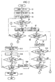
FIGS. 3A and 3B , a frontal surface of acamera body 2001 of adigital camera 2100 includes alens barrel 2003, anornamental ring 2004, afinder object window 2005, and astrobe window 2006. An opening-and-closingtype lens barrier 2002 is provided on a frontal surface of thelens barrel 2003. A frontal surface of theornamental ring 2004 is provided so as to be approximately on the same plane as a frontal surface of a front body of thecamera body 2001. A front-most portion of thelens barrel 2003 is slightly receding from the frontal surface of theornamental ring 2004, during a collapsed condition (a condition in which thelens barrel 2003 is stored inside the camera body 2001) in which the length in the direction of the optical axis is shorter than a photographing condition. The photographing condition refers to a condition during which a photograph is taken. In the collapsed condition, thelens barrier 2002 is closed, and a lens inside thelens barrel 2003 is protected (seeFIG. 3A ). When thelens barrel 2003 is protruded from the collapsed condition to a position at which a normal photographing is made possible, thelens barrier 2002 moves along with the initial driving, Thus, thelens barrier 2002 opens until the front-most surface of the lens barrel protrudes to the same plane as the front surface of theornamental ring 2004. In addition, thelens barrier 2002 closes in combination with a final driving of thelens barrel 2003 when thelens barrel 2003 is driven to a collapsed condition from a position at which a normal photographing is made possible. In addition, the upper surface of thecamera body 2001 includes arelease button 2007 and apower source button 2008. As shown inFIG. 3C , the back surface of thecamera body 2001 includes amonitor 2009, a finderocular window 2010, anoperating button 2011, and a sound reproduction unit (speaker) 2012. -
FIG. 4 is a functional configuration diagram of thedigital camera 2100. Thedigital camera 2100 includes alens barrel 2003, amonitor 2009, astrobe 2013, animaging lens 2101, an image-capturingelement 2102, anA/D (Analog/Digital)converter 2103, a CPU (Central Processing Unit) 2104, animage processing unit 2106, abuffer memory 2107, a flash ROM (Read Only Memory) 2108, a recording medium I/F (Interface) 2109, a recording medium 2110, apower circuit 2111, a chargingtype battery 2112, a USB I/F 2113, abus 2114, a DCC (Direct Current Cable) 2115, and abarrel driving unit 2116. - The USB I/
F 2113 is connected to aUSB cable 2300. The USB I/F 2113 receives a command and a supply of electric current of a predetermined rating (for instance, a maximum of 500mA) from ahost device 2200 such as a PC and a printer, In other words, thedigital camera 2100 communicates with thehost device 2200 via theUSB cable 2300. Thedigital camera 2100 also receives a supply of electric power from thehost device 2200. Thebus 2114 is a common pathway through which a signal is received and transmitted among each processing unit of thedigital camera 2100. TheDCC 2115 is a common pathway through which electric power is supplied to each processing unit of thedigital camera 2100. - The
power circuit 2111 charges the chargingtype battery 2112 with an electric current supplied by theUSB cable 2300. In addition, thepower circuit 2111 supplies electric current from the chargingtype battery 2112 to each processing unit of thedigital camera 2100. Thepower circuit 2111 monitors the electric voltage between the terminals of the chargingtype battery 2112, and verifies the amount of charging made to thecharging type battery 2112. - The A/
D converter 2103 converts an image of the subject, which is formed on the image-capturingelement 2102 through theimaging lens 2101, into a digital signal. Theimage processing unit 2106 receives and displays a live view (real time) image, a confirmation image after photographing, and a photographed image stored in the recording medium 2110. The live view image is obtained by performing a predetermined signal processing on a digital image signal obtained by the A/D converter 2103. - The
barrel driving unit 2116 includes a motor. Thebarrel driving unit 2116 changes the condition of thelens barrel 2003. In detail, thebarrel driving unit 2116, for instance, makes a transition between the photographing condition and the collapsed condition by an electric current exceeding the above predetermined standard and provided from the charging type battery 2112 (hereinafter, referred to as a "electric current for driving the lens barrel" for convenience). In addition, thebarrel driving unit 2116 includes, for example, a photo interrupter, and determines whether or not thelens barrel 2003 is in a collapsed condition. - Incidentally, a certain condition of the
digital camera 2100 exists according to the situation of thedigital camera 2100. An example of a certain condition of thedigital cameral 2100 when theUSB cable 2300 is connected to the USB I/F 2113 is the collapsed condition of thelens barrel 2003. In other words, as a result of the condition transitioning from the photographing condition, thebarrel driving unit 2116 determines whether or not a predetermined condition of thedigital camera 2100 is in a collapsed condition in which the electric current for driving the lens barrel exceeding the predetermined standard is needed. - The
flash ROM 2108 records a firm ware which specifies the basic controlling sequence of thedigital camera 2100. In addition, theflash ROM 2108 records the digital image signal created by the A/D converter 2103. The recording medium I/F 2109 supplies electric current to the recording medium 2110, and performs a reading-and-writing operation of the recording medium 2110 according to the command by the CPU 2104. The recording medium 2110 is a memory car which is detachably attached to thedigital camera 2100. This recording medium 2110 records the digital image signal created by the A/D converter 2103. - The
monitor 2009 provides a user interface. For example, themonitor 2009 displays various information to the user by an electric current exceeding the predetermined standard and supplied by the charging type battery 2112 (hereinafter, referred to as an "electric current for display" for convenience). Examples of the displayed information includes an overall operation menu of thedigital camera 2100, an operation menu regarding direct printing, various displays concerning conditions, and error messages. In addition, themonitor 2009 receives various inputs from the user. - The
strobe 2013 charges electric load to a condenser, discharges the charged electric load, and radiates the subject to be photographed. In more detail, thestrobe 2013 charges electric load to the condenser by an electric current exceeding the predetermined standard and provided by the charging type battery 2112 (hereinafter, referred to as an "electric current for charging the strobe" for convenience). - The CPU 2104 transmits information regarding the controlling of a sequence (order of execution), an analysis of a PTP (Picture Transfer Protocol), and the controlling of each processing unit such as the
monitor 2009, thestrobe 2013, thepower circuit 2111, thebarrel driving unit 2116, and the like, See solid lined arrow inFIG. 4 . - According to the above configuration, the CPU 2104 controls the charging of the charging
type battery 2112 by thepower circuit 2111, as well as the supplying of the necessary electric current to each processing unit from the chargingtype battery 2112, In more detail, when theUSB cable 2300 is connected to the USB I/F 2113, and it is determined by thebarrel driving unit 2116 that thelens barrel 2003 is not in the collapsed condition, which is a predetermined condition, and it is confirmed by thepower circuit 2111 that the electric current for driving the lens barrel cannot be supplied by the chargingtype battery 2112, the CPU 2104 makes thepower circuit 2111 charge the chargingtype battery 2112 until thepower circuit 2111 confirms that the electric current for driving the lens barrel can be supplied. Then, the CPU 2104 makes thepower circuit 2111 supply the electric current for driving the lens barrel from the chargingtype battery 2112 to thebarrel driving unit 2116. - In addition, when the USB I/
F 2113 is connected to theUSB cable 2300, and it is determined by thebarrel driving unit 2116 that thelens barrel 2003 is in a collapsed condition, which is a predetermined condition, after the electric current for driving the lens barrel is supplied by theelectric circuit 2111, the CPU 2104 makes thepower circuit 2111 recharge thecharging type battery 2112. - Hereinafter, an operation of the
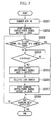
digital camera 2100 at the time of charging is described with reference toFIG. 5 . The flowchart shown inFIG. 5 begins by theUSB cable 2300 being inserted to the USB I/F 2113 (step S2001). Incidentally, the other end of theUSB cable 2300 is assumed to be connected to thehost device 2200. - The CPU 2104 makes the
power circuit 2111 charge the chargingtype battery 2112 by the electric current supplied from the USB cable 2300 (step S2002). In other words, thepower circuit 2111 follows the command of the CPU 2104, and switches the electric source of the electric current supplied to each processing unit to an electric current provided from thehost device 2200 via the USB cable 2300 (step S2002), - Subsequent to step S2002, the CPU 2104 determines whether or not the
lens barrel 2003 has been collapsed into the camera body 2001 (step S2003). In other words, the CPU 2104 determines whether or not thelens barrel 2003 is in a collapsed condition (step S2003). For instance, the CPU 2104 transmits to thebarrel driving unit 2116, a command to determine the condition of thelens barrel 2003. When the CPU 2104 receives a response from thebarrel driving unit 2116 to this command indicating a determination result that thelens barrel 2003 is in a collapsed condition, the CPU 2104 determines that thelens barrel 2003 is already collapsed inside thecamera body 2001. When the CPU 2104 determines that thelens barrel 2003 is already collapsed inside the camera body 2001 (step S2003: YES), the routine proceeds to step S2008, skipping steps S2004 through S2007. - When the CPU 2104 determines that the
lens barrel 2003 is not collapsed into the camera body 2001 (step S2003: NO), the CPU 1204 determines whether or not the chargingtype battery 2112 is charged by an amount greater than or equal to a predetermined amount (step S2004), For instance, when the chargingtype battery 2112 is charged by an amount greater than or equal to a predetermined amount, thepower circuit 2111 sends a notification to the CPU 2104 indicating that the chargingtype battery 2112 is charged by an amount greater than or equal to a predetermined amount. The CPU 2104 determines whether or not the chargingtype battery 2112 has been charged by an amount greater than or equal to a predetermined amount depending on whether the above notification is received. Incidentally, the predetermined amount, which is a criterion for the above determination, is an electric voltage such that the electric current for driving the lens barrel can be supplied in order to transition thelens barrel 2003 from the photographing condition to the collapsed condition. An example of this predetermined amount is 3.4V. When the CPU 2104 determines that the chargingtype battery 2112 has not bee charged by an amount greater than the predetermined amount (step S2004: NO), the CPU 2104 repeats making this determination (step S2004) until it is determined that the chargingtype battery 2112 has been charged by an amount greater than or equal to the predetermined amount. - When the CPU 2104 determines that the charging
type battery 2112 has been charged by an amount greater than a predetermined amount (step S2004: YES), the CPU 2104 makes thepower circuit 2111 supply the current for driving the lens barrel from the chargingtype battery 2112 to the barrel driving unit 2116 (step S2005), In other words, thepower circuit 2111 follows the command from the CPU 2104 and switches the power source of the electric current supplied to each processing unit from an electric current supplied by thehost device 2200 via theUSB cable 2300 to thecharging type battery 2112. At the same time, thepower circuit 2111 supplies the electric current for driving the lens barrel from the chargingtype battery 2112 to the barrel driving unit 2116 (step S2005). In other words, thepower circuit 2111 stops the charging of the chargingtype battery 2112, and begins to supply the electric current for driving the lens barrel from the chargingtype battery 2112 to thebarrel driving unit 2116. - Following step S2005, the CPU 2104 transmits a command to the
barrel driving unit 2116 so that the condition of thelens barrel 2003 is transitioned to the collapsed condition. When thebarrel driving unit 2116 receives this command, thebarrel driving unit 2116 stores thelens barrel 2003 into thecamera body 2001 by the electric current for driving the lens barrel supplied by the chargingtype battery 2112. In other words, thebarrel driving unit 2116 makes the condition of thelens barrel 2003 transition to the collapsed condition (step S2006), - Following step S2006, the CPU 2104 charges the charging
type battery 2112 by the electric current supplied to thepower circuit 2111 from the USB cable 2300 (step S2007). IN other words, thepower circuit 2111 follows the command from the CPU 2104 and switches the power source of the electric current supplied to thedigital camera 2100 from the chargingtype battery 2112 to the electric current supplied by thehost device 2200 via the USB cable 2300 (step S2007). In other words, thepower circuit 2111 stops supplying the electric current for driving the lens barrel from the chargingtype battery 2112 to thebarrel driving unit 2116, and begins charging the chargingtype battery 2112. - Following step S2003 (YES) or step S2007, the CPU 2104 determines whether or not the charging of the charging
type battery 2112 has been completed (step S2008). For example, when the charging of the chargingtype battery 2112 has been completed, thepower circuit 2111 sends a notification to the CPU 2104 that the charging has been completed. The CPU 2104 determines whether or not the charging of the chargingtype battery 2112 has been completed, according to whether or not there is the above mentioned notification. When the CPU 2104 determines that the charging of the chargingtype battery 2112 has not been completed (step S2008: NO), the routine returns to step S2003, and determines once again whether or not thelens barrel 2003 has been stored inside thecamera body 2001. Meanwhile, when the CPU 2104 determines that the charging of the chargingtype battery 2112 has been completed (step S2008: YES), the processing of the flowchart shown inFIG. 5 is completed. - According to the flowchart shown in
FIG. 5 , even if the chargingtype battery 2112 has not been charged at all when theUSB cable 2300 is connected to thedigital camera 2100, thelens barrel 2003 of which is in a photographing condition, the chargingtype battery 2112 is charged gradually. When the capacity is reached such that the electric current necessary for driving thelens barrel 2003 can be supplied, thelens barrel 2003 transitions from the photographing condition to the collapsed condition according to the electric current supplied by the chargingtype battery 2112. - Heretofore, the second embodiment of the present invention has been described in detail in reference to the diagrams. However, the concrete configuration is not limited by the examples described above. Various modifications may be made within the gist of the present invention.
- For example, according to the above embodiment, in step S2008 of the flowchart shown in
FIG. 5 , when the CPU 2104 determines that the charging of the chargingtype battery 2112 has not been completed (step S2008; NO), the CPU 2104 may repeat making this determination (step S2009) without returning to step S2004 until a determination is made that the charging of the chargingtype battery 2112 has been completed. In addition, in step S2003, thebarrel driving unit 2116 followed the command from the CPU 2104 and determined whether or not thelens barrel 2003 is in a collapsed condition. Further, the CPU 2104 determined whether or not thelens barrel 2003 is already stored into thecamera body 2001 based on the determination result obtained from thebarrel driving unit 2116. However, for example, thebarrel driving unit 2116 may temporarily store the information indicating the condition of thelens barrel 2003 after the transition into thebuffer memory 2107, and the CPU 2104 may refer to the information being temporarily stored and determine whether or not thelens barrel 2003 is already stored inside thecamera body 2001. - Further, in the above description, it was explained that an example of a predetermined condition of the
digital camera 2100 when theUSB cable 2300 is connected to the USB I/F 2113 is the collapsed condition. However under this situation, the predetermined condition of thedigital camera 2100 may be a strobe charging completion condition in which the charging of thestrobe 2013 has been completed. Incidentally, in order to reach the strobe charging completion condition, the electric current for charging the strobe, which exceeds a predetermined standard, is necessary as described above. In addition, the CPU 2104, for instance, determines whether or not the strobe charging completion condition is reached, which is a predetermined condition in which the electric current for charging the strobe is necessary. As mentioned above, the electric current for charging the strobe is a necessary amount of electric current exceeding the predetermined standard. - In other words, when the predetermined condition of the
digital camera 2100 when theUSB cable 2300 is connected to the USB I/F 2113, and the strobe charging completion condition, which is a predetermined condition, has not been reached, and it is confirmed by thepower circuit 2111 that the chargingtype battery 2112 cannot supply a predetermined amount of electric current exceeding the amount of electric current for charging the strobe, the CPU 2104 makes thepower circuit 2111 charge the chargingtype battery 2112 until thepower circuit 2111 confirms that an electric current exceeding the predetermined amount can be supplied. Then, the CPU 2104 may make thepower circuit 2111 supply the predetermined amount of electric current from the chargingtype battery 2112 to thestrobe 2013. Incidentally, the amount of electric current supplied from the chargingtype battery 2112 which has almost completed the charging process may be set as the above predetermined amount. By lagging the time that the charging is completed, by starting the charging of thestrobe 2013 at a later time compared to the chargeable timing of thestrobe 2013, it is possible to prevent the influence of the decline of the power of thestrobe 2013 due to the self-discharging which begins after the charging is completed. - In addition, the predetermined condition of the
digital camera 2100 in a situation in which theUSB cable 2300 is connected to the USB I/F 2113 may be a display completion condition, which is a condition in which a predetermined content is displayed according to a demand by themonitor 2009. Further, in order for the display completion condition is reached, an electric current for display exceeding a predetermined standard is necessary, as described above. In addition, the CPU 2104 determines whether or not the display completion condition is reached, The display completion condition is a predetermined condition in which the electric current for displaying is needed. The electric current for displaying is a necessary amount of electric current exceeding a predetermined standard. - In other words, when the predetermined condition of the
digital camera 2100 when theUSB cable 2300 is connected to the USB I/F 2113, and the predetermined condition of thedigital camera 2100 is the display completion condition, the display completion condition is not reached, and it is confirmed by thepower circuit 2111 that the chargingtype battery 2112 cannot supply the electric current for displaying, the CPU 2104 makes thepower circuit 2111 execute the charging process until thepower circuit 2111 confirms that the electric current for displaying can be supplied. Then, the CPU 2104 may make thepower circuit 2111 supply the electric current for displaying from the chargingtype battery 2112 to themonitor 2009. - According to the above second embodiment, while the charging
type battery 2112 is being charged by an electric current of a predetermined standard via theUSB cable 2300, it is possible to appropriately execute an operation such as the driving of thelens barrel 2003 which requires a large amount of electric current exceeding the predetermined standard, as well as operations such as the charging of thestrobe 2013 and the output to themonitor 2009. Therefore, for example, it is possible to avoid the risk accompanying a situation in which thecharging type battery 2112 is charged via theUSB cable 2300 while thelens barrel 2003 is in a photographing condition (for instance, the risk that theimaging lens 2101 may be scratched or, the risk that theimaging lens 2101 may become dusty). In addition, when the chargingtype battery 2112 is being charged via theUSB cable 2300, thestrobe 2013 may be charged as well. Therefore, at least when the charging of the chargingtype battery 2112 has been completed, it is possible to immediately use thestrobe 2013. In addition, when the chargingtype battery 2112 is being charged via theUSB cable 2300, for instance, electric current is supplied to themonitor 2009. As a result, it is possible to conduct an operation such as direct print via themonitor 2009. - Moreover, according to the above description regarding the present embodiment, an instance in which the CPU 2104 controls the electric current was described as an example of an electric power control of the charging of the charging
type battery 2112 and a control of the electric power supplied to each processing unit from the chargingtype battery 2112. However, the CPU 2104 may control the electric voltage. - In addition, an example in which the present embodiment of the present invention was applied to a digital camera was used in the above example. However, the present invention is not limited to this configuration. For instance, a similar effect may be achieved by applying the present invention to other electronic devices such as a portable phone or a music player.
- Further, in the present embodiment, a case using a USB cable as a power feeding cable was described. However, the power feeding cable according to the present invention is not limited to a USB cable, For instance, a connecting wire such as a LAN (Local Area Network) cable, which can supply an electric current of a predetermined standard, may be used. In addition, instead of using a USB cable or a LAN cable which are cables that can transmit and receive information, it is also possible to use a connection wire which can simply supply an electric current of a predetermined standard.
- The
digital camera 2100 includes a computer system in the interior. In addition, the operation of the CPU 2104 is recorded in theflash ROM 2108 in the form of a program. The above process is executed by the computer reading out this program and executing the program. In addition, this computer program may be transmitted to a computer via a transmission network, and the computer that has received this transmission may execute this program. - Furthermore, the above program may be a program for executing a part of the feature described above. Moreover, the above program may be a program that realizes the above feature by being executed in combination with another program which is already recorded in the computer system. This type of program is known as a difference file (difference program).
- While a referred embodiment of the present invention has been described above, it should be understood that these are exemplary of the invention and are not to be considered as limiting the present invention. Addictions, omissions, substitutions, and other modifications can be made without departing from the scope of the present invention. The invention is not to be considered as being limited by the foregoing description, and is only limited by the scope of the appended claims.
Claims (9)
- An electronic device (100) comprising:a connecting unit (114, 115) connected to a connection line supplying an electric power of a predetermined rating and transmitting and receiving an information;a charging unit (111) conducting a changing of a charging battery connected to an own device, by the electric power supplied by the connection line;an electric supplying unit (109) supplying an electric power to a recording medium storing an information;a reading-and-writing unit (108) performing a reading-and-writing operation of the recording medium; andan electronic source controlling unit (104) performing a control of the electric power supplied to the charging unit (111), when the reading-and-writing unit (108) performs the reading-and-writing operation of the recording medium, according to an access request to the recording medium via the connection line.
- The electronic device (100) according to claim 1, wherein the electric source controlling unit reduces an amount of electric power supplied for performing the reading-and-writing operation from an amount of electric power supplied to the charging battery.
- The electronic device (100) according to claim 1, wherein the power source controlling unit returns the amount of electric power supplied to the charging unit (111) to a previous amount of electric power before the control is performed, when the access request does not exist within a predetermined amount of time after the reading-and-writing operation by the reading-and-writing unit (108) is complected.
- The electronic device (100) according to claim 1, wherein the electric source controlling unit alters the amount of electric power supplied to the charging unit (111) according to a type of the recording medium.
- The electronic device (100) according to claim 1 further comprising:a condition determination unit determining whether or not the own device is in a predetermine condition requiring a predetermined necessary electric power exceeding the predetermined rating;a charging amount confirmation unit confirming a charging amount of the changing battery;an electric power supplying unit supplying an electric power from the charging battery, whereinwhile the connection line is being connected, the condition determination unit determines that the predetermined condition is not reached, and the charging amount confirmation unit confirms that the predetermined necessary electric power cannot be supplied by the charging battery, the electric source controlling unit makes the electric power supplying unit supply the predetermined necessary electric power from the charging battery after the electric source controlling unit makes the changing unit (111) conduct the charging.
- The electronic device (100) according to claim 5, wherein
the predetermined condition while the connection line is connected is collapsed condition, which is a condition of a lens barrel transitioning by a lens barrel driving unit wherein a length in an optical axis direction is shorter compared to a length in the optical axis direction in a photographing condition during which a photographing is conducted;
the predetermined necessary electric power for reaching the predetermined condition is an electric power for driving the lens barrel so that the photographing condition is transitioned to the collapsed condition due to the lens barrel driving unit; and
while the connection line is being connected, the condition determination unit determines that the collapsed condition is not reached, and the charging amount confirmation unit confirms that the electric power for driving the lens barrel cannot be supplied by the charging battery, the electric source controlling unit makes the electric power supplying unit supply the electric power for driving the lens barrel to the lens barrel driving unit after the electric source controlling unit makes the charging unit (111) conduct the charging until the charging amount confirmation unit confirms that the electric power for driving the lens barrel can be supplied. - The electronic device (100) according to claim 5 wherein, while the connection line is connected, the electric source controlling unit makes the electric power supplying unit supply the predetermined necessary electric power, and the condition determination unit determines that the predetermined condition has been reached, the electric source controlling unit again makes the charging unit (111) perform the charging.
- A method of controlling an electronic power supply of an electronic device (100) comprising a charging unit (111), a reading-and-writing unit (108), an electric source controlling unit, and an electric power supplying unit, the method comprising:charging, by the charging unit (111), of a charging battery connected to an own device, by an electric power supplied by a connection line supplying an electric power of a predetermined rating and transmitting and receiving an information;performing, by the reading-and-writing unit (108), of a reading-and-writing operation of a recording medium recording an information;performing, by the electronic source controlling unit (104), of a a control of the electric power supplied to the charging unit (111), when the reading-and-writing unit (108) performs the reading-and-writing operation of the recording medium recording the information;supplying, by the power supplying unit, of an electric power to the recording medium; andperforming, by the reading-and-writing unit (108), of a reading-end-writing operation of the recording medium.
- The method of controlling the electronic power supply according to claim 8, wherein
the electronic device (100) further comprises a condition determination unit and a charging amount confirmation unit; and wherein
the method further comprises:determining, by the condition determination unit whether or not the own device is in a predetermined condition requiring a predetermined necessary electric power exceeding the predetermined rating;confirming, by the charging amount confirmation unit, of a charging amount of the charging battery; andsupplying, by the electronic power supplying unit, of an electronic power from the charging battery, whereinwhile the connection line is being connected, it is determined that the predetermined condition is not reached, and it is confirmed that the predetermined necessary electric power cannot be supplied by the charging battery, the electric source controlling unit makes the electric power supplying unit supply the predetermined necessary electric power from the charging battery after the electric source controlling unit makes the charging unit (111) conduct the charging,
Applications Claiming Priority (2)
| Application Number | Priority Date | Filing Date | Title |
|---|---|---|---|
| JP2009158764A JP5056805B2 (en) | 2009-07-03 | 2009-07-03 | Electronic device, supply power control method and program |
| JP2009163596A JP4816772B2 (en) | 2009-07-10 | 2009-07-10 | Electronic device, current supply method and program |
Publications (2)
| Publication Number | Publication Date |
|---|---|
| EP2275902A2 true EP2275902A2 (en) | 2011-01-19 |
| EP2275902A3 EP2275902A3 (en) | 2014-07-09 |
Family
ID=42634636
Family Applications (1)
| Application Number | Title | Priority Date | Filing Date |
|---|---|---|---|
| EP10168084.1A Withdrawn EP2275902A3 (en) | 2009-07-03 | 2010-07-01 | Electronic device and method controlling electronic power supply |
Country Status (3)
| Country | Link |
|---|---|
| US (3) | US9030166B2 (en) |
| EP (1) | EP2275902A3 (en) |
| CN (1) | CN101944753A (en) |
Families Citing this family (366)
| Publication number | Priority date | Publication date | Assignee | Title |
|---|---|---|---|---|
| US9060770B2 (en) | 2003-05-20 | 2015-06-23 | Ethicon Endo-Surgery, Inc. | Robotically-driven surgical instrument with E-beam driver |
| US20070084897A1 (en) | 2003-05-20 | 2007-04-19 | Shelton Frederick E Iv | Articulating surgical stapling instrument incorporating a two-piece e-beam firing mechanism |
| US9072535B2 (en) | 2011-05-27 | 2015-07-07 | Ethicon Endo-Surgery, Inc. | Surgical stapling instruments with rotatable staple deployment arrangements |
| US11890012B2 (en) | 2004-07-28 | 2024-02-06 | Cilag Gmbh International | Staple cartridge comprising cartridge body and attached support |
| US8215531B2 (en) | 2004-07-28 | 2012-07-10 | Ethicon Endo-Surgery, Inc. | Surgical stapling instrument having a medical substance dispenser |
| US11998198B2 (en) | 2004-07-28 | 2024-06-04 | Cilag Gmbh International | Surgical stapling instrument incorporating a two-piece E-beam firing mechanism |
| US7934630B2 (en) | 2005-08-31 | 2011-05-03 | Ethicon Endo-Surgery, Inc. | Staple cartridges for forming staples having differing formed staple heights |
| US11484312B2 (en) | 2005-08-31 | 2022-11-01 | Cilag Gmbh International | Staple cartridge comprising a staple driver arrangement |
| US9237891B2 (en) | 2005-08-31 | 2016-01-19 | Ethicon Endo-Surgery, Inc. | Robotically-controlled surgical stapling devices that produce formed staples having different lengths |
| US7669746B2 (en) | 2005-08-31 | 2010-03-02 | Ethicon Endo-Surgery, Inc. | Staple cartridges for forming staples having differing formed staple heights |
| US11246590B2 (en) | 2005-08-31 | 2022-02-15 | Cilag Gmbh International | Staple cartridge including staple drivers having different unfired heights |
| US10159482B2 (en) | 2005-08-31 | 2018-12-25 | Ethicon Llc | Fastener cartridge assembly comprising a fixed anvil and different staple heights |
| US20070106317A1 (en) | 2005-11-09 | 2007-05-10 | Shelton Frederick E Iv | Hydraulically and electrically actuated articulation joints for surgical instruments |
| US8186555B2 (en) | 2006-01-31 | 2012-05-29 | Ethicon Endo-Surgery, Inc. | Motor-driven surgical cutting and fastening instrument with mechanical closure system |
| US11278279B2 (en) | 2006-01-31 | 2022-03-22 | Cilag Gmbh International | Surgical instrument assembly |
| US20110290856A1 (en) | 2006-01-31 | 2011-12-01 | Ethicon Endo-Surgery, Inc. | Robotically-controlled surgical instrument with force-feedback capabilities |
| US7845537B2 (en) | 2006-01-31 | 2010-12-07 | Ethicon Endo-Surgery, Inc. | Surgical instrument having recording capabilities |
| US7753904B2 (en) | 2006-01-31 | 2010-07-13 | Ethicon Endo-Surgery, Inc. | Endoscopic surgical instrument with a handle that can articulate with respect to the shaft |
| US20110024477A1 (en) | 2009-02-06 | 2011-02-03 | Hall Steven G | Driven Surgical Stapler Improvements |
| US11793518B2 (en) | 2006-01-31 | 2023-10-24 | Cilag Gmbh International | Powered surgical instruments with firing system lockout arrangements |
| US11224427B2 (en) | 2006-01-31 | 2022-01-18 | Cilag Gmbh International | Surgical stapling system including a console and retraction assembly |
| US8820603B2 (en) | 2006-01-31 | 2014-09-02 | Ethicon Endo-Surgery, Inc. | Accessing data stored in a memory of a surgical instrument |
| US20120292367A1 (en) | 2006-01-31 | 2012-11-22 | Ethicon Endo-Surgery, Inc. | Robotically-controlled end effector |
| US8708213B2 (en) | 2006-01-31 | 2014-04-29 | Ethicon Endo-Surgery, Inc. | Surgical instrument having a feedback system |
| US8992422B2 (en) | 2006-03-23 | 2015-03-31 | Ethicon Endo-Surgery, Inc. | Robotically-controlled endoscopic accessory channel |
| US8322455B2 (en) | 2006-06-27 | 2012-12-04 | Ethicon Endo-Surgery, Inc. | Manually driven surgical cutting and fastening instrument |
| US10568652B2 (en) | 2006-09-29 | 2020-02-25 | Ethicon Llc | Surgical staples having attached drivers of different heights and stapling instruments for deploying the same |
| US11980366B2 (en) | 2006-10-03 | 2024-05-14 | Cilag Gmbh International | Surgical instrument |
| US11291441B2 (en) | 2007-01-10 | 2022-04-05 | Cilag Gmbh International | Surgical instrument with wireless communication between control unit and remote sensor |
| US8684253B2 (en) | 2007-01-10 | 2014-04-01 | Ethicon Endo-Surgery, Inc. | Surgical instrument with wireless communication between a control unit of a robotic system and remote sensor |
| US8632535B2 (en) | 2007-01-10 | 2014-01-21 | Ethicon Endo-Surgery, Inc. | Interlock and surgical instrument including same |
| US20080169332A1 (en) | 2007-01-11 | 2008-07-17 | Shelton Frederick E | Surgical stapling device with a curved cutting member |
| US11039836B2 (en) | 2007-01-11 | 2021-06-22 | Cilag Gmbh International | Staple cartridge for use with a surgical stapling instrument |
| US8727197B2 (en) | 2007-03-15 | 2014-05-20 | Ethicon Endo-Surgery, Inc. | Staple cartridge cavity configuration with cooperative surgical staple |
| US8931682B2 (en) | 2007-06-04 | 2015-01-13 | Ethicon Endo-Surgery, Inc. | Robotically-controlled shaft based rotary drive systems for surgical instruments |
| US11857181B2 (en) | 2007-06-04 | 2024-01-02 | Cilag Gmbh International | Robotically-controlled shaft based rotary drive systems for surgical instruments |
| US7753245B2 (en) | 2007-06-22 | 2010-07-13 | Ethicon Endo-Surgery, Inc. | Surgical stapling instruments |
| US11849941B2 (en) | 2007-06-29 | 2023-12-26 | Cilag Gmbh International | Staple cartridge having staple cavities extending at a transverse angle relative to a longitudinal cartridge axis |
| US8573465B2 (en) | 2008-02-14 | 2013-11-05 | Ethicon Endo-Surgery, Inc. | Robotically-controlled surgical end effector system with rotary actuated closure systems |
| RU2493788C2 (en) | 2008-02-14 | 2013-09-27 | Этикон Эндо-Серджери, Инк. | Surgical cutting and fixing instrument, which has radio-frequency electrodes |
| US8636736B2 (en) | 2008-02-14 | 2014-01-28 | Ethicon Endo-Surgery, Inc. | Motorized surgical cutting and fastening instrument |
| US9179912B2 (en) | 2008-02-14 | 2015-11-10 | Ethicon Endo-Surgery, Inc. | Robotically-controlled motorized surgical cutting and fastening instrument |
| US7866527B2 (en) | 2008-02-14 | 2011-01-11 | Ethicon Endo-Surgery, Inc. | Surgical stapling apparatus with interlockable firing system |
| US11986183B2 (en) | 2008-02-14 | 2024-05-21 | Cilag Gmbh International | Surgical cutting and fastening instrument comprising a plurality of sensors to measure an electrical parameter |
| US7819298B2 (en) | 2008-02-14 | 2010-10-26 | Ethicon Endo-Surgery, Inc. | Surgical stapling apparatus with control features operable with one hand |
| US20130153641A1 (en) | 2008-02-15 | 2013-06-20 | Ethicon Endo-Surgery, Inc. | Releasable layer of material and surgical end effector having the same |
| US11648005B2 (en) | 2008-09-23 | 2023-05-16 | Cilag Gmbh International | Robotically-controlled motorized surgical instrument with an end effector |
| US9005230B2 (en) | 2008-09-23 | 2015-04-14 | Ethicon Endo-Surgery, Inc. | Motorized surgical instrument |
| US9386983B2 (en) | 2008-09-23 | 2016-07-12 | Ethicon Endo-Surgery, Llc | Robotically-controlled motorized surgical instrument |
| US8210411B2 (en) | 2008-09-23 | 2012-07-03 | Ethicon Endo-Surgery, Inc. | Motor-driven surgical cutting instrument |
| US8608045B2 (en) | 2008-10-10 | 2013-12-17 | Ethicon Endo-Sugery, Inc. | Powered surgical cutting and stapling apparatus with manually retractable firing system |
| US8517239B2 (en) | 2009-02-05 | 2013-08-27 | Ethicon Endo-Surgery, Inc. | Surgical stapling instrument comprising a magnetic element driver |
| JP2012517287A (en) | 2009-02-06 | 2012-08-02 | エシコン・エンド−サージェリィ・インコーポレイテッド | Improvement of driven surgical stapler |
| CN101944753A (en) * | 2009-07-03 | 2011-01-12 | 株式会社尼康 | Electronic equipment, supply capability control method and electric current supply method |
| US8851354B2 (en) | 2009-12-24 | 2014-10-07 | Ethicon Endo-Surgery, Inc. | Surgical cutting instrument that analyzes tissue thickness |
| US8220688B2 (en) | 2009-12-24 | 2012-07-17 | Ethicon Endo-Surgery, Inc. | Motor-driven surgical cutting instrument with electric actuator directional control assembly |
| US8783543B2 (en) | 2010-07-30 | 2014-07-22 | Ethicon Endo-Surgery, Inc. | Tissue acquisition arrangements and methods for surgical stapling devices |
| US9629814B2 (en) | 2010-09-30 | 2017-04-25 | Ethicon Endo-Surgery, Llc | Tissue thickness compensator configured to redistribute compressive forces |
| US12213666B2 (en) | 2010-09-30 | 2025-02-04 | Cilag Gmbh International | Tissue thickness compensator comprising layers |
| US11925354B2 (en) | 2010-09-30 | 2024-03-12 | Cilag Gmbh International | Staple cartridge comprising staples positioned within a compressible portion thereof |
| US10405854B2 (en) | 2010-09-30 | 2019-09-10 | Ethicon Llc | Surgical stapling cartridge with layer retention features |
| US9320523B2 (en) | 2012-03-28 | 2016-04-26 | Ethicon Endo-Surgery, Llc | Tissue thickness compensator comprising tissue ingrowth features |
| US11812965B2 (en) | 2010-09-30 | 2023-11-14 | Cilag Gmbh International | Layer of material for a surgical end effector |
| US11298125B2 (en) | 2010-09-30 | 2022-04-12 | Cilag Gmbh International | Tissue stapler having a thickness compensator |
| US10945731B2 (en) | 2010-09-30 | 2021-03-16 | Ethicon Llc | Tissue thickness compensator comprising controlled release and expansion |
| US9241714B2 (en) | 2011-04-29 | 2016-01-26 | Ethicon Endo-Surgery, Inc. | Tissue thickness compensator and method for making the same |
| US9113865B2 (en) | 2010-09-30 | 2015-08-25 | Ethicon Endo-Surgery, Inc. | Staple cartridge comprising a layer |
| US8695866B2 (en) | 2010-10-01 | 2014-04-15 | Ethicon Endo-Surgery, Inc. | Surgical instrument having a power control circuit |
| BR112013027794B1 (en) | 2011-04-29 | 2020-12-15 | Ethicon Endo-Surgery, Inc | CLAMP CARTRIDGE SET |
| US11207064B2 (en) | 2011-05-27 | 2021-12-28 | Cilag Gmbh International | Automated end effector component reloading system for use with a robotic system |
| CN103186217A (en) * | 2011-12-30 | 2013-07-03 | 深圳富泰宏精密工业有限公司 | Portable electronic device and voltage transforming circuit thereof |
| MX358135B (en) | 2012-03-28 | 2018-08-06 | Ethicon Endo Surgery Inc | Tissue thickness compensator comprising a plurality of layers. |
| MX350846B (en) | 2012-03-28 | 2017-09-22 | Ethicon Endo Surgery Inc | Tissue thickness compensator comprising capsules defining a low pressure environment. |
| CN104379068B (en) | 2012-03-28 | 2017-09-22 | 伊西康内外科公司 | Holding device assembly including tissue thickness compensation part |
| US9101358B2 (en) | 2012-06-15 | 2015-08-11 | Ethicon Endo-Surgery, Inc. | Articulatable surgical instrument comprising a firing drive |
| US9282974B2 (en) | 2012-06-28 | 2016-03-15 | Ethicon Endo-Surgery, Llc | Empty clip cartridge lockout |
| US9226751B2 (en) | 2012-06-28 | 2016-01-05 | Ethicon Endo-Surgery, Inc. | Surgical instrument system including replaceable end effectors |
| JP6290201B2 (en) | 2012-06-28 | 2018-03-07 | エシコン・エンド−サージェリィ・インコーポレイテッドEthicon Endo−Surgery,Inc. | Lockout for empty clip cartridge |
| BR112014032776B1 (en) | 2012-06-28 | 2021-09-08 | Ethicon Endo-Surgery, Inc | SURGICAL INSTRUMENT SYSTEM AND SURGICAL KIT FOR USE WITH A SURGICAL INSTRUMENT SYSTEM |
| US12383267B2 (en) | 2012-06-28 | 2025-08-12 | Cilag Gmbh International | Robotically powered surgical device with manually-actuatable reversing system |
| US20140001231A1 (en) | 2012-06-28 | 2014-01-02 | Ethicon Endo-Surgery, Inc. | Firing system lockout arrangements for surgical instruments |
| US9289256B2 (en) | 2012-06-28 | 2016-03-22 | Ethicon Endo-Surgery, Llc | Surgical end effectors having angled tissue-contacting surfaces |
| US11197671B2 (en) | 2012-06-28 | 2021-12-14 | Cilag Gmbh International | Stapling assembly comprising a lockout |
| JP6288913B2 (en) * | 2012-12-28 | 2018-03-07 | キヤノン株式会社 | Electronic device and program |
| MX368026B (en) | 2013-03-01 | 2019-09-12 | Ethicon Endo Surgery Inc | Articulatable surgical instruments with conductive pathways for signal communication. |
| RU2669463C2 (en) | 2013-03-01 | 2018-10-11 | Этикон Эндо-Серджери, Инк. | Surgical instrument with soft stop |
| US9351726B2 (en) | 2013-03-14 | 2016-05-31 | Ethicon Endo-Surgery, Llc | Articulation control system for articulatable surgical instruments |
| US9629629B2 (en) | 2013-03-14 | 2017-04-25 | Ethicon Endo-Surgey, LLC | Control systems for surgical instruments |
| US9801626B2 (en) | 2013-04-16 | 2017-10-31 | Ethicon Llc | Modular motor driven surgical instruments with alignment features for aligning rotary drive shafts with surgical end effector shafts |
| BR112015026109B1 (en) | 2013-04-16 | 2022-02-22 | Ethicon Endo-Surgery, Inc | surgical instrument |
| US20150053737A1 (en) | 2013-08-23 | 2015-02-26 | Ethicon Endo-Surgery, Inc. | End effector detection systems for surgical instruments |
| MX369362B (en) | 2013-08-23 | 2019-11-06 | Ethicon Endo Surgery Llc | Firing member retraction devices for powered surgical instruments. |
| US9962161B2 (en) | 2014-02-12 | 2018-05-08 | Ethicon Llc | Deliverable surgical instrument |
| US12232723B2 (en) | 2014-03-26 | 2025-02-25 | Cilag Gmbh International | Systems and methods for controlling a segmented circuit |
| BR112016021943B1 (en) | 2014-03-26 | 2022-06-14 | Ethicon Endo-Surgery, Llc | SURGICAL INSTRUMENT FOR USE BY AN OPERATOR IN A SURGICAL PROCEDURE |
| US20150272557A1 (en) | 2014-03-26 | 2015-10-01 | Ethicon Endo-Surgery, Inc. | Modular surgical instrument system |
| US9750499B2 (en) | 2014-03-26 | 2017-09-05 | Ethicon Llc | Surgical stapling instrument system |
| US10013049B2 (en) | 2014-03-26 | 2018-07-03 | Ethicon Llc | Power management through sleep options of segmented circuit and wake up control |
| US10327764B2 (en) | 2014-09-26 | 2019-06-25 | Ethicon Llc | Method for creating a flexible staple line |
| JP6532889B2 (en) | 2014-04-16 | 2019-06-19 | エシコン エルエルシーEthicon LLC | Fastener cartridge assembly and staple holder cover arrangement |
| US10561422B2 (en) | 2014-04-16 | 2020-02-18 | Ethicon Llc | Fastener cartridge comprising deployable tissue engaging members |
| CN106456176B (en) | 2014-04-16 | 2019-06-28 | 伊西康内外科有限责任公司 | Fastener Cartridge Including Extensions With Different Configurations |
| US20150297223A1 (en) | 2014-04-16 | 2015-10-22 | Ethicon Endo-Surgery, Inc. | Fastener cartridges including extensions having different configurations |
| CN106456158B (en) | 2014-04-16 | 2019-02-05 | 伊西康内外科有限责任公司 | Fastener magazines including non-conforming fasteners |
| JP6530658B2 (en) | 2014-08-11 | 2019-06-12 | キヤノン株式会社 | Imaging device, control method therefor, program, and recording medium |
| US9724094B2 (en) | 2014-09-05 | 2017-08-08 | Ethicon Llc | Adjunct with integrated sensors to quantify tissue compression |
| BR112017004361B1 (en) | 2014-09-05 | 2023-04-11 | Ethicon Llc | ELECTRONIC SYSTEM FOR A SURGICAL INSTRUMENT |
| US11311294B2 (en) | 2014-09-05 | 2022-04-26 | Cilag Gmbh International | Powered medical device including measurement of closure state of jaws |
| US10105142B2 (en) | 2014-09-18 | 2018-10-23 | Ethicon Llc | Surgical stapler with plurality of cutting elements |
| US11523821B2 (en) | 2014-09-26 | 2022-12-13 | Cilag Gmbh International | Method for creating a flexible staple line |
| JP6648119B2 (en) | 2014-09-26 | 2020-02-14 | エシコン エルエルシーEthicon LLC | Surgical stapling buttress and accessory materials |
| US9924944B2 (en) | 2014-10-16 | 2018-03-27 | Ethicon Llc | Staple cartridge comprising an adjunct material |
| US11141153B2 (en) | 2014-10-29 | 2021-10-12 | Cilag Gmbh International | Staple cartridges comprising driver arrangements |
| US10517594B2 (en) | 2014-10-29 | 2019-12-31 | Ethicon Llc | Cartridge assemblies for surgical staplers |
| US9844376B2 (en) | 2014-11-06 | 2017-12-19 | Ethicon Llc | Staple cartridge comprising a releasable adjunct material |
| US10736636B2 (en) | 2014-12-10 | 2020-08-11 | Ethicon Llc | Articulatable surgical instrument system |
| US9844374B2 (en) | 2014-12-18 | 2017-12-19 | Ethicon Llc | Surgical instrument systems comprising an articulatable end effector and means for adjusting the firing stroke of a firing member |
| US9844375B2 (en) | 2014-12-18 | 2017-12-19 | Ethicon Llc | Drive arrangements for articulatable surgical instruments |
| RU2703684C2 (en) | 2014-12-18 | 2019-10-21 | ЭТИКОН ЭНДО-СЕРДЖЕРИ, ЭлЭлСи | Surgical instrument with anvil which is selectively movable relative to staple cartridge around discrete fixed axis |
| US10245027B2 (en) | 2014-12-18 | 2019-04-02 | Ethicon Llc | Surgical instrument with an anvil that is selectively movable about a discrete non-movable axis relative to a staple cartridge |
| US10085748B2 (en) | 2014-12-18 | 2018-10-02 | Ethicon Llc | Locking arrangements for detachable shaft assemblies with articulatable surgical end effectors |
| US9987000B2 (en) | 2014-12-18 | 2018-06-05 | Ethicon Llc | Surgical instrument assembly comprising a flexible articulation system |
| TW201626229A (en) * | 2015-01-05 | 2016-07-16 | 致伸科技股份有限公司 | Electrical device with detachable battery |
| US11154301B2 (en) | 2015-02-27 | 2021-10-26 | Cilag Gmbh International | Modular stapling assembly |
| US10548504B2 (en) | 2015-03-06 | 2020-02-04 | Ethicon Llc | Overlaid multi sensor radio frequency (RF) electrode system to measure tissue compression |
| JP2020121162A (en) | 2015-03-06 | 2020-08-13 | エシコン エルエルシーEthicon LLC | Time dependent evaluation of sensor data to determine stability element, creep element and viscoelastic element of measurement |
| US9993248B2 (en) | 2015-03-06 | 2018-06-12 | Ethicon Endo-Surgery, Llc | Smart sensors with local signal processing |
| US10441279B2 (en) | 2015-03-06 | 2019-10-15 | Ethicon Llc | Multiple level thresholds to modify operation of powered surgical instruments |
| US9808246B2 (en) | 2015-03-06 | 2017-11-07 | Ethicon Endo-Surgery, Llc | Method of operating a powered surgical instrument |
| US10245033B2 (en) | 2015-03-06 | 2019-04-02 | Ethicon Llc | Surgical instrument comprising a lockable battery housing |
| US10390825B2 (en) | 2015-03-31 | 2019-08-27 | Ethicon Llc | Surgical instrument with progressive rotary drive systems |
| US11058425B2 (en) | 2015-08-17 | 2021-07-13 | Ethicon Llc | Implantable layers for a surgical instrument |
| JP6653752B2 (en) * | 2015-09-19 | 2020-02-26 | ダイムラー・アクチェンゲゼルシャフトDaimler AG | Shutdown and storage of fuel cell systems at sub-zero temperatures |
| US10105139B2 (en) | 2015-09-23 | 2018-10-23 | Ethicon Llc | Surgical stapler having downstream current-based motor control |
| US10238386B2 (en) | 2015-09-23 | 2019-03-26 | Ethicon Llc | Surgical stapler having motor control based on an electrical parameter related to a motor current |
| US10299878B2 (en) | 2015-09-25 | 2019-05-28 | Ethicon Llc | Implantable adjunct systems for determining adjunct skew |
| US10736633B2 (en) | 2015-09-30 | 2020-08-11 | Ethicon Llc | Compressible adjunct with looping members |
| US11890015B2 (en) | 2015-09-30 | 2024-02-06 | Cilag Gmbh International | Compressible adjunct with crossing spacer fibers |
| US10980539B2 (en) | 2015-09-30 | 2021-04-20 | Ethicon Llc | Implantable adjunct comprising bonded layers |
| US10172620B2 (en) | 2015-09-30 | 2019-01-08 | Ethicon Llc | Compressible adjuncts with bonding nodes |
| US10292704B2 (en) | 2015-12-30 | 2019-05-21 | Ethicon Llc | Mechanisms for compensating for battery pack failure in powered surgical instruments |
| US10368865B2 (en) | 2015-12-30 | 2019-08-06 | Ethicon Llc | Mechanisms for compensating for drivetrain failure in powered surgical instruments |
| US10265068B2 (en) | 2015-12-30 | 2019-04-23 | Ethicon Llc | Surgical instruments with separable motors and motor control circuits |
| US11213293B2 (en) | 2016-02-09 | 2022-01-04 | Cilag Gmbh International | Articulatable surgical instruments with single articulation link arrangements |
| BR112018016098B1 (en) | 2016-02-09 | 2023-02-23 | Ethicon Llc | SURGICAL INSTRUMENT |
| US11224426B2 (en) | 2016-02-12 | 2022-01-18 | Cilag Gmbh International | Mechanisms for compensating for drivetrain failure in powered surgical instruments |
| US10448948B2 (en) | 2016-02-12 | 2019-10-22 | Ethicon Llc | Mechanisms for compensating for drivetrain failure in powered surgical instruments |
| US11179150B2 (en) | 2016-04-15 | 2021-11-23 | Cilag Gmbh International | Systems and methods for controlling a surgical stapling and cutting instrument |
| US10426467B2 (en) | 2016-04-15 | 2019-10-01 | Ethicon Llc | Surgical instrument with detection sensors |
| US10492783B2 (en) | 2016-04-15 | 2019-12-03 | Ethicon, Llc | Surgical instrument with improved stop/start control during a firing motion |
| US10335145B2 (en) | 2016-04-15 | 2019-07-02 | Ethicon Llc | Modular surgical instrument with configurable operating mode |
| US10357247B2 (en) | 2016-04-15 | 2019-07-23 | Ethicon Llc | Surgical instrument with multiple program responses during a firing motion |
| US10828028B2 (en) | 2016-04-15 | 2020-11-10 | Ethicon Llc | Surgical instrument with multiple program responses during a firing motion |
| US11607239B2 (en) | 2016-04-15 | 2023-03-21 | Cilag Gmbh International | Systems and methods for controlling a surgical stapling and cutting instrument |
| US10456137B2 (en) | 2016-04-15 | 2019-10-29 | Ethicon Llc | Staple formation detection mechanisms |
| US11317917B2 (en) | 2016-04-18 | 2022-05-03 | Cilag Gmbh International | Surgical stapling system comprising a lockable firing assembly |
| US20170296173A1 (en) | 2016-04-18 | 2017-10-19 | Ethicon Endo-Surgery, Llc | Method for operating a surgical instrument |
| US10433840B2 (en) | 2016-04-18 | 2019-10-08 | Ethicon Llc | Surgical instrument comprising a replaceable cartridge jaw |
| US10500000B2 (en) | 2016-08-16 | 2019-12-10 | Ethicon Llc | Surgical tool with manual control of end effector jaws |
| US10499914B2 (en) | 2016-12-21 | 2019-12-10 | Ethicon Llc | Staple forming pocket arrangements |
| CN110099619B (en) | 2016-12-21 | 2022-07-15 | 爱惜康有限责任公司 | Latching device for surgical end effector and replaceable tool assembly |
| US20180168615A1 (en) | 2016-12-21 | 2018-06-21 | Ethicon Endo-Surgery, Llc | Method of deforming staples from two different types of staple cartridges with the same surgical stapling instrument |
| US11419606B2 (en) | 2016-12-21 | 2022-08-23 | Cilag Gmbh International | Shaft assembly comprising a clutch configured to adapt the output of a rotary firing member to two different systems |
| US10758230B2 (en) | 2016-12-21 | 2020-09-01 | Ethicon Llc | Surgical instrument with primary and safety processors |
| JP2020501815A (en) | 2016-12-21 | 2020-01-23 | エシコン エルエルシーEthicon LLC | Surgical stapling system |
| JP7010956B2 (en) | 2016-12-21 | 2022-01-26 | エシコン エルエルシー | How to staple tissue |
| US11090048B2 (en) | 2016-12-21 | 2021-08-17 | Cilag Gmbh International | Method for resetting a fuse of a surgical instrument shaft |
| US20180168623A1 (en) | 2016-12-21 | 2018-06-21 | Ethicon Endo-Surgery, Llc | Surgical stapling systems |
| JP7010957B2 (en) | 2016-12-21 | 2022-01-26 | エシコン エルエルシー | Shaft assembly with lockout |
| US10568626B2 (en) | 2016-12-21 | 2020-02-25 | Ethicon Llc | Surgical instruments with jaw opening features for increasing a jaw opening distance |
| MX2019007311A (en) | 2016-12-21 | 2019-11-18 | Ethicon Llc | Surgical stapling systems. |
| US10918385B2 (en) | 2016-12-21 | 2021-02-16 | Ethicon Llc | Surgical system comprising a firing member rotatable into an articulation state to articulate an end effector of the surgical system |
| US10639035B2 (en) | 2016-12-21 | 2020-05-05 | Ethicon Llc | Surgical stapling instruments and replaceable tool assemblies thereof |
| CN110114014B (en) | 2016-12-21 | 2022-08-09 | 爱惜康有限责任公司 | Surgical instrument system including end effector and firing assembly lockout |
| US11134942B2 (en) | 2016-12-21 | 2021-10-05 | Cilag Gmbh International | Surgical stapling instruments and staple-forming anvils |
| US10779823B2 (en) | 2016-12-21 | 2020-09-22 | Ethicon Llc | Firing member pin angle |
| US10667811B2 (en) | 2016-12-21 | 2020-06-02 | Ethicon Llc | Surgical stapling instruments and staple-forming anvils |
| US10617414B2 (en) | 2016-12-21 | 2020-04-14 | Ethicon Llc | Closure member arrangements for surgical instruments |
| US11653914B2 (en) | 2017-06-20 | 2023-05-23 | Cilag Gmbh International | Systems and methods for controlling motor velocity of a surgical stapling and cutting instrument according to articulation angle of end effector |
| US11090046B2 (en) | 2017-06-20 | 2021-08-17 | Cilag Gmbh International | Systems and methods for controlling displacement member motion of a surgical stapling and cutting instrument |
| US10307170B2 (en) | 2017-06-20 | 2019-06-04 | Ethicon Llc | Method for closed loop control of motor velocity of a surgical stapling and cutting instrument |
| US10779820B2 (en) | 2017-06-20 | 2020-09-22 | Ethicon Llc | Systems and methods for controlling motor speed according to user input for a surgical instrument |
| US12490980B2 (en) | 2017-06-20 | 2025-12-09 | Cilag Gmbh International | Surgical instrument having controllable articulation velocity |
| US11382638B2 (en) | 2017-06-20 | 2022-07-12 | Cilag Gmbh International | Closed loop feedback control of motor velocity of a surgical stapling and cutting instrument based on measured time over a specified displacement distance |
| US10980537B2 (en) | 2017-06-20 | 2021-04-20 | Ethicon Llc | Closed loop feedback control of motor velocity of a surgical stapling and cutting instrument based on measured time over a specified number of shaft rotations |
| US11071554B2 (en) | 2017-06-20 | 2021-07-27 | Cilag Gmbh International | Closed loop feedback control of motor velocity of a surgical stapling and cutting instrument based on magnitude of velocity error measurements |
| US11517325B2 (en) | 2017-06-20 | 2022-12-06 | Cilag Gmbh International | Closed loop feedback control of motor velocity of a surgical stapling and cutting instrument based on measured displacement distance traveled over a specified time interval |
| US10881399B2 (en) | 2017-06-20 | 2021-01-05 | Ethicon Llc | Techniques for adaptive control of motor velocity of a surgical stapling and cutting instrument |
| US10993716B2 (en) | 2017-06-27 | 2021-05-04 | Ethicon Llc | Surgical anvil arrangements |
| US11324503B2 (en) | 2017-06-27 | 2022-05-10 | Cilag Gmbh International | Surgical firing member arrangements |
| US11090049B2 (en) | 2017-06-27 | 2021-08-17 | Cilag Gmbh International | Staple forming pocket arrangements |
| US11266405B2 (en) | 2017-06-27 | 2022-03-08 | Cilag Gmbh International | Surgical anvil manufacturing methods |
| US10765427B2 (en) | 2017-06-28 | 2020-09-08 | Ethicon Llc | Method for articulating a surgical instrument |
| US11000279B2 (en) | 2017-06-28 | 2021-05-11 | Ethicon Llc | Surgical instrument comprising an articulation system ratio |
| US11246592B2 (en) | 2017-06-28 | 2022-02-15 | Cilag Gmbh International | Surgical instrument comprising an articulation system lockable to a frame |
| BR112019027065B1 (en) | 2017-06-28 | 2023-12-26 | Ethicon Llc | SURGICAL INSTRUMENT AND SURGICAL SYSTEM |
| US10903685B2 (en) | 2017-06-28 | 2021-01-26 | Ethicon Llc | Surgical shaft assemblies with slip ring assemblies forming capacitive channels |
| US20190000461A1 (en) | 2017-06-28 | 2019-01-03 | Ethicon Llc | Surgical cutting and fastening devices with pivotable anvil with a tissue locating arrangement in close proximity to an anvil pivot axis |
| USD906355S1 (en) | 2017-06-28 | 2020-12-29 | Ethicon Llc | Display screen or portion thereof with a graphical user interface for a surgical instrument |
| US11259805B2 (en) | 2017-06-28 | 2022-03-01 | Cilag Gmbh International | Surgical instrument comprising firing member supports |
| US11564686B2 (en) | 2017-06-28 | 2023-01-31 | Cilag Gmbh International | Surgical shaft assemblies with flexible interfaces |
| EP4070740B1 (en) | 2017-06-28 | 2025-03-26 | Cilag GmbH International | Surgical instrument comprising selectively actuatable rotatable couplers |
| US10932772B2 (en) | 2017-06-29 | 2021-03-02 | Ethicon Llc | Methods for closed loop velocity control for robotic surgical instrument |
| US11304695B2 (en) | 2017-08-03 | 2022-04-19 | Cilag Gmbh International | Surgical system shaft interconnection |
| US11471155B2 (en) | 2017-08-03 | 2022-10-18 | Cilag Gmbh International | Surgical system bailout |
| US11944300B2 (en) | 2017-08-03 | 2024-04-02 | Cilag Gmbh International | Method for operating a surgical system bailout |
| US11974742B2 (en) | 2017-08-03 | 2024-05-07 | Cilag Gmbh International | Surgical system comprising an articulation bailout |
| US11399829B2 (en) | 2017-09-29 | 2022-08-02 | Cilag Gmbh International | Systems and methods of initiating a power shutdown mode for a surgical instrument |
| USD907647S1 (en) | 2017-09-29 | 2021-01-12 | Ethicon Llc | Display screen or portion thereof with animated graphical user interface |
| US10743872B2 (en) | 2017-09-29 | 2020-08-18 | Ethicon Llc | System and methods for controlling a display of a surgical instrument |
| USD907648S1 (en) | 2017-09-29 | 2021-01-12 | Ethicon Llc | Display screen or portion thereof with animated graphical user interface |
| US11090075B2 (en) | 2017-10-30 | 2021-08-17 | Cilag Gmbh International | Articulation features for surgical end effector |
| US11134944B2 (en) | 2017-10-30 | 2021-10-05 | Cilag Gmbh International | Surgical stapler knife motion controls |
| US10842490B2 (en) | 2017-10-31 | 2020-11-24 | Ethicon Llc | Cartridge body design with force reduction based on firing completion |
| US10966718B2 (en) | 2017-12-15 | 2021-04-06 | Ethicon Llc | Dynamic clamping assemblies with improved wear characteristics for use in connection with electromechanical surgical instruments |
| US11033267B2 (en) | 2017-12-15 | 2021-06-15 | Ethicon Llc | Systems and methods of controlling a clamping member firing rate of a surgical instrument |
| US11071543B2 (en) | 2017-12-15 | 2021-07-27 | Cilag Gmbh International | Surgical end effectors with clamping assemblies configured to increase jaw aperture ranges |
| US10828033B2 (en) | 2017-12-15 | 2020-11-10 | Ethicon Llc | Handheld electromechanical surgical instruments with improved motor control arrangements for positioning components of an adapter coupled thereto |
| US10869666B2 (en) | 2017-12-15 | 2020-12-22 | Ethicon Llc | Adapters with control systems for controlling multiple motors of an electromechanical surgical instrument |
| US10779826B2 (en) | 2017-12-15 | 2020-09-22 | Ethicon Llc | Methods of operating surgical end effectors |
| US11197670B2 (en) | 2017-12-15 | 2021-12-14 | Cilag Gmbh International | Surgical end effectors with pivotal jaws configured to touch at their respective distal ends when fully closed |
| US11020112B2 (en) | 2017-12-19 | 2021-06-01 | Ethicon Llc | Surgical tools configured for interchangeable use with different controller interfaces |
| US10835330B2 (en) | 2017-12-19 | 2020-11-17 | Ethicon Llc | Method for determining the position of a rotatable jaw of a surgical instrument attachment assembly |
| USD910847S1 (en) | 2017-12-19 | 2021-02-16 | Ethicon Llc | Surgical instrument assembly |
| US11311290B2 (en) | 2017-12-21 | 2022-04-26 | Cilag Gmbh International | Surgical instrument comprising an end effector dampener |
| US12336705B2 (en) | 2017-12-21 | 2025-06-24 | Cilag Gmbh International | Continuous use self-propelled stapling instrument |
| US11129680B2 (en) | 2017-12-21 | 2021-09-28 | Cilag Gmbh International | Surgical instrument comprising a projector |
| US11076853B2 (en) | 2017-12-21 | 2021-08-03 | Cilag Gmbh International | Systems and methods of displaying a knife position during transection for a surgical instrument |
| US11751867B2 (en) | 2017-12-21 | 2023-09-12 | Cilag Gmbh International | Surgical instrument comprising sequenced systems |
| JP2019121110A (en) * | 2017-12-28 | 2019-07-22 | キヤノン株式会社 | Electronic apparatus, control method and program |
| US10856870B2 (en) | 2018-08-20 | 2020-12-08 | Ethicon Llc | Switching arrangements for motor powered articulatable surgical instruments |
| US11207065B2 (en) | 2018-08-20 | 2021-12-28 | Cilag Gmbh International | Method for fabricating surgical stapler anvils |
| US20200054321A1 (en) | 2018-08-20 | 2020-02-20 | Ethicon Llc | Surgical instruments with progressive jaw closure arrangements |
| US11083458B2 (en) | 2018-08-20 | 2021-08-10 | Cilag Gmbh International | Powered surgical instruments with clutching arrangements to convert linear drive motions to rotary drive motions |
| US11045192B2 (en) | 2018-08-20 | 2021-06-29 | Cilag Gmbh International | Fabricating techniques for surgical stapler anvils |
| US11291440B2 (en) | 2018-08-20 | 2022-04-05 | Cilag Gmbh International | Method for operating a powered articulatable surgical instrument |
| US11253256B2 (en) | 2018-08-20 | 2022-02-22 | Cilag Gmbh International | Articulatable motor powered surgical instruments with dedicated articulation motor arrangements |
| USD914878S1 (en) | 2018-08-20 | 2021-03-30 | Ethicon Llc | Surgical instrument anvil |
| US11039834B2 (en) | 2018-08-20 | 2021-06-22 | Cilag Gmbh International | Surgical stapler anvils with staple directing protrusions and tissue stability features |
| US11324501B2 (en) | 2018-08-20 | 2022-05-10 | Cilag Gmbh International | Surgical stapling devices with improved closure members |
| US10912559B2 (en) | 2018-08-20 | 2021-02-09 | Ethicon Llc | Reinforced deformable anvil tip for surgical stapler anvil |
| US10763809B2 (en) * | 2018-12-27 | 2020-09-01 | Nxp B.V. | Voltage detection circuit |
| CN111886852B (en) * | 2019-02-15 | 2022-04-12 | 松下知识产权经营株式会社 | camera |
| US11696761B2 (en) | 2019-03-25 | 2023-07-11 | Cilag Gmbh International | Firing drive arrangements for surgical systems |
| US11147551B2 (en) | 2019-03-25 | 2021-10-19 | Cilag Gmbh International | Firing drive arrangements for surgical systems |
| US11147553B2 (en) | 2019-03-25 | 2021-10-19 | Cilag Gmbh International | Firing drive arrangements for surgical systems |
| US11172929B2 (en) | 2019-03-25 | 2021-11-16 | Cilag Gmbh International | Articulation drive arrangements for surgical systems |
| US11471157B2 (en) | 2019-04-30 | 2022-10-18 | Cilag Gmbh International | Articulation control mapping for a surgical instrument |
| US11903581B2 (en) | 2019-04-30 | 2024-02-20 | Cilag Gmbh International | Methods for stapling tissue using a surgical instrument |
| US11253254B2 (en) | 2019-04-30 | 2022-02-22 | Cilag Gmbh International | Shaft rotation actuator on a surgical instrument |
| US11426251B2 (en) | 2019-04-30 | 2022-08-30 | Cilag Gmbh International | Articulation directional lights on a surgical instrument |
| US11432816B2 (en) | 2019-04-30 | 2022-09-06 | Cilag Gmbh International | Articulation pin for a surgical instrument |
| US11452528B2 (en) | 2019-04-30 | 2022-09-27 | Cilag Gmbh International | Articulation actuators for a surgical instrument |
| US11648009B2 (en) | 2019-04-30 | 2023-05-16 | Cilag Gmbh International | Rotatable jaw tip for a surgical instrument |
| US11638587B2 (en) | 2019-06-28 | 2023-05-02 | Cilag Gmbh International | RFID identification systems for surgical instruments |
| US11464601B2 (en) | 2019-06-28 | 2022-10-11 | Cilag Gmbh International | Surgical instrument comprising an RFID system for tracking a movable component |
| US11660163B2 (en) | 2019-06-28 | 2023-05-30 | Cilag Gmbh International | Surgical system with RFID tags for updating motor assembly parameters |
| US11497492B2 (en) | 2019-06-28 | 2022-11-15 | Cilag Gmbh International | Surgical instrument including an articulation lock |
| US11246678B2 (en) | 2019-06-28 | 2022-02-15 | Cilag Gmbh International | Surgical stapling system having a frangible RFID tag |
| US11298127B2 (en) | 2019-06-28 | 2022-04-12 | Cilag GmbH Interational | Surgical stapling system having a lockout mechanism for an incompatible cartridge |
| US11426167B2 (en) | 2019-06-28 | 2022-08-30 | Cilag Gmbh International | Mechanisms for proper anvil attachment surgical stapling head assembly |
| US11219455B2 (en) | 2019-06-28 | 2022-01-11 | Cilag Gmbh International | Surgical instrument including a lockout key |
| US11376098B2 (en) | 2019-06-28 | 2022-07-05 | Cilag Gmbh International | Surgical instrument system comprising an RFID system |
| US11298132B2 (en) | 2019-06-28 | 2022-04-12 | Cilag GmbH Inlernational | Staple cartridge including a honeycomb extension |
| US11291451B2 (en) | 2019-06-28 | 2022-04-05 | Cilag Gmbh International | Surgical instrument with battery compatibility verification functionality |
| US11523822B2 (en) | 2019-06-28 | 2022-12-13 | Cilag Gmbh International | Battery pack including a circuit interrupter |
| US12004740B2 (en) | 2019-06-28 | 2024-06-11 | Cilag Gmbh International | Surgical stapling system having an information decryption protocol |
| US11553971B2 (en) | 2019-06-28 | 2023-01-17 | Cilag Gmbh International | Surgical RFID assemblies for display and communication |
| US11259803B2 (en) | 2019-06-28 | 2022-03-01 | Cilag Gmbh International | Surgical stapling system having an information encryption protocol |
| US11627959B2 (en) | 2019-06-28 | 2023-04-18 | Cilag Gmbh International | Surgical instruments including manual and powered system lockouts |
| US11224497B2 (en) | 2019-06-28 | 2022-01-18 | Cilag Gmbh International | Surgical systems with multiple RFID tags |
| US11478241B2 (en) | 2019-06-28 | 2022-10-25 | Cilag Gmbh International | Staple cartridge including projections |
| US11684434B2 (en) | 2019-06-28 | 2023-06-27 | Cilag Gmbh International | Surgical RFID assemblies for instrument operational setting control |
| US11051807B2 (en) | 2019-06-28 | 2021-07-06 | Cilag Gmbh International | Packaging assembly including a particulate trap |
| US11399837B2 (en) | 2019-06-28 | 2022-08-02 | Cilag Gmbh International | Mechanisms for motor control adjustments of a motorized surgical instrument |
| US11771419B2 (en) | 2019-06-28 | 2023-10-03 | Cilag Gmbh International | Packaging for a replaceable component of a surgical stapling system |
| US11241235B2 (en) | 2019-06-28 | 2022-02-08 | Cilag Gmbh International | Method of using multiple RFID chips with a surgical assembly |
| US11464512B2 (en) | 2019-12-19 | 2022-10-11 | Cilag Gmbh International | Staple cartridge comprising a curved deck surface |
| US11559304B2 (en) | 2019-12-19 | 2023-01-24 | Cilag Gmbh International | Surgical instrument comprising a rapid closure mechanism |
| US11701111B2 (en) | 2019-12-19 | 2023-07-18 | Cilag Gmbh International | Method for operating a surgical stapling instrument |
| US11291447B2 (en) | 2019-12-19 | 2022-04-05 | Cilag Gmbh International | Stapling instrument comprising independent jaw closing and staple firing systems |
| US11529139B2 (en) | 2019-12-19 | 2022-12-20 | Cilag Gmbh International | Motor driven surgical instrument |
| US11504122B2 (en) | 2019-12-19 | 2022-11-22 | Cilag Gmbh International | Surgical instrument comprising a nested firing member |
| US11234698B2 (en) | 2019-12-19 | 2022-02-01 | Cilag Gmbh International | Stapling system comprising a clamp lockout and a firing lockout |
| US11607219B2 (en) | 2019-12-19 | 2023-03-21 | Cilag Gmbh International | Staple cartridge comprising a detachable tissue cutting knife |
| US12035913B2 (en) | 2019-12-19 | 2024-07-16 | Cilag Gmbh International | Staple cartridge comprising a deployable knife |
| US11931033B2 (en) | 2019-12-19 | 2024-03-19 | Cilag Gmbh International | Staple cartridge comprising a latch lockout |
| US11529137B2 (en) | 2019-12-19 | 2022-12-20 | Cilag Gmbh International | Staple cartridge comprising driver retention members |
| US11576672B2 (en) | 2019-12-19 | 2023-02-14 | Cilag Gmbh International | Surgical instrument comprising a closure system including a closure member and an opening member driven by a drive screw |
| US11304696B2 (en) | 2019-12-19 | 2022-04-19 | Cilag Gmbh International | Surgical instrument comprising a powered articulation system |
| US11446029B2 (en) | 2019-12-19 | 2022-09-20 | Cilag Gmbh International | Staple cartridge comprising projections extending from a curved deck surface |
| US11844520B2 (en) | 2019-12-19 | 2023-12-19 | Cilag Gmbh International | Staple cartridge comprising driver retention members |
| US11911032B2 (en) | 2019-12-19 | 2024-02-27 | Cilag Gmbh International | Staple cartridge comprising a seating cam |
| USD974560S1 (en) | 2020-06-02 | 2023-01-03 | Cilag Gmbh International | Staple cartridge |
| USD966512S1 (en) | 2020-06-02 | 2022-10-11 | Cilag Gmbh International | Staple cartridge |
| USD967421S1 (en) | 2020-06-02 | 2022-10-18 | Cilag Gmbh International | Staple cartridge |
| USD975278S1 (en) | 2020-06-02 | 2023-01-10 | Cilag Gmbh International | Staple cartridge |
| USD975851S1 (en) | 2020-06-02 | 2023-01-17 | Cilag Gmbh International | Staple cartridge |
| USD976401S1 (en) | 2020-06-02 | 2023-01-24 | Cilag Gmbh International | Staple cartridge |
| USD975850S1 (en) | 2020-06-02 | 2023-01-17 | Cilag Gmbh International | Staple cartridge |
| US11638582B2 (en) | 2020-07-28 | 2023-05-02 | Cilag Gmbh International | Surgical instruments with torsion spine drive arrangements |
| US11844518B2 (en) | 2020-10-29 | 2023-12-19 | Cilag Gmbh International | Method for operating a surgical instrument |
| US12053175B2 (en) | 2020-10-29 | 2024-08-06 | Cilag Gmbh International | Surgical instrument comprising a stowed closure actuator stop |
| US11896217B2 (en) | 2020-10-29 | 2024-02-13 | Cilag Gmbh International | Surgical instrument comprising an articulation lock |
| US11617577B2 (en) | 2020-10-29 | 2023-04-04 | Cilag Gmbh International | Surgical instrument comprising a sensor configured to sense whether an articulation drive of the surgical instrument is actuatable |
| US11931025B2 (en) | 2020-10-29 | 2024-03-19 | Cilag Gmbh International | Surgical instrument comprising a releasable closure drive lock |
| US11779330B2 (en) | 2020-10-29 | 2023-10-10 | Cilag Gmbh International | Surgical instrument comprising a jaw alignment system |
| US11517390B2 (en) | 2020-10-29 | 2022-12-06 | Cilag Gmbh International | Surgical instrument comprising a limited travel switch |
| USD980425S1 (en) | 2020-10-29 | 2023-03-07 | Cilag Gmbh International | Surgical instrument assembly |
| US11452526B2 (en) | 2020-10-29 | 2022-09-27 | Cilag Gmbh International | Surgical instrument comprising a staged voltage regulation start-up system |
| US11534259B2 (en) | 2020-10-29 | 2022-12-27 | Cilag Gmbh International | Surgical instrument comprising an articulation indicator |
| USD1013170S1 (en) | 2020-10-29 | 2024-01-30 | Cilag Gmbh International | Surgical instrument assembly |
| US11717289B2 (en) | 2020-10-29 | 2023-08-08 | Cilag Gmbh International | Surgical instrument comprising an indicator which indicates that an articulation drive is actuatable |
| US11944296B2 (en) | 2020-12-02 | 2024-04-02 | Cilag Gmbh International | Powered surgical instruments with external connectors |
| US11653915B2 (en) | 2020-12-02 | 2023-05-23 | Cilag Gmbh International | Surgical instruments with sled location detection and adjustment features |
| US11653920B2 (en) | 2020-12-02 | 2023-05-23 | Cilag Gmbh International | Powered surgical instruments with communication interfaces through sterile barrier |
| US12471982B2 (en) | 2020-12-02 | 2025-11-18 | Cilag Gmbh International | Method for tissue treatment by surgical instrument |
| US11890010B2 (en) | 2020-12-02 | 2024-02-06 | Cllag GmbH International | Dual-sided reinforced reload for surgical instruments |
| US11849943B2 (en) | 2020-12-02 | 2023-12-26 | Cilag Gmbh International | Surgical instrument with cartridge release mechanisms |
| US11678882B2 (en) | 2020-12-02 | 2023-06-20 | Cilag Gmbh International | Surgical instruments with interactive features to remedy incidental sled movements |
| US11744581B2 (en) | 2020-12-02 | 2023-09-05 | Cilag Gmbh International | Powered surgical instruments with multi-phase tissue treatment |
| US11737751B2 (en) | 2020-12-02 | 2023-08-29 | Cilag Gmbh International | Devices and methods of managing energy dissipated within sterile barriers of surgical instrument housings |
| US11627960B2 (en) | 2020-12-02 | 2023-04-18 | Cilag Gmbh International | Powered surgical instruments with smart reload with separately attachable exteriorly mounted wiring connections |
| US11793514B2 (en) | 2021-02-26 | 2023-10-24 | Cilag Gmbh International | Staple cartridge comprising sensor array which may be embedded in cartridge body |
| US11925349B2 (en) | 2021-02-26 | 2024-03-12 | Cilag Gmbh International | Adjustment to transfer parameters to improve available power |
| US11751869B2 (en) | 2021-02-26 | 2023-09-12 | Cilag Gmbh International | Monitoring of multiple sensors over time to detect moving characteristics of tissue |
| US11696757B2 (en) | 2021-02-26 | 2023-07-11 | Cilag Gmbh International | Monitoring of internal systems to detect and track cartridge motion status |
| US11950779B2 (en) | 2021-02-26 | 2024-04-09 | Cilag Gmbh International | Method of powering and communicating with a staple cartridge |
| US11950777B2 (en) | 2021-02-26 | 2024-04-09 | Cilag Gmbh International | Staple cartridge comprising an information access control system |
| US12324580B2 (en) | 2021-02-26 | 2025-06-10 | Cilag Gmbh International | Method of powering and communicating with a staple cartridge |
| US11701113B2 (en) | 2021-02-26 | 2023-07-18 | Cilag Gmbh International | Stapling instrument comprising a separate power antenna and a data transfer antenna |
| US11980362B2 (en) | 2021-02-26 | 2024-05-14 | Cilag Gmbh International | Surgical instrument system comprising a power transfer coil |
| US12108951B2 (en) | 2021-02-26 | 2024-10-08 | Cilag Gmbh International | Staple cartridge comprising a sensing array and a temperature control system |
| US11744583B2 (en) | 2021-02-26 | 2023-09-05 | Cilag Gmbh International | Distal communication array to tune frequency of RF systems |
| US11812964B2 (en) | 2021-02-26 | 2023-11-14 | Cilag Gmbh International | Staple cartridge comprising a power management circuit |
| US11730473B2 (en) | 2021-02-26 | 2023-08-22 | Cilag Gmbh International | Monitoring of manufacturing life-cycle |
| US11749877B2 (en) | 2021-02-26 | 2023-09-05 | Cilag Gmbh International | Stapling instrument comprising a signal antenna |
| US11723657B2 (en) | 2021-02-26 | 2023-08-15 | Cilag Gmbh International | Adjustable communication based on available bandwidth and power capacity |
| US11717291B2 (en) | 2021-03-22 | 2023-08-08 | Cilag Gmbh International | Staple cartridge comprising staples configured to apply different tissue compression |
| US11826042B2 (en) | 2021-03-22 | 2023-11-28 | Cilag Gmbh International | Surgical instrument comprising a firing drive including a selectable leverage mechanism |
| US11826012B2 (en) | 2021-03-22 | 2023-11-28 | Cilag Gmbh International | Stapling instrument comprising a pulsed motor-driven firing rack |
| US11759202B2 (en) | 2021-03-22 | 2023-09-19 | Cilag Gmbh International | Staple cartridge comprising an implantable layer |
| US11806011B2 (en) | 2021-03-22 | 2023-11-07 | Cilag Gmbh International | Stapling instrument comprising tissue compression systems |
| US11737749B2 (en) | 2021-03-22 | 2023-08-29 | Cilag Gmbh International | Surgical stapling instrument comprising a retraction system |
| US11723658B2 (en) | 2021-03-22 | 2023-08-15 | Cilag Gmbh International | Staple cartridge comprising a firing lockout |
| US11857183B2 (en) | 2021-03-24 | 2024-01-02 | Cilag Gmbh International | Stapling assembly components having metal substrates and plastic bodies |
| US11793516B2 (en) | 2021-03-24 | 2023-10-24 | Cilag Gmbh International | Surgical staple cartridge comprising longitudinal support beam |
| US11786243B2 (en) | 2021-03-24 | 2023-10-17 | Cilag Gmbh International | Firing members having flexible portions for adapting to a load during a surgical firing stroke |
| US11786239B2 (en) | 2021-03-24 | 2023-10-17 | Cilag Gmbh International | Surgical instrument articulation joint arrangements comprising multiple moving linkage features |
| US11849945B2 (en) | 2021-03-24 | 2023-12-26 | Cilag Gmbh International | Rotary-driven surgical stapling assembly comprising eccentrically driven firing member |
| US11944336B2 (en) | 2021-03-24 | 2024-04-02 | Cilag Gmbh International | Joint arrangements for multi-planar alignment and support of operational drive shafts in articulatable surgical instruments |
| US11744603B2 (en) | 2021-03-24 | 2023-09-05 | Cilag Gmbh International | Multi-axis pivot joints for surgical instruments and methods for manufacturing same |
| US12102323B2 (en) | 2021-03-24 | 2024-10-01 | Cilag Gmbh International | Rotary-driven surgical stapling assembly comprising a floatable component |
| US11896219B2 (en) | 2021-03-24 | 2024-02-13 | Cilag Gmbh International | Mating features between drivers and underside of a cartridge deck |
| US11849944B2 (en) | 2021-03-24 | 2023-12-26 | Cilag Gmbh International | Drivers for fastener cartridge assemblies having rotary drive screws |
| US11832816B2 (en) | 2021-03-24 | 2023-12-05 | Cilag Gmbh International | Surgical stapling assembly comprising nonplanar staples and planar staples |
| US11896218B2 (en) | 2021-03-24 | 2024-02-13 | Cilag Gmbh International | Method of using a powered stapling device |
| US11903582B2 (en) | 2021-03-24 | 2024-02-20 | Cilag Gmbh International | Leveraging surfaces for cartridge installation |
| US20220378425A1 (en) | 2021-05-28 | 2022-12-01 | Cilag Gmbh International | Stapling instrument comprising a control system that controls a firing stroke length |
| US11957337B2 (en) | 2021-10-18 | 2024-04-16 | Cilag Gmbh International | Surgical stapling assembly with offset ramped drive surfaces |
| US12239317B2 (en) | 2021-10-18 | 2025-03-04 | Cilag Gmbh International | Anvil comprising an arrangement of forming pockets proximal to tissue stop |
| US11980363B2 (en) | 2021-10-18 | 2024-05-14 | Cilag Gmbh International | Row-to-row staple array variations |
| US11877745B2 (en) | 2021-10-18 | 2024-01-23 | Cilag Gmbh International | Surgical stapling assembly having longitudinally-repeating staple leg clusters |
| US12089841B2 (en) | 2021-10-28 | 2024-09-17 | Cilag CmbH International | Staple cartridge identification systems |
| US11937816B2 (en) | 2021-10-28 | 2024-03-26 | Cilag Gmbh International | Electrical lead arrangements for surgical instruments |
| US12432790B2 (en) | 2021-10-28 | 2025-09-30 | Cilag Gmbh International | Method and device for transmitting UART communications over a security short range wireless communication |
Citations (1)
| Publication number | Priority date | Publication date | Assignee | Title |
|---|---|---|---|---|
| JP2003173822A (en) | 2001-12-07 | 2003-06-20 | Matsushita Electric Ind Co Ltd | Charge / discharge system and method of using the same |
Family Cites Families (33)
| Publication number | Priority date | Publication date | Assignee | Title |
|---|---|---|---|---|
| US5053804A (en) * | 1987-07-10 | 1991-10-01 | Canon Kabushiki Kaisha | Camera having computer |
| JP2659206B2 (en) | 1988-04-12 | 1997-09-30 | キヤノン株式会社 | Auto power off device |
| JPH0619593A (en) | 1992-07-01 | 1994-01-28 | Ricoh Co Ltd | Data device |
| JP2780701B2 (en) | 1996-03-22 | 1998-07-30 | 日本電気株式会社 | Software notification type battery charging method |
| JPH11191262A (en) | 1997-12-25 | 1999-07-13 | Nec Niigata Ltd | Power management device and method therefor |
| CA2259055A1 (en) * | 1999-01-14 | 2000-07-14 | Franco Poletti | Load power reduction control and supply system |
| JP2000357029A (en) | 1999-06-15 | 2000-12-26 | Nec Corp | Communication interface device and charging device for portable telephone set |
| US6633932B1 (en) * | 1999-09-14 | 2003-10-14 | Texas Instruments Incorporated | Method and apparatus for using a universal serial bus to provide power to a portable electronic device |
| JP4392934B2 (en) | 2000-01-19 | 2010-01-06 | 株式会社バッファロー | POWER SUPPLY DEVICE, COMPUTER WITH POWER SUPPLY DEVICE, POWER CONTROL METHOD, AND COMPUTER-READABLE RECORDING MEDIUM CONTAINING CONTROL PROGRAM FOR POWER SUPPLY DEVICE |
| JP2002049444A (en) | 2000-08-04 | 2002-02-15 | Sony Corp | Information processing device |
| JP3796419B2 (en) | 2001-07-13 | 2006-07-12 | 三菱電機株式会社 | Terminal device |
| JP2003044179A (en) | 2001-08-01 | 2003-02-14 | Canon Inc | Power supply device, power reception device, power supply method, and power reception method |
| JP4090254B2 (en) * | 2002-03-12 | 2008-05-28 | 富士フイルム株式会社 | Information recording device |
| JP4153262B2 (en) | 2002-08-21 | 2008-09-24 | 富士通株式会社 | Bus power device |
| US7421594B2 (en) | 2002-08-21 | 2008-09-02 | Fujitsu Limited | Bus power device and power-source control method |
| JP4119711B2 (en) | 2002-08-28 | 2008-07-16 | 株式会社アイ・オー・データ機器 | Information transmission connector power supply mechanism and information transmission connector |
| JP2004328037A (en) | 2003-04-21 | 2004-11-18 | Canon Inc | Imaging and image recording device |
| KR100965876B1 (en) * | 2003-06-03 | 2010-06-24 | 삼성전자주식회사 | Battery charging device using a USB and digital camera having the same |
| JP3947872B2 (en) * | 2003-06-18 | 2007-07-25 | Necインフロンティア株式会社 | USB charging system |
| KR200330467Y1 (en) * | 2003-08-01 | 2003-10-17 | (주) 피엔텔레컴 | Data cable for detecting power source automatically |
| JP4204446B2 (en) * | 2003-11-14 | 2009-01-07 | ソニー株式会社 | Battery pack, battery protection processing device, and activation control method for battery protection processing device |
| US20050114570A1 (en) * | 2003-11-21 | 2005-05-26 | Chi-Tung Chang | Portable data storage device |
| JP2005173822A (en) | 2003-12-09 | 2005-06-30 | Canon Inc | Information processing method, information processing system, program, and storage medium |
| JP4398810B2 (en) * | 2004-07-09 | 2010-01-13 | 株式会社リコー | Image recording device |
| JP2006115656A (en) | 2004-10-18 | 2006-04-27 | Canon Inc | Power control method for electronic equipment |
| JP2006352255A (en) | 2005-06-13 | 2006-12-28 | Canon Inc | Image input system, power supply changing method thereof, and program |
| JP2007068333A (en) * | 2005-08-31 | 2007-03-15 | Sony Corp | Power supply dedicated device, terminal, power supply system, and power supply method |
| JP4890880B2 (en) * | 2006-02-16 | 2012-03-07 | キヤノン株式会社 | Image transmitting apparatus, image transmitting method, program, and storage medium |
| JP4761559B2 (en) * | 2006-09-27 | 2011-08-31 | キヤノン株式会社 | Imaging apparatus and control method |
| JP2009151488A (en) | 2007-12-19 | 2009-07-09 | Toshiba Corp | Information processing device |
| JP2010206948A (en) | 2009-03-04 | 2010-09-16 | Panasonic Corp | Information apparatus and charging method of information apparatus |
| CN101944753A (en) * | 2009-07-03 | 2011-01-12 | 株式会社尼康 | Electronic equipment, supply capability control method and electric current supply method |
| JP4760966B2 (en) | 2009-08-19 | 2011-08-31 | ソニー株式会社 | Information processing apparatus and method, and recording medium |
-
2010
- 2010-07-01 CN CN2010102210932A patent/CN101944753A/en active Pending
- 2010-07-01 US US12/828,553 patent/US9030166B2/en not_active Expired - Fee Related
- 2010-07-01 EP EP10168084.1A patent/EP2275902A3/en not_active Withdrawn
-
2015
- 2015-04-13 US US14/684,873 patent/US10128672B2/en active Active
-
2018
- 2018-10-12 US US16/159,055 patent/US20190044358A1/en not_active Abandoned
Patent Citations (1)
| Publication number | Priority date | Publication date | Assignee | Title |
|---|---|---|---|---|
| JP2003173822A (en) | 2001-12-07 | 2003-06-20 | Matsushita Electric Ind Co Ltd | Charge / discharge system and method of using the same |
Also Published As
| Publication number | Publication date |
|---|---|
| US20150222136A1 (en) | 2015-08-06 |
| US9030166B2 (en) | 2015-05-12 |
| EP2275902A3 (en) | 2014-07-09 |
| CN101944753A (en) | 2011-01-12 |
| US10128672B2 (en) | 2018-11-13 |
| US20190044358A1 (en) | 2019-02-07 |
| US20110001454A1 (en) | 2011-01-06 |
Similar Documents
| Publication | Publication Date | Title |
|---|---|---|
| EP2275902A2 (en) | Electronic device and method controlling electronic power supply | |
| JP6792389B2 (en) | Electronic devices and control methods for electronic devices | |
| JP7256646B2 (en) | Electronic device and control method and program for electronic device | |
| US11210385B2 (en) | Electronic apparatus and control method | |
| EP2767886A1 (en) | Electronic equipment and program | |
| US11189864B2 (en) | Electronic device and control method | |
| CN112311983B (en) | Electronic device, control method and storage medium thereof | |
| EP1819156A1 (en) | Auxiliary device for projector-carrying electronic apparatus and electronic camera system | |
| US9013149B2 (en) | Electronic apparatus, method for controlling electronic apparatus, computer program, and recording medium | |
| JP7305427B2 (en) | Electronics | |
| JP6854601B2 (en) | Electronic devices and control methods for electronic devices | |
| JP2005244633A (en) | Cradle | |
| JP4816772B2 (en) | Electronic device, current supply method and program | |
| JP7693874B1 (en) | Electronic device, system, control method, program, and storage medium | |
| JP2007124378A (en) | Synchronous shooting instruction device, imaging device, and synchronous shooting system | |
| JP7504618B2 (en) | Image capture device and method for controlling image capture device | |
| JP2009290731A (en) | Imaging device | |
| JP5056805B2 (en) | Electronic device, supply power control method and program | |
| JP2019129468A (en) | Imaging apparatus | |
| JP2005051347A (en) | Imaging device | |
| JP2013132126A (en) | Electronic apparatus | |
| JP2024041348A (en) | Electronic devices, control methods for electronic devices, and programs | |
| JP5223554B2 (en) | Electronic camera and electronic equipment | |
| JP2007295401A (en) | Imaging apparatus and control method thereof | |
| WO2019198352A1 (en) | Electronic device, method for controlling electronic device, and program |
Legal Events
| Date | Code | Title | Description |
|---|---|---|---|
| PUAI | Public reference made under article 153(3) epc to a published international application that has entered the european phase |
Free format text: ORIGINAL CODE: 0009012 |
|
| AK | Designated contracting states |
Kind code of ref document: A2 Designated state(s): AL AT BE BG CH CY CZ DE DK EE ES FI FR GB GR HR HU IE IS IT LI LT LU LV MC MK MT NL NO PL PT RO SE SI SK SM TR |
|
| AX | Request for extension of the european patent |
Extension state: BA ME RS |
|
| PUAL | Search report despatched |
Free format text: ORIGINAL CODE: 0009013 |
|
| AK | Designated contracting states |
Kind code of ref document: A3 Designated state(s): AL AT BE BG CH CY CZ DE DK EE ES FI FR GB GR HR HU IE IS IT LI LT LU LV MC MK MT NL NO PL PT RO SE SI SK SM TR |
|
| AX | Request for extension of the european patent |
Extension state: BA ME RS |
|
| RIC1 | Information provided on ipc code assigned before grant |
Ipc: G06F 1/32 20060101ALI20140603BHEP Ipc: G06F 1/26 20060101AFI20140603BHEP |
|
| STAA | Information on the status of an ep patent application or granted ep patent |
Free format text: STATUS: THE APPLICATION IS DEEMED TO BE WITHDRAWN |
|
| 18D | Application deemed to be withdrawn |
Effective date: 20150110 |