EP2275631A2 - Adjustable hinge - Google Patents
Adjustable hinge Download PDFInfo
- Publication number
- EP2275631A2 EP2275631A2 EP10169715A EP10169715A EP2275631A2 EP 2275631 A2 EP2275631 A2 EP 2275631A2 EP 10169715 A EP10169715 A EP 10169715A EP 10169715 A EP10169715 A EP 10169715A EP 2275631 A2 EP2275631 A2 EP 2275631A2
- Authority
- EP
- European Patent Office
- Prior art keywords
- knuckle
- bush
- hinge
- sub
- assembly according
- Prior art date
- Legal status (The legal status is an assumption and is not a legal conclusion. Google has not performed a legal analysis and makes no representation as to the accuracy of the status listed.)
- Withdrawn
Links
- 230000015572 biosynthetic process Effects 0.000 claims abstract description 23
- 230000014759 maintenance of location Effects 0.000 claims abstract description 7
- 230000000007 visual effect Effects 0.000 claims description 2
- 230000006835 compression Effects 0.000 abstract description 9
- 238000007906 compression Methods 0.000 abstract description 9
- 230000002441 reversible effect Effects 0.000 abstract description 3
- 239000002184 metal Substances 0.000 description 3
- 230000002787 reinforcement Effects 0.000 description 3
- 238000003780 insertion Methods 0.000 description 2
- 230000037431 insertion Effects 0.000 description 2
- 239000000463 material Substances 0.000 description 2
- 229920003023 plastic Polymers 0.000 description 2
- 239000004033 plastic Substances 0.000 description 2
- 241001397809 Hakea leucoptera Species 0.000 description 1
- 230000001447 compensatory effect Effects 0.000 description 1
- 230000000694 effects Effects 0.000 description 1
- 230000002401 inhibitory effect Effects 0.000 description 1
- 238000005259 measurement Methods 0.000 description 1
- 230000000717 retained effect Effects 0.000 description 1
Images


Classifications
-
- E—FIXED CONSTRUCTIONS
- E05—LOCKS; KEYS; WINDOW OR DOOR FITTINGS; SAFES
- E05D—HINGES OR SUSPENSION DEVICES FOR DOORS, WINDOWS OR WINGS
- E05D7/00—Hinges or pivots of special construction
- E05D7/0009—Adjustable hinges
- E05D7/0018—Adjustable hinges at the hinge axis
- E05D7/0045—Adjustable hinges at the hinge axis in a radial direction
-
- E—FIXED CONSTRUCTIONS
- E05—LOCKS; KEYS; WINDOW OR DOOR FITTINGS; SAFES
- E05D—HINGES OR SUSPENSION DEVICES FOR DOORS, WINDOWS OR WINGS
- E05D5/00—Construction of single parts, e.g. the parts for attachment
- E05D5/10—Pins, sockets or sleeves; Removable pins
- E05D5/12—Securing pins in sockets, movably or not
- E05D5/125—Non-removable, snap-fitted pins
-
- E—FIXED CONSTRUCTIONS
- E05—LOCKS; KEYS; WINDOW OR DOOR FITTINGS; SAFES
- E05D—HINGES OR SUSPENSION DEVICES FOR DOORS, WINDOWS OR WINGS
- E05D7/00—Hinges or pivots of special construction
- E05D7/04—Hinges adjustable relative to the wing or the frame
- E05D2007/0484—Hinges adjustable relative to the wing or the frame in a radial direction
-
- E—FIXED CONSTRUCTIONS
- E05—LOCKS; KEYS; WINDOW OR DOOR FITTINGS; SAFES
- E05D—HINGES OR SUSPENSION DEVICES FOR DOORS, WINDOWS OR WINGS
- E05D7/00—Hinges or pivots of special construction
- E05D7/04—Hinges adjustable relative to the wing or the frame
- E05D7/0415—Hinges adjustable relative to the wing or the frame with adjusting drive means
- E05D7/0423—Screw-and-nut mechanisms
-
- E—FIXED CONSTRUCTIONS
- E05—LOCKS; KEYS; WINDOW OR DOOR FITTINGS; SAFES
- E05Y—INDEXING SCHEME ASSOCIATED WITH SUBCLASSES E05D AND E05F, RELATING TO CONSTRUCTION ELEMENTS, ELECTRIC CONTROL, POWER SUPPLY, POWER SIGNAL OR TRANSMISSION, USER INTERFACES, MOUNTING OR COUPLING, DETAILS, ACCESSORIES, AUXILIARY OPERATIONS NOT OTHERWISE PROVIDED FOR, APPLICATION THEREOF
- E05Y2900/00—Application of doors, windows, wings or fittings thereof
- E05Y2900/10—Application of doors, windows, wings or fittings thereof for buildings or parts thereof
- E05Y2900/13—Type of wing
- E05Y2900/132—Doors
Definitions
- the present invention relates to an adjustable hinge. More specifically, the present invention relates to a 3D adjustable hinge for a double rebate domestic door, such as a PVC door.
- Domestic exterior doors are commonly double rebate, meaning that the door sash and the frame abut at a first relief on the sash, and at a second relief on the frame. The sash and frame therefore abut on two offset, parallel planes.
- Such doors are often constructed from a plastics material frame (such as PVC) frame reinforced with metal. Doors of this type are often used as external doors on domestic properties.
- Hinges for double rebate doors comprise a hinge frame for attachment to a door frame and a hinge leaf for attachment to a door sash. Both the frame and the leaf comprise a knuckle through which a hinge pin is installed. The two knuckles are therefore engageable to pivot such that the door sash can be rotated relative to the door frame.
- Such hinges are often adjustable in three perpendicular linear directions; vertically, horizontally (i.e. within the plane of the door sash when closed), and in seal compression (i.e. perpendicular to the plane of the door sash when closed).
- the compression adjustment can be controlled by an eccentric cam installed in one of the frame or leaf knuckles which the other of the frame or leaf knuckles follows.
- a problem with using an eccentric cam is that the two knuckles will inevitably move relative to each other in two dimensions (usually compression, which is the desired movement, and horizontally, which is often undesirable because a compensatory horizontal adjustment must be made at the same time).
- a side effect of aligning the seal compression position of the door is that the horizontal position is affected.
- the vertical adjustment is normally provided for by adjusting the vertical position of the door leaf knuckle relative to the frame knuckle.
- Vertical adjustment is also provided between a mounting bracket and a knuckle body.
- the mounting bracket is installed to the door frame, and the knuckle body mounted to it to be vertically adjustable.
- a problem with this design is that the knuckle must be provided in at least two parts to enable attachment to the frame.
- a hinge may be used on a variety of door leaf designs.
- several screws must be engaged with the metal reinforcement within the sash.
- Such screws are normally engaged through a carriage in the hinge leaf, which is fixed to the door via the screws but slidable within the leaf to provide horizontal adjustment.
- the carriage In order to provide for a large range of door designs, the carriage is often given a large range of sliding movement. A problem with this is that it is desirable to make the door leaf as small as possible for aesthetic and cost reasons, and as such large door leaves are undesirable.
- a domestic door hinge sub-assembly comprising:
- attachment portion we mean the hinge leaf or frame.
- the attachment portion is a hinge leaf defining an attachment face for attachment to a planar face of a door sash, and the bush is mounted to be linearly movable in a direction substantially perpendicular to the attachment face.
- the attachment portion could be a hinge frame defining an attachment face for attachment to a planar face of a door frame, and the bush is mounted to be linearly movable in a direction substantially perpendicular to the attachment face.
- the adjustment mechanism comprises a threaded member engaged in a threaded bore in the bush, the threaded member being linearly constrained in the knuckle.
- the bush defines a flat end face in which the threaded bore is defined.
- the threaded member comprises a flange, the flange being constrained between a surface of the knuckle and a retention plate mounted to the knuckle.
- the threaded member comprises a tool engagement formation
- the retention plate defines an orifice through which the tool engagement formation is accessed by a tool.
- the retention plate defines a plurality of markings for visual indication of the degree of rotational movement of the threaded member.
- the bush is mounted in a slot defined in the knuckle.
- the bush defines two opposing side faces, the slot defined two opposing side faces, and the side faces of the bush are arranged to slide along the side faces of the bush.
- the bush defines two opposing end faces, in which the end faces and the side faces are joined by curved faces.
- the curved faces correspond to interior curved faces of the slot.
- the domestic door hinge sub-assembly comprises a knuckle defining a first bore for receiving a hinge pin, the first bore defining a hinge pin axis, a mounting bracket comprising an attachment formation for attachment of the mounting bracket to a door component, wherein the knuckle and the mounting bracket are relatively linearly moveable in a direction substantially parallel to the hinge pin axis, and, an adjustment mechanism between the knuckle and the mounting bracket for selective relative linear movement of the knuckle and the mounting bracket in the direction substantially parallel to the hinge pin axis, wherein the knuckle and the mounting bracket are attached such that the attachment formation is accessible in at least one installed relative position of the knuckle and mounting bracket.
- the mounting bracket forms part of a hinge leaf.
- a domestic door hinge sub-assembly comprising:
- the subassembly can be provided as a pre-assembled unit, because the attachment formation can be accessed without having to disassemble the subassembly.
- the mounting bracket forms part of a hinge frame.
- the mounting bracket forms part of a hinge leaf.
- the attachment formation comprises a fastener bore defined in the mounting bracket, the bore defining an axis substantially perpendicular to, and intersecting the hinge pin axis.
- the knuckle body comprises:
- first arm and the second arm are positioned at opposite ends of the mounting bracket.
- the adjustment mechanism comprises a threaded member engaged with a threaded bore in the knuckle body, in which one end of the threaded member abuts the mounting bracket.
- the threaded member defines an adjustment axis parallel to the hinge pin axis.
- the threaded member defines a tool engagement formation for rotation of the threaded member, the tool engagement formation being accessible from an outer surface of the knuckle.
- the tool engagement formation may be concealed by a removable cover.
- a domestic door hinge sub-assembly comprising:
- the leaf and the mounting carriage are relatively linearly moveable in a direction substantially perpendicular to the hinge pin axis.
- an adjustment mechanism is provided between the leaf and the mounting carriage for selective relative linear movement of the leaf and the mounting carriage in the direction substantially perpendicular to the hinge pin axis.
- the adjustment mechanism engages the second end of the mounting carriage when the mounting carriage is in the first orientation, and the first end of the mounting carriage when the mounting carriage is in the second orientation
- the adjustment mechanism comprises a threaded member engaged with a threaded bore defined in the mounting carriage, the threaded member being linearly constrained in the leaf.
- the threaded member comprises a tool engagement formation exposed at an end of the leaf opposite the hinge pin axis.
- the attachment formation comprises an asymmetrical formation of bores defined in the mounting carriage for receiving fasteners.
- a domestic door hinge comprising:
- the hinge pin can be positioned on the knuckle, alignment of that hinge can take place, and the hinge pin can be knocked into position by a single user. More than one hinge can be assembled sequentially. No simultaneous alignment of the hinge pins is required as they can be sequentially inserted. Any required positional adjustment of the frame and the door made as each pin is inserted.
- the first knuckle may be a hinge frame knuckle and the second knuckle a hinge leaf knuckle.
- the first knuckle may be a hinge leaf knuckle and the second knuckle a hinge frame knuckle
- the first knuckle comprises a centre portion, a first arm and a second arm, each arm projecting from the centre portion in a direction perpendicular to the hinge pin axis, the first arm defining the first bore, the second arm defining a third bore, in which the third bore is concentric with the first bore and a part of the second knuckle defining the second bore is received between the first arm and the second arm.
- the retaining formation comprises a resilient projection within the first bore configured to grip the hinge pin in the first position.
- the retaining formation comprises a plurality of circumferentially spaced resilient projections.
- the retaining formation comprises an indent on the hinge pin configured to receive the resilient projection or projections in the first position.
- a resilient projection can be defined within the third bore, the resilient projection configured to engage the indent with the hinge pin in the second position.
- the door hinge leaf sub-assembly 100 comprises a hinge leaf 102 having an attachment portion 104 for attachment to a door sash 10 (shown cut away).
- the attachment portion 104 comprises an attachment face 106 which abuts the door sash 10 when the hinge of which the sub-assembly 100 is a part is in use.
- the attachment portion 104 comprises a cover 105 visible in figure 3 , and in hidden line in figure 5 .
- the sub-assembly 100 comprises a knuckle 108 extending from the leaf 102 in a direction generally parallel with the attachment face 106.
- the knuckle 108 is a collar defining an open bore 110.
- the open bore 110 is defined by a first side face 112, a second side face 114, a first end face 116 and a second end face 118, each joined by curved faces 120.
- the knuckle 108 defines a rectangular recess 121 having two locating pegs 125 projecting therefrom.
- the knuckle 108 defines an open bore 123 through the first end face 116.
- the sub-assembly 100 comprises a bush 122
- the bush 122 is an elongate prismatic body having a first external side face 124 and a second external side face 126 joined by a pair of flat end faces 128, 130.
- the side faces 124, 126 are generally curved with flats 121, 123 midway along their length, the flats 121, 123 being perpendicular to the end faces 128, 130.
- the bush defines a circular through bore 132 having a pivot axis 134 parallel to the end faces 128, 130.
- Each end face 128, 130 defines a threaded bore 136, 138 respectively.
- the threaded bores 136, 138 are diametrically opposed across the pivot axis 134 and in communication with the through bore 132.
- the through bore 132 comprises a central neck portion 140 separating a first tapered portion 142 and a second tapered portion 144.
- Each tapered portion 142, 144 tapers outwardly towards the ends of the bush 122 and defines a locating groove 146, 148 respectively.
- the bush 122 comprises a first end cap 150 and a second end cap 152.
- the end caps 150, 152 are substantially identical and therefore only the end cap 152 will be described in detail.
- the end cap 152 comprises a hollow shaft portion 154 with a radially projecting tab 155. At one end of the shaft portion 154 there is an elliptical flange 156. A through-bore 158 runs through the end cap 152.
- the hinge sub-assembly 100 is assembled by inserting the bush 122 into the bore 110. It will be noted that the bush 122 is dimensioned such that the flats 121, 123 contact the side faces 112, 114.
- the bush 122 can slide within the bore 110 in direction S (see figure 2 ) on the flats 121, 123 perpendicular to the face 106.
- the end caps 150, 152 are inserted into the tapered portions 142, 144 of the bore 132.
- the tab 155 engages with the locating groove 146 to retain the end caps 150, 152 in position with respect to the bush 122.
- An adjustment screw 160 is provided having a head 162 for receiving a screwdriver, a threaded shaft 164 and a flange 166 therebetween.
- the screw 160 is inserted through the unthreaded bore 123 to engage the threaded bore 136 of the bush 122.
- the flange 166 abuts the outside surface of the knuckle 108.
- the bush 122 is retained from sliding along the pivot axis 134 by the adjustment screw 160.
- a cover plate 168 is then placed over the screw.
- the cover plate 168 comprises an access bore 170 and two location bores 172, 174 which engage with the locating pegs 125.
- the access bore 170 has a diameter larger than the head 162 but smaller than the flange 166 to retain the screw 160 in place relative to the knuckle 108.
- a screwdriver (not shown) can be used to rotate the screw 160 which, because it is engaged with the bush 122, moves the bush 122 in the direction S.
- this provides seal compression adjustment (i.e. movement of the door sash 10 in a direction perpendicular to the door sash- i.e. away from and towards the door frame).
- the hinge sub-assembly 100 is shown attached to a door sash 10 (in hidden line).
- the cover 105 is not visible.
- the attachment portion 104 comprises a pair of elongate parallel slots 178 which pass through to the attachment face 106 (see figure 1 ).
- the hinge sub-assembly 100 comprises a carriage 176 on the opposite side of the attachment portion to the attachment face 106.
- the carriage 176 comprises a first leg 180 and a second leg 182 which are parallel and spaced.
- the legs are similar (a mirror image of each other) and as such only the leg 182 will be described.
- the leg 182 defines three fixing apertures 184.
- the fixing apertures 184 are positioned nearer to a first end 186 than a second end 188 of the leg. It will be appreciated that the carriage 176 is therefore asymmetrical.
- a fixing post 190 projects through the slot 178 to the attachment face 106 and into the door sash 10.
- the legs 180, 182 are joined by a bridge 192 which contains a threaded through bore 194.
- a screw 196 is provided in the hinge sub-assembly 100, engaged with the bore 194 and the head of the screw 196 is constrained within the attachment portion 104 such that rotation of the screw 196 moves the carriage 176 relative to the attachment portion 104 in a direction C.
- the posts 190 are aligned to a corresponding orifice on the door sash 10, and a plurality of screws are fastened through the apertures 184, through the slots 178 to reinforcement of the door sash 10.
- the carriage 176 is configured to be reversed- i.e. turned 180 degrees with the first ends 186 and the second ends 188 of the legs 180, 182 reversed as shown in figure 6b . Because the bore 194 is a through-bore, the screw 196 can engage it from either end. Also, the carriage 196 is in the shape of an "H" with the grooves made between the legs 180, 182 and the bridge 192 being able to receive the head of the screw 196 to afford a full range of motion in either orientation. Although the apertures 184 are asymmetrical in the carriage 196, the outer profile of the carriage 196 is symmetrical and therefore reversible.
- a hinge sub-assembly 200 attaches to a door frame 12.
- the hinge sub-assembly 200 comprises a knuckle 202 having a centre portion 204, a first arm 206 and a second arm 208.
- the arms 206, 208 are offset, parallel and perpendicular to the centre portion 204.
- Each of the arms 206, 208 defines a through bore 210, 212 (see figure 9 ) which are aligned along a hinge axis 214.
- the hinge sub-assembly 200 comprises a first insert 216 and a second insert 218.
- the inserts are substantially identical and only the insert 216 will be described here.
- the insert 216 comprises a flange 220 with a projecting shaft 224.
- the shaft 224 extends into a plurality of resilient fingers 226 which are radially movable but resile to their original position.
- the fingers 226 have radially outwardly extending tabs 228 at their ends, and some of the fingers 226 have radially inwardly extending tabs 230.
- the shaft defines a through bore 225.
- the inserts 216, 218 are positioned within the bores 210, 212 such that the flanges 220 are facing each other.
- the tabs 228 snap onto corresponding features in the arms 206, 208 to hold the inserts 216, 218 in place.
- the bores 225 are coaxial with the hinge axis 214 as shown in figure 9 .
- the centre portion 204 comprises a threaded bore 240 proximate the first arm 206.
- the bore 240 receives a threaded adjustment bolt 242 which can be moved in a direction parallel to the hinge axis 214 by turning.
- the hinge sub-assembly 200 comprises a hinge frame 232.
- the hinge frame 232 comprises a plate 234 having a pair of projecting attachment posts 236 and a pair of countersunk fixing holes 238 defined therethrough.
- the hinge frame is attached to the door frame 12 (see figure 7a ) by inserting the posts 236 in appropriate recesses and securing in place with screws through the fixing holes 238.
- the hinge frame 232 is slideably mounted in the centre portion 204 of the sub-assembly 200, and can slide in a direction parallel to the hinge axis 214.
- the adjustment bolt 242 abuts the hinge frame 232 and therefore the relative position of the knuckle 202 and the hinge frame 232 may be adjusted.
- a hinge pin 244 is shown.
- the hinge pin 244 is generally cylindrical with a flange 246 at a first end 248.
- the hinge pin 244 comprises a first, second and third axially spaced circumferential grooves 250, 252, 254.
- the hinge pin 244 is inserted into the bore 225 of the first insert in an insertion direction I (see figure 7a ).
- the third groove 254 is engaged by the tabs 230 of the first insert 216 to axially retain the pin 244 in the position shown in figures 7b , 8 and 9 such that is does not enter the space between the legs 206,208.
- the leaf sub-assembly 100 and the frame sub-assembly 200 are then aligned with the knuckle 108 of the leaf sub-assembly 100 between the first leg 206 and the second leg 208 of the frame sub-assembly 200.
- the axes 134 and 214 are aligned.
- the hinge When assembled, the hinge can be adjusted in seal compression by rotation of the adjustment screw 160. Furthermore, the vertical position of the door sash can be adjusted by rotation of the bolt 242. The horizontal position of the door sash can be adjusted by rotation of the screw 196. All three degrees of freedom are completely separately controlled, and adjustment of one does not influence the others.
- a door hinge leaf sub-assembly 300 is shown.
- the door hinge leaf sub-assembly 300 is similar to the door hinge leaf sub-assembly 100 and similar components are numbered 200 greater.
- a difference between the sub-assembly 100 and the sub-assembly 300 is the existence of an indicator tab 400 projecting radially from the first end-cap 350.
- the indicator tab 400 extends past the edge of the knuckle 308 to face the same direction as the screw 160.
- the indicator tab 400 protrudes between the knuckle 308 and the first arm 206 such that it is visible from the side on which the screw 160 can be adjusted. As such, the installer can determine the position of the bush 322 within the knuckle 308 by the amount the tab 400 protrudes.
- the tab 400 is a brightly coloured component so as to contrast with the surrounding componentry. As the tab 400 is integral with the insert 350, the insert 350 may be entirely constructed from a brightly coloured plastics material.
- the indicator tab 400 may have measurement lines indicated on it to show the position of the bush 322 within the knuckle 308.
- the leaf sub-assembly 100 may be assembled such that the head 162 of the adjustment screw 160 protrudes from the front of the knuckle 108.
- compression adjustment may be performed without opening the door sash first by removing the cover.
Landscapes
- Engineering & Computer Science (AREA)
- Mechanical Engineering (AREA)
- Specific Sealing Or Ventilating Devices For Doors And Windows (AREA)
- Automatic Assembly (AREA)
- Closing And Opening Devices For Wings, And Checks For Wings (AREA)
- Hinges (AREA)
Abstract
Description
- The present invention relates to an adjustable hinge. More specifically, the present invention relates to a 3D adjustable hinge for a double rebate domestic door, such as a PVC door.
- Domestic exterior doors are commonly double rebate, meaning that the door sash and the frame abut at a first relief on the sash, and at a second relief on the frame. The sash and frame therefore abut on two offset, parallel planes. Such doors are often constructed from a plastics material frame (such as PVC) frame reinforced with metal. Doors of this type are often used as external doors on domestic properties.
- Hinges for double rebate doors comprise a hinge frame for attachment to a door frame and a hinge leaf for attachment to a door sash. Both the frame and the leaf comprise a knuckle through which a hinge pin is installed. The two knuckles are therefore engageable to pivot such that the door sash can be rotated relative to the door frame. Such hinges are often adjustable in three perpendicular linear directions; vertically, horizontally (i.e. within the plane of the door sash when closed), and in seal compression (i.e. perpendicular to the plane of the door sash when closed).
- In known doors, the compression adjustment can be controlled by an eccentric cam installed in one of the frame or leaf knuckles which the other of the frame or leaf knuckles follows. A problem with using an eccentric cam is that the two knuckles will inevitably move relative to each other in two dimensions (usually compression, which is the desired movement, and horizontally, which is often undesirable because a compensatory horizontal adjustment must be made at the same time). Thus, a side effect of aligning the seal compression position of the door is that the horizontal position is affected.
- The vertical adjustment is normally provided for by adjusting the vertical position of the door leaf knuckle relative to the frame knuckle. Vertical adjustment is also provided between a mounting bracket and a knuckle body. The mounting bracket is installed to the door frame, and the knuckle body mounted to it to be vertically adjustable. A problem with this design is that the knuckle must be provided in at least two parts to enable attachment to the frame.
- A hinge may be used on a variety of door leaf designs. In order to install the hinge leaf to the door, several screws must be engaged with the metal reinforcement within the sash. Such screws are normally engaged through a carriage in the hinge leaf, which is fixed to the door via the screws but slidable within the leaf to provide horizontal adjustment. In order to provide for a large range of door designs, the carriage is often given a large range of sliding movement. A problem with this is that it is desirable to make the door leaf as small as possible for aesthetic and cost reasons, and as such large door leaves are undesirable.
- In known door designs, an upwardly depending shaft or pin is carried on the hinge frame knuckle, which can be located into a bush on the leaf knuckle to support the door. A problem with this design is that there is always more than one hinge, and as such all hinges must be aligned before the door leaf can be lowered into position. This operation commonly takes two or more people.
- Furthermore, this design requires that there is sufficient clearance above the door to lift it to move the leaf knuckles clear of the hinge pins. This is not always possible with inwardly opening doors in which the lintel projects directly above where the door leaf must sit, inhibiting vertical movement of the door.
- It is an aim of the present invention to provide an improved hinge.
- According to a first aspect of the invention there is provided a domestic door hinge sub-assembly comprising:
- a hinge knuckle,
- an attachment portion configured for attachment to a door component,
- a bush defining a bore for receiving a hinge pin, the bore defining a hinge axis, in which the bush is mounted within the knuckle to be linearly movable relative thereto in a direction substantially perpendicular to the hinge axis, and,
- an adjustment mechanism arranged between the knuckle and the bush, for selective linear movement of the bush relative to the knuckle in the direction substantially perpendicular to the hinge axis.
- By attachment portion we mean the hinge leaf or frame.
- By making the pin bush linearly adjustable within the knuckle, a single degree of freedom can be independently controlled. In this way, compression adjustment will not affect horizontal position.
- Preferably the attachment portion is a hinge leaf defining an attachment face for attachment to a planar face of a door sash, and the bush is mounted to be linearly movable in a direction substantially perpendicular to the attachment face.
- Alternatively, the attachment portion could be a hinge frame defining an attachment face for attachment to a planar face of a door frame, and the bush is mounted to be linearly movable in a direction substantially perpendicular to the attachment face.
- Preferably the adjustment mechanism comprises a threaded member engaged in a threaded bore in the bush, the threaded member being linearly constrained in the knuckle.
- Preferably the bush defines a flat end face in which the threaded bore is defined.
- Preferably the threaded member comprises a flange, the flange being constrained between a surface of the knuckle and a retention plate mounted to the knuckle.
- Preferably the threaded member comprises a tool engagement formation, and the retention plate defines an orifice through which the tool engagement formation is accessed by a tool.
- Preferably the retention plate defines a plurality of markings for visual indication of the degree of rotational movement of the threaded member.
- Preferably the bush is mounted in a slot defined in the knuckle.
- Preferably the bush defines two opposing side faces, the slot defined two opposing side faces, and the side faces of the bush are arranged to slide along the side faces of the bush.
- Preferably the bush defines two opposing end faces, in which the end faces and the side faces are joined by curved faces.
- Preferably the curved faces correspond to interior curved faces of the slot.
- Preferably the domestic door hinge sub-assembly comprises a knuckle defining a first bore for receiving a hinge pin, the first bore defining a hinge pin axis, a mounting bracket comprising an attachment formation for attachment of the mounting bracket to a door component, wherein the knuckle and the mounting bracket are relatively linearly moveable in a direction substantially parallel to the hinge pin axis, and, an adjustment mechanism between the knuckle and the mounting bracket for selective relative linear movement of the knuckle and the mounting bracket in the direction substantially parallel to the hinge pin axis, wherein the knuckle and the mounting bracket are attached such that the attachment formation is accessible in at least one installed relative position of the knuckle and mounting bracket.
- Preferably, the mounting bracket forms part of a hinge leaf.
- According to a second aspect of the invention there is provided a domestic door hinge sub-assembly comprising:
- a knuckle defining a first bore for receiving a hinge pin, the first bore defining a hinge pin axis,
- a mounting bracket comprising an attachment formation for attachment of the mounting bracket to a door component, wherein the knuckle and the mounting bracket are relatively linearly moveable in a direction substantially parallel to the hinge pin axis, and,
- an adjustment mechanism between the knuckle and the mounting bracket for selective relative linear movement of the knuckle and the mounting bracket in the direction substantially parallel to the hinge pin axis,
- wherein the knuckle and the mounting bracket are attached such that the attachment formation is accessible in at least one installed relative position of the knuckle body and mounting bracket.
- In this way, the subassembly can be provided as a pre-assembled unit, because the attachment formation can be accessed without having to disassemble the subassembly.
- Preferably the mounting bracket forms part of a hinge frame.
- Alternatively the mounting bracket forms part of a hinge leaf.
- Preferably the attachment formation comprises a fastener bore defined in the mounting bracket, the bore defining an axis substantially perpendicular to, and intersecting the hinge pin axis.
- Preferably the knuckle body comprises:
- a centre portion to which the mounting bracket is attached, and,
- a first arm and a second arm, each projecting from the centre portion in a direction perpendicular to the hinge pin axis, the first arm defining the first bore, the second arm defining a second bore, in which the second bore is concentric with the hinge pin axis.
- Preferably the first arm and the second arm are positioned at opposite ends of the mounting bracket.
- Preferably the adjustment mechanism comprises a threaded member engaged with a threaded bore in the knuckle body, in which one end of the threaded member abuts the mounting bracket.
- Preferably the threaded member defines an adjustment axis parallel to the hinge pin axis.
- Preferably the threaded member defines a tool engagement formation for rotation of the threaded member, the tool engagement formation being accessible from an outer surface of the knuckle. The tool engagement formation may be concealed by a removable cover.
- According to a third aspect of the invention there is provided a domestic door hinge sub-assembly comprising:
- a knuckle defining a hinge pin axis,
- a hinge leaf attached to the knuckle and comprising a mounting carriage having an attachment formation for attachment of the mounting bracket to a door sash, the carriage having a first end and a second end opposite the first end,
- wherein the mounting carriage is formed to be installed in the hinge leaf in a first orientation with the first end proximate the hinge pin axis, and a second orientation with the second end proximate the hinge pin axis.
- By making the carriage reversible, a smaller leaf can be made because one end of the desired range of adjustment positions can be accessed with the carriage in the first orientation, and the other end of the desired range in the second orientation.
- Preferably the leaf and the mounting carriage are relatively linearly moveable in a direction substantially perpendicular to the hinge pin axis.
- Preferably an adjustment mechanism is provided between the leaf and the mounting carriage for selective relative linear movement of the leaf and the mounting carriage in the direction substantially perpendicular to the hinge pin axis.
- Preferably the adjustment mechanism engages the second end of the mounting carriage when the mounting carriage is in the first orientation, and the first end of the mounting carriage when the mounting carriage is in the second orientation
- Preferably the adjustment mechanism comprises a threaded member engaged with a threaded bore defined in the mounting carriage, the threaded member being linearly constrained in the leaf.
- Preferably the threaded member comprises a tool engagement formation exposed at an end of the leaf opposite the hinge pin axis.
- Preferably the attachment formation comprises an asymmetrical formation of bores defined in the mounting carriage for receiving fasteners.
- According to a fourth aspect of the invention there is provided a domestic door hinge comprising:
- a first knuckle defining a first bore to receive a hinge pin,
- a second knuckle defining a second bore to receive a hinge pin,
- a hinge pin defining a hinge pin axis and movable along the hinge pin axis from a first position in which the hinge pin engages the first bore but not the second bore, into a second position in which the hinge pin engages the first bore and the second bore,
- a retaining formation on one or both of the hinge pin and first knuckle to retain the hinge pin in the first position during alignment of the first bore and the second bore.
- By providing a retaining formation, the hinge pin can be positioned on the knuckle, alignment of that hinge can take place, and the hinge pin can be knocked into position by a single user. More than one hinge can be assembled sequentially. No simultaneous alignment of the hinge pins is required as they can be sequentially inserted. Any required positional adjustment of the frame and the door made as each pin is inserted.
- The first knuckle may be a hinge frame knuckle and the second knuckle a hinge leaf knuckle. Alternatively the first knuckle may be a hinge leaf knuckle and the second knuckle a hinge frame knuckle
- Preferably the first knuckle comprises a centre portion, a first arm and a second arm, each arm projecting from the centre portion in a direction perpendicular to the hinge pin axis, the first arm defining the first bore, the second arm defining a third bore, in which the third bore is concentric with the first bore and a part of the second knuckle defining the second bore is received between the first arm and the second arm.
- Preferably the retaining formation comprises a resilient projection within the first bore configured to grip the hinge pin in the first position.
- Preferably the retaining formation comprises a plurality of circumferentially spaced resilient projections.
- Preferably the retaining formation comprises an indent on the hinge pin configured to receive the resilient projection or projections in the first position.
- A resilient projection can be defined within the third bore, the resilient projection configured to engage the indent with the hinge pin in the second position.
- An example hinge will now be described with reference to the accompanying drawings in which:
-
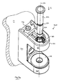
Figure 1 is an exploded perspective view of a hinge leaf sub-assembly in accordance with the present invention, -
Figure 2 is a section view of the hinge leaf sub-assembly offigure 1 along line II-II offigure 1 , -
Figure 3 is a top view of the hinge leaf sub-assembly offigure 1 , -
Figure 4 is a front view of the hinge leaf sub-assembly offigure 1 , -
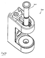
Figure 5 is a perspective view of the hinge leaf sub-assembly offigure 1 , -
Figure 6a is a front view of the hinge leaf sub-assembly offigure 1 in a first configuration, -
Figure 6b is a front view of the hinge leaf sub-assembly offigure 1 in a second configuration, -
Figure 7a is an exploded perspective view of a hinge frame sub-assembly in accordance with the present invention, -
Figure 7b is a perspective view of the hinge frame sub-assembly offigure 7a , -
Figure 8 is an end view of the hinge frame sub-assembly offigure 7a , -
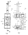
Figure 9 is a section view along IX-IX offigure 9 , -
Figure 10 is a perspective view of an alternative assembly of the hinge leaf sub-assembly offigures 1 to 6b . -
Figure 11 is an exploded perspective view of a second hinge leaf sub-assembly in accordance with the present invention, and -
Figure 12 is a section view of the hinge leaf sub-assembly offigure 11 along line XII-XII offigure 11 . - Referring to
figures 1 to 5 , a doorhinge leaf sub-assembly 100 is shown. The door hingeleaf sub-assembly 100 comprises ahinge leaf 102 having anattachment portion 104 for attachment to a door sash 10 (shown cut away). Theattachment portion 104 comprises anattachment face 106 which abuts thedoor sash 10 when the hinge of which thesub-assembly 100 is a part is in use. Theattachment portion 104 comprises acover 105 visible infigure 3 , and in hidden line infigure 5 . - The sub-assembly 100 comprises a
knuckle 108 extending from theleaf 102 in a direction generally parallel with theattachment face 106. Theknuckle 108 is a collar defining an open bore 110. The open bore 110 is defined by afirst side face 112, asecond side face 114, a first end face 116 and a second end face 118, each joined bycurved faces 120. Theknuckle 108 defines arectangular recess 121 having two locatingpegs 125 projecting therefrom. Theknuckle 108 defines anopen bore 123 through the first end face 116. - The sub-assembly 100 comprises a
bush 122 Thebush 122 is an elongate prismatic body having a firstexternal side face 124 and a secondexternal side face 126 joined by a pair of flat end faces 128, 130. The side faces 124, 126 are generally curved withflats flats bore 132 having apivot axis 134 parallel to the end faces 128, 130. - Each
end face bore pivot axis 134 and in communication with the throughbore 132. - The through
bore 132, as can be seen infigure 2 , comprises acentral neck portion 140 separating a firsttapered portion 142 and a secondtapered portion 144. Each taperedportion bush 122 and defines a locatinggroove - The
bush 122 comprises afirst end cap 150 and asecond end cap 152. The end caps 150, 152 are substantially identical and therefore only theend cap 152 will be described in detail. - The
end cap 152 comprises a hollow shaft portion 154 with aradially projecting tab 155. At one end of the shaft portion 154 there is anelliptical flange 156. A through-bore 158 runs through theend cap 152. - The
hinge sub-assembly 100 is assembled by inserting thebush 122 into the bore 110. It will be noted that thebush 122 is dimensioned such that theflats - The
bush 122 can slide within the bore 110 in direction S (seefigure 2 ) on theflats face 106. - When the
bush 122 is inserted, the end caps 150, 152 are inserted into thetapered portions bore 132. Thetab 155 engages with the locatinggroove 146 to retain the end caps 150, 152 in position with respect to thebush 122. - An
adjustment screw 160 is provided having ahead 162 for receiving a screwdriver, a threaded shaft 164 and a flange 166 therebetween. Thescrew 160 is inserted through the unthreaded bore 123 to engage the threaded bore 136 of thebush 122. The flange 166 abuts the outside surface of theknuckle 108. Thebush 122 is retained from sliding along thepivot axis 134 by theadjustment screw 160. - A
cover plate 168 is then placed over the screw. Thecover plate 168 comprises anaccess bore 170 and two location bores 172, 174 which engage with the locating pegs 125. The access bore 170 has a diameter larger than thehead 162 but smaller than the flange 166 to retain thescrew 160 in place relative to theknuckle 108. - In use, a screwdriver (not shown) can be used to rotate the
screw 160 which, because it is engaged with thebush 122, moves thebush 122 in the direction S. When the hinge is installed, this provides seal compression adjustment (i.e. movement of thedoor sash 10 in a direction perpendicular to the door sash- i.e. away from and towards the door frame). - Turning to
figures 6a and 6b , thehinge sub-assembly 100 is shown attached to a door sash 10 (in hidden line). Thecover 105 is not visible. - The
attachment portion 104 comprises a pair of elongateparallel slots 178 which pass through to the attachment face 106 (seefigure 1 ). Thehinge sub-assembly 100 comprises acarriage 176 on the opposite side of the attachment portion to theattachment face 106. Thecarriage 176 comprises afirst leg 180 and asecond leg 182 which are parallel and spaced. The legs are similar (a mirror image of each other) and as such only theleg 182 will be described. Theleg 182 defines three fixingapertures 184. The fixingapertures 184 are positioned nearer to afirst end 186 than asecond end 188 of the leg. It will be appreciated that thecarriage 176 is therefore asymmetrical. At thesecond end 188 of the leg, a fixing post 190 (seefigure 3 ) projects through theslot 178 to theattachment face 106 and into thedoor sash 10. - The
legs bore 194. Ascrew 196 is provided in thehinge sub-assembly 100, engaged with thebore 194 and the head of thescrew 196 is constrained within theattachment portion 104 such that rotation of thescrew 196 moves thecarriage 176 relative to theattachment portion 104 in a direction C. - When the
hinge sub-assembly 100 is installed onto adoor sash 10, theposts 190 are aligned to a corresponding orifice on thedoor sash 10, and a plurality of screws are fastened through theapertures 184, through theslots 178 to reinforcement of thedoor sash 10. - Different door sash designs may have different structures, and the metal reinforcements to which the
hinge sub-assembly 100 is fastened may be in different positions. In order to facilitate variations in door sash geometry, thecarriage 176 is configured to be reversed- i.e. turned 180 degrees with the first ends 186 and the second ends 188 of thelegs figure 6b . Because thebore 194 is a through-bore, thescrew 196 can engage it from either end. Also, thecarriage 196 is in the shape of an "H" with the grooves made between thelegs screw 196 to afford a full range of motion in either orientation. Although theapertures 184 are asymmetrical in thecarriage 196, the outer profile of thecarriage 196 is symmetrical and therefore reversible. - Turning to
figures 7a to 9 , ahinge sub-assembly 200 is shown, which attaches to adoor frame 12. Referring tofigure 7a , thehinge sub-assembly 200 comprises aknuckle 202 having acentre portion 204, afirst arm 206 and asecond arm 208. Thearms centre portion 204. Each of thearms figure 9 ) which are aligned along ahinge axis 214. - The
hinge sub-assembly 200 comprises afirst insert 216 and asecond insert 218. The inserts are substantially identical and only theinsert 216 will be described here. Theinsert 216 comprises aflange 220 with a projecting shaft 224. The shaft 224 extends into a plurality ofresilient fingers 226 which are radially movable but resile to their original position. Thefingers 226 have radially outwardly extendingtabs 228 at their ends, and some of thefingers 226 have radially inwardly extendingtabs 230. The shaft defines a throughbore 225. - The
inserts bores 210, 212 such that theflanges 220 are facing each other. Thetabs 228 snap onto corresponding features in thearms inserts bores 225 are coaxial with thehinge axis 214 as shown infigure 9 . - The
centre portion 204 comprises a threadedbore 240 proximate thefirst arm 206. Thebore 240 receives a threadedadjustment bolt 242 which can be moved in a direction parallel to thehinge axis 214 by turning. - The
hinge sub-assembly 200 comprises ahinge frame 232. Thehinge frame 232 comprises aplate 234 having a pair of projectingattachment posts 236 and a pair of countersunk fixingholes 238 defined therethrough. The hinge frame is attached to the door frame 12 (seefigure 7a ) by inserting theposts 236 in appropriate recesses and securing in place with screws through the fixing holes 238. - The
hinge frame 232 is slideably mounted in thecentre portion 204 of the sub-assembly 200, and can slide in a direction parallel to thehinge axis 214. Theadjustment bolt 242 abuts thehinge frame 232 and therefore the relative position of theknuckle 202 and thehinge frame 232 may be adjusted. - A
hinge pin 244 is shown. Thehinge pin 244 is generally cylindrical with aflange 246 at afirst end 248. Thehinge pin 244 comprises a first, second and third axially spacedcircumferential grooves - In order to assemble the hinge, the
hinge pin 244 is inserted into thebore 225 of the first insert in an insertion direction I (seefigure 7a ). Thethird groove 254 is engaged by thetabs 230 of thefirst insert 216 to axially retain thepin 244 in the position shown infigures 7b ,8 and 9 such that is does not enter the space between the legs 206,208. - The
leaf sub-assembly 100 and theframe sub-assembly 200 are then aligned with theknuckle 108 of theleaf sub-assembly 100 between thefirst leg 206 and thesecond leg 208 of theframe sub-assembly 200. Theaxes - With the
door sash 10 in position, an axial force is applied to thepin 244 to disengage thetabs 230 from the third groove 254 (thefingers 226 will resile radially outwardly). The pin can then be engaged with theknuckle 108 of theleaf sub-assembly 100 and inserted into thesecond leg 208. Once in position, thethird groove 254 can engage with thetabs 230 of thesecond insert 218 to "click" the pin in place, whilst thefirst groove 250 is engaged by thetabs 230 of thefirst insert 216. In order to secure thepin 244 in position, a grub screw is inserted through the threaded bore 138 (seefigure 2 ) in thebush 122. - It will be noted that as well as retaining the
pin 244 in the position shown infigures 7b ,8 and 9 , the combination of grooves and tabs provides a "click" upon full insertion of thepin 244 to indicate to the user than thepin 244 has been inserted to its full extent. This engagement also prevents thepin 244 from moving axially before it is secured. - When assembled, the hinge can be adjusted in seal compression by rotation of the
adjustment screw 160. Furthermore, the vertical position of the door sash can be adjusted by rotation of thebolt 242. The horizontal position of the door sash can be adjusted by rotation of thescrew 196. All three degrees of freedom are completely separately controlled, and adjustment of one does not influence the others. - Referring to
figures 11 and 12 , a doorhinge leaf sub-assembly 300 is shown. The door hingeleaf sub-assembly 300 is similar to the doorhinge leaf sub-assembly 100 and similar components are numbered 200 greater. - Referring to
figure 11 , a difference between the sub-assembly 100 and the sub-assembly 300 is the existence of anindicator tab 400 projecting radially from the first end-cap 350. Theindicator tab 400 extends past the edge of theknuckle 308 to face the same direction as thescrew 160. - As shown in
figure 12 , when theknuckle 308 is installed between thefirst arm 206 and thesecond arm 208 to rotate about the axis, theindicator tab 400 protrudes between theknuckle 308 and thefirst arm 206 such that it is visible from the side on which thescrew 160 can be adjusted. As such, the installer can determine the position of thebush 322 within theknuckle 308 by the amount thetab 400 protrudes. Thetab 400 is a brightly coloured component so as to contrast with the surrounding componentry. As thetab 400 is integral with theinsert 350, theinsert 350 may be entirely constructed from a brightly coloured plastics material. - The
indicator tab 400 may have measurement lines indicated on it to show the position of thebush 322 within theknuckle 308. - Variations of the above embodiment fall within the scope of the present invention.
- For example, referring to
figure 10 , theleaf sub-assembly 100 may be assembled such that thehead 162 of theadjustment screw 160 protrudes from the front of theknuckle 108. In this configuration, compression adjustment may be performed without opening the door sash first by removing the cover.
Claims (15)
- A domestic door hinge sub-assembly comprising:a hinge knuckle,an attachment portion configured for attachment to a door component,a bush defining a bore for receiving a hinge pin, the bore defining a hinge axis, in which the bush is mounted within the knuckle to be linearly movable relative thereto in a direction substantially perpendicular to the hinge axis, and,an adjustment mechanism arranged between the knuckle and the bush, for selective linear movement of the bush relative to the knuckle in the direction substantially perpendicular to the hinge axis.
- A domestic door hinge sub-assembly according to claim 1 in which the attachment portion is a hinge leaf defining an attachment face for attachment to a planar face of a door sash, and the bush is mounted to be linearly movable in a direction substantially perpendicular to the attachment face.
- A domestic door hinge sub-assembly according to claim 1 in which the attachment portion is a hinge frame defining an attachment face for attachment to a planar face of a door frame, and the bush is mounted to be linearly movable in a direction substantially perpendicular to the attachment face.
- A domestic door hinge sub-assembly according to any of claims 1 to 3 in which the adjustment mechanism comprises a threaded member engaged in a threaded bore in the bush, the threaded member being linearly constrained in the knuckle.
- A domestic door hinge sub-assembly according to claim 4 in which the bush defines a flat end face in which the threaded bore is defined.
- A domestic door hinge sub-assembly according to claim 4 or 5 in which the threaded member comprises a flange, the flange being constrained between a surface of the knuckle and a retention plate mounted to the knuckle.
- A domestic door hinge sub-assembly according to claim 6 in which the threaded member comprises a tool engagement formation, and the retention plate defines an orifice through which the tool engagement formation is accessed by a tool.
- A domestic door hinge sub-assembly according to claim 6 or 7 in which the retention plate defines a plurality of markings for visual indication of the degree of rotational movement of the threaded member.
- A domestic door hinge sub-assembly according to any preceding claim in which the bush is mounted in a slot defined in the knuckle.
- A domestic door hinge sub-assembly according to claim 9 in which the bush defines two opposing side faces, the slot defines two opposing side faces, and the side faces of the bush are arranged to slide along the side faces of the slot.
- A domestic door hinge sub-assembly according to claim 10 in which the bush defines two opposing end faces, in which the end faces and the side faces are joined by curved faces.
- A domestic door hinge sub-assembly according to claim 11 in which the curved faces correspond to interior curved faces of the slot.
- A domestic door hinge sub-assembly according to any preceding claim further comprising an indicator tab moveable with the bush relative to the knuckle in which a part of the indicator tab is positioned proximate an outer surface of the knuckle for indication of the relative position of the knuckle and the bush.
- A domestic door hinge sub-assembly according to claim 13 in which the indicator tab is integral with an end-cap of the bush.
- A domestic door hinge sub-assembly according to claim 13 or claim 14 in which the indicator tab is coloured to contrast with the hinge knuckle.
Applications Claiming Priority (2)
| Application Number | Priority Date | Filing Date | Title |
|---|---|---|---|
| GB0912447A GB0912447D0 (en) | 2009-07-17 | 2009-07-17 | Adjustable hinge |
| GB0921928A GB0921928D0 (en) | 2009-07-17 | 2009-12-16 | Adjustable hinge |
Publications (2)
| Publication Number | Publication Date |
|---|---|
| EP2275631A2 true EP2275631A2 (en) | 2011-01-19 |
| EP2275631A3 EP2275631A3 (en) | 2013-10-02 |
Family
ID=41058119
Family Applications (1)
| Application Number | Title | Priority Date | Filing Date |
|---|---|---|---|
| EP10169715.9A Withdrawn EP2275631A3 (en) | 2009-07-17 | 2010-07-15 | Adjustable hinge |
Country Status (2)
| Country | Link |
|---|---|
| EP (1) | EP2275631A3 (en) |
| GB (2) | GB0912447D0 (en) |
Cited By (8)
| Publication number | Priority date | Publication date | Assignee | Title |
|---|---|---|---|---|
| GB2490124A (en) * | 2011-04-18 | 2012-10-24 | Grouphomesafe Ltd | Hinge permitting adjustment in a vertical, horizontal and compression direction |
| US20130104340A1 (en) * | 2011-10-26 | 2013-05-02 | Josef Hasler | Hinge with adjustment elements and adjustment crown for adjustment elements |
| GB2508248A (en) * | 2012-08-20 | 2014-05-28 | Tianbao Hardware | Hinge with adjustable hinge pin bushing |
| EP2927407A1 (en) * | 2014-04-02 | 2015-10-07 | Heywood Williams Components Limited | Hinge |
| WO2017017093A1 (en) * | 2015-07-27 | 2017-02-02 | Hamberger Industriewerke Gmbh | Articulated assembly and rotary damper |
| CN108104639A (en) * | 2018-01-31 | 2018-06-01 | 佛山市帕客家居用品有限公司 | A kind of adjustable Pinless hinge with guide member of three-dimensional |
| CN110552564A (en) * | 2019-09-30 | 2019-12-10 | 赵崇良 | Self-adaptive hinge |
| CN112377516A (en) * | 2020-10-30 | 2021-02-19 | 张晨 | Hinge and hinge seat thereof |
Family Cites Families (5)
| Publication number | Priority date | Publication date | Assignee | Title |
|---|---|---|---|---|
| DE9206434U1 (en) * | 1992-05-13 | 1993-09-16 | Dr. Hahn GmbH & Co. KG, 41189 Mönchengladbach | Hinge for doors, windows and the like |
| DE4218430A1 (en) * | 1992-06-04 | 1993-12-09 | Schuering Fenstertech | Adjustable hinge for windows or doors |
| GB2383081B (en) * | 2001-12-13 | 2005-06-01 | J K Furnex Ltd | Hinges |
| DE20313635U1 (en) * | 2003-09-03 | 2005-01-13 | Dr. Hahn Gmbh & Co. Kg | Tape for doors, windows or the like |
| DE202006002236U1 (en) * | 2006-02-10 | 2007-06-21 | Dr. Hahn Gmbh & Co. Kg | Tape for doors, windows or the like |
-
2009
- 2009-07-17 GB GB0912447A patent/GB0912447D0/en not_active Ceased
- 2009-12-16 GB GB0921928A patent/GB0921928D0/en not_active Ceased
-
2010
- 2010-07-15 EP EP10169715.9A patent/EP2275631A3/en not_active Withdrawn
Non-Patent Citations (1)
| Title |
|---|
| None |
Cited By (14)
| Publication number | Priority date | Publication date | Assignee | Title |
|---|---|---|---|---|
| GB2490124B (en) * | 2011-04-18 | 2017-03-22 | Era Home Security Ltd | Hinge for a door or the like |
| GB2490124A (en) * | 2011-04-18 | 2012-10-24 | Grouphomesafe Ltd | Hinge permitting adjustment in a vertical, horizontal and compression direction |
| US20130104340A1 (en) * | 2011-10-26 | 2013-05-02 | Josef Hasler | Hinge with adjustment elements and adjustment crown for adjustment elements |
| US8893352B2 (en) * | 2011-10-26 | 2014-11-25 | Josef Hasler | Hinge with adjustment elements and adjustment crown for adjustment elements |
| GB2508248A (en) * | 2012-08-20 | 2014-05-28 | Tianbao Hardware | Hinge with adjustable hinge pin bushing |
| EP2927407A1 (en) * | 2014-04-02 | 2015-10-07 | Heywood Williams Components Limited | Hinge |
| CN104975774A (en) * | 2014-04-02 | 2015-10-14 | 海伍德·威廉姆斯零件有限公司 | Hinge |
| WO2017017093A1 (en) * | 2015-07-27 | 2017-02-02 | Hamberger Industriewerke Gmbh | Articulated assembly and rotary damper |
| DE112016003371B4 (en) | 2015-07-27 | 2022-05-05 | Hamberger Industriewerke Gmbh | Joint arrangement and rotary damper |
| DE112016003371C5 (en) | 2015-07-27 | 2023-06-07 | Hamberger Industriewerke Gmbh | Joint arrangement and rotary damper |
| CN108104639A (en) * | 2018-01-31 | 2018-06-01 | 佛山市帕客家居用品有限公司 | A kind of adjustable Pinless hinge with guide member of three-dimensional |
| CN110552564A (en) * | 2019-09-30 | 2019-12-10 | 赵崇良 | Self-adaptive hinge |
| CN112377516A (en) * | 2020-10-30 | 2021-02-19 | 张晨 | Hinge and hinge seat thereof |
| CN112377516B (en) * | 2020-10-30 | 2022-05-27 | 浙江可传工贸有限公司 | Hinge and hinge seat thereof |
Also Published As
| Publication number | Publication date |
|---|---|
| GB0912447D0 (en) | 2009-08-26 |
| EP2275631A3 (en) | 2013-10-02 |
| GB0921928D0 (en) | 2010-02-03 |
Similar Documents
| Publication | Publication Date | Title |
|---|---|---|
| EP2275631A2 (en) | Adjustable hinge | |
| AU2020100485B4 (en) | Hinge | |
| EP2710212B1 (en) | Piston device for the controlled rotatable movement of doors, shutters or like members | |
| CA2697693C (en) | Adjustable door hinge | |
| EP3510222B1 (en) | Door hinge | |
| US20080104799A1 (en) | Non-Handed Adjustable Hinge Set | |
| EP2166186B1 (en) | An adjustable door or window hinge | |
| EP3458666B1 (en) | System for the rotatable coupling of a closing element and stationary support structure | |
| GB2532904A (en) | Hinges | |
| EP3480398B1 (en) | Connection system for the removable connection of an accessory for windows or doors | |
| GB2490124A (en) | Hinge permitting adjustment in a vertical, horizontal and compression direction | |
| EP1598510B1 (en) | An adjustable door hinge | |
| EP1608831B1 (en) | Hinge | |
| US9689185B2 (en) | Adjustable hinge for vertically hanging panel | |
| US7059020B2 (en) | Hinge for doors and similar construction components | |
| GB2514559A (en) | Improvements in or relating to hinge assemblies | |
| EP1997991A2 (en) | Hinge for doors or windows | |
| EP1828515B1 (en) | Adjustable door hinge | |
| JPH11241557A (en) | Sliding and swinging door device | |
| AU2013101653A4 (en) | Piston device for the controlled rotatable movement of doors, shutters or like members | |
| AU2021107565A4 (en) | Hinge | |
| RU2775117C2 (en) | Flap fittings for piece of furniture, sidewall of furniture case, and piece of furniture with sidewall | |
| WO2020245731A1 (en) | Hinge for the rotatable movement of a door, a leaf or the like and system for fixing the latter to a stationary supporting structure | |
| WO2004067888A1 (en) | Three directional adjustable hinge | |
| CN210013603U (en) | Hinge assembly and associated shutter |
Legal Events
| Date | Code | Title | Description |
|---|---|---|---|
| PUAI | Public reference made under article 153(3) epc to a published international application that has entered the european phase |
Free format text: ORIGINAL CODE: 0009012 |
|
| AK | Designated contracting states |
Kind code of ref document: A2 Designated state(s): AL AT BE BG CH CY CZ DE DK EE ES FI FR GB GR HR HU IE IS IT LI LT LU LV MC MK MT NL NO PL PT RO SE SI SK SM TR |
|
| AX | Request for extension of the european patent |
Extension state: BA ME RS |
|
| PUAL | Search report despatched |
Free format text: ORIGINAL CODE: 0009013 |
|
| AK | Designated contracting states |
Kind code of ref document: A3 Designated state(s): AL AT BE BG CH CY CZ DE DK EE ES FI FR GB GR HR HU IE IS IT LI LT LU LV MC MK MT NL NO PL PT RO SE SI SK SM TR |
|
| AX | Request for extension of the european patent |
Extension state: BA ME RS |
|
| RIC1 | Information provided on ipc code assigned before grant |
Ipc: E05D 7/04 20060101ALN20130829BHEP Ipc: E05D 7/00 20060101AFI20130829BHEP |
|
| STAA | Information on the status of an ep patent application or granted ep patent |
Free format text: STATUS: THE APPLICATION IS DEEMED TO BE WITHDRAWN |
|
| 18D | Application deemed to be withdrawn |
Effective date: 20140403 |
|
| 19U | Interruption of proceedings before grant |
Effective date: 20120123 |
|
| 19W | Proceedings resumed before grant after interruption of proceedings |
Effective date: 20211102 |
|
| STAA | Information on the status of an ep patent application or granted ep patent |
Free format text: STATUS: THE APPLICATION HAS BEEN PUBLISHED |
|
| STAA | Information on the status of an ep patent application or granted ep patent |
Free format text: STATUS: THE APPLICATION IS DEEMED TO BE WITHDRAWN |
|
| R18D | Application deemed to be withdrawn (corrected) |
Effective date: 20220503 |