EP2275299A1 - Operating machine - Google Patents
Operating machine Download PDFInfo
- Publication number
- EP2275299A1 EP2275299A1 EP09729201A EP09729201A EP2275299A1 EP 2275299 A1 EP2275299 A1 EP 2275299A1 EP 09729201 A EP09729201 A EP 09729201A EP 09729201 A EP09729201 A EP 09729201A EP 2275299 A1 EP2275299 A1 EP 2275299A1
- Authority
- EP
- European Patent Office
- Prior art keywords
- driving
- engine
- electric motor
- state
- electric
- Prior art date
- Legal status (The legal status is an assumption and is not a legal conclusion. Google has not performed a legal analysis and makes no representation as to the accuracy of the status listed.)
- Withdrawn
Links
Images


Classifications
-
- B—PERFORMING OPERATIONS; TRANSPORTING
- B60—VEHICLES IN GENERAL
- B60L—PROPULSION OF ELECTRICALLY-PROPELLED VEHICLES; SUPPLYING ELECTRIC POWER FOR AUXILIARY EQUIPMENT OF ELECTRICALLY-PROPELLED VEHICLES; ELECTRODYNAMIC BRAKE SYSTEMS FOR VEHICLES IN GENERAL; MAGNETIC SUSPENSION OR LEVITATION FOR VEHICLES; MONITORING OPERATING VARIABLES OF ELECTRICALLY-PROPELLED VEHICLES; ELECTRIC SAFETY DEVICES FOR ELECTRICALLY-PROPELLED VEHICLES
- B60L50/00—Electric propulsion with power supplied within the vehicle
- B60L50/10—Electric propulsion with power supplied within the vehicle using propulsion power supplied by engine-driven generators, e.g. generators driven by combustion engines
- B60L50/16—Electric propulsion with power supplied within the vehicle using propulsion power supplied by engine-driven generators, e.g. generators driven by combustion engines with provision for separate direct mechanical propulsion
-
- B—PERFORMING OPERATIONS; TRANSPORTING
- B60—VEHICLES IN GENERAL
- B60W—CONJOINT CONTROL OF VEHICLE SUB-UNITS OF DIFFERENT TYPE OR DIFFERENT FUNCTION; CONTROL SYSTEMS SPECIALLY ADAPTED FOR HYBRID VEHICLES; ROAD VEHICLE DRIVE CONTROL SYSTEMS FOR PURPOSES NOT RELATED TO THE CONTROL OF A PARTICULAR SUB-UNIT
- B60W20/00—Control systems specially adapted for hybrid vehicles
- B60W20/10—Controlling the power contribution of each of the prime movers to meet required power demand
- B60W20/13—Controlling the power contribution of each of the prime movers to meet required power demand in order to stay within battery power input or output limits; in order to prevent overcharging or battery depletion
-
- B—PERFORMING OPERATIONS; TRANSPORTING
- B60—VEHICLES IN GENERAL
- B60K—ARRANGEMENT OR MOUNTING OF PROPULSION UNITS OR OF TRANSMISSIONS IN VEHICLES; ARRANGEMENT OR MOUNTING OF PLURAL DIVERSE PRIME-MOVERS IN VEHICLES; AUXILIARY DRIVES FOR VEHICLES; INSTRUMENTATION OR DASHBOARDS FOR VEHICLES; ARRANGEMENTS IN CONNECTION WITH COOLING, AIR INTAKE, GAS EXHAUST OR FUEL SUPPLY OF PROPULSION UNITS IN VEHICLES
- B60K6/00—Arrangement or mounting of plural diverse prime-movers for mutual or common propulsion, e.g. hybrid propulsion systems comprising electric motors and internal combustion engines
- B60K6/20—Arrangement or mounting of plural diverse prime-movers for mutual or common propulsion, e.g. hybrid propulsion systems comprising electric motors and internal combustion engines the prime-movers consisting of electric motors and internal combustion engines, e.g. HEVs
- B60K6/22—Arrangement or mounting of plural diverse prime-movers for mutual or common propulsion, e.g. hybrid propulsion systems comprising electric motors and internal combustion engines the prime-movers consisting of electric motors and internal combustion engines, e.g. HEVs characterised by apparatus, components or means specially adapted for HEVs
- B60K6/36—Arrangement or mounting of plural diverse prime-movers for mutual or common propulsion, e.g. hybrid propulsion systems comprising electric motors and internal combustion engines the prime-movers consisting of electric motors and internal combustion engines, e.g. HEVs characterised by apparatus, components or means specially adapted for HEVs characterised by the transmission gearings
- B60K6/365—Arrangement or mounting of plural diverse prime-movers for mutual or common propulsion, e.g. hybrid propulsion systems comprising electric motors and internal combustion engines the prime-movers consisting of electric motors and internal combustion engines, e.g. HEVs characterised by apparatus, components or means specially adapted for HEVs characterised by the transmission gearings with the gears having orbital motion
-
- B—PERFORMING OPERATIONS; TRANSPORTING
- B60—VEHICLES IN GENERAL
- B60K—ARRANGEMENT OR MOUNTING OF PROPULSION UNITS OR OF TRANSMISSIONS IN VEHICLES; ARRANGEMENT OR MOUNTING OF PLURAL DIVERSE PRIME-MOVERS IN VEHICLES; AUXILIARY DRIVES FOR VEHICLES; INSTRUMENTATION OR DASHBOARDS FOR VEHICLES; ARRANGEMENTS IN CONNECTION WITH COOLING, AIR INTAKE, GAS EXHAUST OR FUEL SUPPLY OF PROPULSION UNITS IN VEHICLES
- B60K6/00—Arrangement or mounting of plural diverse prime-movers for mutual or common propulsion, e.g. hybrid propulsion systems comprising electric motors and internal combustion engines
- B60K6/20—Arrangement or mounting of plural diverse prime-movers for mutual or common propulsion, e.g. hybrid propulsion systems comprising electric motors and internal combustion engines the prime-movers consisting of electric motors and internal combustion engines, e.g. HEVs
- B60K6/42—Arrangement or mounting of plural diverse prime-movers for mutual or common propulsion, e.g. hybrid propulsion systems comprising electric motors and internal combustion engines the prime-movers consisting of electric motors and internal combustion engines, e.g. HEVs characterised by the architecture of the hybrid electric vehicle
- B60K6/46—Series type
-
- B—PERFORMING OPERATIONS; TRANSPORTING
- B60—VEHICLES IN GENERAL
- B60K—ARRANGEMENT OR MOUNTING OF PROPULSION UNITS OR OF TRANSMISSIONS IN VEHICLES; ARRANGEMENT OR MOUNTING OF PLURAL DIVERSE PRIME-MOVERS IN VEHICLES; AUXILIARY DRIVES FOR VEHICLES; INSTRUMENTATION OR DASHBOARDS FOR VEHICLES; ARRANGEMENTS IN CONNECTION WITH COOLING, AIR INTAKE, GAS EXHAUST OR FUEL SUPPLY OF PROPULSION UNITS IN VEHICLES
- B60K6/00—Arrangement or mounting of plural diverse prime-movers for mutual or common propulsion, e.g. hybrid propulsion systems comprising electric motors and internal combustion engines
- B60K6/20—Arrangement or mounting of plural diverse prime-movers for mutual or common propulsion, e.g. hybrid propulsion systems comprising electric motors and internal combustion engines the prime-movers consisting of electric motors and internal combustion engines, e.g. HEVs
- B60K6/42—Arrangement or mounting of plural diverse prime-movers for mutual or common propulsion, e.g. hybrid propulsion systems comprising electric motors and internal combustion engines the prime-movers consisting of electric motors and internal combustion engines, e.g. HEVs characterised by the architecture of the hybrid electric vehicle
- B60K6/48—Parallel type
- B60K6/485—Motor-assist type
-
- B—PERFORMING OPERATIONS; TRANSPORTING
- B60—VEHICLES IN GENERAL
- B60L—PROPULSION OF ELECTRICALLY-PROPELLED VEHICLES; SUPPLYING ELECTRIC POWER FOR AUXILIARY EQUIPMENT OF ELECTRICALLY-PROPELLED VEHICLES; ELECTRODYNAMIC BRAKE SYSTEMS FOR VEHICLES IN GENERAL; MAGNETIC SUSPENSION OR LEVITATION FOR VEHICLES; MONITORING OPERATING VARIABLES OF ELECTRICALLY-PROPELLED VEHICLES; ELECTRIC SAFETY DEVICES FOR ELECTRICALLY-PROPELLED VEHICLES
- B60L1/00—Supplying electric power to auxiliary equipment of vehicles
- B60L1/003—Supplying electric power to auxiliary equipment of vehicles to auxiliary motors, e.g. for pumps, compressors
-
- B—PERFORMING OPERATIONS; TRANSPORTING
- B60—VEHICLES IN GENERAL
- B60L—PROPULSION OF ELECTRICALLY-PROPELLED VEHICLES; SUPPLYING ELECTRIC POWER FOR AUXILIARY EQUIPMENT OF ELECTRICALLY-PROPELLED VEHICLES; ELECTRODYNAMIC BRAKE SYSTEMS FOR VEHICLES IN GENERAL; MAGNETIC SUSPENSION OR LEVITATION FOR VEHICLES; MONITORING OPERATING VARIABLES OF ELECTRICALLY-PROPELLED VEHICLES; ELECTRIC SAFETY DEVICES FOR ELECTRICALLY-PROPELLED VEHICLES
- B60L1/00—Supplying electric power to auxiliary equipment of vehicles
- B60L1/02—Supplying electric power to auxiliary equipment of vehicles to electric heating circuits
-
- B—PERFORMING OPERATIONS; TRANSPORTING
- B60—VEHICLES IN GENERAL
- B60L—PROPULSION OF ELECTRICALLY-PROPELLED VEHICLES; SUPPLYING ELECTRIC POWER FOR AUXILIARY EQUIPMENT OF ELECTRICALLY-PROPELLED VEHICLES; ELECTRODYNAMIC BRAKE SYSTEMS FOR VEHICLES IN GENERAL; MAGNETIC SUSPENSION OR LEVITATION FOR VEHICLES; MONITORING OPERATING VARIABLES OF ELECTRICALLY-PROPELLED VEHICLES; ELECTRIC SAFETY DEVICES FOR ELECTRICALLY-PROPELLED VEHICLES
- B60L1/00—Supplying electric power to auxiliary equipment of vehicles
- B60L1/20—Energy regeneration from auxiliary equipment
-
- B—PERFORMING OPERATIONS; TRANSPORTING
- B60—VEHICLES IN GENERAL
- B60L—PROPULSION OF ELECTRICALLY-PROPELLED VEHICLES; SUPPLYING ELECTRIC POWER FOR AUXILIARY EQUIPMENT OF ELECTRICALLY-PROPELLED VEHICLES; ELECTRODYNAMIC BRAKE SYSTEMS FOR VEHICLES IN GENERAL; MAGNETIC SUSPENSION OR LEVITATION FOR VEHICLES; MONITORING OPERATING VARIABLES OF ELECTRICALLY-PROPELLED VEHICLES; ELECTRIC SAFETY DEVICES FOR ELECTRICALLY-PROPELLED VEHICLES
- B60L3/00—Electric devices on electrically-propelled vehicles for safety purposes; Monitoring operating variables, e.g. speed, deceleration or energy consumption
- B60L3/0023—Detecting, eliminating, remedying or compensating for drive train abnormalities, e.g. failures within the drive train
- B60L3/003—Detecting, eliminating, remedying or compensating for drive train abnormalities, e.g. failures within the drive train relating to inverters
-
- B—PERFORMING OPERATIONS; TRANSPORTING
- B60—VEHICLES IN GENERAL
- B60L—PROPULSION OF ELECTRICALLY-PROPELLED VEHICLES; SUPPLYING ELECTRIC POWER FOR AUXILIARY EQUIPMENT OF ELECTRICALLY-PROPELLED VEHICLES; ELECTRODYNAMIC BRAKE SYSTEMS FOR VEHICLES IN GENERAL; MAGNETIC SUSPENSION OR LEVITATION FOR VEHICLES; MONITORING OPERATING VARIABLES OF ELECTRICALLY-PROPELLED VEHICLES; ELECTRIC SAFETY DEVICES FOR ELECTRICALLY-PROPELLED VEHICLES
- B60L3/00—Electric devices on electrically-propelled vehicles for safety purposes; Monitoring operating variables, e.g. speed, deceleration or energy consumption
- B60L3/0023—Detecting, eliminating, remedying or compensating for drive train abnormalities, e.g. failures within the drive train
- B60L3/0046—Detecting, eliminating, remedying or compensating for drive train abnormalities, e.g. failures within the drive train relating to electric energy storage systems, e.g. batteries or capacitors
-
- B—PERFORMING OPERATIONS; TRANSPORTING
- B60—VEHICLES IN GENERAL
- B60L—PROPULSION OF ELECTRICALLY-PROPELLED VEHICLES; SUPPLYING ELECTRIC POWER FOR AUXILIARY EQUIPMENT OF ELECTRICALLY-PROPELLED VEHICLES; ELECTRODYNAMIC BRAKE SYSTEMS FOR VEHICLES IN GENERAL; MAGNETIC SUSPENSION OR LEVITATION FOR VEHICLES; MONITORING OPERATING VARIABLES OF ELECTRICALLY-PROPELLED VEHICLES; ELECTRIC SAFETY DEVICES FOR ELECTRICALLY-PROPELLED VEHICLES
- B60L3/00—Electric devices on electrically-propelled vehicles for safety purposes; Monitoring operating variables, e.g. speed, deceleration or energy consumption
- B60L3/0023—Detecting, eliminating, remedying or compensating for drive train abnormalities, e.g. failures within the drive train
- B60L3/0061—Detecting, eliminating, remedying or compensating for drive train abnormalities, e.g. failures within the drive train relating to electrical machines
-
- B—PERFORMING OPERATIONS; TRANSPORTING
- B60—VEHICLES IN GENERAL
- B60L—PROPULSION OF ELECTRICALLY-PROPELLED VEHICLES; SUPPLYING ELECTRIC POWER FOR AUXILIARY EQUIPMENT OF ELECTRICALLY-PROPELLED VEHICLES; ELECTRODYNAMIC BRAKE SYSTEMS FOR VEHICLES IN GENERAL; MAGNETIC SUSPENSION OR LEVITATION FOR VEHICLES; MONITORING OPERATING VARIABLES OF ELECTRICALLY-PROPELLED VEHICLES; ELECTRIC SAFETY DEVICES FOR ELECTRICALLY-PROPELLED VEHICLES
- B60L50/00—Electric propulsion with power supplied within the vehicle
- B60L50/40—Electric propulsion with power supplied within the vehicle using propulsion power supplied by capacitors
-
- B—PERFORMING OPERATIONS; TRANSPORTING
- B60—VEHICLES IN GENERAL
- B60L—PROPULSION OF ELECTRICALLY-PROPELLED VEHICLES; SUPPLYING ELECTRIC POWER FOR AUXILIARY EQUIPMENT OF ELECTRICALLY-PROPELLED VEHICLES; ELECTRODYNAMIC BRAKE SYSTEMS FOR VEHICLES IN GENERAL; MAGNETIC SUSPENSION OR LEVITATION FOR VEHICLES; MONITORING OPERATING VARIABLES OF ELECTRICALLY-PROPELLED VEHICLES; ELECTRIC SAFETY DEVICES FOR ELECTRICALLY-PROPELLED VEHICLES
- B60L50/00—Electric propulsion with power supplied within the vehicle
- B60L50/50—Electric propulsion with power supplied within the vehicle using propulsion power supplied by batteries or fuel cells
- B60L50/60—Electric propulsion with power supplied within the vehicle using propulsion power supplied by batteries or fuel cells using power supplied by batteries
- B60L50/61—Electric propulsion with power supplied within the vehicle using propulsion power supplied by batteries or fuel cells using power supplied by batteries by batteries charged by engine-driven generators, e.g. series hybrid electric vehicles
-
- B—PERFORMING OPERATIONS; TRANSPORTING
- B60—VEHICLES IN GENERAL
- B60L—PROPULSION OF ELECTRICALLY-PROPELLED VEHICLES; SUPPLYING ELECTRIC POWER FOR AUXILIARY EQUIPMENT OF ELECTRICALLY-PROPELLED VEHICLES; ELECTRODYNAMIC BRAKE SYSTEMS FOR VEHICLES IN GENERAL; MAGNETIC SUSPENSION OR LEVITATION FOR VEHICLES; MONITORING OPERATING VARIABLES OF ELECTRICALLY-PROPELLED VEHICLES; ELECTRIC SAFETY DEVICES FOR ELECTRICALLY-PROPELLED VEHICLES
- B60L58/00—Methods or circuit arrangements for monitoring or controlling batteries or fuel cells, specially adapted for electric vehicles
- B60L58/10—Methods or circuit arrangements for monitoring or controlling batteries or fuel cells, specially adapted for electric vehicles for monitoring or controlling batteries
- B60L58/12—Methods or circuit arrangements for monitoring or controlling batteries or fuel cells, specially adapted for electric vehicles for monitoring or controlling batteries responding to state of charge [SoC]
-
- B—PERFORMING OPERATIONS; TRANSPORTING
- B60—VEHICLES IN GENERAL
- B60L—PROPULSION OF ELECTRICALLY-PROPELLED VEHICLES; SUPPLYING ELECTRIC POWER FOR AUXILIARY EQUIPMENT OF ELECTRICALLY-PROPELLED VEHICLES; ELECTRODYNAMIC BRAKE SYSTEMS FOR VEHICLES IN GENERAL; MAGNETIC SUSPENSION OR LEVITATION FOR VEHICLES; MONITORING OPERATING VARIABLES OF ELECTRICALLY-PROPELLED VEHICLES; ELECTRIC SAFETY DEVICES FOR ELECTRICALLY-PROPELLED VEHICLES
- B60L58/00—Methods or circuit arrangements for monitoring or controlling batteries or fuel cells, specially adapted for electric vehicles
- B60L58/10—Methods or circuit arrangements for monitoring or controlling batteries or fuel cells, specially adapted for electric vehicles for monitoring or controlling batteries
- B60L58/24—Methods or circuit arrangements for monitoring or controlling batteries or fuel cells, specially adapted for electric vehicles for monitoring or controlling batteries for controlling the temperature of batteries
- B60L58/25—Methods or circuit arrangements for monitoring or controlling batteries or fuel cells, specially adapted for electric vehicles for monitoring or controlling batteries for controlling the temperature of batteries by controlling the electric load
-
- B—PERFORMING OPERATIONS; TRANSPORTING
- B60—VEHICLES IN GENERAL
- B60L—PROPULSION OF ELECTRICALLY-PROPELLED VEHICLES; SUPPLYING ELECTRIC POWER FOR AUXILIARY EQUIPMENT OF ELECTRICALLY-PROPELLED VEHICLES; ELECTRODYNAMIC BRAKE SYSTEMS FOR VEHICLES IN GENERAL; MAGNETIC SUSPENSION OR LEVITATION FOR VEHICLES; MONITORING OPERATING VARIABLES OF ELECTRICALLY-PROPELLED VEHICLES; ELECTRIC SAFETY DEVICES FOR ELECTRICALLY-PROPELLED VEHICLES
- B60L7/00—Electrodynamic brake systems for vehicles in general
- B60L7/10—Dynamic electric regenerative braking
- B60L7/14—Dynamic electric regenerative braking for vehicles propelled by AC motors
-
- B—PERFORMING OPERATIONS; TRANSPORTING
- B60—VEHICLES IN GENERAL
- B60W—CONJOINT CONTROL OF VEHICLE SUB-UNITS OF DIFFERENT TYPE OR DIFFERENT FUNCTION; CONTROL SYSTEMS SPECIALLY ADAPTED FOR HYBRID VEHICLES; ROAD VEHICLE DRIVE CONTROL SYSTEMS FOR PURPOSES NOT RELATED TO THE CONTROL OF A PARTICULAR SUB-UNIT
- B60W10/00—Conjoint control of vehicle sub-units of different type or different function
- B60W10/04—Conjoint control of vehicle sub-units of different type or different function including control of propulsion units
- B60W10/08—Conjoint control of vehicle sub-units of different type or different function including control of propulsion units including control of electric propulsion units, e.g. motors or generators
-
- B—PERFORMING OPERATIONS; TRANSPORTING
- B60—VEHICLES IN GENERAL
- B60W—CONJOINT CONTROL OF VEHICLE SUB-UNITS OF DIFFERENT TYPE OR DIFFERENT FUNCTION; CONTROL SYSTEMS SPECIALLY ADAPTED FOR HYBRID VEHICLES; ROAD VEHICLE DRIVE CONTROL SYSTEMS FOR PURPOSES NOT RELATED TO THE CONTROL OF A PARTICULAR SUB-UNIT
- B60W10/00—Conjoint control of vehicle sub-units of different type or different function
- B60W10/24—Conjoint control of vehicle sub-units of different type or different function including control of energy storage means
- B60W10/26—Conjoint control of vehicle sub-units of different type or different function including control of energy storage means for electrical energy, e.g. batteries or capacitors
-
- B—PERFORMING OPERATIONS; TRANSPORTING
- B66—HOISTING; LIFTING; HAULING
- B66C—CRANES; LOAD-ENGAGING ELEMENTS OR DEVICES FOR CRANES, CAPSTANS, WINCHES, OR TACKLES
- B66C1/00—Load-engaging elements or devices attached to lifting or lowering gear of cranes or adapted for connection therewith for transmitting lifting forces to articles or groups of articles
- B66C1/04—Load-engaging elements or devices attached to lifting or lowering gear of cranes or adapted for connection therewith for transmitting lifting forces to articles or groups of articles by magnetic means
-
- B—PERFORMING OPERATIONS; TRANSPORTING
- B66—HOISTING; LIFTING; HAULING
- B66C—CRANES; LOAD-ENGAGING ELEMENTS OR DEVICES FOR CRANES, CAPSTANS, WINCHES, OR TACKLES
- B66C13/00—Other constructional features or details
- B66C13/18—Control systems or devices
-
- B—PERFORMING OPERATIONS; TRANSPORTING
- B66—HOISTING; LIFTING; HAULING
- B66F—HOISTING, LIFTING, HAULING OR PUSHING, NOT OTHERWISE PROVIDED FOR, e.g. DEVICES WHICH APPLY A LIFTING OR PUSHING FORCE DIRECTLY TO THE SURFACE OF A LOAD
- B66F9/00—Devices for lifting or lowering bulky or heavy goods for loading or unloading purposes
- B66F9/06—Devices for lifting or lowering bulky or heavy goods for loading or unloading purposes movable, with their loads, on wheels or the like, e.g. fork-lift trucks
- B66F9/075—Constructional features or details
- B66F9/20—Means for actuating or controlling masts, platforms, or forks
-
- E—FIXED CONSTRUCTIONS
- E02—HYDRAULIC ENGINEERING; FOUNDATIONS; SOIL SHIFTING
- E02F—DREDGING; SOIL-SHIFTING
- E02F9/00—Component parts of dredgers or soil-shifting machines, not restricted to one of the kinds covered by groups E02F3/00 - E02F7/00
- E02F9/20—Drives; Control devices
-
- H—ELECTRICITY
- H02—GENERATION; CONVERSION OR DISTRIBUTION OF ELECTRIC POWER
- H02J—ELECTRIC POWER NETWORKS; CIRCUIT ARRANGEMENTS OR SYSTEMS FOR SUPPLYING OR DISTRIBUTING ELECTRIC POWER; SYSTEMS FOR STORING ELECTRIC ENERGY
- H02J7/00—Circuit arrangements for charging or discharging batteries or for supplying loads from batteries
-
- H—ELECTRICITY
- H05—ELECTRIC TECHNIQUES NOT OTHERWISE PROVIDED FOR
- H05K—PRINTED CIRCUITS; CASINGS OR CONSTRUCTIONAL DETAILS OF ELECTRIC APPARATUS; MANUFACTURE OF ASSEMBLAGES OF ELECTRICAL COMPONENTS
- H05K7/00—Constructional details common to different types of electric apparatus
- H05K7/20—Modifications to facilitate cooling, ventilating, or heating
- H05K7/2089—Modifications to facilitate cooling, ventilating, or heating for power electronics, e.g. for inverters for controlling motor
- H05K7/20927—Liquid coolant without phase change
-
- B—PERFORMING OPERATIONS; TRANSPORTING
- B60—VEHICLES IN GENERAL
- B60K—ARRANGEMENT OR MOUNTING OF PROPULSION UNITS OR OF TRANSMISSIONS IN VEHICLES; ARRANGEMENT OR MOUNTING OF PLURAL DIVERSE PRIME-MOVERS IN VEHICLES; AUXILIARY DRIVES FOR VEHICLES; INSTRUMENTATION OR DASHBOARDS FOR VEHICLES; ARRANGEMENTS IN CONNECTION WITH COOLING, AIR INTAKE, GAS EXHAUST OR FUEL SUPPLY OF PROPULSION UNITS IN VEHICLES
- B60K1/00—Arrangement or mounting of electrical propulsion units
- B60K1/02—Arrangement or mounting of electrical propulsion units comprising more than one electric motor
-
- B—PERFORMING OPERATIONS; TRANSPORTING
- B60—VEHICLES IN GENERAL
- B60K—ARRANGEMENT OR MOUNTING OF PROPULSION UNITS OR OF TRANSMISSIONS IN VEHICLES; ARRANGEMENT OR MOUNTING OF PLURAL DIVERSE PRIME-MOVERS IN VEHICLES; AUXILIARY DRIVES FOR VEHICLES; INSTRUMENTATION OR DASHBOARDS FOR VEHICLES; ARRANGEMENTS IN CONNECTION WITH COOLING, AIR INTAKE, GAS EXHAUST OR FUEL SUPPLY OF PROPULSION UNITS IN VEHICLES
- B60K6/00—Arrangement or mounting of plural diverse prime-movers for mutual or common propulsion, e.g. hybrid propulsion systems comprising electric motors and internal combustion engines
- B60K6/20—Arrangement or mounting of plural diverse prime-movers for mutual or common propulsion, e.g. hybrid propulsion systems comprising electric motors and internal combustion engines the prime-movers consisting of electric motors and internal combustion engines, e.g. HEVs
-
- B—PERFORMING OPERATIONS; TRANSPORTING
- B60—VEHICLES IN GENERAL
- B60L—PROPULSION OF ELECTRICALLY-PROPELLED VEHICLES; SUPPLYING ELECTRIC POWER FOR AUXILIARY EQUIPMENT OF ELECTRICALLY-PROPELLED VEHICLES; ELECTRODYNAMIC BRAKE SYSTEMS FOR VEHICLES IN GENERAL; MAGNETIC SUSPENSION OR LEVITATION FOR VEHICLES; MONITORING OPERATING VARIABLES OF ELECTRICALLY-PROPELLED VEHICLES; ELECTRIC SAFETY DEVICES FOR ELECTRICALLY-PROPELLED VEHICLES
- B60L2200/00—Type of vehicles
- B60L2200/40—Working vehicles
- B60L2200/42—Fork lift trucks
-
- B—PERFORMING OPERATIONS; TRANSPORTING
- B60—VEHICLES IN GENERAL
- B60L—PROPULSION OF ELECTRICALLY-PROPELLED VEHICLES; SUPPLYING ELECTRIC POWER FOR AUXILIARY EQUIPMENT OF ELECTRICALLY-PROPELLED VEHICLES; ELECTRODYNAMIC BRAKE SYSTEMS FOR VEHICLES IN GENERAL; MAGNETIC SUSPENSION OR LEVITATION FOR VEHICLES; MONITORING OPERATING VARIABLES OF ELECTRICALLY-PROPELLED VEHICLES; ELECTRIC SAFETY DEVICES FOR ELECTRICALLY-PROPELLED VEHICLES
- B60L2210/00—Converter types
- B60L2210/10—DC to DC converters
- B60L2210/12—Buck converters
-
- B—PERFORMING OPERATIONS; TRANSPORTING
- B60—VEHICLES IN GENERAL
- B60L—PROPULSION OF ELECTRICALLY-PROPELLED VEHICLES; SUPPLYING ELECTRIC POWER FOR AUXILIARY EQUIPMENT OF ELECTRICALLY-PROPELLED VEHICLES; ELECTRODYNAMIC BRAKE SYSTEMS FOR VEHICLES IN GENERAL; MAGNETIC SUSPENSION OR LEVITATION FOR VEHICLES; MONITORING OPERATING VARIABLES OF ELECTRICALLY-PROPELLED VEHICLES; ELECTRIC SAFETY DEVICES FOR ELECTRICALLY-PROPELLED VEHICLES
- B60L2210/00—Converter types
- B60L2210/10—DC to DC converters
- B60L2210/14—Boost converters
-
- B—PERFORMING OPERATIONS; TRANSPORTING
- B60—VEHICLES IN GENERAL
- B60L—PROPULSION OF ELECTRICALLY-PROPELLED VEHICLES; SUPPLYING ELECTRIC POWER FOR AUXILIARY EQUIPMENT OF ELECTRICALLY-PROPELLED VEHICLES; ELECTRODYNAMIC BRAKE SYSTEMS FOR VEHICLES IN GENERAL; MAGNETIC SUSPENSION OR LEVITATION FOR VEHICLES; MONITORING OPERATING VARIABLES OF ELECTRICALLY-PROPELLED VEHICLES; ELECTRIC SAFETY DEVICES FOR ELECTRICALLY-PROPELLED VEHICLES
- B60L2210/00—Converter types
- B60L2210/40—DC to AC converters
-
- B—PERFORMING OPERATIONS; TRANSPORTING
- B60—VEHICLES IN GENERAL
- B60L—PROPULSION OF ELECTRICALLY-PROPELLED VEHICLES; SUPPLYING ELECTRIC POWER FOR AUXILIARY EQUIPMENT OF ELECTRICALLY-PROPELLED VEHICLES; ELECTRODYNAMIC BRAKE SYSTEMS FOR VEHICLES IN GENERAL; MAGNETIC SUSPENSION OR LEVITATION FOR VEHICLES; MONITORING OPERATING VARIABLES OF ELECTRICALLY-PROPELLED VEHICLES; ELECTRIC SAFETY DEVICES FOR ELECTRICALLY-PROPELLED VEHICLES
- B60L2240/00—Control parameters of input or output; Target parameters
- B60L2240/10—Vehicle control parameters
- B60L2240/36—Temperature of vehicle components or parts
-
- B—PERFORMING OPERATIONS; TRANSPORTING
- B60—VEHICLES IN GENERAL
- B60L—PROPULSION OF ELECTRICALLY-PROPELLED VEHICLES; SUPPLYING ELECTRIC POWER FOR AUXILIARY EQUIPMENT OF ELECTRICALLY-PROPELLED VEHICLES; ELECTRODYNAMIC BRAKE SYSTEMS FOR VEHICLES IN GENERAL; MAGNETIC SUSPENSION OR LEVITATION FOR VEHICLES; MONITORING OPERATING VARIABLES OF ELECTRICALLY-PROPELLED VEHICLES; ELECTRIC SAFETY DEVICES FOR ELECTRICALLY-PROPELLED VEHICLES
- B60L2240/00—Control parameters of input or output; Target parameters
- B60L2240/40—Drive Train control parameters
- B60L2240/44—Drive Train control parameters related to combustion engines
- B60L2240/441—Speed
-
- B—PERFORMING OPERATIONS; TRANSPORTING
- B60—VEHICLES IN GENERAL
- B60L—PROPULSION OF ELECTRICALLY-PROPELLED VEHICLES; SUPPLYING ELECTRIC POWER FOR AUXILIARY EQUIPMENT OF ELECTRICALLY-PROPELLED VEHICLES; ELECTRODYNAMIC BRAKE SYSTEMS FOR VEHICLES IN GENERAL; MAGNETIC SUSPENSION OR LEVITATION FOR VEHICLES; MONITORING OPERATING VARIABLES OF ELECTRICALLY-PROPELLED VEHICLES; ELECTRIC SAFETY DEVICES FOR ELECTRICALLY-PROPELLED VEHICLES
- B60L2240/00—Control parameters of input or output; Target parameters
- B60L2240/40—Drive Train control parameters
- B60L2240/54—Drive Train control parameters related to batteries
- B60L2240/547—Voltage
-
- B—PERFORMING OPERATIONS; TRANSPORTING
- B60—VEHICLES IN GENERAL
- B60L—PROPULSION OF ELECTRICALLY-PROPELLED VEHICLES; SUPPLYING ELECTRIC POWER FOR AUXILIARY EQUIPMENT OF ELECTRICALLY-PROPELLED VEHICLES; ELECTRODYNAMIC BRAKE SYSTEMS FOR VEHICLES IN GENERAL; MAGNETIC SUSPENSION OR LEVITATION FOR VEHICLES; MONITORING OPERATING VARIABLES OF ELECTRICALLY-PROPELLED VEHICLES; ELECTRIC SAFETY DEVICES FOR ELECTRICALLY-PROPELLED VEHICLES
- B60L2250/00—Driver interactions
- B60L2250/12—Driver interactions by confirmation, e.g. of the input
-
- B—PERFORMING OPERATIONS; TRANSPORTING
- B60—VEHICLES IN GENERAL
- B60L—PROPULSION OF ELECTRICALLY-PROPELLED VEHICLES; SUPPLYING ELECTRIC POWER FOR AUXILIARY EQUIPMENT OF ELECTRICALLY-PROPELLED VEHICLES; ELECTRODYNAMIC BRAKE SYSTEMS FOR VEHICLES IN GENERAL; MAGNETIC SUSPENSION OR LEVITATION FOR VEHICLES; MONITORING OPERATING VARIABLES OF ELECTRICALLY-PROPELLED VEHICLES; ELECTRIC SAFETY DEVICES FOR ELECTRICALLY-PROPELLED VEHICLES
- B60L2250/00—Driver interactions
- B60L2250/22—Driver interactions by presence detection
-
- B—PERFORMING OPERATIONS; TRANSPORTING
- B60—VEHICLES IN GENERAL
- B60L—PROPULSION OF ELECTRICALLY-PROPELLED VEHICLES; SUPPLYING ELECTRIC POWER FOR AUXILIARY EQUIPMENT OF ELECTRICALLY-PROPELLED VEHICLES; ELECTRODYNAMIC BRAKE SYSTEMS FOR VEHICLES IN GENERAL; MAGNETIC SUSPENSION OR LEVITATION FOR VEHICLES; MONITORING OPERATING VARIABLES OF ELECTRICALLY-PROPELLED VEHICLES; ELECTRIC SAFETY DEVICES FOR ELECTRICALLY-PROPELLED VEHICLES
- B60L2250/00—Driver interactions
- B60L2250/24—Driver interactions by lever actuation
-
- B—PERFORMING OPERATIONS; TRANSPORTING
- B60—VEHICLES IN GENERAL
- B60W—CONJOINT CONTROL OF VEHICLE SUB-UNITS OF DIFFERENT TYPE OR DIFFERENT FUNCTION; CONTROL SYSTEMS SPECIALLY ADAPTED FOR HYBRID VEHICLES; ROAD VEHICLE DRIVE CONTROL SYSTEMS FOR PURPOSES NOT RELATED TO THE CONTROL OF A PARTICULAR SUB-UNIT
- B60W20/00—Control systems specially adapted for hybrid vehicles
-
- B—PERFORMING OPERATIONS; TRANSPORTING
- B60—VEHICLES IN GENERAL
- B60W—CONJOINT CONTROL OF VEHICLE SUB-UNITS OF DIFFERENT TYPE OR DIFFERENT FUNCTION; CONTROL SYSTEMS SPECIALLY ADAPTED FOR HYBRID VEHICLES; ROAD VEHICLE DRIVE CONTROL SYSTEMS FOR PURPOSES NOT RELATED TO THE CONTROL OF A PARTICULAR SUB-UNIT
- B60W2510/00—Input parameters relating to a particular sub-units
- B60W2510/06—Combustion engines, Gas turbines
- B60W2510/0638—Engine speed
-
- B—PERFORMING OPERATIONS; TRANSPORTING
- B60—VEHICLES IN GENERAL
- B60W—CONJOINT CONTROL OF VEHICLE SUB-UNITS OF DIFFERENT TYPE OR DIFFERENT FUNCTION; CONTROL SYSTEMS SPECIALLY ADAPTED FOR HYBRID VEHICLES; ROAD VEHICLE DRIVE CONTROL SYSTEMS FOR PURPOSES NOT RELATED TO THE CONTROL OF A PARTICULAR SUB-UNIT
- B60W2510/00—Input parameters relating to a particular sub-units
- B60W2510/24—Energy storage means
- B60W2510/242—Energy storage means for electrical energy
- B60W2510/244—Charge state
-
- B—PERFORMING OPERATIONS; TRANSPORTING
- B60—VEHICLES IN GENERAL
- B60Y—INDEXING SCHEME RELATING TO ASPECTS CROSS-CUTTING VEHICLE TECHNOLOGY
- B60Y2200/00—Type of vehicle
- B60Y2200/10—Road Vehicles
- B60Y2200/15—Fork lift trucks, Industrial trucks
-
- B—PERFORMING OPERATIONS; TRANSPORTING
- B60—VEHICLES IN GENERAL
- B60Y—INDEXING SCHEME RELATING TO ASPECTS CROSS-CUTTING VEHICLE TECHNOLOGY
- B60Y2200/00—Type of vehicle
- B60Y2200/20—Off-Road Vehicles
- B60Y2200/25—Track vehicles
-
- B—PERFORMING OPERATIONS; TRANSPORTING
- B60—VEHICLES IN GENERAL
- B60Y—INDEXING SCHEME RELATING TO ASPECTS CROSS-CUTTING VEHICLE TECHNOLOGY
- B60Y2200/00—Type of vehicle
- B60Y2200/40—Special vehicles
- B60Y2200/41—Construction vehicles, e.g. graders, excavators
-
- B—PERFORMING OPERATIONS; TRANSPORTING
- B60—VEHICLES IN GENERAL
- B60Y—INDEXING SCHEME RELATING TO ASPECTS CROSS-CUTTING VEHICLE TECHNOLOGY
- B60Y2200/00—Type of vehicle
- B60Y2200/40—Special vehicles
- B60Y2200/41—Construction vehicles, e.g. graders, excavators
- B60Y2200/412—Excavators
-
- B—PERFORMING OPERATIONS; TRANSPORTING
- B60—VEHICLES IN GENERAL
- B60Y—INDEXING SCHEME RELATING TO ASPECTS CROSS-CUTTING VEHICLE TECHNOLOGY
- B60Y2400/00—Special features of vehicle units
- B60Y2400/11—Electric energy storages
- B60Y2400/114—Super-capacities
-
- Y—GENERAL TAGGING OF NEW TECHNOLOGICAL DEVELOPMENTS; GENERAL TAGGING OF CROSS-SECTIONAL TECHNOLOGIES SPANNING OVER SEVERAL SECTIONS OF THE IPC; TECHNICAL SUBJECTS COVERED BY FORMER USPC CROSS-REFERENCE ART COLLECTIONS [XRACs] AND DIGESTS
- Y02—TECHNOLOGIES OR APPLICATIONS FOR MITIGATION OR ADAPTATION AGAINST CLIMATE CHANGE
- Y02T—CLIMATE CHANGE MITIGATION TECHNOLOGIES RELATED TO TRANSPORTATION
- Y02T10/00—Road transport of goods or passengers
- Y02T10/60—Other road transportation technologies with climate change mitigation effect
- Y02T10/62—Hybrid vehicles
-
- Y—GENERAL TAGGING OF NEW TECHNOLOGICAL DEVELOPMENTS; GENERAL TAGGING OF CROSS-SECTIONAL TECHNOLOGIES SPANNING OVER SEVERAL SECTIONS OF THE IPC; TECHNICAL SUBJECTS COVERED BY FORMER USPC CROSS-REFERENCE ART COLLECTIONS [XRACs] AND DIGESTS
- Y02—TECHNOLOGIES OR APPLICATIONS FOR MITIGATION OR ADAPTATION AGAINST CLIMATE CHANGE
- Y02T—CLIMATE CHANGE MITIGATION TECHNOLOGIES RELATED TO TRANSPORTATION
- Y02T10/00—Road transport of goods or passengers
- Y02T10/60—Other road transportation technologies with climate change mitigation effect
- Y02T10/70—Energy storage systems for electromobility, e.g. batteries
-
- Y—GENERAL TAGGING OF NEW TECHNOLOGICAL DEVELOPMENTS; GENERAL TAGGING OF CROSS-SECTIONAL TECHNOLOGIES SPANNING OVER SEVERAL SECTIONS OF THE IPC; TECHNICAL SUBJECTS COVERED BY FORMER USPC CROSS-REFERENCE ART COLLECTIONS [XRACs] AND DIGESTS
- Y02—TECHNOLOGIES OR APPLICATIONS FOR MITIGATION OR ADAPTATION AGAINST CLIMATE CHANGE
- Y02T—CLIMATE CHANGE MITIGATION TECHNOLOGIES RELATED TO TRANSPORTATION
- Y02T10/00—Road transport of goods or passengers
- Y02T10/60—Other road transportation technologies with climate change mitigation effect
- Y02T10/7072—Electromobility specific charging systems or methods for batteries, ultracapacitors, supercapacitors or double-layer capacitors
-
- Y—GENERAL TAGGING OF NEW TECHNOLOGICAL DEVELOPMENTS; GENERAL TAGGING OF CROSS-SECTIONAL TECHNOLOGIES SPANNING OVER SEVERAL SECTIONS OF THE IPC; TECHNICAL SUBJECTS COVERED BY FORMER USPC CROSS-REFERENCE ART COLLECTIONS [XRACs] AND DIGESTS
- Y02—TECHNOLOGIES OR APPLICATIONS FOR MITIGATION OR ADAPTATION AGAINST CLIMATE CHANGE
- Y02T—CLIMATE CHANGE MITIGATION TECHNOLOGIES RELATED TO TRANSPORTATION
- Y02T10/00—Road transport of goods or passengers
- Y02T10/60—Other road transportation technologies with climate change mitigation effect
- Y02T10/72—Electric energy management in electromobility
Definitions
- the present invention relates to a working machine.
- a working machine with a motor generator for assisting an engine includes a storage battery, such as a capacitor, for supplying electric power to the motor generator and charging regenerative power. Since such a capacitor is used in an environment where charging and discharging are repeatedly performed, various studies for increasing the life of the capacitor are in progress.
- a discharge setting value is set for the voltage value of the capacitor and discharging is performed to lower the voltage value of the capacitor to the discharge setting value or lower if the charge voltage of the capacitor exceeds the discharge setting value when the working machine stops working, so that the life of the capacitor can be increased.
- Discharged electric power is stored in an auxiliary battery (for examples, see Patent Document 1).
- a working machine related to the present invention includes : a first electric motor used for work; a second electric motor used for applications other than work; a first inverter circuit connected to the first electric motor; a second inverter circuit connected to the second electric motor; a battery connected to the first and second inverter circuits; and a control unit that drives the first and second inverter circuits.
- the control unit has a discharge mode to discharge electric power stored in the battery, and discharges the battery by stopping the first inverter circuit while driving the second inverter circuit in order to make the second electric motor perform electric operation in the discharge mode.
- the first electric motor is an electric motor for operation driven by an operation of an operator.
- One end of the first inverter circuit is connected to a terminal of the electric motor for operation.
- the battery is connected to the other end of the first inverter circuit through a DC voltage converter.
- a coolant circulation system which is provided to cool the first inverter circuit and the DC voltage converter and which includes a pump to circulate coolant and an electric motor to cool as the second electric motor that drives the pump, is further provided.
- the second inverter circuit is connected between the electric motor to cool and the DC voltage converter.
- the control unit drives the first and second inverter circuits and the DC voltage converter.
- the control unit discharges the battery by stopping the first inverter circuit while driving the second inverter circuit in order to make the electric motor to cool consume electric power in the discharge mode.
- the DC voltage converter has a step-up and step-down type switching control system including switching elements for step-up and step-down and a diode connected in parallel to each of the switching elements.
- the control unit does not drive the switching elements in the discharge mode.
- an internal combustion engine a motor generator which is connected to the internal combustion engine and which generates electric power with the driving force of the internal combustion engine and assists the driving force of the internal combustion engine with its own driving force, and a third inverter circuit connected between the motor generator and the DC voltage converter are further provided.
- the control unit stops the third inverter circuit in the discharge mode.
- the coolant circulation system may further cool the electric motor for operation.
- the second electric motor is a motor generator to assist an engine.
- the battery performs supplying of electric power to the motor generator or charging of regenerative power.
- the second inverter circuit performs driving control of the motor generator.
- the control unit includes a driving level determining section that determines a driving level of the engine or the operating element. The second inverter circuit performs electric operation of the motor generator when the driving level determining section determines that the driving level of the engine or the operating element is equal to or lower than a predetermined level.
- the second inverter circuit may perform electric driving of the motor generator so that a state of charge of the battery is maintained at a predetermined level or higher.
- the driving level determining section may be configured to determine the driving level of the engine on the basis of an operating state of the operating element, determine the driving level of the engine according to the number of revolutions of the engine, determine the driving level of the operating element according to the amount of operation input to an operating device of the operating element, determine the driving level of the engine or the operating element according to an operating state of a gate lock lever to prohibit a driver from leaving a driver's seat, or determine the driving level of the engine or the operating element according to an operation position of an ignition switch.
- a plurality of operating elements including a motor generator to assist an engine and a capacitor, which performs supplying of electric power to the motor generator or charging of regenerative power, is driven by an electromotive force or a hydraulic force.
- a driving control section which performs driving control of the motor generator, and a driving level determining section, which determines a driving level of the engine or the operating element, are provided. The driving control section performs electric operation of the motor generator when the driving level determining section determines that the driving level of the engine or the operating element is equal to or lower than a predetermined level.
- the driving control section may perform electric driving of the motor generator using electric power stored in the capacitor.
- the driving control section may perform electric driving of the motor generator so that a state of charge of the capacitor is maintained at a predetermined level or higher.
- the driving level determining section is configured to determine the driving level of the engine on the basis of an operating state of the operating element, and the driving control section may perform electric operation of the motor generator when the driving level determining section determines that the driving level of the engine is equal to or lower than a predetermined level on the basis of the operating state of the operating element.
- the driving level determining section is configured to determine the driving level of the engine according to the number of revolutions of the engine, and the driving control section may perform electric operation of the motor generator when the driving level determining section determines that the driving level of the engine is equal to or lower than a predetermined level on the basis of the number of revolutions of the engine.
- the driving level determining section is configured to determine the driving level of the operating element according to the amount of operation input to an operating device of the operating element, and the driving control section may perform electric operation of the motor generator when the driving level determining section determines that the driving level of the operating element is equal to or lower than a predetermined level on the basis of the amount of operation input to the operating device of the operating element.
- the driving level determining section is configured to determine the driving level of the engine or the operating element according to an operating state of a gate lock lever to prohibit a driver from leaving a driver's seat, and the driving control section may perform electric operation of the motor generator when the driving level determining section determines that the driving level of the engine or the operating element is equal to or lower than a predetermined level on the basis of the operating state of the gate lock lever.
- the driving level determining section is configured to determine the driving level of the engine or the operating element according to an operation position of an ignition switch, and the driving control section may perform electric operation of the motor generator when the driving level determining section determines that the driving level of the engine or the operating element is equal to or lower than a predetermined level on the basis of the operation position of the ignition switch.
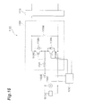
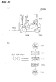
- Fig 1 is a side view showing a hybrid type construction machine of a first example.
- an upper revolving body 3 On a base carrier 1 of the hybrid type construction machine, an upper revolving body 3 is mounted with a revolving mechanism 2.
- a boom 4, an arm 5, a lifting magnet 6, a boom cylinder 7 for hydraulic driving of these components, an arm cylinder 8, and a bucket cylinder 9, a cabin 10, and a power source are mounted in the upper revolving body 3.
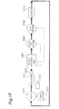
- Fig. 2 is a block diagram showing the configuration of a hybrid type construction machine of the first example.
- a mechanical power system, a high-pressure hydraulic line, a pilot line, and an electric driving and control system are indicated by a double line, a solid line, a broken line, and a one-dot chain line, respectively.
- Both an engine 11 as a mechanical driving section and a motor generator 12 (second electric motor) as an assistant driving section are connected to an input shaft of a decelerator 13 as a force multiplying mechanism.
- a main pump 14 and a pilot pump 15 are connected to an output shaft of the decelerator 13.
- a control valve 17 is connected to the main pump 14 through a high-pressure hydraulic line 16.
- the control valve 17 is a control device which controls the hydraulic system in the construction machine of the first example. Hydraulic motors 1A (for right) and 1B (for left) for the base carrier 1, the boom cylinder 7, the arm cylinder 8, and the bucket cylinder 9 are connected to the control valve 17 through high-pressure hydraulic lines.
- a capacitor that is, a capacitor 19 as a battery is connected to the motor generator 12 through an inverter 18A as a second inverter circuit (driving control section) and a step-up and step-down converter 30.
- the inverter 18A and the step-up and step-down converter 30 are connected to each other through a DC bus 40.
- a lifting magnet 6 is connected to the DC bus 40 through an inverter 18B, and an electric motor 21 (first electric motor) for rotation is connected to the DC bus 40 through an inverter 20 as a first inverter circuit.
- the DC bus 40 is provided for transmission of electric power between the capacitor 19, the motor generator 12, and the electric motor 21 for rotation.
- a DC bus voltage detecting section 41 for detecting the voltage value (hereinafter, referred to as a DC bus voltage value) of the DC bus 40 is provided in the DC bus 40.
- the detected DC bus voltage value is input to a controller 50 as a control unit.
- a capacitor voltage detecting section 31 for detecting the capacitor voltage value and a capacitor current detecting section 32 for detecting the capacitor current value are provided in the capacitor 19.
- the capacitor voltage value detected by the capacitor voltage detecting section 31 is input to the controller 50.
- the capacitor current value detected by the capacitor current detecting section 32 is input to the controller 50.
- a resolver 22, a mechanical brake 23, and a rotation speed reduction mechanism 24 are connected to a rotary shaft 21A of the electric motor 21 for rotation.
- an operating device 26 is connected to the pilot pump 15 through a pilot line 25.
- the operating device 26 is an operating device for operating the electric motor 21 for rotation, the base carrier 1, the boom 4, the arm 5, and the bucket 6, and includes levers 26A and 26B and a pedal 26C.
- the lever 26A is a lever for operating the electric motor 21 for rotation and the arm 5, and is provided near the driver's seat of the upper revolving body 3.
- the lever 26B is a lever for operating the boom 4 and the bucket 6, and is provided near the driver's seat.
- the pedal 26C is a pair of pedals for operating the base carrier 1, and is provided below the feet in the driver's seat.
- the operating device 26 converts the oil pressure (oil pressure on the primary side), which is supplied through the pilot line 25, into the oil pressure (oil pressure on the secondary side) according to the amount of operation of a driver and outputs it.
- the oil pressure on the secondary side output from the operating device 26 is supplied to the control valve 17 through a hydraulic line 27 and is also detected by a pressure sensor 29.
- controller 50 which performs driving control of an electric system of the construction machine of the first example is connected to the pressure sensor 29.
- Such a construction machine of the first example is a hybrid type construction machine which has the engine 11, the motor generator 12, and the electric motor 21 for rotation as power sources. These power sources are mounted in the upper revolving body 3 shown in Fig. 1 .
- Fig. 1 a construction machine of the first example
- the engine 11 is an internal combustion engine formed by a diesel engine, for example, and the output shaft is connected to one input shaft of the decelerator 13.
- the engine 11 works all the time during the operation of the construction machine.
- the motor generator 12 is an electric motor both electric (assistant) operation and power generation operation of which are possible.
- a motor generator which is AC-driven by the inverter 20 is shown as the motor generator 12.
- the motor generator 12 may be formed by an IPM (Interior Permanent Magnetic) motor in which a magnet is embedded in a rotor.
- IPM Interior Permanent Magnetic
- the rotary shaft of the motor generator 12 is connected to the other input shaft of the decelerator 13.
- the decelerator 13 has two input shafts and one output shaft.
- a driving shaft of the engine 11 and a driving shaft of the motor generator 12 are connected to each of the two input shafts.
- a driving shaft of the main pump 14 is connected to the output shaft.
- the motor generator 12 performs electric (assistant) operation so that the driving force of the motor generator 12 is transmitted to the main pump 14 through the output shaft of the decelerator 13. Then, driving of the engine 11 is assisted.
- the motor generator 12 performs power generation by the power generation operation. Switching between electric (assistant) operation and power generation operation of the motor generator 12 is performed according to the load of the engine 11 or the like by the controller 50.
- the main pump 14 is a pump which generates oil pressure for supplying to the control valve 17. This oil pressure is supplied to drive each of the hydraulic motors 1A and 1B, the boom cylinder 7, the arm cylinder 8, and the bucket cylinder 9 through the control valve 17.
- a sensor 14A which detects the amount of discharge and pressure of the pressure oil is provided in the main pump 14. A signal indicating the amount of discharge and pressure of the pressure oil which have been detected is input to the controller 50.
- the pilot pump 15 is a pump which generates pilot pressure required for a hydraulic operation system.
- the configuration of the hydraulic operation system will be described later.
- the control valve 17 is a hydraulic control device which controls hydraulic driving of the hydraulic motors 1A and 1B, the boom cylinder 7, the arm cylinder 8, and the bucket cylinder 9 for the base carrier 1, which are connected through a high-pressure hydraulic line, by controlling the oil pressure supplied to each of them according to the operation input of a driver.
- the inverter 18A is provided between the motor generator 12 and the step-up and step-down converter 30 as described above, and performs operation control of the motor generator 12 according to a command from the controller 50. Accordingly, when the inverter 18A makes the motor generator 12 perform electric operation, required electric power is supplied from the capacitor 19 and the step-up and step-down converter 30 to the motor generator 12 through the DC bus 40. In addition, when the inverter 18A makes the motor generator 12 perform power generation operation, electric power generated by the motor generator 12 is charged to the capacitor 19 through the DC bus 40 and the step-up and step-down converter 30.
- the inverter 18B is provided between the lifting magnet 6 and the step-up and step-down converter 30, and supplies the electric power requested to the lifting magnet 6 from the DC bus 40 according to a command from the controller 50 when turning on an electromagnet. In addition, when turning off the electromagnet, the inverter 18B supplies the regenerated electric power to the DC bus 40.
- the lifting magnet 6 includes an electromagnet, which generates a magnetic force for adsorbing a metal material magnetically, and receives electric power from the DOC bus 40 through the inverter 18B.
- the capacitor 19 is connected to the inverters 18A, 18B, and 20 through the step-up and step-down converter 30.
- the capacitor 19 is a power source which supplies electric power required for electric (assistant) operation or power operation when at least one of the electric (assistant) operation of the motor generator 12 and the power operation of the electric motor 21 for rotation is performed and which stores the electric power generated by power generation operation or regenerative operation as electrical energy when at least one of the power generation operation of the motor generator 12 and the regenerative operation of the electric motor 21 for rotation is performed.
- the capacitor 19 is formed by a group of condensers.
- Charging and discharging control of the capacitor 19 is performed by the step-up and step-down converter 30 on the basis of the charge state of the capacitor 19, the operation state (electric (assistant) operation or power generation operation) of the motor generator 12, the driving state of the lifting magnet 6, and the operation state (power operation or regenerative operation) of the electric motor 21 for rotation.
- a switching control between a step-up operation and a step-down operation of the step-up and step-down converter 30 is performed by the controller 50 on the basis of the capacitor voltage value detected by the capacitor voltage detecting section 31, the capacitor current value detected by the capacitor current detecting section 32, and DC bus voltage value detected by the DC bus voltage detecting section 41.
- the inverter 20 is provided between the electric motor 21 for rotation and the step-up and step-down converter 30 as described above and performs operation control of the electric motor 21 for rotation according to a command from the controller 50. Accordingly, when the inverter controls the power operation of the electric motor 21 for rotation, required electric power is supplied from the capacitor 19 to the electric motor 21 for rotation through the step-up and step-down converter 30. In addition, when the electric motor 21 for rotation performs regenerative operation, electric power generated by the electric motor 21 for rotation is charged to the capacitor 19 through the step-up and step-down converter 30.
- the example in Fig. 2 shows that electric motor for rotation (one set) and an inverter (one set), other magnet mechanisms or driving sections other than a rotating mechanism section may be provided so that a plurality of electric motors and a plurality of inverters are connected to the DC bus 40.
- step-up and step-down converter 30 One side of the step-up and step-down converter 30 is connected to the motor generator 12, the lifting magnet 6, and the electric motor 21 for rotation through the DC bus 40, and the other side of the step-up and step-down converter 30 is connected to the capacitor 19.
- the step-up and step-down converter 30 performs control for switching of step-up operation and step-down operation so that the DC bus voltage value falls within a fixed range.
- the motor generator 12 performs an electric (assistant) operation, it is necessary to supply electric power to the motor generator 12 through the inverter 18A. Accordingly, it is necessary to increase the DC bus voltage value.
- the lifting magnet 6 it is necessary to supply electric power to the lifting magnet 6 through the inverter 18B. Accordingly, the DC bus voltage value is increased according to the electric power supplied to the lifting magnet 6.
- Such a switching of step-up operation and step-down operation is also the same for the power generation and the regenerative operation of the electric motor 21 for rotation.
- the operation state of the motor generator 12 is changed according to the load condition of the engine 11 and the operation state of the electric motor 21 for rotation is changed according to the rotational operation of the upper revolving body 3. Accordingly, a situation may occur in which one of the motor generator 12 and the electric motor 21 for rotation performs electric (assistant) operation or power operation and the other one performs power generation operation or regenerative operation.
- the electromagnet of the lifting magnet 6 is turned on/off according to the working conditions.
- the step-up and step-down converter 30 performs switching between a step-up operation and a step-down operation according to the operation state (driving state) of the motor generator 12, the power generator 30, and the lifting magnet 6 such that the voltage value of the DC bus 40 falls within a fixed range.
- the capacitor voltage detecting section 31 is a voltage detecting section detecting the voltage value of the capacitor 19 and is used to detect the charge state of a battery.
- the detected capacitor voltage value is input to the controller 50 and is used to perform switching control of a step-up operation and a step-down operation of the step-up and step-down converter 30.
- the capacitor current detecting section 32 is a current detecting section for detecting the current value of the capacitor 19.
- the capacitor current value is detected with a current, which flows from the capacitor 19 to the step-up and step-down converter 30, as a positive value.
- the detected capacitor current value is input to the controller 50 and is used to perform switching control of a step-up operation and a step-down operation of the step-up and step-down converter 30.
- the DC bus 40 is provided between the three inverters 18A, 18B, and 20 and the step-up and step-down converter, and is configured such that transmission of electric power between the capacitor 19, the motor generator 12, the lifting magnet 6, and the electric motor 21 for rotation is possible.
- the DC bus voltage detecting section 41 is a voltage detecting section for detecting the DC bus voltage value.
- the detected DC bus voltage value is input to the controller 50 and is used to perform switching control of a step-up operation and a step-down operation for making the DC bus voltage value fall within a fixed range.
- the electric motor 21 for rotation can be an electric motor both power operation and regenerative operation of which are possible, and is provided to drive the rotary mechanism 2 of the upper revolving body 3.
- torque of the rotational driving force of the electric motor 21 for rotation is amplified by the speed reduction mechanism 24, and the upper revolving body 3 performs rotational operation by acceleration and deceleration control.
- the number of revolutions is increased in the speed reduction mechanism 24 and it is transmitted to the electric motor 21 for rotation. This can generate the regenerative power.
- an electric motor which is AC-driven by the inverter 20 using a PWM (Pulse Width Modulation) control signal is shown as the electric motor 21 for rotation.
- the electric motor 21 for rotation may be formed using a magnet embedded type IPM motor. In this case, since the larger induced electromotive force can be generated, electric power generated by the electric motor 21 for rotation at the time of regeneration can be increased.
- the resolver 22 is a sensor which detects the rotation position and the rotation angle of the rotary shaft 21A of the electric motor 21 for rotation, and is configured to detect the rotation angle and the rotation direction of the rotary shaft 21A by detecting a difference between the rotation position of the rotary shaft 21A before rotation of the electric motor 21 for rotation and the rotation position after left rotation or right rotation by mechanical connection with the electric motor 21 for rotation. By detecting the rotation angle of the rotary shaft 21A of the electric motor 21 for rotation, the rotation angle and the rotation direction of the rotary mechanism 2 are derived. Moreover, although a form in which the resolver 22 is fixed is shown in Fig. 2 , it is also possible to adopt an inverter control method in which a rotary sensor of an electric motor is not used.
- the mechanical brake 23 is a braking device which generates a mechanical braking force and stops the rotary shaft 21A of the electric motor 21 for rotation mechanically. Switching between braking and the release of braking of the mechanical brake 23 is performed by an electromagnetic switch. This switching is performed by the controller 50.
- the rotation speed reduction mechanism 24 is a decelerator which reduces the rotation speed of the rotary shaft 21A of the electric motor 21 for rotation and mechanically transmits it to the rotary mechanism 2. Accordingly, at the time of power operation, torque of the electric motor 21 for rotation is increased so that larger torque can be transmitted to a revolving body. In contrast, at the time of regenerative operation, the number of revolutions occurring in the revolving body is increased so that a greater number of rotational operations are generated in the electric motor 21 for rotation.
- the rotary mechanism 2 can rotate in a state where the mechanical brake 23 of the electric motor 21 for rotation is released, so that the upper revolving body 3 rotates in the left or right direction.
- the operating device 26 is an operating device for operating the electric motor 21 for rotation, the base carrier 1, she boom 4, the arm 5, and the lifting magnet 6, and is operated by a driver of the hybrid type construction machine.
- the operating device 26 converts the oil pressure (oil pressure on the primary side), which is supplied through the pilot line 25, into the oil pressure (oil pressure on the secondary side) according to the amount of operation of a driver and outputs it.
- the oil pressure on the secondary side output from the operating device 26 is supplied to the control valve 17 through the hydraulic line 27 and is also detected by a pressure sensor 29.
- the control valve 17 is driven through the hydraulic line 27. Then, since the oil pressure in the hydraulic motors 1A and 1B, the boom cylinder 7, the arm cylinder 8, and the bucket cylinder 9 is controlled, the base carrier 1, the boom 4, the arm 5, and the lifting magnet 6 are driven.
- the hydraulic line 27 supplies the oil pressure, which is required for driving of the hydraulic motors 1A and 1B, the boom cylinder 7, the arm cylinder 8, and the bucket cylinder 9, to the control valve.
- the pressure sensor 29 as a section which detects an operation for rotation detects the amount of operation as a change in the oil pressure in a hydraulic line 28.
- the pressure sensor 29 outputs an electrical signal indicating the oil pressure in the hydraulic line 28.
- the electrical signal is input to the controller 50 and is used for driving control of the electric motor 21 for rotation.
- a pressure sensor as a lever handling detecting section is described in the first example, it is also possible to use a sensor which reads the amount of operation for rotating the rotary mechanism 2, which is input to the operating device 26, as an electrical signal as it is.
- the controller 50 is a control device which performs driving control of the hybrid type construction machine of the first example and is formed by an arithmetic processing unit including a CPU and an internal memory.
- the controller 50 is a device realized when the CPU executes a program for driving control stored in the internal memory.
- a controller 50 is a control device for performing operation control of the engine 11, operation control (switching of electric (assistant) operation and power generation operation) of the motor generator 12, charging and discharging control of the capacitor 19 which is realized by performing driving control of the step-up and step-down converter 30, and driving control of the electric motor 21 for rotation.
- the driving control of the electric motor 21 for rotation is executed by converting a signal input from the pressure sensor 29 (signal indicating the amount of operation for rotating the rotary mechanism 2 which is input to the operating device 26) into a speed command by means of the controller 50 and performing driving control of the electric motor 21 for rotation using the speed command.
- the controller 50 as a control unit includes a driving level determining section.
- the controller 50 performs switching control between a step-up operation and a step-down operation of the step-up and step-down converter 30 on the basis of the charge state of the capacitor 19, the operation state (electric (assistant) operation or power generation operation) of the motor generator 12, and the operation state (power operation or regenerative operation) of the electric motor 21 for rotation, thereby performing charging and discharging control of the capacitor 19.
- a switching control between a step-up operation and a step-down operation of the step-up and step-down converter 30 is performed on the basis of the capacitor voltage value detected by the capacitor voltage detecting section 31, the capacitor current value detected by the capacitor current detecting section 32, and DC bus voltage value detected by the DC bus voltage detecting section 41.
- the operation control of the engine 11 includes not only control of the amount of fuel injection according to the load condition of the engine 11 but also control of start and end of the engine 11.
- the controller 50 monitors the oil pressure of pressure oil detected by the sensor 14A, the control command value transmitted to the inverter 18B, and the control command value transmitted to the inverter 20.
- an increase in the oil pressure of pressure oil detected by the sensor 14A means that any of the work elements of a hydraulic system (hereinafter, the traveling motors 1A and 1B, the boom cylinder 7, the arm cylinder 8, and the bucket cylinder 9 are collectively called a "work element of a hydraulic system") connected to the control valve 17 has been driven. Accordingly, it is possible to detect the driving of a work element of a hydraulic system by monitoring the increase in the oil pressure.
- driving of the lifting magnet 6 can be detected by monitoring the control command value transmitted to the inverter 18B.
- power operation of the electric motor 21 for rotation can be detected by monitoring the control command value transmitted to the inverter 20.
- the controller 50 holds the threshold values for monitoring the oil pressure of pressure oil detected by the sensor 14A, the control command value transmitted to the inverter 18B, and the control command value transmitted to the inverter 20.
- the controller 50 detects driving of an operating element of the hydraulic system, driving of the lifting magnet 6, and power operation of the electric motor 21 for rotation.
- the state of charge (SOC) of the capacitor 19 immediately after the start of operation (before operation) is set to 70%.
- SOC state of charge
- the state of charge (SOC) increases to 85%.
- the state of charge (SOC) is reduced to 70%.
- the reason why the state of charge (SOC) is set to 70% when reducing the state of charge (SOC) is that a certain amount of electric power is immediately needed when driving at least one of the operating element of the hydraulic system, the lifting magnet 6, and the electric motor 21 for rotation.
- the state of charge (SOC) is set low and the responsiveness which does not cause a problem in the work is secured. That is, the minimum state of charge is set in advance on the basis of starting responsiveness of a driving section.
- the reason why the state of charge (SOC) is set to 85% when increasing the state of charge (SOC) is that electric power obtained by regenerative operation needs to be charged to the capacitor 19 when driving at least either the lifting magnet 6 or the electric motor 21 for rotation.
- the state of charge (SOC) is set relatively high and sufficient room (free space) for charge is secured. That is, the maximum state of charge is set in advance on the basis of regenerative power of a driving section.
- SOC state of charge
- the operating efficiency of the engine 11 can be further improved by converting electrical energy in the capacitor 19 into mechanical energy by electric (assistant) operation of the motor generator 12.
- SOC state of charge
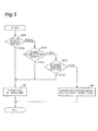
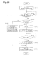
- Fig. 3 is a view showing the procedure when changing the SOC of the capacitor 19 according to the driving level of operating elements (rotary mechanism 2 (electric motor 21 for rotation), the boom 4, the arm 5, and the lifting magnet 6) in the hybrid type construction machine of the first example.
- This process is a process executed by the controller 50.
- the controller 50 starts the process shown in Fig. 3 during an operation of a hybrid type construction machine.
- the controller 50 determines whether or not the oil pressure of pressure oil detected by the sensor 14A is equal to or greater than the threshold value (step S1A). Since pressure oil from the main pump 14 is needed when driving an operating element of the hydraulic system, driving of the motor generator 12 which assists the engine 11 may be needed. Accordingly, a possibility of driving of the motor generator 12 is detected by detecting driving of the operating element of the hydraulic system.
- the controller 50 increases the state of charge (SOC) to 85% when it is determined that the oil pressure is equal to or greater than the threshold value (step S2). This is to increase the state of charge (SOC) according to driving of any of the operating elements of the hydraulic system in preparation for a case where the motor generator 12 performs electric (assistant) operation.
- step S1B the controller 50 determines whether or not driving of the lifting magnet 6 has been detected.
- driving the lifting magnet 6 it is necessary to supply electric power through the DC bus 40. Since it is necessary to increase the state of charge (SOC) in order to do so, it is determined whether or not driving of the lifting magnet 6 has been detected.
- SOC state of charge
- the controller 50 increases the state of charge (SOC) to 85% when driving of the lifting magnet 6 has been detected (step S2). This is to increase the state of charge (SOC) in preparation for supplying electric power to the lifting magnet 6.
- step SIC determines whether or not driving of the electric motor 21 for rotation has been detected.
- driving the electric motor 21 for rotation it is necessary to supply electric power through the DC bus 40. Since it is necessary to increase the state of charge (SOC) in order to do so, it is determined whether or not driving of the electric motor 21 for rotation has been detected.
- SOC state of charge
- the controller 50 increases the state of charge (SOC) to 85% when driving of the electric motor 21 for rotation has been detected (step S2). This is to increase the state of charge (SOC) in preparation for supplying electric power to the electric motor 21 for rotation.
- the controller 50 holds the state of charge (SOC) to 70%, (step S3). This is to increase the life of the capacitor 19 by holding the capacitor voltage in a low state because none of the operating elements (the operating element of the hydraulic system, the lifting magnet 6, and the electric motor 21 for rotation) is not driven.
- step S3 the controller 50 makes the motor generator 12 perform electric (assistant) operation so that the state of charge (SOC) is reduced to 70%.
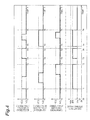
- Fig. 4 is a view showing a chart when changing the SOC of the capacitor 19 in the hybrid type construction machine of the first example.
- the state of charge (SOC) is held to 70% (low state) by the controller 50.
- step S2A If driving of an operating element of the hydraulic system is detected at time T1 (equivalent to YES in step S1A), the controller 50 increases the state of charge (SOC) to 85% (high state) (equivalent to step S2).
- SOC state of charge
- step S2 the state of charge (SOC) is increased to 85% (high state) (equivalent to step S2).
- step S3 if driving of the electric motor 21 for rotation ends at time T2 (equivalent to NO in step S1C), electric (assistant) operation of the motor generator 12 is performed by the inverter 18a so that electric energy from the capacitor 19 is converted into mechanical energy by the motor generator 12 and is then transmitted to the engine 11 by the controller 50. Also in this case, the driving torque of the engine 11 is increased by electric (assistant) operation of the motor generator 12. In this way, the state of charge (SOC) is increased to 70% (low state) (equivalent to step S3).
- SOC state of charge
- step S2 If driving of an operating element of the hydraulic system is detected again at time T3 (equivalent to YES in step S1A), the controller 50 increases the state of charge (SOC) to 85% (high state) (equivalent to step S2).
- SOC state of charge
- the controller 50 reduces the state of charge (SOC) to 70% (low state) (equivalent to step S3).
- step S2 the lifting magnet 6 is driven (equivalent to YES in step S1B), and the controller 50 increases the state of charge (SOC) to 85% (high state) (equivalent to step S2).
- step S3 the controller 50 reduces the state of charge (SOC) to 70% (low state) (equivalent to step S3). As described above, the operation shown in Fig. 4 is completed.
- the controller 50 sets the capacitor voltage to be low.
- the capacitor voltage is set to be low.
- the threshold value of SOC is to secure the sufficient state of charge when the next operation of the hybrid type construction machine is started and to secure a sufficient free space for charging regenerative power.
- the threshold value of SOC used for determination is not limited to 80% but may be suitably set according to the specifications and the like of an actual system.
- the state of charge (SOC) of the capacitor 19 is set to 70% when reducing the state of charge (SOC).
- SOC state of charge
- the state of charge (SOC) when set to be low is not limited to 70% but may be higher or lower than 70% as long as the responsiveness which does not cause a problem in the work can be secured when driving at least one of the operating element of the hydraulic system, the lifting magnet 6, and the electric motor 21 for rotation.
- hybrid type working machine of the present example is applied to a hybrid type construction machine including the motor generator 12 and the electric motor 21 for rotation for assisting the engine 11.
- elements which are electrically driven by hybridization are not limited to these, but the hybrid type working machine of the present example may be similarly applied to a hybrid type construction machine in which the hydraulic motors 1A and 1B, the boom cylinder 7, the arm cylinder 8, or the bucket cylinder 9 is electrically driven.
- a hybrid type construction machine of a second example is different from that of the first example in that the state of charge (SOC) of the capacitor 19 is set according to the number of revolutions of the engine 11. For this reason, an electrical signal indicating the number of revolutions of the engine 11 is input to the controller 50.
- SOC state of charge
- the controller 50 monitors the number of revolutions of the engine transmitted from a control device (for example, an ECU (Electronic Control Unit)) of the engine 11.
- a control device for example, an ECU (Electronic Control Unit) of the engine 11.
- the threshold value used for determination may be set to 1200 rpm.
- the number of revolutions of the engine 11 is changed by a volume switch provided together with the operating device 26 in the cabin 10.
- a volume switch provided together with the operating device 26 in the cabin 10.
- the driver sets the volume switch to a desired rated value (for example, 1800 rpm) during working and sets it to an idling state (1000 rpm) when not working.
- the hybrid type construction machine of the second example determines whether or not work is going on by monitoring the number of revolutions of the engine.
- the state of charge (SOC) of the capacitor 19 immediately after the start of operation (before operation) is set to 70%.
- the state of charge (SOC) is increased to 85%.
- the state of charge (SOC) is reduced to 70%.
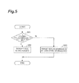
- Fig. 5 is a view showing the procedure when changing the SOC of the capacitor 19 according to the number of revolutions of the engine (driving level of the engine 11) in the hybrid type construction machine of the second example. This process is a process executed by the controller 50.
- the controller 50 starts the process shown in Fig. 5 during an operation of a hybrid type construction machine.
- the controller 50 determines whether or not the number of revolutions of the engine is equal to or greater than a threshold value (step S21). If the number of revolutions of the engine is increased, it is thought that work is going on. Accordingly, whether or not driving of an operating element of the hydraulic system, the lifting magnet 6, or the electric motor 21 for rotation is being performed is detected by monitoring the number of revolutions of the engine.
- the threshold value used for determination can be set to 1200 rpm, for example.
- the controller 50 increases the state of charge (SOC) to 85% when it is determined that the number of revolutions of the engine is equal to or greater than the threshold value (step S22). This is to increase the state of charge (SOC) according to driving of the operating element of the hydraulic system, the lifting magnet 6, or the electric motor 21 for rotation in preparation for a case where the motor generator 12 performs electric (assistant) operation.
- the controller 50 holds the state of charge (SOC) to 70%, (step S23). This is to increase the life of the capacitor 19 by holding the capacitor voltage in a low state because none of the operating elements (the operating element of the hydraulic system, the lifting magnet 6, and the electric motor 21 for rotation) is driven (non-working state).
- step S21 to S23 the process in steps S21 to S23 described above is repeatedly executed.
- the controller 50 makes the motor generator 12 perform electric (assistant) operation so that the state of charge (SOC) is reduced to 70%.
- Fig. 6 is a view showing a chart when changing the SOC of the capacitor 19 in the hybrid type constriction machine of the second example.
- the controller 50 sets the state of charge (SOC) to 70% (low state) (equivalent to step S23).
- step S21 when the number of revolutions of the engine becomes equal to or greater than the threshold value (1200 rpm) at time T22 (equivalent to YES in step S21), the controller 50 increases the state of charge (SOC) to 85% (high state) (equivalent to step S22).
- SOC state of charge
- the controller 50 sets the state of charge (SOC) to 70% (low state) (equivalent to step S23).
- step S21 when the number of revolutions of the engine becomes equal to or greater than the threshold value (1200 rpm) at time T24 (equivalent to YES in step S21), the controller 50 increases the state of charge (SOC) to 85% (high state) (equivalent to step S22).
- SOC state of charge
- the controller 50 sets the capacitor voltage to be low.
- the capacitor voltage is set to be low.
- a hybrid type construction machine of a third example is different from that of the first example in that the state of charge (SOC) of the capacitor 19 is set according to whether or not the levers 26A and 26B and the pedal 26C (hereinafter, simply referred to as "lever 26A and the like" in the third example) have been operated. For this reason, an electrical signal indicating whether or not the lever 26A and the like have been operated, which is transmitted from the pressure sensor 29, is input to the controller 50.
- SOC state of charge
- the hybrid type construction machine of the third example determines whether or not work is going on by determining whether or not the lever 26A and the like have been operated.
- the state of charge (SOC) of the capacitor 19 immediately after the start of operation (before operation) is set to 70%.
- the driving level of the engine 11 or the operating element the rotary mechanism 2 (electric motor 21 for rotation), the bucket 4, the arm 5, and the lifting magnet 6) is high and the state of charge (SOC) is increased to 85%.
- Fig. 7 is a view showing the procedure when changing the SOC of the capacitor 19 according to whether or not the lever 26A and the like have been operated (according to the driving level of an operating element according to the amount of operation input to the operating device 26) in the hybrid type construction machine of the third example. This process is executed by the controller 50.
- the controller 50 starts the process shown in Fig. 7 during an operation of a hybrid type construction machine.
- the controller 50 determines whether or not the lever 26A and the like have been operated (step S31). This is to detect driving of the operating element of the hydraulic system, the lifting magnet 6, or the electric motor 21 for rotation since work is going on when the lever 26A and the like have been operated.
- the controller 50 increases the state of charge (SOC) to 85% when it is determined that there is an operation of the lever 26A and the like (step S32). This is to increase the state of charge (SOC) according to driving of the operating element of the hydraulic system, the lifting magnet 6, or the electric motor 21 for rotation in preparation for a case where the motor generator 12 performs electric (assistant) operation.
- step S33 the state of charge (SOC) is held to 70% (step S33). This is to increase the life of the capacitor 19 by holding the capacitor voltage in a low state because none of the operating elements (the operating element of the hydraulic system, the lifting magnet 6, and the electric motor 21 for rotation) is driven (non-working state).
- step S33 the process in steps S31 to S33 described above is repeatedly executed.
- the controller 50 makes the motor generator 12 perform electric (assistant) operation so that the state of charge (SOC) is reduced to 70%.
- Fig. 8 is a view showing a chart when changing the SOC of the capacitor 19 in the hybrid type construction machine of the third example.
- step S31 If it is determined that there is an operation of the lever 26A and the like at time T31 (equivalent to step S31), the controller 50 increases the state of charge (SOC) to 85% (high state) (equivalent to step S32).
- SOC state of charge
- the controller 50 sets the state of charge (SOC) to 70% (low state) (equivalent to step S33).
- the controller 50 increases the state of charge (SOC) to 85% (high state) (equivalent to step S32).
- the controller 50 sets the state of charge (SOC) to 70% (low state) (equivalent to step S33).
- the controller 50 sets the capacitor voltage to be low.
- the capacitor voltage is set to be low.
- a hybrid type construction machine of a fourth example is different from that of the first example in that the state of charge (SOC) of the capacitor 19 is set according to whether or not a gate lock lever has been operated. For this reason, an electrical signal indicating an opening and closing state of a gate lock lever is input to the controller 50.
- SOC state of charge
- Figs. 9A and 9B are views showing a driver's seat and the periphery of the hybrid type construction machine of the fourth example.
- Fig. 9A is a perspective view
- Fig. 9B is a side view showing a console located at the left side of the driver's seat.
- a gate lock operating section 60 is a gate locking device for switching between a state where a construction machine can be used (operable state) and a state where the construction machine cannot be used (inoperable state).
- the gate lock operating section 60 is provided to prevent a malfunction of the construction machine.
- the gate lock operating section 60 will be described with reference to Figs. 9A and 9B .
- Consoles 10B are provided at both sides of a driver's seat 10A disposed in the cabin 10, and a pair of operating levers 26A is provided in the pair of consoles 10B. From the left side with respect to the cabin front direction, the operator can get on and off the driver's seat 10A.
- the gate lock operating section 60 is provided in the left console 10B.
- the gate lock operating section 60 provided in the left console 10B includes a gate lock lever 60A, a gate 60B, and a limit switch 60C.
- the gate lock operating section 60 is disposed at a side of the driver's seat provided in the cabin of the upper revolving body 3, and is an operating section for opening and closing operation of the gate 60B provided in a portion for getting on/off a driver's seat.
- the gate 60B and the gate lock lever 60A are connected to each other by a wire.
- the gate 60B is closed (state indicated by a solid line) if the gate lock lever 60A is pulled up, and the gate 60B is opened if the gate lock lever 60A is pulled down (state indicated by a broken line).
- the driver cannot get down from the driver's seat when the gate is closed and can get down when the gate is opened.
- the limit switch 60C is a sensor for detecting the operation of the gate lock lever 60A.
- the limit switch 60C is turned on when the gate lock lever 60A is pulled up and is turned off when the gate lock lever 60A is pulled down.
- This limit switch 60C is connected to a shutoff valve, which is provided in the pilot line 25 which transmits pilot pressure from the pilot pump 15 to the operating device 26, so that switching between a connection state and a cutoff state is performed according to an electrical signal transmitted from the limit switch 60C.
- the limit switch 60C is set to a connection state so that pilot pressure is transmitted to the operating device 26.
- the limit switch 60C is set to a cutoff state so that transmission of pilot pressure to the operating device 26 is cut off. Switching control of the shutoff valve is performed by the gate lock operating section 60.
- a relay of the shutoff valve is turned on. If the limit switch 60C is turned off, the relay is turned off. Thus, the shutoff valve is switched by the limit switch 60C. In addition, a signal indicating ON/OFF of the limit switch 60C is also input to a controller 30.
- the relay In a state where the gate lock lever 60A is pulled up and the gate 60B is closed, the relay is turned on to set the shutoff valve to a connection state. Then, the construction machine becomes in a usable state (operable state). On the other hand, in a state where the gate lock lever 60A is pulled down and the gate 60B is opened, the relay is turned off to set the shutoff valve to a cutoff state. Then, the construction machine enters an unusable state (inoperable state). This is to prevent a malfunction.
- the controller 50 monitors whether or not there is an operation of the gate lock lever 60A transmitted from the gate lock operating section 60. The controller 50 determines whether or not work is going on by determining whether or not the gate lock lever 60A has been operated.
- the state of charge (SOC) of the capacitor 19 immediately after the start of operation (before operation) is set to 70%.
- the state of charge (SOC) is increases to 85%.
- the state of charge (SOC) is reduced to 70%.
- the state of charge (SOC) of the capacitor 19 is increased to 85%.
- Fig. 10 is a view showing the procedure when changing the SOC of the capacitor 19 according to whether or not the gate lock lever 60A has been operated in the hybrid type construction machine of the fourth example.
- the driving level of the engine 11 or the operating element (the rotary mechanism 2 (electric motor 21 for rotation), the bucket 4, the arm 5, and the lifting magnet 6) is determined according to whether or not the gate lock lever 60 has been operated (according to the operation state), and the SOC is changed by making the motor generator 12 perform electric (assistant) operation.
- This process is a process executed by the controller 50.
- the case where it is determined that the gate lock lever 60A has been pulled up is expressed as "operated”
- the case where it is determined that the gate lock lever 60A has been pulled down is expressed as "not operated”.
- the controller 50 starts the process shown in Fig. 10 during an operation of a hybrid type construction machine.
- the controller 50 determines whether or not the gate lock lever 60A has been operated (step S41). This is to detect driving of the operating element of the hydraulic system, the lifting magnet 6, or the electric motor 21 for rotation since work is going on when the gate lock lever 60A has been operated.
- the controller 50 increases the state of charge (SOC) to 85% when it is determined that the gate lock lever 60A has been operated (step S42). This is to increase the state of charge (SOC) according to driving of the operating element of the hydraulic system, the lifting magnet 6, or the electric motor 21 for rotation in preparation for a case where the motor generator 12 performs electric (assistant) operation.
- step S43 the state of charge (SOC) is held to 70% (step S43). This is to increase the life of the capacitor 19 by holding the capacitor voltage in a low state because none of the operating elements (the operating element of the hydraulic system, the lifting magnet 6, and the electric motor 21 for rotation) is driven (state where working is prohibited).
- step S43 the controller 50 makes the motor generator 12 perform electric (assistant) operation so that the state of charge (SOC) is reduced to 70%.
- Fig. 11 is a view showing a chart when changing the SOC of the capacitor 19 in the hybrid type construction machine of the fourth example.
- the state of charge (SOC) is held to 70% (low state) by the controller 50.
- step S41 If it is determined that the gate lock lever 60A has been operated at time T41 (equivalent to step S41), the controlled 50 increases the state of charge (SOC) to 85% (high state) (equivalent to step S42).
- SOC state of charge
- the controller 50 sets the state of charge (SOC) to 70% (low state) (equivalent to step S43).
- step S41 the controller 50 increases the state of charge (SOC) to 85% (high state) (equivalent to step S42).
- the controller 50 sets the state of charge (SOC) to 70% (low state) (equivalent to step S43).
- the controller 50 sets the capacitor voltage to be low.
- the capacitor voltage is set to be low.
- a hybrid type construction machine of a fifth example is different from that of the first example in that the state of charge (SOC) of the capacitor 19 is set according to the operation position of an ignition switch. For this reason, an electrical signal indicating whether or not the lever 26A and the like have been operated, which is transmitted from the ignition switch, is input to the controller 50.
- the ignition switch is provided at a side of the driver's seat 10A shown in Fig. 9 .
- the hybrid type construction machine of the fifth example determines that the engine 11 is in the operation state when the operation position of the ignition switch reaches a START (mode for driving a starter) position from an OFF position through an ACC (accessory mode) position and is then set to the ON position. In addition, when the ignition switch is operated to move from the ON position to the ACC position or the OFF position, it is determined that the engine 11 has stopped.
- START mode for driving a starter
- ACC accessory mode
- the state of charge (SOC) of the capacitor 19 immediately after the start of operation (before operation) is set to 70%.
- the state of charge (SOC) is increased to 85%.
- the state of charge (SOC) is reduced to 70%.
- the state of charge (SOC) of the capacitor 19 is increased to 85%.
- Fig 12 is a view showing the procedure when changing the SOC of the capacitor 19 according to the operation position of the ignition switch in the hybrid type construction machine of the fifth example.
- the driving level of the engine 11 or the operating element (the rotary mechanism 2 (electric motor 21 for rotation), the bucket 4, the arm 5, and the lifting magnet 6) is determined according to the operation position of the ignition switch, and the SOC is changed by making the motor generator 12 perform electric (assistant) operation.
- this process is a process executed by the controller 50.
- the controller 50 starts the process shown in Fig. 12 during an operation of a hybrid type construction machine.
- the controller 50 determines whether or not the engine 11 has started up on the basis of a change in the operation position of the ignition switch (step S51). This is to detect driving of the operating element of the hydraulic system, the lifting magnet 6, or the electric motor 21 for rotation since work is going on when the engine 11 has started.
- the controller 50 increases the state of charge (SOC) to 85% when it is determined that the engine 11 has started on the basis of a change in the operation position of the ignition switch (step S52). This is to increase the state of charge (SOC) according to driving of the operating element of the hydraulic system, the lifting magnet 6, or the electric motor 21 for rotation in preparation for a case where the motor generator 12 performs electric (assistant) operation.
- the controller 50 holds the state of charge (SOC) to 70% when it is determined that the engine 11 has stopped on the basis of a change in the operation position of the ignition switch (step S53). This is to increase the life of the capacitor 19 by holding the capacitor voltage in a low state by the stopping of the engine 11 because none of the operating elements (the operating element of the hydraulic system, the lifting magnet 6, and the electric motor 21 for rotation) is driven (non-working state).
- step S53 the controller 50 makes the motor generator 12 perform electric (assistant) operation so that the state of charge (SOC) is reduced to 70%.
- Fig. 13 is a view showing a chart when changing the SOC of the capacitor 19 in the hybrid type construction machine of the fifth example.
- the state of charge (SOC) is held to 70% (low state) by the controller 50.
- step S51 If it is determined that the engine 11 has started on the basis of a change in the operation position of the ignition switch at time T51 (equivalent to YES in step S51), the controller 50 increases the state of charge (SOC) to 85% (high state) (equivalent to step S52).
- SOC state of charge
- the controller 50 sets the state of charge (SOC) to 70% (low state) (equivalent to step S53).
- the controller 50 increases the state of charge (SOC) to 85% (high state) (equivalent to step S52).
- the controller 50 sets the state of charge (SOC) to 70% (low state) (equivalent to step S53).
- the controller 50 sets the capacitor voltage to be low.
- the capacitor voltage is set to be low.
- the hybrid type working machine may be a working machine other than a construction machine.
- it may be a hybrid type transportation and loading and unloading machine (a crane or a forklift).
- a power source for lifting components, goods, and the like up and down performs a power operation (at the time of rolling up) and a regenerative operation (at the time of rolling down) according to the rolling up or down of a wire, it can be executed as a hybrid type working machine similar to the hybrid type construction machine described above.
- a power source for lifting a fork up and down performs power operation (at the time of rolling up) and regenerative operation according to an up-and-down operation, it can be executed as a hybrid type working machine similar to the hybrid type construction machine described above.
- the state of charge of a battery can be reduced according to the working state or the operation state.
- Fig. 14 is a perspective view showing the appearance of a hybrid type construction machine 1001 as an example of a working machine related to the present invention.
- the hybrid type construction machine 1001 is a so-called lifting magnet vehicle and includes a traveling mechanism 1002 having an endless track and a revolving body 1004 which is rotatably mounted on the traveling mechanism 1002 with a rotary mechanism 1003 interposed therebetween.
- a boom 1005, an arm 1006 which is link-connected to the tip of the boom 1005, and a lifting magnet 1007 which is link-connected to the tip of the arm 1006 are fixed to the revolving body 1004.
- the lifting magnet 1007 is a facility for adsorbing and capturing a hoisted load G, such as steel, by the magnetic force.
- the boom 1005, the arm 1006, and the lifting magnet 1007 are hydraulically driven by a boom cylinder 1008, an arm cylinder 1009, and a bucket cylinder 1010, respectively.
- an operator's cabin 1004a in which an operator who performs a position operation or an excitation operation and a release operation on the lifting magnet 1007 is located, or a power source, which is called an engine (internal combustion engine) 1011 for generating oil pressure, is provided in the revolving body 1004.
- the engine 1011 is a diesel engine, for example.
- the hybrid type construction machine 1001 includes a servo control unit 1060.
- the servo control unit 1060 controls charging and discharging of an AC motor for driving the operating elements, such as the rotary mechanism 1003 and the lifting magnet 1007, a motor generator for assisting the engine 1011, and a battery.
- the servo control unit 1060 includes an inverter unit for driving an AC motor or a motor generator by converting DC power into AC power, a plurality of driver units called step-up and step-down converter units which control charging and discharging of a battery, and a control unit for controlling the plurality of driver units.
- Fig. 15 is a block diagram showing the internal configuration of an electrical system or a hydraulic system of the hybrid type construction machine 1001 of the present example. Moreover, in Fig. 15 , a system which transmits power mechanically, a hydraulic system, a control system, and an electrical system are indicated by a double line, a thick solid line, a broken line, and a thin solid line, respectively. In addition, Fig. 16 is a view showing the internal configuration of a storage section 1120 in Fig. 15 .
- the hybrid type construction machine 1001 includes a motor generator 1012 and a decelerator 1013, and both rotary shafts of the engine 1011 and the motor generator 1012 are connected to each other by being connected to an input shaft of the decelerator 1013.
- the motor generator 1012 drives the engine 1011 as an operating element to assist a driving force of the engine 1011, so that the driving force of the motor generator 1012 is transmitted to the main pump 1014 through the output shaft of the decelerator 1013.
- the driving force of the engine 1011 is transmitted to the motor generator 1012 through the decelerator 1013 so that the motor generator 1012 performs power generation.
- the motor generator 1012 may be formed by an IPM (Interior Permanent Magnetic) motor in which a magnet is embedded in a rotor. Switching between driving and power generation of the motor generator 1012 is performed according to the load of the engine 1011 or the like by a controller 1030 which performs driving control of the electrical system in the hybrid type construction machine 1001.
- IPM Interior Permanent Magnetic
- a main pump 1014 and a pilot pump 1015 are connected to the output shaft of the decelerator 1013, and a control valve 1017 is connected to the main pump 1014 through a high-pressure hydraulic system 1016.
- the control valve 1017 is a device which controls the hydraulic system in the hybrid type construction machine 1001. Not only hydraulic motors 1002a and 1002b for driving the traveling mechanism 1002 shown in Fig. 14 but also the boom cylinder 1008, the arm cylinder 1009, and the bucket cylinder 1010 are connected to the control valve 1017 through a high-pressure hydraulic line, and the control valve 1017 controls the oil pressure supplied to those described above according to a driver's operation input.
- the inverter circuit 1018A is a third inverter circuit in the present example.
- the storage section 1120 is connected to an input end of the inverter circuit 1018A.
- the storage section 1120 includes a DC bus 1110 which forms a DC wiring line, a step-up and step-down converter (DC voltage converter) 1100, and a battery 1019. That is, an input end of the inverter circuit 1018A is connected to an input end of the step-up and step-down converter 1100 through the DC bus 1110.
- the battery 1019 is connected to an output end of the step-up and step-down converter 1100.
- the battery 1019 is formed by a capacitor type battery, for example.
- the inverter circuit 1018A performs operation control of the motor generator 1012 according to a command from the controller 1030. That is, when the inverter circuit 1018A makes the motor generator 1012 perform power operation, required electric power is supplied from the battery 1019 and the step-up and step-down converter 1100 to the motor generator 1012 through the DC bus 1110. In addition, when the inverter circuit 1018A makes the motor generator 1012 perform regenerative operation, electric power generated by the motor generator 1012 is charged to the battery 1019 through the DC bus 1110 and the step-up and step-down converter 1100.
- step-up operation and step-down operation of the step-up and step-down converter 1100 is performed on the basis of the DC bus voltage value, the battery voltage value, and the battery current value by the controller 1030. Accordingly, the DC bus 1110 can be maintained in a state being electrically charged as a fixed voltage value set in advance.
- the lifting magnet 1007 is connected to the DC bus 1110 of the storage section 1120 through an inverter circuit 1020B.
- the lifting magnet 1007 includes an electromagnet, which generates a magnetic force for adsorbing a metal material magnetically, and receives electric power from the DC bus 1110 through the inverter circuit 1020B.
- the inverter circuit 1020B supplies electric power requested to the lifting magnet 1007 from the DC bus 1110 according to a command from the controller 1030 when turning on an electromagnet. In addition, when turning off the electromagnet, the inverter circuit 1020B supplies the regenerated electric power to the DC bus 1110.
- an inverter circuit 1020A is connected to the storage section 1120.
- An electric motor 1021 for rotation (AC motor) as an electric motor for operation (first electric motor) is connected to one end of the inverter circuit 1020A, and the other end of the inverter circuit 1020A is connected to the DC bus 1110 of the storage section 1120.
- the electric motor 1021 for rotation is a power source of the rotary mechanism 1003 which rotates the revolving body 1004.
- a resolver 1022, a mechanical brake 1023, and a rotation speed reduction mechanism 1024 are connected to a rotary shaft 1021A of the electric motor 1021 for rotation.
- the inverter circuit 1020A is a first inverter circuit in the present example.
- the electric motor 1021 for rotation When the electric motor 1021 for rotation performs power operation, torque of the rotational driving force of the electric motor 1021 for rotation is amplified by the rotation speed reduction mechanism 1024, and the revolving body 1004 performs rotational operation by acceleration and deceleration control. Moreover, by inertial rotation of the revolving body 1004, the number of revolutions in the rotation speed reduction mechanism 1024 is increased and is transmitted to the electric motor 1021 for rotation so that regenerative power is generated.
- the electric motor 1021 for rotation is AC-driven by the inverter circuit 1020A using a PWM (Pulse Width Modulation) control signal.
- PWM Pulse Width Modulation
- the electric motor 1021 for rotation for example, a magnet embedded type IPM motor is suitable.
- the resolver 1022 is a sensor which detects the rotation position and the rotation angle of the rotary shaft 1021A of the electric motor 1021 for rotation.
- the resolver 1022 is mechanically connected with the electric motor 1021 for rotation in order to detect the rotation angle and the rotation direction of the rotary shaft 1021A.
- the mechanical brake 1023 is a braking device which generates a mechanical braking force and stops the rotary shaft 1021A of the electric motor 1021 for rotation mechanically according to a command from the controller 1030.
- the rotation speed reduction mechanism 1024 is a decelerator which reduces the rotation speed of the rotary shaft 1021A of the electric motor 1021 for rotation and mechanically transmits it to the rotary mechanism 1003.
- the motor generator 1012, the electric motor 1021 for rotation, and the lifting magnet 1007 are connected to the DC bus 1110 through the inverter circuits 1018A, 1020A, and 10208, respectively. Accordingly, electric power generated by the motor generator 1012 may be directly supplied to the lifting magnet 1007 or the electric motor 1021 for rotation, electric power regenerated by the lifting magnet 1007 may be supplied to the motor generator 1012 or the electric motor 1021 for rotation, and electric power regenerated by the electric motor 1021 for rotation may be supplied to the motor generator 1012 or the lifting magnet 1007.
- the hybrid type construction machine 1001 of the present example includes a coolant circulation system 1070 for cooling the step-up and step-down converter 1100 and the inverter circuits 1018A, 1020A, and 1020B separately from a coolant circulation system for the engine 1011.
- the coolant circulation system 1070 includes a pump 1072 for circulating the coolant, which is supplied to the step-up and step-down converter 1100, the inverter circuits 1018A, 1020A, and 1020B, and the like, and a pump motor (electric motor for cooling) 1071 which drives the pump 1072.
- the pump motor 1071 is also a second electric motor in the present example.
- the pump motor 1071 is connected to the storage section 1120 through an inverter circuit 1020C.
- the inverter circuit 1020C is a second inverter circuit in the present example.
- the inverter circuit 1020C supplies electric power, which is requested to the pump motor 1071 when cooling the step-up and step-down converter 1100, according to a command from the controller 1030.
- the coolant circulation system 1070 of the present example cools the step-up and step-down converter 1100, the inverter circuits 1018A, 1020A, and 1020B, and the controller 1030. In addition, the coolant circulation system 1070 cools the motor generator 1012, the decelerator 1013, and the electric motor 1021 for rotation.
- An operating device 1026 is connected to the pilot pump 1015 through a pilot line 1025.
- the operating device 1026 is an operating device for operating the electric motor 1021 for rotation, the traveling mechanism 1002, the boom 1005, the arm 1006, and the lifting magnet 1007, and is operated by an operator.
- the control valve 1017 is connected to the operating device 1026 through a hydraulic line 1027, and a pressure sensor 1029 is connected to the operating device 1026 through a hydraulic line 1028.
- the operating device 1026 converts the oil pressure (oil pressure on the primary side), which is supplied through the pilot line 1025, into the oil pressure (oil pressure on the secondary side) according to the amount of operation of the operator and outputs it.
- the oil pressure on the secondary side output from the operating device 1026 is supplied to the control valve 1017 through the hydraulic line 1027 and is also detected by a pressure sensor 1029.
- the electric motor 1021 for rotation as an electric motor for operation is mentioned.
- the traveling mechanism 1002 may be electrically driven as an electric motor for operation.
- a lifting device may be electrically driven as an electric motor for operation.
- the pressure sensor 1029 detects the amount of operation as a change of oil pressure in the hydraulic line 1028.
- the pressure sensor 1029 outputs an electrical signal indicating the oil pressure in the hydraulic line 1028.
- the electrical signal is input to the controller 1030 and is used for driving control of the electric motor 1021 for rotation.
- the controller 1030 forms a control unit in the present example.
- the controller 1030 is formed by an arithmetic processing unit including a CPU and an internal memory, and is realized when the CPU executes a program for driving control stored in the internal memory.
- a power source of the controller 1030 is a separate battery (for example, a 24 V in-vehicle battery) from the battery 1019.
- the controller 1030 converts a signal, which indicates the amount of operation for rotating the rotary mechanism 1003, among signals input from the pressure sensor 1029 into a speed command and performs driving control of the electric motor 1021 for rotation.
- controller 1030 controls charging and discharging of the battery 1019 by performing operation control (switching between assistant operation and power generation operation) of the motor generator 1012, driving control (switching between excitation and degaussing) of the lifting magnet 1007, and driving control of the step-up and step-down converter 1100.
- the controller 1030 of the present example has a discharge mode for discharging electric power which is stored in the battery 1019 when executing the maintenance of the hybrid type construction machine 1001 and the like.
- the controller 1030 stops all of the inverter circuits 1018A, 1020A, and 1020B while making the pump motor 1071 consume electric power by driving the inverter circuit 1020C, so that the battery 1019 is discharged.
- the start of the discharge mode is determined by an operator through an operation panel in the operator's cabin 1004a (see Fig. 14 ).
- the step-up and step-down converter 1100 uses a step-up and step-down type switching control method, and includes the reactor 1101, transistors 1100B and 1100C, and a smoothing capacitor 1100d.
- the transistor 1100B is a step-up switching element
- the transistor 1100C is a step-down switching element.
- the transistors 1100B and 1100C are formed by IGBT (Insulated Gate Bipolar transistor) and are connected in series to each other.
- a collector of the transistor 1100B and an emitter of the transistor 1100C are connected to each other, an emitter of the transistor 1100B is connected to a negative terminal of the battery 1019 and a negative side wiring line of the DC bus 1110, and a collector of the transistor 1100C is connected to a positive side wiring line of the DC bus 1110.
- one end of the reactor 1101 is connected to the collector of the transistor 1100B and the emitter of the transistor 1100C, the other end is connected to a positive side terminal of the battery 1019 through a switch 1100E.
- a PWM voltage from the controller 1030 is applied to gates of the transistors 1100B and 1100C.
- a connection state of the switch 1100E is controlled by a command from the controller 1030.
- a diode 1100b which is a rectifying element is connected in the reverse direction and in parallel between the collector and the emitter of the transistor 1100B.
- a diode 1100c is connected in the reverse direction and in parallel between the collector and the emitter of the transistor 1100C.
- the smoothing capacitor 1100d is connected between the collector of the transistor 1100C and the emitter of the transistor 1100B and smoothes the output voltage from the step-up and step-down converter 1100.
- a voltage sensor 1100F for detecting the voltage between both ends of the battery 1019 is provided. A result of voltage detection by the voltage sensor 1100F is supplied to the controller 1030.
- step-up and step-down converter 1100 when supplying DC power from the battery 1019 to the DC bus 1110, a PWM voltage is applied to the gate of the transistor 1100B according to a command from the controller 1030, the induced electromotive force generated in the reactor 1101 according to ON/OFF of the transistor 1100B is transmitted through the diode 1100c, and the electric power is smoothed by the capacitor 1100d.
- a PWM voltage is applied to the gate of the transistor 1100C according to a command from the controller 1030 and a current output from the transistor 1100C is smoothed by the reactor 1101.
- the controller 1030 controls neither of the transistors 1100B and 1100C, and electric power stored in the battery 1019 is transmitted to the DC bus 1110 through the diode 1100c.
- Fig. 17 is a block diagram for explaining the coolant circulation system 1070.
- the coolant circulation system 1070 includes the pump 1072 driven by the pump motor 1071, a radiator 1073, and the servo control unit 1060.
- the coolant circulated by the pump 1072 is heat-radiated by the radiator 1073 and is then sent to the servo control unit 1060.
- the servo control unit 1060 has a pipe for cooling the step-up and step-down converter 1100, the inverter circuits 1018A, 1020A, and 1020B, and the controller 1030, and the coolant circulates through the inside of the pipe.
- the coolant having passed through the pipe of the servo control unit 1060 cools the electric motor 1021 for rotation, the motor generator 1012, and the decelerator 1013 in this order and then returns from the pump 1072 to the radiator 1073.
- a temperature sensor 1077 for detecting the temperature of the coolant at the inlet of the servo control unit 1060.
- a display device which displays the detected temperature. In this case, if the radiator clogs 1073 to lower the cooling capability, outputs of the electric motor 1021 for rotation and the motor generator 1012 (or one of these) can be restricted on the basis of the temperature detection value. As a result, since continuous operation becomes possible, continuous working becomes possible without stopping the hybrid type construction machine 1001.
- Fig. 18 is a perspective view showing the appearance of the servo control unit 1060.
- the servo control unit 1060 has an approximately rectangular parallelepiped appearance and includes a control unit 1600, which has the controller 1030, a step-up and step-down converter unit 1066, and inverter units 1062 to 1065.
- the step-up and step-down converter unit 1066 has the step-up and step-down converter 1100, and the inverter units 1062 to 1065 have the inverter circuits 1018A, 1020A, and 1020B and other inverter circuits.
- Each of the step-up and step-down converter unit 1066 and the inverter units 1062 to 1065 has a metal container with a rectangular parallelepiped shape which is long in the depth direction.
- These units 1062 to 1066 are provided in a plate-shaped pedestal 1067, which is formed of metal and a top surface of which is opened, in a state located side by side in a direction perpendicular to their longitudinal directions and, each of the units 1062 to 1066 is fixed to the pedestal 1067 with a bolt.
- a control unit low plate 1061 as a top cover is provided so as to cover the upper surfaces of the units 1062 to 1066.
- the control unit 1600 is placed on the control unit low plate 1061.
- a heat sink 1068 for air cooling is fixed to the upper surface of the control unit 1600.
- the upper surface sides of the units 1062 to 1066 are sealed by the control unit low plate 1061.
- the control unit 1600 has a controller for controlling the step-up and step-down converter unit 1066 and the inverter units 1062 to 1065.
- the controller has an arithmetic processing unit including a CPU and an internal memory, and is realized when the CPU executes a program for driving control stored in the internal memory.
- a cooling pipe 1608 is provided in the control unit 1600.
- a cooling pipe 1066a is provided in the step-up and step-down converter unit 1066, and cooling pipes 1062a to 1065a are provided in the inverter units 1062 to 1065, respectively.
- Fig. 19 is a perspective view showing a state where the cooling pipes 1062a to 1066a are connected.
- the pipe 1090B is connected to one end of the cooling pipe 1608 of the control unit 1600, and the other end of the cooling pipe 1608 is connected to one end of the cooling pipe 1062a of the inverter unit 1062 through another pipe 1090E.
- the pipe 1090C is connected to one end of the cooling pipe 1066a of the step-up and step-down converter unit 1066, and the other end of the cooling pipe 1066a is connected to one end of the cooling pipe 1064a of the inverter unit 1064 through another pipe 1090F.
- the pipe 1090D is connected to one end of the cooling pipe 1065a of the inverter unit 1065, and the other end of the cooling pipe 1065a is connected to one end of the cooling pipe 1063a of the inverter unit 1063 through a pipe 1090G.
- pipes 1090J, 10901, and 1090H are connected to the other ends of the cooling pipes 1062a to 1064a of the inverter units 1062 to 1064, respectively.
- the pipes 1090J, 1090I, and 1090H are connected to one pipe 1090K.
- the pipe 1090K is provided to extend to other elements to be cooled, such as the electric motor 1021 for rotation.
- Fig. 20A is a planar sectional view of the control unit 1600
- Fig. 20B is a side sectional view taken along the line I-I in Fig. 20A
- Fig. 20C is a side sectional view taken along the line II-II in Fig. 20A
- Fig. 20D is a side sectional view taken along the line III-III in Fig. 20A
- Fig. 21A is a side sectional view taken along the line IV-IV in Fig. 20A
- Fig. 21B is a side view when viewing the control unit 1600 from the same direction as in Fig. 21A .
- the control unit 1600 has a housing 1601 which includes a housing container 1601a and a housing cover 1601b, and an electronic circuit and the like of a controller are housed in the housing 1601.
- the housing 1601 of the control unit 1600 has a rectangular parallelepiped appearance and is provided on the step-up and step-down converter unit 1066 and the inverter units 1062 to 1065 which are a plurality of driver units.
- the housing 1601 has an approximately rectangular parallelepiped inner space on the bottom surface which has an approximately rectangular planar shape. This inner space is blocked from the ambient air, and the housing 1601 of the control unit 1600 has a sealed structure.
- a direction in which the units 1062 to 1066 are arrayed is equal to the short side direction of the control unit 600, and this direction is equivalent to a vertical direction with respect to the plane in Fig. 20A .
- a direction perpendicular to the direction in which the plurality of units 1062 to 1066 are arrayed is equal to the longitudinal direction of the control unit 1600, and this direction is equivalent to a horizontal direction with respect to the plane in Fig. 20A .
- a card plate 1602 with a rectangular planar shape is provided on the bottom surface in the housing 1601.
- the card plate 1602 is disposed in a state where the longitudinal direction and the short side direction of the card plate 1602 match the longitudinal direction and the short side direction of the control unit 1600, respectively.
- An opening with an approximately rectangular planar shape is provided in the card plate 1602.
- a heat sink (thermally conductive plate) 1603 which has a planar shape, which is approximately the same shape as the opening, and also has an approximately rectangular parallelepiped appearance is provided on the bottom surface in the housing 1601.
- the heat sink 1603 is for cooling electronic components provided in the housing 1601 and is provided such that the cooling pipe 1608 is thermally coupled (for example, contacted) with the heat sink 1603.
- the heat sink 1603 is cooled by the coolant which circulates through the cooling pipe 1608.
- the coolant is water, for example.
- a control card 1604 which has an approximately rectangular planar shape is provided on the heat sink 1603.
- the control card 1604 is a substrate on which various electronic components are mounted and is disposed such that the back surface faces the heat sink 1603.
- a plurality of CPUs 1605a to 1605e is mounted as examples of electronic components.
- the plurality of CPUs 1605a to 1605e corresponds to the plurality of units 1062 to 1066 in a one-to-one manner and controls ON/OFF of a transistor included in an inverter circuit of a corresponding unit of the units 1062 to 1066.
- the plurality of CPUs 1605a to 1605e is thermally coupled with the heat sink 1603. That is, the heat sink 1603 is disposed between the plurality of CPUs 1605a to 1605e and the cooling pipe 1608.
- a plurality of fans 1606a is arrayed in the short side direction of the control unit 1600.
- the plurality of fans 1606a is provided corresponding to the CPUs 1605a to 1605e in order to eliminate the temperature gradient in the housing by churning the air, which is heated by the heat generated in the CPUs 1605a to 1605e, and generates the airflow which moves toward each of the CPUs 1605a to 1605e.
- a card plate 1613 with a rectangular planar shape is further provided together with the card plate 1602.
- a power card 1609 is provided on the card plate 1613.
- Two power supply ICs (power supply units) 1610 are provided on the power card 1609.
- a heat sink 1611 for air-cooling of the power supply IC is provided in each power supply IC 1610.
- a thermally conductive plate 1614 is provided so as to be in contact with the internal surface of the housing 1601, and the power supply IC 1610 and the heat sink 1611 are in contact with the surface of the thermally conductive plate 1614. Accordingly, it is possible to radiate a part of the heat generated in the power supply IC 1610.
- two fans 1606b are provided on the card plate 1613. These fans 1606b are provided in order to eliminate the temperature gradient in the housing by churning the air, which is heated by the heat generated in the power supply IC 1610, and generates the airflow which moves toward power supply IC 1610.
- I/O sections of electronic components mounted on the control card 1604 are connected to a connector 1607.
- command signals for operating the units 1062 to 1066, output signals from electronic components, and the like are input or output through the connector 1607.
- the connector 1607 is connected with, for example, a control unit (not shown) for controlling the servo control unit 1060, by a wire.
- the connector 1607 is provided in a recessed hollow portion on the side surface of the housing 1601, and the hollow portion is covered with a packing 1616.
- the packing 1616 is covered with a packing pressure member 1617 through a housing cover 1601b. Protection of the connector 1607 against water and dust is realized by the packing 1616.
- Figs. 22A to 24 are views showing a cooling structure.
- Fig. 22A is a plan view showing the heat sink 1603 and the cooling pipe 1608, and
- Fig. 22B is a side sectional view taken along the line V-V in Fig. 22A .
- Fig. 23 is a plan view showing the control card 1604 disposed to cover the heat sink 1603 and the cooling pipe 1608.
- Fig. 24 is a side sectional view showing a part of the section taken along the line VI-VI in Fig. 23 .
- the cooling pipe 1608 in the present example is formed in a hairpin pipe shape and is bonded and fixed to the back surface side of the heat sink 1603. More specifically, the cooling pipe 1608 is configured to include a plurality of pipe portions 1608a.
- the plurality of pipe portions 1608a extends in the short side direction of the heat sink 1603 and is provided in parallel at predetermined distances therebetween in the longitudinal direction of the heat sink 1603 crossing the short side direction.
- one ends and the other ends of the plurality of pipe portions 1608a are alternately connected in a U shape to the pipe portions 1608b, thereby forming a single pipe as a whole.
- the heat sink 1603 has a plurality of cooling regions 1603a to 1603e with rectangular shapes which extends in the short side direction of the heat sink 1603 and are located side by side in the longitudinal direction of the heat sink 1603.
- Each of the plurality of cooling regions 1603a to 1603e is thermally coupled with two adjacent pipe portions 1608a among the plurality of pipe portions 1608a.
- each of the plurality of cooling regions 1603a to 1603e is demarcated to include two pipe portions 1608a when viewed from above.
- the plurality of CPUs 1605a to 1605e is mounted on the back surface of the control card 1604 and a plurality of electrical components including an electric contact 1618 for generating an electrical signal to an electromagnetic valve or the like is disposed on the top surface, as described above.
- the plurality of CPUs 1605a to 1605e are connected by a pattern wire formed on the control card 1604 so that communications can be performed.
- These CPUs 1605a to 1605e are arrayed side by side in the longitudinal direction of the heat sink 1603 and are also arrayed on the cooling regions 1603a to 1603e of the heat sink 1603, respectively.
- the CPU 1605a is thermally coupled with the cooling region 1603a of the heat sink 1603 through a thermally conductive sheet 1612
- the CPU 1605b is thermally coupled with the cooling region 1603b through the thermally conductive sheet 1612 (see Fig. 24 ).
- the CPUs 1605c to 1605e are thermally coupled with the cooling regions 1603c-1603e through thermally conductive sheets, respectively. That is, in the present example, each of the plurality of CPUs 1605a to 1605e is thermally coupled with one cooling region.
- a CPU 1615 which is different from the CPUs 1605c to 1605e may be mounted on the control card 1604, for example, as shown in Fig. 23 .
- this CPU 1615 is a host CPU for performing overall control of the plurality of CPUs 1605a to 1605e. Since the amount of heat generation of such a CPU 1615 is not large compared with those of the CPUs 1605c to 1605e which control an inverter circuit and the like, the CPU 1615 is disposed at an arbitrary position on the control card 1604 irrespective of the cooling regions 1603c to 1603e.
- the CPUs 1605a to 1605e are thermally coupled with the heat sink 1603 through the thermally conductive sheet 1612 disposed between the CPUs 1605a to 1605e and the heat sink 1603. It is preferable that the thermally conductive sheet 1612 contains an elastic material which can absorb the vibration transmitted from the heat sink 1603 to the CPUs 1605a to 1605e. For example, silicone rubber is used.
- Fig. 25A is a plan view showing the internal configuration of the step-up and step-down converter unit 1066.
- Fig. 25B is a side view showing the internal configuration of the step-up and step-down converter unit 1066.
- Figs. 25A and 25B show states where a top plate or a side plate of the case is removed so that the internal configuration of the step-up and step-down converter unit 1066 can be understood.
- An intelligent power module (IPM) 1103 in which the transistors 1100B and 1100C (see Fig. 16 ) of the step-up and step-down converter 1100 are provided, the reactor 1101, and the cooling pipe 1066a are built in the step-up and step-down converter unit 1066.
- the IPM 1103 is mounted on a wiring substrate 1104.
- the cooling pipe 1066a is disposed in a two-dimensional shape along the side surface of the step-up and step-down converter unit 1066. Specifically, the cooling pipe 1066a is housed in a metal container 1066b, which has a rectangular section, in a state being bent several times so that it can be provided as long as possible within the step-up and step-down converter unit 1066.
- the cooling pipe 1066a is in contact with the inside surface of the mental container 1066b.
- the reactor 1101 and the IPM 1103 are disposed so as to be in contact with the outside surface of the metal container 1066b, and the metal container 1066b transmits the heat from the reactor 1101 and the IPM 1103 to the cooling pipe 1066a. Accordingly, the reactor 1101 and IPM 1103 are cooled.
- a temperature sensor 1107 for detecting the temperature of the reactor 1101 is provided in the reactor 1101.
- Fig. 26A is a plan view showing the internal configuration of the inverter unit 1062.
- Fig. 26B is a side view showing the internal configuration of the inverter unit 1062.
- Figs. 26A and 26B also show states where a top plate or a side plate of the case is removed so that the internal configuration of the inverter unit 1062 can be understood.
- the internal configurations of the inverter units 1063 to 1065 are the same as the internal configuration of the inverter unit 1062 shown in Fig. 26 except for the configuration of a built-in inverter circuit.
- An IPM 1105 in which a transistor of an inverter circuit is provided, and the cooling pipe 1062a are built in the inverter unit 1062.
- the IPM 1105 is mounted on a wiring substrate 1106.
- the cooling pipe 1062a is disposed in the same form as the cooling pipe 1066a in the step-up and step-down converter unit 1066.
- the cooling pipe 1062a is housed in a metal container 1062b with a rectangular section and is in contact with the internal surface of the metal container 1062b.
- the IPM 1105 is disposed so as to be in contact with the outside surface of the metal container 1062b, and the metal container 1062b transmits the heat from the IPM 1105 to the cooling pipe 1062a.
- Fig. 27 is a view for explaining a cooling method of the electric motor 1021 for rotation using the coolant circulation system 1070.
- a cooling method in the motor generator 1012 is the same as the method in the electric motor 1021 for rotation, only a cooling method in the electric motor 1021 for rotation will be representatively described herein.
- the electric motor 1021 for rotation includes a driving unit case 1201, a stator 1202 fixed to the driving unit case 1201, a rotor 1203 which is rotatably provided in the inside of a diameter direction of the stator 1202, and an output shaft 1206 which extends to pass through the rotor 1203 and which is provided so as to be rotatable with respect to the driving unit case 1201 by bearings 1204 and 1205.
- the driving unit case 1201 is formed by side plates 1207 and 1208 and a cylindrical motor frame 1209 which is fixed between the side plates 1207 and. 1208 and which extends axially.
- the bearing 1204 is fixed to the side plate 1207
- the bearing 1205 is fixed to the side plate 1208, and the stator 1202 is fixed to the motor frame 1209.
- the stator 1202 has a coil (not shown). If a predetermined current is supplied to the coil, the electric motor 1021 for rotation is driven and the rotor 1203 rotates at the rotation speed corresponding to the size of a current. Then, the rotation of the rotor 1203 is transmitted to the output shaft 1206 to which the rotor 1203 is fixed.
- a jacket 1211 is fixed to the outer periphery of the driving unit case 1201.
- the jacket 1211 includes: a coolant supply port 1212 to which the coolant is supplied; a coolant discharge port 1213 from which the coolant with a high temperature after cooling the electric motor 1021 for rotation is discharged; and one coolant flow passage 1214 which connects the coolant supply port 1212 and the coolant discharge port 1213 with each other and which extends in a spiral shape or in a meandering shape.
- the discharge mode is an operation mode for discharging electric power stored in the battery 1019 and is also a mode in which the battery 1019 is discharged by stopping all of the inverter circuits 1 018A, 1020A, and 1020B while making the pump motor 1071 consume electric power by driving the inverter circuit 1020C.
- Fig. 28 is a flow chart showing the operation of the hybrid type construction machine 1001 in the discharge mode.
- an ignition key is operated by an operator so that the hybrid type construction machine 1001 is turned on (step S111).
- the controller 1030 checks whether or not the engine 1011 has stopped (step S113).
- step S113 No
- the controller 1030 sets the switch 1100E (see Fig.
- step S115 between the step-up and step-down converter 1100 and the battery 1019 to an electrically conductive state (step S115) and drives the inverter circuit 1020 to operate the pump motor 1071 (step S116).
- step S116 electric power stored in the battery 1019 is supplied to the pump motor 1071 through the DC bus 1110 and is consumed in the pump motor 1071.
- the controller 1030 does not drive the inverter circuits 1018A, 1020A, and 1020B. Accordingly, electric power is not supplied to the motor generator 1012, the electric motor 1021 for rotation, and the lifting magnet 1007.
- This discharging operation is continued until a voltage Vcap between both ends of the battery 1019 becomes less than a predetermined threshold value Vth (step S117). In this case, the value of the voltage Vcap between both ends of the battery 1019 is detected by the voltage sensor 1100F (see Fig. 16 ).
- Fig. 29 is a graph showing an example of transition of the voltage between both ends of the battery 1019 in the discharge mode. If driving of the pump motor 1071 starts (time T61 in Fig. 29 ), the voltage Vcap between both ends of the battery 1019 is gradually decreased from the last voltage Vact. The decrease rate depends on the power consumption of a pump motor. For example, when the rated power of the pump motor 1071 is 0.6 kW and the state of charge (SOC) is 85%, the time taken for discharge (that is, the time from time T61 to time T62 at which the voltage Vcap between both ends of the battery 1019 becomes less than the threshold value Vth) is about 30 minutes.
- SOC state of charge
- Fig. 28 is referred to again. If the voltage Vcap between both ends of the battery 1019 becomes less than the threshold value Vth (step S117: Yes), the controller 1030 ends the operation of the pump motor 1071 by stopping the driving of the inverter circuit 1020C (step S118). Then, the ignition key is operated again by the operator so that the hybrid type construction machine 1001 is turned off (step S119).
- the hybrid type construction machine 1001 includes the coolant circulation system 1070 for cooling the inverter units 1062 to 1065 and the step-up and step-down converter unit 1066, and the pump motor 1071 for driving the coolant circulation system 1070 is driven by discharged electric power from the battery 1019 in the discharge mode in the maintenance or the like.
- the pump motor 1071 does not give a driving force to a movable section, an operating element, and the like.
- the voltage Vcap between both ends of the battery 1019 can be reduced without giving a driving force to an operating element and the like.
- the voltage Vcap between both ends of the battery 1019 can be safely reduced even if other inverter circuits or operating elements break down.
- the controller 1030 can discharge the battery 1019 even if the transistors 1100B and 1100C of the step-up and step-down converter 1100 are not driven in the discharge mode.
- a step-up operation is performed when charging the battery 1019 and a step-down operation is performed when discharging the battery 1019.
- the step-up and step-down converter 1100 may be out of order in the maintenance.
- the voltage Vcap almost as it is between both ends of the battery 1019 to the pump motor 1071 through the diodes 1100b and 1100c connected in parallel to the transistors 1100B and 1100C without driving the transistors 1100B and 1100C like the present example, the voltage Vcap between both ends of the battery 1019 can be safely reduced without operating the step-up and step-down converter 1100.
- the hybrid type construction machine 1001 of the present example includes the engine 1011, the motor generator 1012 which assists the engine 1011, and the inverter circuit 1018A.
- the controller 1030 stops the inverter circuit 1018A in the discharge mode like the present example. Then, the voltage Vcap between both ends of the battery 1019 can be safely reduced without giving oil pressure to movable sections, such as the boom 1005 and the arm 1006.
- Fig. 30A is a view showing the appearance of a forklift 1001A as a working machine.
- the forklift 1001A is a so-called counter-type forklift configured such that the vehicle body is balanced by attaching a weight to the rear part of the vehicle body.
- the forklift 1001A includes a driver's seat 1031 for a driver to sit down, a fork 1032, wheels 1034 and 1038, and the like.
- the fork 1032 is for lifting goods up and down, and the fork 1032 is provided in front of the driver's seat 1031.
- Two wheels 1034 are disposed in front of the driver's seat 1031 and two wheels 1038 are disposed behind the driver's seat 1031.
- the wheels 1038 disposed behind the driver's seat 1031 are wheels for steering.
- the wheels 1034 disposed in front of the driver's seat 1031 are driving wheels.
- Fig. 30B is a view showing the schematic configuration of an electrical system provided in the forklift 1001A.
- the forklift 1001A has inverter circuits 1042 and 1043, and the inverter circuits 1042 and 1043 are driven by DC power from a storage section 1041.
- the inverter circuit 1042 converts the DC power into AC power to drive a loading and unloading motor 1035.
- the inverter circuit 1043 drives a drive motor 1036.
- the loading and unloading motor 1035 is an electric motor for operation for moving the fork 1032 up and down
- the drive motor 1036 is an electric motor for operation for driving the wheels 1034.
- the inverter circuits 1042 and 1043 are driven by a controller (not shown).
- the configurations of the storage section 1041, an inverter unit in which the inverter circuits 1042 and 1043 are provided, and a control unit in which a controller is provided may be the same as those of the storage section 1120, the inverter units 1062 to 1065, and the control unit 1600.
- the forklift 1001A has a coolant circulation system for cooling the inverter circuits 1042 and 1043 and a step-up and step-down converter of the storage section 1041. That is, the forklift 1001A includes a pump 1078 which circulates the coolant, a pump motor (electric motor for cooling) 1079 which drives the pump 1078, and an inverter circuit 1044 connected between the pump motor 1079 and the storage section 1041.
- the inverter circuit 1044 is driven by a controller (not shown) like the inverter circuits 1042 and 1043.
- the controller has a discharge mode for discharging electric power stored in the battery of the storage section 1041.
- the controller discharges the battery by stopping the inverter circuits 1042 and 1043 while making the pump motor 1079 consume electric power by driving the inverter circuit 1044.
- the state of charge of a battery can be reduced by a mechanism including an electric motor used in the normal operation. Accordingly, the life of a battery can be increased without adding a new mechanism for reducing the state of charge.
- a working machine including a cooling device that has a fan for cooling a battery, a fan motor for driving the fan, and an inverter circuit connected to the fan motor.
- the battery may be discharged by driving the inverter circuit connected to the fan motor so that the fan motor can perform electric operation in a discharge mode.
- the present invention may be applied to working machines, such as a hybrid type construction machine.
Landscapes
- Engineering & Computer Science (AREA)
- Mechanical Engineering (AREA)
- Transportation (AREA)
- Power Engineering (AREA)
- Chemical & Material Sciences (AREA)
- Combustion & Propulsion (AREA)
- Life Sciences & Earth Sciences (AREA)
- Sustainable Development (AREA)
- Sustainable Energy (AREA)
- Structural Engineering (AREA)
- Civil Engineering (AREA)
- Automation & Control Theory (AREA)
- Microelectronics & Electronic Packaging (AREA)
- Geology (AREA)
- Mining & Mineral Resources (AREA)
- General Engineering & Computer Science (AREA)
- Physics & Mathematics (AREA)
- Thermal Sciences (AREA)
- Operation Control Of Excavators (AREA)
- Charge And Discharge Circuits For Batteries Or The Like (AREA)
- Secondary Cells (AREA)
Abstract
Description
- The present invention relates to a working machine.
- In the related art, a working machine with a motor generator for assisting an engine includes a storage battery, such as a capacitor, for supplying electric power to the motor generator and charging regenerative power. Since such a capacitor is used in an environment where charging and discharging are repeatedly performed, various studies for increasing the life of the capacitor are in progress.
- For example, taking into consideration that a capacitor deteriorates if the voltage value of the capacitor is increased too much, it is proposed that a discharge setting value is set for the voltage value of the capacitor and discharging is performed to lower the voltage value of the capacitor to the discharge setting value or lower if the charge voltage of the capacitor exceeds the discharge setting value when the working machine stops working, so that the life of the capacitor can be increased. Discharged electric power is stored in an auxiliary battery (for examples, see Patent Document 1). Citation List
- [PTL 1] Japanese Unexamined Patent Publication No.
2005-218285 - Generally, if a high state of charge continues, deterioration of the battery accelerates.
- It is an object of the present invention to provide a working machine in which the life of a battery is increased by reducing the state of charge.
- A working machine related to the present invention includes : a first electric motor used for work; a second electric motor used for applications other than work; a first inverter circuit connected to the first electric motor; a second inverter circuit connected to the second electric motor; a battery connected to the first and second inverter circuits; and a control unit that drives the first and second inverter circuits. The control unit has a discharge mode to discharge electric power stored in the battery, and discharges the battery by stopping the first inverter circuit while driving the second inverter circuit in order to make the second electric motor perform electric operation in the discharge mode.
- Preferably, the first electric motor is an electric motor for operation driven by an operation of an operator. One end of the first inverter circuit is connected to a terminal of the electric motor for operation. The battery is connected to the other end of the first inverter circuit through a DC voltage converter. A coolant circulation system, which is provided to cool the first inverter circuit and the DC voltage converter and which includes a pump to circulate coolant and an electric motor to cool as the second electric motor that drives the pump, is further provided. The second inverter circuit is connected between the electric motor to cool and the DC voltage converter. The control unit drives the first and second inverter circuits and the DC voltage converter. The control unit discharges the battery by stopping the first inverter circuit while driving the second inverter circuit in order to make the electric motor to cool consume electric power in the discharge mode.
- Preferably, the DC voltage converter has a step-up and step-down type switching control system including switching elements for step-up and step-down and a diode connected in parallel to each of the switching elements. The control unit does not drive the switching elements in the discharge mode.
- Preferably, an internal combustion engine, a motor generator which is connected to the internal combustion engine and which generates electric power with the driving force of the internal combustion engine and assists the driving force of the internal combustion engine with its own driving force, and a third inverter circuit connected between the motor generator and the DC voltage converter are further provided. The control unit stops the third inverter circuit in the discharge mode.
- The coolant circulation system may further cool the electric motor for operation.
- Preferably, the second electric motor is a motor generator to assist an engine. The battery performs supplying of electric power to the motor generator or charging of regenerative power. The second inverter circuit performs driving control of the motor generator. The control unit includes a driving level determining section that determines a driving level of the engine or the operating element. The second inverter circuit performs electric operation of the motor generator when the driving level determining section determines that the driving level of the engine or the operating element is equal to or lower than a predetermined level.
- The second inverter circuit may perform electric driving of the motor generator so that a state of charge of the battery is maintained at a predetermined level or higher.
- The driving level determining section may be configured to determine the driving level of the engine on the basis of an operating state of the operating element, determine the driving level of the engine according to the number of revolutions of the engine, determine the driving level of the operating element according to the amount of operation input to an operating device of the operating element, determine the driving level of the engine or the operating element according to an operating state of a gate lock lever to prohibit a driver from leaving a driver's seat, or determine the driving level of the engine or the operating element according to an operation position of an ignition switch.
- Preferably, a plurality of operating elements including a motor generator to assist an engine and a capacitor, which performs supplying of electric power to the motor generator or charging of regenerative power, is driven by an electromotive force or a hydraulic force. A driving control section, which performs driving control of the motor generator, and a driving level determining section, which determines a driving level of the engine or the operating element, are provided. The driving control section performs electric operation of the motor generator when the driving level determining section determines that the driving level of the engine or the operating element is equal to or lower than a predetermined level.
- Preferably, the driving control section may perform electric driving of the motor generator using electric power stored in the capacitor.
- The driving control section may perform electric driving of the motor generator so that a state of charge of the capacitor is maintained at a predetermined level or higher.
- The driving level determining section is configured to determine the driving level of the engine on the basis of an operating state of the operating element, and the driving control section may perform electric operation of the motor generator when the driving level determining section determines that the driving level of the engine is equal to or lower than a predetermined level on the basis of the operating state of the operating element.
- The driving level determining section is configured to determine the driving level of the engine according to the number of revolutions of the engine, and the driving control section may perform electric operation of the motor generator when the driving level determining section determines that the driving level of the engine is equal to or lower than a predetermined level on the basis of the number of revolutions of the engine.
- The driving level determining section is configured to determine the driving level of the operating element according to the amount of operation input to an operating device of the operating element, and the driving control section may perform electric operation of the motor generator when the driving level determining section determines that the driving level of the operating element is equal to or lower than a predetermined level on the basis of the amount of operation input to the operating device of the operating element.
- The driving level determining section is configured to determine the driving level of the engine or the operating element according to an operating state of a gate lock lever to prohibit a driver from leaving a driver's seat, and the driving control section may perform electric operation of the motor generator when the driving level determining section determines that the driving level of the engine or the operating element is equal to or lower than a predetermined level on the basis of the operating state of the gate lock lever.
- The driving level determining section is configured to determine the driving level of the engine or the operating element according to an operation position of an ignition switch, and the driving control section may perform electric operation of the motor generator when the driving level determining section determines that the driving level of the engine or the operating element is equal to or lower than a predetermined level on the basis of the operation position of the ignition switch.
- According to those described above, a unique effect is obtained that a working machine, in which the life of a capacitor is increased by reducing the state of charge, can be provided. Brief Description of Drawings
-
-
Fig. 1 is a side view showing a hybrid type construction machine of one example; -
Fig. 2 is a block diagram showing the configuration of the hybrid type construction machine of the example; -
Fig. 3 is a view showing the procedure when changing an SOC of a capacitor according to the degree of load of an operating element in the hybrid type construction machine of the example; -
Fig. 4 is a view showing a chart when changing the SOC of the capacitor in the hybrid type construction machine of the example; -
Fig. 5 is a view showing the procedure when changing the SOC of a capacitor according to the number of revolutions of an engine in a hybrid type construction machine of another example; -
Fig. 6 is a view showing a chart when changing the SOC of the capacitor in the hybrid type construction machine of another example; -
Fig. 7 is a view showing the procedure when changing the SOC of a capacitor according to whether or not a lever or the like has been operated in a hybrid type construction machine of still another example; -
Fig. 8 is a view showing a chart when charging the SOC of the capacitor in the hybrid type construction machine of still another example; -
Figs. 9A and 9B are views showing a driver's seat and the periphery of a hybrid type construction machine of still another example, whereFig. 9A is a perspective view andFig. 9B is a side view showing a console located at the left side of the driver's seat; -
Fig. 10 is a view showing the procedure when changing the SOC of a capacitor according to whether or not a gate lock lever has been operated in the hybrid type construction machine of still another example; -
Fig. 11 is a view showing a chart when changing the SOC of the capacitor in the hybrid type construction machine of still another example; -
Fig. 12 is a view showing the procedure when changing the SOC of a capacitor according to the operation position of an ignition switch in a hybrid type construction machine of still another example; -
Fig. 13 is a view showing a chart when changing the SOC of the capacitor in the hybrid type construction machine of still another example; -
Fig. 14 is a perspective view showing the appearance of a hybrid type construction machine of still another example; -
Fig. 15 is a block diagram showing the internal configuration called an electrical system or a hydraulic system of the hybrid type construction machine of still another example; -
Fig. 16 is a view showing the internal configuration of a storage section inFig. 15 ; -
Fig. 17 is a block diagram of a coolant circulation system; -
Fig. 18 is a perspective view of a servo control unit; -
Fig. 19 is a perspective view showing a state where each cooling pipe is connected; -
Fig. 20A is s a planar sectional view of a control unit; -
Fig. 20B is a side sectional view taken along the line I-I inFig. 20A ; -
Fig. 20C is a side sectional view taken along the line II-II inFig. 20A ; -
Fig. 20D is a side sectional view taken along the line III-III inFig. 20A ; -
Fig. 21A is a side sectional view taken along the line IV-IV inFig. 20A ; -
Fig. 21B is a side view when viewing the control unit from the same direction as inFig. 21A ; -
Fig. 22A is a plan view showing a heat sink and a cooling pipe; -
Fig. 22B is a side sectional view taken along the line V-V inFig. 22A ; -
Fig. 23 is a plan view showing a control card disposed to cover the heat sink and the cooling pipe; -
Fig. 24 is a side sectional view showing a part of the section taken along the line VI-VI inFig. 23 ; -
Fig. 25A is a plan view showing the internal configuration of a step-up and step-down converter unit; -
Fig. 25B is a side view showing the internal configuration of a step-up and step-down converter unit; -
Fig. 26A is a plan view showing the internal configuration of an inverter unit; -
Fig. 26B is a side view showing the internal configuration of an inverter unit; -
Fig. 27 is a view for explaining a cooling method of an electric motor for rotation using a coolant circulation system; -
Fig. 28 is a flow chart showing the operation of a hybrid type construction machine in a discharge mode; -
Fig. 29 is a graph showing an example of transition of the voltage between both ends of a battery in a discharge mode; -
Fig. 30A is a view showing the appearance of a forklift as a working machine; and -
Fig. 30B is a view showing the schematic configuration of an electrical system provided in the forklift. - It is desirable to provide a working machine in which the life of a battery is increased by reducing the state of charge.
-
Fig 1 is a side view showing a hybrid type construction machine of a first example. - On a
base carrier 1 of the hybrid type construction machine, an upper revolvingbody 3 is mounted with a revolvingmechanism 2. In addition, aboom 4, an arm 5, a lifting magnet 6, a boom cylinder 7 for hydraulic driving of these components, an arm cylinder 8, and a bucket cylinder 9, acabin 10, and a power source are mounted in the upper revolvingbody 3. -
Fig. 2 is a block diagram showing the configuration of a hybrid type construction machine of the first example. InFig. 2 , a mechanical power system, a high-pressure hydraulic line, a pilot line, and an electric driving and control system are indicated by a double line, a solid line, a broken line, and a one-dot chain line, respectively. - Both an
engine 11 as a mechanical driving section and a motor generator 12 (second electric motor) as an assistant driving section are connected to an input shaft of adecelerator 13 as a force multiplying mechanism. In addition, amain pump 14 and apilot pump 15 are connected to an output shaft of thedecelerator 13. Acontrol valve 17 is connected to themain pump 14 through a high-pressurehydraulic line 16. - The
control valve 17 is a control device which controls the hydraulic system in the construction machine of the first example. Hydraulic motors 1A (for right) and 1B (for left) for thebase carrier 1, the boom cylinder 7, the arm cylinder 8, and the bucket cylinder 9 are connected to thecontrol valve 17 through high-pressure hydraulic lines. - In addition, a capacitor, that is, a
capacitor 19 as a battery is connected to themotor generator 12 through aninverter 18A as a second inverter circuit (driving control section) and a step-up and step-down converter 30. Theinverter 18A and the step-up and step-down converter 30 are connected to each other through aDC bus 40. - Moreover, a lifting magnet 6 is connected to the
DC bus 40 through aninverter 18B, and an electric motor 21 (first electric motor) for rotation is connected to theDC bus 40 through aninverter 20 as a first inverter circuit. TheDC bus 40 is provided for transmission of electric power between thecapacitor 19, themotor generator 12, and theelectric motor 21 for rotation. - A DC bus voltage detecting section 41 for detecting the voltage value (hereinafter, referred to as a DC bus voltage value) of the
DC bus 40 is provided in theDC bus 40. The detected DC bus voltage value is input to acontroller 50 as a control unit. - A capacitor
voltage detecting section 31 for detecting the capacitor voltage value and a capacitorcurrent detecting section 32 for detecting the capacitor current value are provided in thecapacitor 19. The capacitor voltage value detected by the capacitorvoltage detecting section 31 is input to thecontroller 50. In addition, the capacitor current value detected by the capacitorcurrent detecting section 32 is input to thecontroller 50. - A
resolver 22, amechanical brake 23, and a rotationspeed reduction mechanism 24 are connected to arotary shaft 21A of theelectric motor 21 for rotation. In addition, an operatingdevice 26 is connected to thepilot pump 15 through apilot line 25. - The operating
device 26 is an operating device for operating theelectric motor 21 for rotation, thebase carrier 1, theboom 4, the arm 5, and the bucket 6, and includeslevers lever 26A is a lever for operating theelectric motor 21 for rotation and the arm 5, and is provided near the driver's seat of the upper revolvingbody 3. Thelever 26B is a lever for operating theboom 4 and the bucket 6, and is provided near the driver's seat. In addition, the pedal 26C is a pair of pedals for operating thebase carrier 1, and is provided below the feet in the driver's seat. - The operating
device 26 converts the oil pressure (oil pressure on the primary side), which is supplied through thepilot line 25, into the oil pressure (oil pressure on the secondary side) according to the amount of operation of a driver and outputs it. The oil pressure on the secondary side output from the operatingdevice 26 is supplied to thecontrol valve 17 through ahydraulic line 27 and is also detected by apressure sensor 29. - If each of the
levers control valve 17 is driven through thehydraulic line 27. Then, since the oil pressure in thehydraulic motors 1A and 1B, the boom cylinder 7, the arm cylinder 8, and the bucket cylinder 9 is controlled, thebase carrier 1, theboom 4, the arm 5, and the bucket 6 are driven. - In addition, the
controller 50 which performs driving control of an electric system of the construction machine of the first example is connected to thepressure sensor 29. - Such a construction machine of the first example is a hybrid type construction machine which has the
engine 11, themotor generator 12, and theelectric motor 21 for rotation as power sources. These power sources are mounted in the upper revolvingbody 3 shown inFig. 1 . Hereinafter, each section will be described. - The
engine 11 is an internal combustion engine formed by a diesel engine, for example, and the output shaft is connected to one input shaft of thedecelerator 13. Theengine 11 works all the time during the operation of the construction machine. - Preferably, the
motor generator 12 is an electric motor both electric (assistant) operation and power generation operation of which are possible. Here, a motor generator which is AC-driven by theinverter 20 is shown as themotor generator 12. For example, themotor generator 12 may be formed by an IPM (Interior Permanent Magnetic) motor in which a magnet is embedded in a rotor. The rotary shaft of themotor generator 12 is connected to the other input shaft of thedecelerator 13. - The
decelerator 13 has two input shafts and one output shaft. A driving shaft of theengine 11 and a driving shaft of themotor generator 12 are connected to each of the two input shafts. In addition, a driving shaft of themain pump 14 is connected to the output shaft. When the load of theengine 11 is large, themotor generator 12 performs electric (assistant) operation so that the driving force of themotor generator 12 is transmitted to themain pump 14 through the output shaft of thedecelerator 13. Then, driving of theengine 11 is assisted. On the other hand, when the load of theengine 11 is small, the driving force of theengine 11 is transmitted to themotor generator 12 through thedecelerator 13. Accordingly, themotor generator 12 performs power generation by the power generation operation. Switching between electric (assistant) operation and power generation operation of themotor generator 12 is performed according to the load of theengine 11 or the like by thecontroller 50. - The
main pump 14 is a pump which generates oil pressure for supplying to thecontrol valve 17. This oil pressure is supplied to drive each of thehydraulic motors 1A and 1B, the boom cylinder 7, the arm cylinder 8, and the bucket cylinder 9 through thecontrol valve 17. In addition, asensor 14A which detects the amount of discharge and pressure of the pressure oil is provided in themain pump 14. A signal indicating the amount of discharge and pressure of the pressure oil which have been detected is input to thecontroller 50. - The
pilot pump 15 is a pump which generates pilot pressure required for a hydraulic operation system. In addition, the configuration of the hydraulic operation system will be described later. - The
control valve 17 is a hydraulic control device which controls hydraulic driving of thehydraulic motors 1A and 1B, the boom cylinder 7, the arm cylinder 8, and the bucket cylinder 9 for thebase carrier 1, which are connected through a high-pressure hydraulic line, by controlling the oil pressure supplied to each of them according to the operation input of a driver. - The
inverter 18A is provided between themotor generator 12 and the step-up and step-down converter 30 as described above, and performs operation control of themotor generator 12 according to a command from thecontroller 50. Accordingly, when theinverter 18A makes themotor generator 12 perform electric operation, required electric power is supplied from thecapacitor 19 and the step-up and step-down converter 30 to themotor generator 12 through theDC bus 40. In addition, when theinverter 18A makes themotor generator 12 perform power generation operation, electric power generated by themotor generator 12 is charged to thecapacitor 19 through theDC bus 40 and the step-up and step-down converter 30. - Similarly, the
inverter 18B is provided between the lifting magnet 6 and the step-up and step-down converter 30, and supplies the electric power requested to the lifting magnet 6 from theDC bus 40 according to a command from thecontroller 50 when turning on an electromagnet. In addition, when turning off the electromagnet, theinverter 18B supplies the regenerated electric power to theDC bus 40. - The lifting magnet 6 includes an electromagnet, which generates a magnetic force for adsorbing a metal material magnetically, and receives electric power from the
DOC bus 40 through theinverter 18B. - The
capacitor 19 is connected to theinverters down converter 30. Thecapacitor 19 is a power source which supplies electric power required for electric (assistant) operation or power operation when at least one of the electric (assistant) operation of themotor generator 12 and the power operation of theelectric motor 21 for rotation is performed and which stores the electric power generated by power generation operation or regenerative operation as electrical energy when at least one of the power generation operation of themotor generator 12 and the regenerative operation of theelectric motor 21 for rotation is performed. Thecapacitor 19 is formed by a group of condensers. - Charging and discharging control of the
capacitor 19 is performed by the step-up and step-down converter 30 on the basis of the charge state of thecapacitor 19, the operation state (electric (assistant) operation or power generation operation) of themotor generator 12, the driving state of the lifting magnet 6, and the operation state (power operation or regenerative operation) of theelectric motor 21 for rotation. A switching control between a step-up operation and a step-down operation of the step-up and step-down converter 30 is performed by thecontroller 50 on the basis of the capacitor voltage value detected by the capacitorvoltage detecting section 31, the capacitor current value detected by the capacitorcurrent detecting section 32, and DC bus voltage value detected by the DC bus voltage detecting section 41. - The
inverter 20 is provided between theelectric motor 21 for rotation and the step-up and step-down converter 30 as described above and performs operation control of theelectric motor 21 for rotation according to a command from thecontroller 50. Accordingly, when the inverter controls the power operation of theelectric motor 21 for rotation, required electric power is supplied from thecapacitor 19 to theelectric motor 21 for rotation through the step-up and step-down converter 30. In addition, when theelectric motor 21 for rotation performs regenerative operation, electric power generated by theelectric motor 21 for rotation is charged to thecapacitor 19 through the step-up and step-down converter 30. Although the example inFig. 2 shows that electric motor for rotation (one set) and an inverter (one set), other magnet mechanisms or driving sections other than a rotating mechanism section may be provided so that a plurality of electric motors and a plurality of inverters are connected to theDC bus 40. - One side of the step-up and step-
down converter 30 is connected to themotor generator 12, the lifting magnet 6, and theelectric motor 21 for rotation through theDC bus 40, and the other side of the step-up and step-down converter 30 is connected to thecapacitor 19. The step-up and step-down converter 30 performs control for switching of step-up operation and step-down operation so that the DC bus voltage value falls within a fixed range. When themotor generator 12 performs an electric (assistant) operation, it is necessary to supply electric power to themotor generator 12 through theinverter 18A. Accordingly, it is necessary to increase the DC bus voltage value. Moreover, also when driving the lifting magnet 6, it is necessary to supply electric power to the lifting magnet 6 through theinverter 18B. Accordingly, the DC bus voltage value is increased according to the electric power supplied to the lifting magnet 6. - On the other hand, when the
motor generator 12 performs power generation operation, it is necessary to charge generated electric power to thecapacitor 19 through theinverter 18A. Accordingly, it is necessary to lower the DC bus voltage value. In addition, when electric power regenerated when turning off an electromagnet of the lifting magnet 6 is supplied to theDC bus 40, this electric power is charged to thecapacitor 19. Accordingly, the step-up and step-down converter 30 increases the DC bus voltage value. - Such a switching of step-up operation and step-down operation is also the same for the power generation and the regenerative operation of the
electric motor 21 for rotation. - At the time of actual operation of a hybrid type working machine, the operation state of the
motor generator 12 is changed according to the load condition of theengine 11 and the operation state of theelectric motor 21 for rotation is changed according to the rotational operation of the upper revolvingbody 3. Accordingly, a situation may occur in which one of themotor generator 12 and theelectric motor 21 for rotation performs electric (assistant) operation or power operation and the other one performs power generation operation or regenerative operation. In addition to this, the electromagnet of the lifting magnet 6 is turned on/off according to the working conditions. - For this reason, the step-up and step-
down converter 30 performs switching between a step-up operation and a step-down operation according to the operation state (driving state) of themotor generator 12, thepower generator 30, and the lifting magnet 6 such that the voltage value of theDC bus 40 falls within a fixed range. - The capacitor
voltage detecting section 31 is a voltage detecting section detecting the voltage value of thecapacitor 19 and is used to detect the charge state of a battery. The detected capacitor voltage value is input to thecontroller 50 and is used to perform switching control of a step-up operation and a step-down operation of the step-up and step-down converter 30. - The capacitor
current detecting section 32 is a current detecting section for detecting the current value of thecapacitor 19. The capacitor current value is detected with a current, which flows from thecapacitor 19 to the step-up and step-down converter 30, as a positive value. The detected capacitor current value is input to thecontroller 50 and is used to perform switching control of a step-up operation and a step-down operation of the step-up and step-down converter 30. - The
DC bus 40 is provided between the threeinverters capacitor 19, themotor generator 12, the lifting magnet 6, and theelectric motor 21 for rotation is possible. - The DC bus voltage detecting section 41 is a voltage detecting section for detecting the DC bus voltage value. The detected DC bus voltage value is input to the
controller 50 and is used to perform switching control of a step-up operation and a step-down operation for making the DC bus voltage value fall within a fixed range. - The
electric motor 21 for rotation can be an electric motor both power operation and regenerative operation of which are possible, and is provided to drive therotary mechanism 2 of the upper revolvingbody 3. At the time of power operation, torque of the rotational driving force of theelectric motor 21 for rotation is amplified by thespeed reduction mechanism 24, and the upper revolvingbody 3 performs rotational operation by acceleration and deceleration control. Moreover, due to inertial rotation of the upper revolvingbody 3, the number of revolutions is increased in thespeed reduction mechanism 24 and it is transmitted to theelectric motor 21 for rotation. This can generate the regenerative power. Here, an electric motor which is AC-driven by theinverter 20 using a PWM (Pulse Width Modulation) control signal is shown as theelectric motor 21 for rotation. For example, theelectric motor 21 for rotation may be formed using a magnet embedded type IPM motor. In this case, since the larger induced electromotive force can be generated, electric power generated by theelectric motor 21 for rotation at the time of regeneration can be increased. - The
resolver 22 is a sensor which detects the rotation position and the rotation angle of therotary shaft 21A of theelectric motor 21 for rotation, and is configured to detect the rotation angle and the rotation direction of therotary shaft 21A by detecting a difference between the rotation position of therotary shaft 21A before rotation of theelectric motor 21 for rotation and the rotation position after left rotation or right rotation by mechanical connection with theelectric motor 21 for rotation. By detecting the rotation angle of therotary shaft 21A of theelectric motor 21 for rotation, the rotation angle and the rotation direction of therotary mechanism 2 are derived. Moreover, although a form in which theresolver 22 is fixed is shown inFig. 2 , it is also possible to adopt an inverter control method in which a rotary sensor of an electric motor is not used. - The
mechanical brake 23 is a braking device which generates a mechanical braking force and stops therotary shaft 21A of theelectric motor 21 for rotation mechanically. Switching between braking and the release of braking of themechanical brake 23 is performed by an electromagnetic switch. This switching is performed by thecontroller 50. - The rotation
speed reduction mechanism 24 is a decelerator which reduces the rotation speed of therotary shaft 21A of theelectric motor 21 for rotation and mechanically transmits it to therotary mechanism 2. Accordingly, at the time of power operation, torque of theelectric motor 21 for rotation is increased so that larger torque can be transmitted to a revolving body. In contrast, at the time of regenerative operation, the number of revolutions occurring in the revolving body is increased so that a greater number of rotational operations are generated in theelectric motor 21 for rotation. - The
rotary mechanism 2 can rotate in a state where themechanical brake 23 of theelectric motor 21 for rotation is released, so that the upper revolvingbody 3 rotates in the left or right direction. - The operating
device 26 is an operating device for operating theelectric motor 21 for rotation, thebase carrier 1, she boom 4, the arm 5, and the lifting magnet 6, and is operated by a driver of the hybrid type construction machine. - The operating
device 26 converts the oil pressure (oil pressure on the primary side), which is supplied through thepilot line 25, into the oil pressure (oil pressure on the secondary side) according to the amount of operation of a driver and outputs it. The oil pressure on the secondary side output from the operatingdevice 26 is supplied to thecontrol valve 17 through thehydraulic line 27 and is also detected by apressure sensor 29. - If the operating
device 26 is operated, thecontrol valve 17 is driven through thehydraulic line 27. Then, since the oil pressure in thehydraulic motors 1A and 1B, the boom cylinder 7, the arm cylinder 8, and the bucket cylinder 9 is controlled, thebase carrier 1, theboom 4, the arm 5, and the lifting magnet 6 are driven. - In addition, the
hydraulic line 27 supplies the oil pressure, which is required for driving of thehydraulic motors 1A and 1B, the boom cylinder 7, the arm cylinder 8, and the bucket cylinder 9, to the control valve. - When an operation for rotating the
rotary mechanism 2 is input to the operatingdevice 26, thepressure sensor 29 as a section which detects an operation for rotation detects the amount of operation as a change in the oil pressure in ahydraulic line 28. Thepressure sensor 29 outputs an electrical signal indicating the oil pressure in thehydraulic line 28. Thus, the amount of operation for rotating therotary mechanism 2 which is input to therotary mechanism 2 can be precisely checked. The electrical signal is input to thecontroller 50 and is used for driving control of theelectric motor 21 for rotation. Moreover, although a form in which a pressure sensor as a lever handling detecting section is described in the first example, it is also possible to use a sensor which reads the amount of operation for rotating therotary mechanism 2, which is input to the operatingdevice 26, as an electrical signal as it is. - The
controller 50 is a control device which performs driving control of the hybrid type construction machine of the first example and is formed by an arithmetic processing unit including a CPU and an internal memory. Thecontroller 50 is a device realized when the CPU executes a program for driving control stored in the internal memory. - A
controller 50 is a control device for performing operation control of theengine 11, operation control (switching of electric (assistant) operation and power generation operation) of themotor generator 12, charging and discharging control of thecapacitor 19 which is realized by performing driving control of the step-up and step-down converter 30, and driving control of theelectric motor 21 for rotation. In addition, the driving control of theelectric motor 21 for rotation is executed by converting a signal input from the pressure sensor 29 (signal indicating the amount of operation for rotating therotary mechanism 2 which is input to the operating device 26) into a speed command by means of thecontroller 50 and performing driving control of theelectric motor 21 for rotation using the speed command. In the present example, thecontroller 50 as a control unit includes a driving level determining section. - The
controller 50 performs switching control between a step-up operation and a step-down operation of the step-up and step-down converter 30 on the basis of the charge state of thecapacitor 19, the operation state (electric (assistant) operation or power generation operation) of themotor generator 12, and the operation state (power operation or regenerative operation) of theelectric motor 21 for rotation, thereby performing charging and discharging control of thecapacitor 19. - A switching control between a step-up operation and a step-down operation of the step-up and step-
down converter 30 is performed on the basis of the capacitor voltage value detected by the capacitorvoltage detecting section 31, the capacitor current value detected by the capacitorcurrent detecting section 32, and DC bus voltage value detected by the DC bus voltage detecting section 41. - In addition, the operation control of the
engine 11 includes not only control of the amount of fuel injection according to the load condition of theengine 11 but also control of start and end of theengine 11. - Moreover, in the first example, the
controller 50 monitors the oil pressure of pressure oil detected by thesensor 14A, the control command value transmitted to theinverter 18B, and the control command value transmitted to theinverter 20. - Here, an increase in the oil pressure of pressure oil detected by the
sensor 14A means that any of the work elements of a hydraulic system (hereinafter, the travelingmotors 1A and 1B, the boom cylinder 7, the arm cylinder 8, and the bucket cylinder 9 are collectively called a "work element of a hydraulic system") connected to thecontrol valve 17 has been driven. Accordingly, it is possible to detect the driving of a work element of a hydraulic system by monitoring the increase in the oil pressure. - Moreover, driving of the lifting magnet 6 can be detected by monitoring the control command value transmitted to the
inverter 18B. Similarly, power operation of theelectric motor 21 for rotation can be detected by monitoring the control command value transmitted to theinverter 20. - In addition, the
controller 50 holds the threshold values for monitoring the oil pressure of pressure oil detected by thesensor 14A, the control command value transmitted to theinverter 18B, and the control command value transmitted to theinverter 20. When each value becomes equal to or greater than the corresponding threshold value, thecontroller 50 detects driving of an operating element of the hydraulic system, driving of the lifting magnet 6, and power operation of theelectric motor 21 for rotation. - In the hybrid type construction machine of the first example, the state of charge (SOC) of the
capacitor 19 immediately after the start of operation (before operation) is set to 70%. In addition, when any of the operating elements of the hydraulic system, the lifting magnet 6, and theelectric motor 21 for rotation needs to be driven, the state of charge (SOC) increases to 85%. Then, when none of the operating elements of the hydraulic system, the lifting magnet 6, and theelectric motor 21 for rotation is driven, the state of charge (SOC) is reduced to 70%. - This is because it is not necessary to store a large amount of electric power in the
capacitor 19 until any of the operating element of the hydraulic system, the lifting magnet 6, and theelectric motor 21 for rotation is driven after the start of operation or when none of the operating elements of the hydraulic system, the lifting magnet 6, and theelectric motor 21 for rotation is driven and accordingly, the amount of heat generation is reduced by setting the state of charge (SOC) relatively low (to 70%) by discharging electric energy of thecapacitor 19, as a discharge mode, so that the life of thecapacitor 19 can be increased. - In addition, since it is necessary to supply electric power from the
capacitor 19 in order to drive any of them, it is necessary to increase the state of charge (SOC) to some extent by absorbing electrical energy. Accordingly, since the state of charge (SOC) is increased to 85%. In addition, since driving of an operating element of a hydraulic system is performed by oil pressure, electrical energy is not needed directly. However, when driving an operating element of the hydraulic system, pressure oil from themain pump 14 is needed. Accordingly, since driving of themotor generator 12 for assisting theengine 11 may be needed, thecontroller 50 increases the state of charge (SOC) when driving of the operating element of the hydraulic system is detected. - Here, the reason why the state of charge (SOC) is set to 70% when reducing the state of charge (SOC) is that a certain amount of electric power is immediately needed when driving at least one of the operating element of the hydraulic system, the lifting magnet 6, and the
electric motor 21 for rotation. In this case, the state of charge (SOC) is set low and the responsiveness which does not cause a problem in the work is secured. That is, the minimum state of charge is set in advance on the basis of starting responsiveness of a driving section. - In addition, the reason why the state of charge (SOC) is set to 85% when increasing the state of charge (SOC) is that electric power obtained by regenerative operation needs to be charged to the
capacitor 19 when driving at least either the lifting magnet 6 or theelectric motor 21 for rotation. In this case, the state of charge (SOC) is set relatively high and sufficient room (free space) for charge is secured. That is, the maximum state of charge is set in advance on the basis of regenerative power of a driving section. - In addition, a reduction of the state of charge (SOC) from 85% (or more) to 70% is realized when the
controller 50 transmits a driving command to theinverter 18A so that themotor generator 12 performs electric (assistant) operation and electric power stored in thecapacitor 19 is consumed. - Since the
engine 11 works all the time to drive themain pump 14, the operating efficiency of theengine 11 can be further improved by converting electrical energy in thecapacitor 19 into mechanical energy by electric (assistant) operation of themotor generator 12. - In addition, an increase or decrease in the state of charge (SOC) is performed when the
controller 50 drives the step-up and step-down converter 30. When the DC bus voltage value is low at the time of step-down (charge of the capacitor 19), themotor generator 12 is made to perform power generation operation in order to increase the DC bus voltage. -
Fig. 3 is a view showing the procedure when changing the SOC of thecapacitor 19 according to the driving level of operating elements (rotary mechanism 2 (electric motor 21 for rotation), theboom 4, the arm 5, and the lifting magnet 6) in the hybrid type construction machine of the first example. This process is a process executed by thecontroller 50. - The
controller 50 starts the process shown inFig. 3 during an operation of a hybrid type construction machine. - First, the
controller 50 determines whether or not the oil pressure of pressure oil detected by thesensor 14A is equal to or greater than the threshold value (step S1A). Since pressure oil from themain pump 14 is needed when driving an operating element of the hydraulic system, driving of themotor generator 12 which assists theengine 11 may be needed. Accordingly, a possibility of driving of themotor generator 12 is detected by detecting driving of the operating element of the hydraulic system. - The
controller 50 increases the state of charge (SOC) to 85% when it is determined that the oil pressure is equal to or greater than the threshold value (step S2). This is to increase the state of charge (SOC) according to driving of any of the operating elements of the hydraulic system in preparation for a case where themotor generator 12 performs electric (assistant) operation. - On the other hand, when the oil pressure of pressure oil detected by the
sensor 14A is less than the threshold value, thecontroller 50 determines whether or not driving of the lifting magnet 6 has been detected (step S1B). When driving the lifting magnet 6, it is necessary to supply electric power through theDC bus 40. Since it is necessary to increase the state of charge (SOC) in order to do so, it is determined whether or not driving of the lifting magnet 6 has been detected. - The
controller 50 increases the state of charge (SOC) to 85% when driving of the lifting magnet 6 has been detected (step S2). This is to increase the state of charge (SOC) in preparation for supplying electric power to the lifting magnet 6. - On the other hand, when the driving of the lifting magnet 6 has not been detected, the
controller 50 determines whether or not driving of theelectric motor 21 for rotation has been detected (step SIC). When driving theelectric motor 21 for rotation, it is necessary to supply electric power through theDC bus 40. Since it is necessary to increase the state of charge (SOC) in order to do so, it is determined whether or not driving of theelectric motor 21 for rotation has been detected. - The
controller 50 increases the state of charge (SOC) to 85% when driving of theelectric motor 21 for rotation has been detected (step S2). This is to increase the state of charge (SOC) in preparation for supplying electric power to theelectric motor 21 for rotation. - On the other hand, when driving of the
electric motor 21 for rotation has not been detected, thecontroller 50 holds the state of charge (SOC) to 70%, (step S3). This is to increase the life of thecapacitor 19 by holding the capacitor voltage in a low state because none of the operating elements (the operating element of the hydraulic system, the lifting magnet 6, and theelectric motor 21 for rotation) is not driven. - In addition, the process in steps S1A to S3 described above is repeatedly executed. When the procedure proceeds to step S3 in a state where the state of charge (SOC) is high (85% or more), the
controller 50 makes themotor generator 12 perform electric (assistant) operation so that the state of charge (SOC) is reduced to 70%. -
Fig. 4 is a view showing a chart when changing the SOC of thecapacitor 19 in the hybrid type construction machine of the first example. - When an operation of the hybrid type construction machine is started at time T0, the state of charge (SOC) is held to 70% (low state) by the
controller 50. - If driving of an operating element of the hydraulic system is detected at time T1 (equivalent to YES in step S1A), the
controller 50 increases the state of charge (SOC) to 85% (high state) (equivalent to step S2). - Then, the operating element of the hydraulic system, the lifting magnet 6, and the
electric motor 21 for rotation are driven in a sequential manner, and power generation operation of themotor generator 12 is performed by the inverter 18a so that mechanical energy increased by theengine 11 is converted into electric energy by themotor generator 12 and is then supplied to thecapacitor 19. In this case, the output of theengine 11 is increased corresponding to the driving state of themotor generator 12. In this way, the state of charge (SOC) is increased to 85% (high state) (equivalent to step S2). - In addition, if driving of the
electric motor 21 for rotation ends at time T2 (equivalent to NO in step S1C), electric (assistant) operation of themotor generator 12 is performed by the inverter 18a so that electric energy from thecapacitor 19 is converted into mechanical energy by themotor generator 12 and is then transmitted to theengine 11 by thecontroller 50. Also in this case, the driving torque of theengine 11 is increased by electric (assistant) operation of themotor generator 12. In this way, the state of charge (SOC) is increased to 70% (low state) (equivalent to step S3). - If driving of an operating element of the hydraulic system is detected again at time T3 (equivalent to YES in step S1A), the
controller 50 increases the state of charge (SOC) to 85% (high state) (equivalent to step S2). - Then, if elements (the lifting magnet 6 or the
electric motor 21 for rotation) other than the operating element of the hydraulic system are not driven and driving of the operating element of the hydraulic system ends at time T4 (equivalent to NO in steps S1A to S1C), thecontroller 50 reduces the state of charge (SOC) to 70% (low state) (equivalent to step S3). - At time T5, the lifting magnet 6 is driven (equivalent to YES in step S1B), and the
controller 50 increases the state of charge (SOC) to 85% (high state) (equivalent to step S2). - Then, if driving of the operating element of the hydraulic system and the
electric motor 21 for rotation is performed in addition to the lifting magnet 6 and then driving of the lifting magnet 6 ends at time T6 after returning to driving of only the lifting magnet 6 again, thecontroller 50 reduces the state of charge (SOC) to 70% (low state) (equivalent to step S3). As described above, the operation shown inFig. 4 is completed. - According to the hybrid type construction machine of the first example, if a state where none of the operating elements of the hydraulic system, the lifting magnet 6, and the
electric motor 21 for rotation is driven is detected, thecontroller 50 sets the capacitor voltage to be low. Thus, when it is not necessary to supply electric power to any of themotor generator 12, the lifting magnet 6, and theelectric motor 21 for rotation, the capacitor voltage is set to be low. As a result, it is possible to provide a hybrid type construction machine in which the life of thecapacitor 19 is long. - In the above, a form in which it is determined whether or not the state of charge (SOC) of the
capacitor 19 is equal to or lower than 80% has been described. Setting the threshold value of SOC to 80% is to secure the sufficient state of charge when the next operation of the hybrid type construction machine is started and to secure a sufficient free space for charging regenerative power. For this reason, the threshold value of SOC used for determination is not limited to 80% but may be suitably set according to the specifications and the like of an actual system. - In the above, a form has been described in which the state of charge (SOC) of the
capacitor 19 is set to 70% when reducing the state of charge (SOC). However, the state of charge (SOC) when set to be low is not limited to 70% but may be higher or lower than 70% as long as the responsiveness which does not cause a problem in the work can be secured when driving at least one of the operating element of the hydraulic system, the lifting magnet 6, and theelectric motor 21 for rotation. - Moreover, in the above, a form has been described in which the hybrid type working machine of the present example is applied to a hybrid type construction machine including the
motor generator 12 and theelectric motor 21 for rotation for assisting theengine 11. However, elements which are electrically driven by hybridization are not limited to these, but the hybrid type working machine of the present example may be similarly applied to a hybrid type construction machine in which thehydraulic motors 1A and 1B, the boom cylinder 7, the arm cylinder 8, or the bucket cylinder 9 is electrically driven. - A hybrid type construction machine of a second example is different from that of the first example in that the state of charge (SOC) of the
capacitor 19 is set according to the number of revolutions of theengine 11. For this reason, an electrical signal indicating the number of revolutions of theengine 11 is input to thecontroller 50. - In the second example, the
controller 50 monitors the number of revolutions of the engine transmitted from a control device (for example, an ECU (Electronic Control Unit)) of theengine 11. - For example, assuming that the number of revolutions at the time of idling of the
engine 11 is 1000 rpm and the maximum number of revolutions allowed is 2000 rpm, the threshold value used for determination may be set to 1200 rpm. - Here, the number of revolutions of the
engine 11 is changed by a volume switch provided together with the operatingdevice 26 in thecabin 10. For example, assuming that the number of revolutions at the time of idling of theengine 11 is 1000 rpm and the maximum number of revolutions allowed is 2000 rpm, generally, the driver sets the volume switch to a desired rated value (for example, 1800 rpm) during working and sets it to an idling state (1000 rpm) when not working. - Accordingly, the hybrid type construction machine of the second example determines whether or not work is going on by monitoring the number of revolutions of the engine.
- In addition, since the other configuration is similar to the hybrid type construction machine of the first example, a repeated explanation will be omitted.
- In the hybrid type construction machine of the second example, the state of charge (SOC) of the
capacitor 19 immediately after the start of operation (before operation) is set to 70%. In addition, when the number of revolutions of the engine has increased to the threshold value or more, the state of charge (SOC) is increased to 85%. Moreover, if the number of revolutions of the engine has decreased to less than the threshold value, the state of charge (SOC) is reduced to 70%. - This is because it is not necessary to store a large amount of electric power in the
capacitor 19 when the user does not work and accordingly, the amount of heat generation is reduced by setting the state of charge (SOC) of thecapacitor 19 relatively low (to 70%), as a discharge mode, so that the life of thecapacitor 19 can be increased. - In addition, when the number of revolutions of the
engine 11 has increased by operation of the volume switch in order to work, it is necessary to increase the state of charge (SOC) to some extent in order to make preparations for supplying electric power from thecapacitor 19 in preparation for driving of the operating element of the hydraulic system, the lifting magnet 6, or theelectric motor 21 for rotation. Accordingly, the state of charge (SOC) of thecapacitor 19 is increased to 85%. -
Fig. 5 is a view showing the procedure when changing the SOC of thecapacitor 19 according to the number of revolutions of the engine (driving level of the engine 11) in the hybrid type construction machine of the second example. This process is a process executed by thecontroller 50. - The
controller 50 starts the process shown inFig. 5 during an operation of a hybrid type construction machine. - First, the
controller 50 determines whether or not the number of revolutions of the engine is equal to or greater than a threshold value (step S21). If the number of revolutions of the engine is increased, it is thought that work is going on. Accordingly, whether or not driving of an operating element of the hydraulic system, the lifting magnet 6, or theelectric motor 21 for rotation is being performed is detected by monitoring the number of revolutions of the engine. - In addition, the threshold value used for determination can be set to 1200 rpm, for example.
- The
controller 50 increases the state of charge (SOC) to 85% when it is determined that the number of revolutions of the engine is equal to or greater than the threshold value (step S22). This is to increase the state of charge (SOC) according to driving of the operating element of the hydraulic system, the lifting magnet 6, or theelectric motor 21 for rotation in preparation for a case where themotor generator 12 performs electric (assistant) operation. - On the other hand, when it is determined that the number of revolutions of the engine is less than the threshold value, the
controller 50 holds the state of charge (SOC) to 70%, (step S23). This is to increase the life of thecapacitor 19 by holding the capacitor voltage in a low state because none of the operating elements (the operating element of the hydraulic system, the lifting magnet 6, and theelectric motor 21 for rotation) is driven (non-working state). - In addition, the process in steps S21 to S23 described above is repeatedly executed. When the procedure proceeds to step S23 in a state where the state of charge (SOC) is high (85% or more), the
controller 50 makes themotor generator 12 perform electric (assistant) operation so that the state of charge (SOC) is reduced to 70%. -
Fig. 6 is a view showing a chart when changing the SOC of thecapacitor 19 in the hybrid type constriction machine of the second example. - When the number of revolutions of the
engine 11 of the hybrid type construction machine is set to the rated value at time T0, the state of charge (SOC) is increased to 85% (high state) by thecontroller 50. - Then, when the number of revolutions of the engine becomes less than the threshold value (1200 rpm) at time T21 (equivalent to NO in step S21), the
controller 50 sets the state of charge (SOC) to 70% (low state) (equivalent to step S23). - Then, when the number of revolutions of the engine becomes equal to or greater than the threshold value (1200 rpm) at time T22 (equivalent to YES in step S21), the
controller 50 increases the state of charge (SOC) to 85% (high state) (equivalent to step S22). - Then, when the number of revolutions of the engine becomes less than the threshold value (1200 rpm) at time T23 (equivalent to NO in step S21), the
controller 50 sets the state of charge (SOC) to 70% (low state) (equivalent to step S23). - Then, when the number of revolutions of the engine becomes equal to or greater than the threshold value (1200 rpm) at time T24 (equivalent to YES in step S21), the
controller 50 increases the state of charge (SOC) to 85% (high state) (equivalent to step S22). - Then, at time T25, the number of revolutions of the engine returns to the rated value.
- Thus, according to the hybrid type construction machine of the second example, if an idling state (equivalent to a non-working state) of the
engine 11 is detected, thecontroller 50 sets the capacitor voltage to be low. Thus, when it is not necessary to supply electric power to any of themotor generator 12, the lifting magnet 6, and theelectric motor 21 for rotation, the capacitor voltage is set to be low. As a result, it is possible to provide a hybrid type construction machine in which the life of thecapacitor 19 is long. - A hybrid type construction machine of a third example is different from that of the first example in that the state of charge (SOC) of the
capacitor 19 is set according to whether or not thelevers lever 26A and the like" in the third example) have been operated. For this reason, an electrical signal indicating whether or not thelever 26A and the like have been operated, which is transmitted from thepressure sensor 29, is input to thecontroller 50. - The hybrid type construction machine of the third example determines whether or not work is going on by determining whether or not the
lever 26A and the like have been operated. - In addition, since the other configuration is similar to the hybrid type construction machine of the first example, a repeated explanation will be omitted.
- In the hybrid type construction machine of the third example, the state of charge (SOC) of the
capacitor 19 immediately after the start of operation (before operation) is set to 70%. In addition, when it is determined that there is an operation of thelever 26A and the like, it is determined that the driving level of theengine 11 or the operating element (the rotary mechanism 2 (electric motor 21 for rotation), thebucket 4, the arm 5, and the lifting magnet 6) is high and the state of charge (SOC) is increased to 85%. In addition, when it is determined that there is no operation of thelever 26A and the like, it is determined that the driving level of theengine 11 or the operating element (the rotary mechanism 2 (electric motor 21 for rotation), thebucket 4, the arm 5, and the lifting magnet 6) is low and the state of charge (SOC) is reduced to 70%. - This is because it is not necessary to store a large amount of electric power in the
capacitor 19 when the user does not work and accordingly, the amount of heat generation is reduced by setting the state of charge (SOC) of thecapacitor 19 relatively low (to 70%), as a discharge mode, so that the life of thecapacitor 19 can be increased. - In addition, when the
lever 26A and the like have been operated in order to work, it is necessary to increase the state of charge (SOC) to some extent in order to make preparations for supplying electric power from thecapacitor 19 in preparation for driving of the operating element of the hydraulic system, the lifting magnet 6, or theelectric motor 21 for rotation. Accordingly, the state of charge (SOC) of thecapacitor 19 is increased to 85%. -
Fig. 7 is a view showing the procedure when changing the SOC of thecapacitor 19 according to whether or not thelever 26A and the like have been operated (according to the driving level of an operating element according to the amount of operation input to the operating device 26) in the hybrid type construction machine of the third example. This process is executed by thecontroller 50. - The
controller 50 starts the process shown inFig. 7 during an operation of a hybrid type construction machine. - First, the
controller 50 determines whether or not thelever 26A and the like have been operated (step S31). This is to detect driving of the operating element of the hydraulic system, the lifting magnet 6, or theelectric motor 21 for rotation since work is going on when thelever 26A and the like have been operated. - The
controller 50 increases the state of charge (SOC) to 85% when it is determined that there is an operation of thelever 26A and the like (step S32). This is to increase the state of charge (SOC) according to driving of the operating element of the hydraulic system, the lifting magnet 6, or theelectric motor 21 for rotation in preparation for a case where themotor generator 12 performs electric (assistant) operation. - On the other hand, when it is determined that there is no operation of the
lever 26A and the like, the state of charge (SOC) is held to 70% (step S33). This is to increase the life of thecapacitor 19 by holding the capacitor voltage in a low state because none of the operating elements (the operating element of the hydraulic system, the lifting magnet 6, and theelectric motor 21 for rotation) is driven (non-working state). - In addition, the process in steps S31 to S33 described above is repeatedly executed. When the procedure proceeds to step S33 in a state where the state of charge (SOC) is high (85% or more), the
controller 50 makes themotor generator 12 perform electric (assistant) operation so that the state of charge (SOC) is reduced to 70%. -
Fig. 8 is a view showing a chart when changing the SOC of thecapacitor 19 in the hybrid type construction machine of the third example. - When an operation of the hybrid type construction machine is started at time T0 the state of charge (SOC) is held to 70% (low state) by the
controller 50. - If it is determined that there is an operation of the
lever 26A and the like at time T31 (equivalent to step S31), thecontroller 50 increases the state of charge (SOC) to 85% (high state) (equivalent to step S32). - Moreover, if it is determined that there is no operation of the
lever 26A and the like at time T32 (equivalent to NO in step S31), thecontroller 50 sets the state of charge (SOC) to 70% (low state) (equivalent to step S33). - Moreover, if it is determined that there is an operation of the
lever 26A and the like at time T33 (equivalent to YES in step S31), thecontroller 50 increases the state of charge (SOC) to 85% (high state) (equivalent to step S32). - Moreover, if it is determined that there is no operation of the
lever 26A and the like at time T34 (equivalent NO in step S31), thecontroller 50 sets the state of charge (SOC) to 70% (low state) (equivalent to step S33). - Thus, according to the hybrid type construction machine of the third example, if it is determined that there is no operation of the
lever 26A and the like, thecontroller 50 sets the capacitor voltage to be low. Thus, when it is not necessary to supply electric power to any of themotor generator 12, the lifting magnet 6, and theelectric motor 21 for rotation, the capacitor voltage is set to be low. As a result, it is possible to provide a hybrid type construction machine in which the life of thecapacitor 19 is long. - A hybrid type construction machine of a fourth example is different from that of the first example in that the state of charge (SOC) of the
capacitor 19 is set according to whether or not a gate lock lever has been operated. For this reason, an electrical signal indicating an opening and closing state of a gate lock lever is input to thecontroller 50. -
Figs. 9A and 9B are views showing a driver's seat and the periphery of the hybrid type construction machine of the fourth example.Fig. 9A is a perspective view, andFig. 9B is a side view showing a console located at the left side of the driver's seat. - A gate lock operating section 60 is a gate locking device for switching between a state where a construction machine can be used (operable state) and a state where the construction machine cannot be used (inoperable state). The gate lock operating section 60 is provided to prevent a malfunction of the construction machine. Here, the gate lock operating section 60 will be described with reference to
Figs. 9A and 9B . - Consoles 10B are provided at both sides of a driver's
seat 10A disposed in thecabin 10, and a pair ofoperating levers 26A is provided in the pair of consoles 10B. From the left side with respect to the cabin front direction, the operator can get on and off the driver'sseat 10A. The gate lock operating section 60 is provided in the left console 10B. - Moreover, as shown in
Fig. 9B , the gate lock operating section 60 provided in the left console 10B includes a gate lock lever 60A, a gate 60B, and a limit switch 60C. - The gate lock operating section 60 is disposed at a side of the driver's seat provided in the cabin of the upper revolving
body 3, and is an operating section for opening and closing operation of the gate 60B provided in a portion for getting on/off a driver's seat. The gate 60B and the gate lock lever 60A are connected to each other by a wire. The gate 60B is closed (state indicated by a solid line) if the gate lock lever 60A is pulled up, and the gate 60B is opened if the gate lock lever 60A is pulled down (state indicated by a broken line). The driver cannot get down from the driver's seat when the gate is closed and can get down when the gate is opened. - The limit switch 60C is a sensor for detecting the operation of the gate lock lever 60A. The limit switch 60C is turned on when the gate lock lever 60A is pulled up and is turned off when the gate lock lever 60A is pulled down.
- This limit switch 60C is connected to a shutoff valve, which is provided in the
pilot line 25 which transmits pilot pressure from thepilot pump 15 to the operatingdevice 26, so that switching between a connection state and a cutoff state is performed according to an electrical signal transmitted from the limit switch 60C. When the construction machine is used, the limit switch 60C is set to a connection state so that pilot pressure is transmitted to the operatingdevice 26. On the other hand, when the construction machine is not used, the limit switch 60C is set to a cutoff state so that transmission of pilot pressure to the operatingdevice 26 is cut off. Switching control of the shutoff valve is performed by the gate lock operating section 60. - If the limit switch 60C is turned on, a relay of the shutoff valve is turned on. If the limit switch 60C is turned off, the relay is turned off. Thus, the shutoff valve is switched by the limit switch 60C. In addition, a signal indicating ON/OFF of the limit switch 60C is also input to a
controller 30. - In a state where the gate lock lever 60A is pulled up and the gate 60B is closed, the relay is turned on to set the shutoff valve to a connection state. Then, the construction machine becomes in a usable state (operable state). On the other hand, in a state where the gate lock lever 60A is pulled down and the gate 60B is opened, the relay is turned off to set the shutoff valve to a cutoff state. Then, the construction machine enters an unusable state (inoperable state). This is to prevent a malfunction.
- In the fourth example, the
controller 50 monitors whether or not there is an operation of the gate lock lever 60A transmitted from the gate lock operating section 60. Thecontroller 50 determines whether or not work is going on by determining whether or not the gate lock lever 60A has been operated. - In addition, since the other configuration is similar to the hybrid type construction machine of the first example, a repeated explanation will be omitted.
- In the hybrid type construction machine of the fourth example, the state of charge (SOC) of the
capacitor 19 immediately after the start of operation (before operation) is set to 70%. In addition, when it is determined that the gate lock lever 60A has been pulled up, the state of charge (SOC) is increases to 85%. In addition, when it is determined that the gate lock lever 60A has been pulled down, the state of charge (SOC) is reduced to 70%. - This is because it is not necessary to store a large amount of electric power in the
capacitor 19 when the user does not work and accordingly, the amount of heat generation is reduced by setting the state of charge (SOC) of thecapacitor 19 relatively low (to 70%), as a discharge mode, so that the life of thecapacitor 19 can be increased. - In addition, when it is determined that the gate lock lever 60A has been pulled up in order to work, it is necessary to increase the state of charge (SOC) to some extent in order to make preparations for supplying electric power from the
capacitor 19 in preparation for driving of the operating element of the hydraulic system, the lifting magnet 6, or theelectric motor 21 for rotation. Accordingly, the state of charge (SOC) of thecapacitor 19 is increased to 85%. -
Fig. 10 is a view showing the procedure when changing the SOC of thecapacitor 19 according to whether or not the gate lock lever 60A has been operated in the hybrid type construction machine of the fourth example. - In the fourth example, the driving level of the
engine 11 or the operating element (the rotary mechanism 2 (electric motor 21 for rotation), thebucket 4, the arm 5, and the lifting magnet 6) is determined according to whether or not the gate lock lever 60 has been operated (according to the operation state), and the SOC is changed by making themotor generator 12 perform electric (assistant) operation. - This process is a process executed by the
controller 50. Here, the case where it is determined that the gate lock lever 60A has been pulled up is expressed as "operated", and the case where it is determined that the gate lock lever 60A has been pulled down is expressed as "not operated". - The
controller 50 starts the process shown inFig. 10 during an operation of a hybrid type construction machine. - First, the
controller 50 determines whether or not the gate lock lever 60A has been operated (step S41). This is to detect driving of the operating element of the hydraulic system, the lifting magnet 6, or theelectric motor 21 for rotation since work is going on when the gate lock lever 60A has been operated. - The
controller 50 increases the state of charge (SOC) to 85% when it is determined that the gate lock lever 60A has been operated (step S42). This is to increase the state of charge (SOC) according to driving of the operating element of the hydraulic system, the lifting magnet 6, or theelectric motor 21 for rotation in preparation for a case where themotor generator 12 performs electric (assistant) operation. - On the other hand, when it is determined that the gate lock lever 60A has not been operated, the state of charge (SOC) is held to 70% (step S43). This is to increase the life of the
capacitor 19 by holding the capacitor voltage in a low state because none of the operating elements (the operating element of the hydraulic system, the lifting magnet 6, and theelectric motor 21 for rotation) is driven (state where working is prohibited). - In addition, the process in steps S41 to S43 described above is repeatedly executed. When the procedure proceeds to step S43 in a state where the state of charge (SOC) is high (85% or more), the
controller 50 makes themotor generator 12 perform electric (assistant) operation so that the state of charge (SOC) is reduced to 70%. -
Fig. 11 is a view showing a chart when changing the SOC of thecapacitor 19 in the hybrid type construction machine of the fourth example. - When an operation of the hybrid type construction machine is started at time T0, the state of charge (SOC) is held to 70% (low state) by the
controller 50. - If it is determined that the gate lock lever 60A has been operated at time T41 (equivalent to step S41), the controlled 50 increases the state of charge (SOC) to 85% (high state) (equivalent to step S42).
- Moreover, if it is determined that the gate lock lever 60A has not been operated at time T42 (equivalent NO in step S41), the
controller 50 sets the state of charge (SOC) to 70% (low state) (equivalent to step S43). - Moreover, if it is determined that the gate lock lever 60A has been operated at time T43 (equivalent to YES in step S41), the
controller 50 increases the state of charge (SOC) to 85% (high state) (equivalent to step S42). - Moreover, if it is determined that the gate lock lever 60A has not been operated at time T44 (equivalent to NO in step S41), the
controller 50 sets the state of charge (SOC) to 70% (low state) (equivalent to step S43). - Thus, according to the hybrid type construction machine of the fourth example, if it is determined that the gate lock lever 60A has not been operated, the
controller 50 sets the capacitor voltage to be low. Thus, when it is not necessary to supply electric power to any of themotor generator 12, the lifting magnet 6, and theelectric motor 21 for rotation, the capacitor voltage is set to be low. As a result, it is possible to provide a hybrid type construction machine in which the life of thecapacitor 19 is long. - A hybrid type construction machine of a fifth example is different from that of the first example in that the state of charge (SOC) of the
capacitor 19 is set according to the operation position of an ignition switch. For this reason, an electrical signal indicating whether or not thelever 26A and the like have been operated, which is transmitted from the ignition switch, is input to thecontroller 50. The ignition switch is provided at a side of the driver'sseat 10A shown inFig. 9 . - When determining whether or not work is going on the basis of the operation position of the ignition switch, the hybrid type construction machine of the fifth example determines that the
engine 11 is in the operation state when the operation position of the ignition switch reaches a START (mode for driving a starter) position from an OFF position through an ACC (accessory mode) position and is then set to the ON position. In addition, when the ignition switch is operated to move from the ON position to the ACC position or the OFF position, it is determined that theengine 11 has stopped. - In addition, since the other configurations are similar to the hybrid type construction machine of the first example, repeated explanations will be omitted.
- In the hybrid type construction machine of the fifth example, the state of charge (SOC) of the
capacitor 19 immediately after the start of operation (before operation) is set to 70%. In addition, when theengine 11 has changed to the operation state by the operation of the ignition switch, the state of charge (SOC) is increased to 85%. In addition, when theengine 11 has changed to the stopped state by the operation of the ignition switch, the state of charge (SOC) is reduced to 70%. - This is because it is not necessary to store a large amount of electric power in the
capacitor 19 in a non-working state where theengine 11 is stopped and accordingly, the amount of heat generation is reduced by setting the state of charge (SOC) of thecapacitor 19 relatively low (to 70%), as a discharge mode, so that the life of thecapacitor 19 can be increased. - In addition, when the
engine 11 is in the operation state in order to work, it is necessary to increase the state of charge (SOC) to some extent in order to make preparations for supplying electric power from thecapacitor 19 in preparation for driving of the operating element of the hydraulic system, the lifting magnet 6, or theelectric motor 21 for rotation. Accordingly, the state of charge (SOC) of thecapacitor 19 is increased to 85%. -
Fig 12 is a view showing the procedure when changing the SOC of thecapacitor 19 according to the operation position of the ignition switch in the hybrid type construction machine of the fifth example. - In the fifth example, the driving level of the
engine 11 or the operating element (the rotary mechanism 2 (electric motor 21 for rotation), thebucket 4, the arm 5, and the lifting magnet 6) is determined according to the operation position of the ignition switch, and the SOC is changed by making themotor generator 12 perform electric (assistant) operation. In addition, this process is a process executed by thecontroller 50. - The
controller 50 starts the process shown inFig. 12 during an operation of a hybrid type construction machine. - First, the
controller 50 determines whether or not theengine 11 has started up on the basis of a change in the operation position of the ignition switch (step S51). This is to detect driving of the operating element of the hydraulic system, the lifting magnet 6, or theelectric motor 21 for rotation since work is going on when theengine 11 has started. - The
controller 50 increases the state of charge (SOC) to 85% when it is determined that theengine 11 has started on the basis of a change in the operation position of the ignition switch (step S52). This is to increase the state of charge (SOC) according to driving of the operating element of the hydraulic system, the lifting magnet 6, or theelectric motor 21 for rotation in preparation for a case where themotor generator 12 performs electric (assistant) operation. - On the other hand, the
controller 50 holds the state of charge (SOC) to 70% when it is determined that theengine 11 has stopped on the basis of a change in the operation position of the ignition switch (step S53). This is to increase the life of thecapacitor 19 by holding the capacitor voltage in a low state by the stopping of theengine 11 because none of the operating elements (the operating element of the hydraulic system, the lifting magnet 6, and theelectric motor 21 for rotation) is driven (non-working state). - In addition, the process in steps S51 to S53 described above is repeatedly executed. When the procedure proceeds to step S53 in a state where the state of charge (SOC) is high (85% or more), the
controller 50 makes themotor generator 12 perform electric (assistant) operation so that the state of charge (SOC) is reduced to 70%. -
Fig. 13 is a view showing a chart when changing the SOC of thecapacitor 19 in the hybrid type construction machine of the fifth example. - When an operation of the hybrid type construction machine is started at time T0, the state of charge (SOC) is held to 70% (low state) by the
controller 50. - If it is determined that the
engine 11 has started on the basis of a change in the operation position of the ignition switch at time T51 (equivalent to YES in step S51), thecontroller 50 increases the state of charge (SOC) to 85% (high state) (equivalent to step S52). - If it is determined that the
engine 11 has stopped on the basis of a change in the operation position of the ignition switch at time T52 (equivalent to NO in step S51), thecontroller 50 sets the state of charge (SOC) to 70% (low state) (equivalent to step S53). - Moreover, if it is determined that the
engine 11 has started on the basis of a change in the operation position of the ignition switch at time T53 (equivalent to YES in step S51), thecontroller 50 increases the state of charge (SOC) to 85% (high state) (equivalent to step S52). - In addition, if it is determined that the
engine 11 has stopped on the basis of a change in the operation position of the ignition switch at time T54 (equivalent to NO in step S51), thecontroller 50 sets the state of charge (SOC) to 70% (low state) (equivalent to step S53). - Thus, according to the hybrid type construction machine of the fifth example, if it is determined on the basis of a change in the operation position of the ignition switch that the
engine 11 has stopped, thecontroller 50 sets the capacitor voltage to be low. Thus, when it is not necessary to supply electric power to any of themotor generator 12, the lifting magnet 6, and theelectric motor 21 for rotation, the capacitor voltage is set to be low. As a result, it is possible to provide a hybrid type construction machine in which the life of thecapacitor 19 is long. - In the above, a form in which the hybrid type working machine of the present example is applied to a hybrid type construction machine, in which the step-up and step-
down converter 30 is disposed between thecapacitor 19 and the DC bus 41 to which theinverters - Although the hybrid type construction machine has been described above, the hybrid type working machine may be a working machine other than a construction machine. For example, it may be a hybrid type transportation and loading and unloading machine (a crane or a forklift).
- For example, it is possible to use the
engine 11 and themotor generator 12 shown inFig. 2 as an engine and a motor generator for assistance of a crane and to use theelectric motor 21 for rotation shown inFig. 2 as a power source for lifting components, goods, and the like up and down in the loading and unloading operation of a crane. In particular, a power source for lifting components, goods, and the like up and down performs a power operation (at the time of rolling up) and a regenerative operation (at the time of rolling down) according to the rolling up or down of a wire, it can be executed as a hybrid type working machine similar to the hybrid type construction machine described above. - Also in the case of a forklift, it is possible to use the
engine 11 and themotor generator 12 shown inFig. 2 as an engine and a motor generator for assistance of the forklift and to use theelectric motor 21 for rotation shown inFig. 2 as a power source for lifting components, goods, and the like up and down in the loading and unloading operation of the forklift in the same manner as described above. In particular, a power source for lifting a fork up and down performs power operation (at the time of rolling up) and regenerative operation according to an up-and-down operation, it can be executed as a hybrid type working machine similar to the hybrid type construction machine described above. - As described above, in the first to fifth examples, even if the work does not end, the state of charge of a battery (capacitor 19) can be reduced according to the working state or the operation state.
-
Fig. 14 is a perspective view showing the appearance of a hybridtype construction machine 1001 as an example of a working machine related to the present invention. As shown inFig. 14 , the hybridtype construction machine 1001 is a so-called lifting magnet vehicle and includes atraveling mechanism 1002 having an endless track and a revolvingbody 1004 which is rotatably mounted on thetraveling mechanism 1002 with arotary mechanism 1003 interposed therebetween. Aboom 1005, anarm 1006 which is link-connected to the tip of theboom 1005, and alifting magnet 1007 which is link-connected to the tip of thearm 1006 are fixed to the revolvingbody 1004. Thelifting magnet 1007 is a facility for adsorbing and capturing a hoisted load G, such as steel, by the magnetic force. Theboom 1005, thearm 1006, and thelifting magnet 1007 are hydraulically driven by aboom cylinder 1008, anarm cylinder 1009, and abucket cylinder 1010, respectively. In addition, an operator's cabin 1004a, in which an operator who performs a position operation or an excitation operation and a release operation on thelifting magnet 1007 is located, or a power source, which is called an engine (internal combustion engine) 1011 for generating oil pressure, is provided in the revolvingbody 1004. Theengine 1011 is a diesel engine, for example. - In addition, the hybrid
type construction machine 1001 includes aservo control unit 1060. Theservo control unit 1060 controls charging and discharging of an AC motor for driving the operating elements, such as therotary mechanism 1003 and thelifting magnet 1007, a motor generator for assisting theengine 1011, and a battery. Theservo control unit 1060 includes an inverter unit for driving an AC motor or a motor generator by converting DC power into AC power, a plurality of driver units called step-up and step-down converter units which control charging and discharging of a battery, and a control unit for controlling the plurality of driver units. -
Fig. 15 is a block diagram showing the internal configuration of an electrical system or a hydraulic system of the hybridtype construction machine 1001 of the present example. Moreover, inFig. 15 , a system which transmits power mechanically, a hydraulic system, a control system, and an electrical system are indicated by a double line, a thick solid line, a broken line, and a thin solid line, respectively. In addition,Fig. 16 is a view showing the internal configuration of astorage section 1120 inFig. 15 . - As shown in
Fig. 15 , the hybridtype construction machine 1001 includes amotor generator 1012 and adecelerator 1013, and both rotary shafts of theengine 1011 and themotor generator 1012 are connected to each other by being connected to an input shaft of thedecelerator 1013. When the load of theengine 1011 is large, themotor generator 1012 drives theengine 1011 as an operating element to assist a driving force of theengine 1011, so that the driving force of themotor generator 1012 is transmitted to themain pump 1014 through the output shaft of thedecelerator 1013. On the other hand, when the load of theengine 1011 is small, the driving force of theengine 1011 is transmitted to themotor generator 1012 through thedecelerator 1013 so that themotor generator 1012 performs power generation. For example, themotor generator 1012 may be formed by an IPM (Interior Permanent Magnetic) motor in which a magnet is embedded in a rotor. Switching between driving and power generation of themotor generator 1012 is performed according to the load of theengine 1011 or the like by acontroller 1030 which performs driving control of the electrical system in the hybridtype construction machine 1001. - A
main pump 1014 and apilot pump 1015 are connected to the output shaft of thedecelerator 1013, and acontrol valve 1017 is connected to themain pump 1014 through a high-pressurehydraulic system 1016. Thecontrol valve 1017 is a device which controls the hydraulic system in the hybridtype construction machine 1001. Not onlyhydraulic motors traveling mechanism 1002 shown inFig. 14 but also theboom cylinder 1008, thearm cylinder 1009, and thebucket cylinder 1010 are connected to thecontrol valve 1017 through a high-pressure hydraulic line, and thecontrol valve 1017 controls the oil pressure supplied to those described above according to a driver's operation input. - An output end of an
inverter circuit 1018A is connected to an electric terminal of themotor generator 1012. Theinverter circuit 1018A is a third inverter circuit in the present example. Thestorage section 1120 is connected to an input end of theinverter circuit 1018A. As shown inFig. 16 , thestorage section 1120 includes aDC bus 1110 which forms a DC wiring line, a step-up and step-down converter (DC voltage converter) 1100, and abattery 1019. That is, an input end of theinverter circuit 1018A is connected to an input end of the step-up and step-down converter 1100 through theDC bus 1110. Thebattery 1019 is connected to an output end of the step-up and step-down converter 1100. Thebattery 1019 is formed by a capacitor type battery, for example. - The
inverter circuit 1018A performs operation control of themotor generator 1012 according to a command from thecontroller 1030. That is, when theinverter circuit 1018A makes themotor generator 1012 perform power operation, required electric power is supplied from thebattery 1019 and the step-up and step-down converter 1100 to themotor generator 1012 through theDC bus 1110. In addition, when theinverter circuit 1018A makes themotor generator 1012 perform regenerative operation, electric power generated by themotor generator 1012 is charged to thebattery 1019 through theDC bus 1110 and the step-up and step-down converter 1100. In addition, switching control between step-up operation and step-down operation of the step-up and step-down converter 1100 is performed on the basis of the DC bus voltage value, the battery voltage value, and the battery current value by thecontroller 1030. Accordingly, theDC bus 1110 can be maintained in a state being electrically charged as a fixed voltage value set in advance. - The
lifting magnet 1007 is connected to theDC bus 1110 of thestorage section 1120 through aninverter circuit 1020B. Thelifting magnet 1007 includes an electromagnet, which generates a magnetic force for adsorbing a metal material magnetically, and receives electric power from theDC bus 1110 through theinverter circuit 1020B. Theinverter circuit 1020B supplies electric power requested to thelifting magnet 1007 from theDC bus 1110 according to a command from thecontroller 1030 when turning on an electromagnet. In addition, when turning off the electromagnet, theinverter circuit 1020B supplies the regenerated electric power to theDC bus 1110. - In addition, an
inverter circuit 1020A is connected to thestorage section 1120. Anelectric motor 1021 for rotation (AC motor) as an electric motor for operation (first electric motor) is connected to one end of theinverter circuit 1020A, and the other end of theinverter circuit 1020A is connected to theDC bus 1110 of thestorage section 1120. Theelectric motor 1021 for rotation is a power source of therotary mechanism 1003 which rotates the revolvingbody 1004. Aresolver 1022, amechanical brake 1023, and a rotationspeed reduction mechanism 1024 are connected to arotary shaft 1021A of theelectric motor 1021 for rotation. In addition, theinverter circuit 1020A is a first inverter circuit in the present example. - When the
electric motor 1021 for rotation performs power operation, torque of the rotational driving force of theelectric motor 1021 for rotation is amplified by the rotationspeed reduction mechanism 1024, and the revolvingbody 1004 performs rotational operation by acceleration and deceleration control. Moreover, by inertial rotation of the revolvingbody 1004, the number of revolutions in the rotationspeed reduction mechanism 1024 is increased and is transmitted to theelectric motor 1021 for rotation so that regenerative power is generated. Theelectric motor 1021 for rotation is AC-driven by theinverter circuit 1020A using a PWM (Pulse Width Modulation) control signal. As theelectric motor 1021 for rotation, for example, a magnet embedded type IPM motor is suitable. - The
resolver 1022 is a sensor which detects the rotation position and the rotation angle of therotary shaft 1021A of theelectric motor 1021 for rotation. Theresolver 1022 is mechanically connected with theelectric motor 1021 for rotation in order to detect the rotation angle and the rotation direction of therotary shaft 1021A. By detecting the rotation angle of therotary shaft 1021A using theresolver 1022, the rotation angle and the rotation direction of therotary mechanism 1003 are derived. Themechanical brake 1023 is a braking device which generates a mechanical braking force and stops therotary shaft 1021A of theelectric motor 1021 for rotation mechanically according to a command from thecontroller 1030. The rotationspeed reduction mechanism 1024 is a decelerator which reduces the rotation speed of therotary shaft 1021A of theelectric motor 1021 for rotation and mechanically transmits it to therotary mechanism 1003. - In addition, the
motor generator 1012, theelectric motor 1021 for rotation, and thelifting magnet 1007 are connected to theDC bus 1110 through theinverter circuits motor generator 1012 may be directly supplied to thelifting magnet 1007 or theelectric motor 1021 for rotation, electric power regenerated by thelifting magnet 1007 may be supplied to themotor generator 1012 or theelectric motor 1021 for rotation, and electric power regenerated by theelectric motor 1021 for rotation may be supplied to themotor generator 1012 or thelifting magnet 1007. - Since the
inverter circuits Fig. 3 ) included in the step-up and step-down converter 1100, the amount of heat generation is large. Accordingly, it is necessary to cool theinverter circuits down converter 1100. Therefore, the hybridtype construction machine 1001 of the present example includes a coolant circulation system 1070 for cooling the step-up and step-down converter 1100 and theinverter circuits engine 1011. - The coolant circulation system 1070 includes a
pump 1072 for circulating the coolant, which is supplied to the step-up and step-down converter 1100, theinverter circuits pump 1072. Thepump motor 1071 is also a second electric motor in the present example. Thepump motor 1071 is connected to thestorage section 1120 through aninverter circuit 1020C. Theinverter circuit 1020C is a second inverter circuit in the present example. Theinverter circuit 1020C supplies electric power, which is requested to thepump motor 1071 when cooling the step-up and step-down converter 1100, according to a command from thecontroller 1030. The coolant circulation system 1070 of the present example cools the step-up and step-down converter 1100, theinverter circuits controller 1030. In addition, the coolant circulation system 1070 cools themotor generator 1012, thedecelerator 1013, and theelectric motor 1021 for rotation. - An operating device 1026 is connected to the
pilot pump 1015 through apilot line 1025. The operating device 1026 is an operating device for operating theelectric motor 1021 for rotation, thetraveling mechanism 1002, theboom 1005, thearm 1006, and thelifting magnet 1007, and is operated by an operator. Thecontrol valve 1017 is connected to the operating device 1026 through ahydraulic line 1027, and apressure sensor 1029 is connected to the operating device 1026 through ahydraulic line 1028. The operating device 1026 converts the oil pressure (oil pressure on the primary side), which is supplied through thepilot line 1025, into the oil pressure (oil pressure on the secondary side) according to the amount of operation of the operator and outputs it. The oil pressure on the secondary side output from the operating device 1026 is supplied to thecontrol valve 1017 through thehydraulic line 1027 and is also detected by apressure sensor 1029. Here, theelectric motor 1021 for rotation as an electric motor for operation is mentioned. However, thetraveling mechanism 1002 may be electrically driven as an electric motor for operation. Moreover, when the present invention of this application is applied to a forklift, a lifting device may be electrically driven as an electric motor for operation. - When an operation for rotating the
rotary mechanism 1003 with respect to the operating device 1026 is input, thepressure sensor 1029 detects the amount of operation as a change of oil pressure in thehydraulic line 1028. Thepressure sensor 1029 outputs an electrical signal indicating the oil pressure in thehydraulic line 1028. The electrical signal is input to thecontroller 1030 and is used for driving control of theelectric motor 1021 for rotation. - The
controller 1030 forms a control unit in the present example. Thecontroller 1030 is formed by an arithmetic processing unit including a CPU and an internal memory, and is realized when the CPU executes a program for driving control stored in the internal memory. In addition, a power source of thecontroller 1030 is a separate battery (for example, a 24 V in-vehicle battery) from thebattery 1019. Thecontroller 1030 converts a signal, which indicates the amount of operation for rotating therotary mechanism 1003, among signals input from thepressure sensor 1029 into a speed command and performs driving control of theelectric motor 1021 for rotation. In addition, thecontroller 1030 controls charging and discharging of thebattery 1019 by performing operation control (switching between assistant operation and power generation operation) of themotor generator 1012, driving control (switching between excitation and degaussing) of thelifting magnet 1007, and driving control of the step-up and step-down converter 1100. - In addition, the
controller 1030 of the present example has a discharge mode for discharging electric power which is stored in thebattery 1019 when executing the maintenance of the hybridtype construction machine 1001 and the like. In this discharge mode, thecontroller 1030 stops all of theinverter circuits pump motor 1071 consume electric power by driving theinverter circuit 1020C, so that thebattery 1019 is discharged. The start of the discharge mode is determined by an operator through an operation panel in the operator's cabin 1004a (seeFig. 14 ). - Here, the step-up and step-
down converter 1100 in the present example will be described in detail. As shown inFig. 16 , the step-up and step-down converter 1100 uses a step-up and step-down type switching control method, and includes thereactor 1101,transistors capacitor 1100d. Thetransistor 1100B is a step-up switching element, and thetransistor 1100C is a step-down switching element. For example, thetransistors - Specifically, a collector of the
transistor 1100B and an emitter of thetransistor 1100C are connected to each other, an emitter of thetransistor 1100B is connected to a negative terminal of thebattery 1019 and a negative side wiring line of theDC bus 1110, and a collector of thetransistor 1100C is connected to a positive side wiring line of theDC bus 1110. Moreover, one end of thereactor 1101 is connected to the collector of thetransistor 1100B and the emitter of thetransistor 1100C, the other end is connected to a positive side terminal of thebattery 1019 through aswitch 1100E. A PWM voltage from thecontroller 1030 is applied to gates of thetransistors switch 1100E is controlled by a command from thecontroller 1030. - In addition, a
diode 1100b which is a rectifying element is connected in the reverse direction and in parallel between the collector and the emitter of thetransistor 1100B.
Similarly, adiode 1100c is connected in the reverse direction and in parallel between the collector and the emitter of thetransistor 1100C. The smoothingcapacitor 1100d is connected between the collector of thetransistor 1100C and the emitter of thetransistor 1100B and smoothes the output voltage from the step-up and step-down converter 1100. Between the positive and negative terminals of thebattery 1019, avoltage sensor 1100F for detecting the voltage between both ends of thebattery 1019 is provided. A result of voltage detection by thevoltage sensor 1100F is supplied to thecontroller 1030. - In the step-up and step-
down converter 1100 with such a configuration, when supplying DC power from thebattery 1019 to theDC bus 1110, a PWM voltage is applied to the gate of thetransistor 1100B according to a command from thecontroller 1030, the induced electromotive force generated in thereactor 1101 according to ON/OFF of thetransistor 1100B is transmitted through thediode 1100c, and the electric power is smoothed by thecapacitor 1100d. In addition, when supplying DC power from theDC bus 1110 to thebattery 1019, a PWM voltage is applied to the gate of thetransistor 1100C according to a command from thecontroller 1030 and a current output from thetransistor 1100C is smoothed by thereactor 1101. Moreover, in the discharge mode, thecontroller 1030 controls neither of thetransistors battery 1019 is transmitted to theDC bus 1110 through thediode 1100c. -
Fig. 17 is a block diagram for explaining the coolant circulation system 1070. As shown inFig. 17 , the coolant circulation system 1070 includes thepump 1072 driven by thepump motor 1071, aradiator 1073, and theservo control unit 1060. The coolant circulated by thepump 1072 is heat-radiated by theradiator 1073 and is then sent to theservo control unit 1060. Theservo control unit 1060 has a pipe for cooling the step-up and step-down converter 1100, theinverter circuits controller 1030, and the coolant circulates through the inside of the pipe. The coolant having passed through the pipe of theservo control unit 1060 cools theelectric motor 1021 for rotation, themotor generator 1012, and thedecelerator 1013 in this order and then returns from thepump 1072 to theradiator 1073. In addition, it is preferable to provide atemperature sensor 1077 for detecting the temperature of the coolant at the inlet of theservo control unit 1060. In addition, it is preferable to provide a display device which displays the detected temperature. In this case, if the radiator clogs 1073 to lower the cooling capability, outputs of theelectric motor 1021 for rotation and the motor generator 1012 (or one of these) can be restricted on the basis of the temperature detection value. As a result, since continuous operation becomes possible, continuous working becomes possible without stopping the hybridtype construction machine 1001. - Next, the
servo control unit 1060 will be described with reference toFig. 18. Fig. 18 is a perspective view showing the appearance of theservo control unit 1060. Theservo control unit 1060 has an approximately rectangular parallelepiped appearance and includes acontrol unit 1600, which has thecontroller 1030, a step-up and step-downconverter unit 1066, andinverter units 1062 to 1065. The step-up and step-downconverter unit 1066 has the step-up and step-down converter 1100, and theinverter units 1062 to 1065 have theinverter circuits - Each of the step-up and step-down
converter unit 1066 and theinverter units 1062 to 1065 has a metal container with a rectangular parallelepiped shape which is long in the depth direction. Theseunits 1062 to 1066 are provided in a plate-shapedpedestal 1067, which is formed of metal and a top surface of which is opened, in a state located side by side in a direction perpendicular to their longitudinal directions and, each of theunits 1062 to 1066 is fixed to thepedestal 1067 with a bolt. On theseunits 1062 to 1066, a control unitlow plate 1061 as a top cover is provided so as to cover the upper surfaces of theunits 1062 to 1066. On the control unitlow plate 1061, thecontrol unit 1600 is placed. In addition, aheat sink 1068 for air cooling is fixed to the upper surface of thecontrol unit 1600. The upper surface sides of theunits 1062 to 1066 are sealed by the control unitlow plate 1061. - The
control unit 1600 has a controller for controlling the step-up and step-downconverter unit 1066 and theinverter units 1062 to 1065. The controller has an arithmetic processing unit including a CPU and an internal memory, and is realized when the CPU executes a program for driving control stored in the internal memory. - In addition, a
cooling pipe 1608 is provided in thecontrol unit 1600. Similarly, acooling pipe 1066a is provided in the step-up and step-downconverter unit 1066, andcooling pipes 1062a to 1065a are provided in theinverter units 1062 to 1065, respectively. -
Fig. 19 is a perspective view showing a state where the coolingpipes 1062a to 1066a are connected. Apipe 1090A provided to extend from the radiator 1073 (seeFig. 17 ) branches into threepipes 1090B to 1090D. Among these pipes, thepipe 1090B is connected to one end of thecooling pipe 1608 of thecontrol unit 1600, and the other end of thecooling pipe 1608 is connected to one end of thecooling pipe 1062a of theinverter unit 1062 through anotherpipe 1090E. In addition, thepipe 1090C is connected to one end of thecooling pipe 1066a of the step-up and step-downconverter unit 1066, and the other end of thecooling pipe 1066a is connected to one end of thecooling pipe 1064a of theinverter unit 1064 through anotherpipe 1090F. In addition, thepipe 1090D is connected to one end of thecooling pipe 1065a of theinverter unit 1065, and the other end of thecooling pipe 1065a is connected to one end of thecooling pipe 1063a of theinverter unit 1063 through apipe 1090G. - In addition,
pipes pipes 1062a to 1064a of theinverter units 1062 to 1064, respectively. Thepipes pipe 1090K. Thepipe 1090K is provided to extend to other elements to be cooled, such as theelectric motor 1021 for rotation. - Next, the configuration of the
control unit 1600 will be described in detail.Fig. 20A is a planar sectional view of thecontrol unit 1600,Fig. 20B is a side sectional view taken along the line I-I inFig. 20A, Fig. 20C is a side sectional view taken along the line II-II inFig. 20A, and Fig. 20D is a side sectional view taken along the line III-III inFig. 20A . In addition,Fig. 21A is a side sectional view taken along the line IV-IV inFig. 20A , andFig. 21B is a side view when viewing thecontrol unit 1600 from the same direction as inFig. 21A . - The
control unit 1600 has ahousing 1601 which includes ahousing container 1601a and ahousing cover 1601b, and an electronic circuit and the like of a controller are housed in thehousing 1601. - The
housing 1601 of thecontrol unit 1600 has a rectangular parallelepiped appearance and is provided on the step-up and step-downconverter unit 1066 and theinverter units 1062 to 1065 which are a plurality of driver units. In addition, thehousing 1601 has an approximately rectangular parallelepiped inner space on the bottom surface which has an approximately rectangular planar shape. This inner space is blocked from the ambient air, and thehousing 1601 of thecontrol unit 1600 has a sealed structure. In addition, a direction in which theunits 1062 to 1066 are arrayed is equal to the short side direction of the control unit 600, and this direction is equivalent to a vertical direction with respect to the plane inFig. 20A . In addition, a direction perpendicular to the direction in which the plurality ofunits 1062 to 1066 are arrayed is equal to the longitudinal direction of thecontrol unit 1600, and this direction is equivalent to a horizontal direction with respect to the plane inFig. 20A . - On the bottom surface in the
housing 1601, acard plate 1602 with a rectangular planar shape is provided. Thecard plate 1602 is disposed in a state where the longitudinal direction and the short side direction of thecard plate 1602 match the longitudinal direction and the short side direction of thecontrol unit 1600, respectively. An opening with an approximately rectangular planar shape is provided in thecard plate 1602. - In the opening of the
card plate 1602, a heat sink (thermally conductive plate) 1603 which has a planar shape, which is approximately the same shape as the opening, and also has an approximately rectangular parallelepiped appearance is provided on the bottom surface in thehousing 1601. Theheat sink 1603 is for cooling electronic components provided in thehousing 1601 and is provided such that thecooling pipe 1608 is thermally coupled (for example, contacted) with theheat sink 1603. Theheat sink 1603 is cooled by the coolant which circulates through thecooling pipe 1608. The coolant is water, for example. - On the
heat sink 1603, acontrol card 1604 which has an approximately rectangular planar shape is provided. Thecontrol card 1604 is a substrate on which various electronic components are mounted and is disposed such that the back surface faces theheat sink 1603. On the back surface of thecontrol card 1604, a plurality ofCPUs 1605a to 1605e is mounted as examples of electronic components. The plurality ofCPUs 1605a to 1605e corresponds to the plurality ofunits 1062 to 1066 in a one-to-one manner and controls ON/OFF of a transistor included in an inverter circuit of a corresponding unit of theunits 1062 to 1066. In addition, the plurality ofCPUs 1605a to 1605e is thermally coupled with theheat sink 1603. That is, theheat sink 1603 is disposed between the plurality ofCPUs 1605a to 1605e and thecooling pipe 1608. - On the
card plate 1602, a plurality offans 1606a is arrayed in the short side direction of thecontrol unit 1600. The plurality offans 1606a is provided corresponding to theCPUs 1605a to 1605e in order to eliminate the temperature gradient in the housing by churning the air, which is heated by the heat generated in theCPUs 1605a to 1605e, and generates the airflow which moves toward each of theCPUs 1605a to 1605e. - On the bottom surface in the
housing 1601, acard plate 1613 with a rectangular planar shape is further provided together with thecard plate 1602. Apower card 1609 is provided on thecard plate 1613. Two power supply ICs (power supply units) 1610 are provided on thepower card 1609. Aheat sink 1611 for air-cooling of the power supply IC is provided in eachpower supply IC 1610. In addition, a thermallyconductive plate 1614 is provided so as to be in contact with the internal surface of thehousing 1601, and thepower supply IC 1610 and theheat sink 1611 are in contact with the surface of the thermallyconductive plate 1614. Accordingly, it is possible to radiate a part of the heat generated in thepower supply IC 1610. In addition, twofans 1606b are provided on thecard plate 1613. Thesefans 1606b are provided in order to eliminate the temperature gradient in the housing by churning the air, which is heated by the heat generated in thepower supply IC 1610, and generates the airflow which moves towardpower supply IC 1610. - I/O sections of electronic components mounted on the
control card 1604 are connected to aconnector 1607. For example, command signals for operating theunits 1062 to 1066, output signals from electronic components, and the like are input or output through theconnector 1607. Theconnector 1607 is connected with, for example, a control unit (not shown) for controlling theservo control unit 1060, by a wire. - The
connector 1607 is provided in a recessed hollow portion on the side surface of thehousing 1601, and the hollow portion is covered with apacking 1616. The packing 1616 is covered with apacking pressure member 1617 through ahousing cover 1601b. Protection of theconnector 1607 against water and dust is realized by thepacking 1616. - Here, a water cooling structure in the
control unit 1600 will be described in detail.Figs. 22A to 24 are views showing a cooling structure.Fig. 22A is a plan view showing theheat sink 1603 and thecooling pipe 1608, andFig. 22B is a side sectional view taken along the line V-V inFig. 22A . In addition,Fig. 23 is a plan view showing thecontrol card 1604 disposed to cover theheat sink 1603 and thecooling pipe 1608. In addition,Fig. 24 is a side sectional view showing a part of the section taken along the line VI-VI inFig. 23 . - As shown in
Figs. 22A and Fig. 22B , thecooling pipe 1608 in the present example is formed in a hairpin pipe shape and is bonded and fixed to the back surface side of theheat sink 1603. More specifically, thecooling pipe 1608 is configured to include a plurality ofpipe portions 1608a. The plurality ofpipe portions 1608a extends in the short side direction of theheat sink 1603 and is provided in parallel at predetermined distances therebetween in the longitudinal direction of theheat sink 1603 crossing the short side direction. Moreover, one ends and the other ends of the plurality ofpipe portions 1608a are alternately connected in a U shape to thepipe portions 1608b, thereby forming a single pipe as a whole. - The
heat sink 1603 has a plurality ofcooling regions 1603a to 1603e with rectangular shapes which extends in the short side direction of theheat sink 1603 and are located side by side in the longitudinal direction of theheat sink 1603. Each of the plurality ofcooling regions 1603a to 1603e is thermally coupled with twoadjacent pipe portions 1608a among the plurality ofpipe portions 1608a. In other words, each of the plurality ofcooling regions 1603a to 1603e is demarcated to include twopipe portions 1608a when viewed from above. - Moreover, referring to
Figs. 23 and24 , the plurality ofCPUs 1605a to 1605e is mounted on the back surface of thecontrol card 1604 and a plurality of electrical components including anelectric contact 1618 for generating an electrical signal to an electromagnetic valve or the like is disposed on the top surface, as described above. In addition, the plurality ofCPUs 1605a to 1605e are connected by a pattern wire formed on thecontrol card 1604 so that communications can be performed. TheseCPUs 1605a to 1605e are arrayed side by side in the longitudinal direction of theheat sink 1603 and are also arrayed on thecooling regions 1603a to 1603e of theheat sink 1603, respectively. In addition, theCPU 1605a is thermally coupled with thecooling region 1603a of theheat sink 1603 through a thermallyconductive sheet 1612, and theCPU 1605b is thermally coupled with thecooling region 1603b through the thermally conductive sheet 1612 (seeFig. 24 ). Similarly, theCPUs 1605c to 1605e are thermally coupled with thecooling regions 1603c-1603e through thermally conductive sheets, respectively. That is, in the present example, each of the plurality ofCPUs 1605a to 1605e is thermally coupled with one cooling region. - In addition, a
CPU 1615 which is different from theCPUs 1605c to 1605e may be mounted on thecontrol card 1604, for example, as shown inFig. 23 . For example, thisCPU 1615 is a host CPU for performing overall control of the plurality ofCPUs 1605a to 1605e. Since the amount of heat generation of such aCPU 1615 is not large compared with those of theCPUs 1605c to 1605e which control an inverter circuit and the like, theCPU 1615 is disposed at an arbitrary position on thecontrol card 1604 irrespective of thecooling regions 1603c to 1603e. - Moreover, as described above, the
CPUs 1605a to 1605e are thermally coupled with theheat sink 1603 through the thermallyconductive sheet 1612 disposed between theCPUs 1605a to 1605e and theheat sink 1603. It is preferable that the thermallyconductive sheet 1612 contains an elastic material which can absorb the vibration transmitted from theheat sink 1603 to theCPUs 1605a to 1605e. For example, silicone rubber is used. - Then, a water cooling structure in the step-up and step-down
converter unit 1066 and theinverter units 1062 to 1065 will be described in detail.Fig. 25A is a plan view showing the internal configuration of the step-up and step-downconverter unit 1066. In addition,Fig. 25B is a side view showing the internal configuration of the step-up and step-downconverter unit 1066. Moreover,Figs. 25A and 25B show states where a top plate or a side plate of the case is removed so that the internal configuration of the step-up and step-downconverter unit 1066 can be understood. - An intelligent power module (IPM) 1103 in which the
transistors Fig. 16 ) of the step-up and step-down converter 1100 are provided, thereactor 1101, and thecooling pipe 1066a are built in the step-up and step-downconverter unit 1066. TheIPM 1103 is mounted on awiring substrate 1104. Thecooling pipe 1066a is disposed in a two-dimensional shape along the side surface of the step-up and step-downconverter unit 1066. Specifically, thecooling pipe 1066a is housed in ametal container 1066b, which has a rectangular section, in a state being bent several times so that it can be provided as long as possible within the step-up and step-downconverter unit 1066. In addition, thecooling pipe 1066a is in contact with the inside surface of themental container 1066b. As shown inFig. 25A , thereactor 1101 and theIPM 1103 are disposed so as to be in contact with the outside surface of themetal container 1066b, and themetal container 1066b transmits the heat from thereactor 1101 and theIPM 1103 to thecooling pipe 1066a. Accordingly, thereactor 1101 andIPM 1103 are cooled. In addition, it is preferable that atemperature sensor 1107 for detecting the temperature of thereactor 1101 is provided in thereactor 1101. -
Fig. 26A is a plan view showing the internal configuration of theinverter unit 1062. In addition,Fig. 26B is a side view showing the internal configuration of theinverter unit 1062. Moreover, similar toFigs. 25A and 25B ,Figs. 26A and 26B also show states where a top plate or a side plate of the case is removed so that the internal configuration of theinverter unit 1062 can be understood. In addition, the internal configurations of theinverter units 1063 to 1065 are the same as the internal configuration of theinverter unit 1062 shown inFig. 26 except for the configuration of a built-in inverter circuit. - An
IPM 1105, in which a transistor of an inverter circuit is provided, and thecooling pipe 1062a are built in theinverter unit 1062. TheIPM 1105 is mounted on awiring substrate 1106. Thecooling pipe 1062a is disposed in the same form as thecooling pipe 1066a in the step-up and step-downconverter unit 1066. Thecooling pipe 1062a is housed in ametal container 1062b with a rectangular section and is in contact with the internal surface of themetal container 1062b. As shown inFig. 26A , theIPM 1105 is disposed so as to be in contact with the outside surface of themetal container 1062b, and themetal container 1062b transmits the heat from theIPM 1105 to thecooling pipe 1062a. -
Fig. 27 is a view for explaining a cooling method of theelectric motor 1021 for rotation using the coolant circulation system 1070. In addition, since a cooling method in themotor generator 1012 is the same as the method in theelectric motor 1021 for rotation, only a cooling method in theelectric motor 1021 for rotation will be representatively described herein. - As shown in
Fig. 27 , theelectric motor 1021 for rotation includes adriving unit case 1201, astator 1202 fixed to thedriving unit case 1201, arotor 1203 which is rotatably provided in the inside of a diameter direction of thestator 1202, and anoutput shaft 1206 which extends to pass through therotor 1203 and which is provided so as to be rotatable with respect to thedriving unit case 1201 bybearings unit case 1201 is formed byside plates cylindrical motor frame 1209 which is fixed between theside plates 1207 and. 1208 and which extends axially. Thebearing 1204 is fixed to theside plate 1207, thebearing 1205 is fixed to theside plate 1208, and thestator 1202 is fixed to themotor frame 1209. - The
stator 1202 has a coil (not shown). If a predetermined current is supplied to the coil, theelectric motor 1021 for rotation is driven and therotor 1203 rotates at the rotation speed corresponding to the size of a current. Then, the rotation of therotor 1203 is transmitted to theoutput shaft 1206 to which therotor 1203 is fixed. - In order to cool the
electric motor 1021 for rotation by radiating the heat generated by driving of theelectric motor 1021 for rotation, ajacket 1211 is fixed to the outer periphery of the drivingunit case 1201. Thejacket 1211 includes: acoolant supply port 1212 to which the coolant is supplied; acoolant discharge port 1213 from which the coolant with a high temperature after cooling theelectric motor 1021 for rotation is discharged; and onecoolant flow passage 1214 which connects thecoolant supply port 1212 and thecoolant discharge port 1213 with each other and which extends in a spiral shape or in a meandering shape. The coolant supplied from thepump 1072 to thecoolant supply port 1212 through theradiator 1073 and theservo control unit 1060 flows through thecoolant flow passage 1214 while meandering so that theelectric motor 1021 for rotation is cooled in the meantime and is then discharged from thecoolant discharge port 1213. In the coolant circulation system, it is preferable to provide anauxiliary tank 1075 for supplementing the coolant as shown inFig. 27 . - Here, a discharge mode of the
controller 1030 will be further described. As described above, the discharge mode is an operation mode for discharging electric power stored in thebattery 1019 and is also a mode in which thebattery 1019 is discharged by stopping all of theinverter circuits 1 018A, 1020A, and 1020B while making thepump motor 1071 consume electric power by driving theinverter circuit 1020C. -
Fig. 28 is a flow chart showing the operation of the hybridtype construction machine 1001 in the discharge mode. First, an ignition key is operated by an operator so that the hybridtype construction machine 1001 is turned on (step S111). When the input of a discharge mode by the operator is made on the operation panel in this state (step S112: Yes), thecontroller 1030 checks whether or not theengine 1011 has stopped (step S113). When theengine 1011 has not stopped (step S113: No), it is displayed on the monitor screen in the operator's cabin 1004a (seeFig. 14 ) to execute a discharge mode after the engine is stopped (step S114). On the other hand, when theengine 1011 has stopped (step S113: Yes), thecontroller 1030 sets theswitch 1100E (seeFig. 16 ) between the step-up and step-down converter 1100 and thebattery 1019 to an electrically conductive state (step S115) and drives the inverter circuit 1020 to operate the pump motor 1071 (step S116). As a result, electric power stored in thebattery 1019 is supplied to thepump motor 1071 through theDC bus 1110 and is consumed in thepump motor 1071. In this case, thecontroller 1030 does not drive theinverter circuits motor generator 1012, theelectric motor 1021 for rotation, and thelifting magnet 1007. This discharging operation is continued until a voltage Vcap between both ends of thebattery 1019 becomes less than a predetermined threshold value Vth (step S117). In this case, the value of the voltage Vcap between both ends of thebattery 1019 is detected by thevoltage sensor 1100F (seeFig. 16 ). -
Fig. 29 is a graph showing an example of transition of the voltage between both ends of thebattery 1019 in the discharge mode. If driving of thepump motor 1071 starts (time T61 inFig. 29 ), the voltage Vcap between both ends of thebattery 1019 is gradually decreased from the last voltage Vact. The decrease rate depends on the power consumption of a pump motor. For example, when the rated power of thepump motor 1071 is 0.6 kW and the state of charge (SOC) is 85%, the time taken for discharge (that is, the time from time T61 to time T62 at which the voltage Vcap between both ends of thebattery 1019 becomes less than the threshold value Vth) is about 30 minutes. -
Fig. 28 is referred to again. If the voltage Vcap between both ends of thebattery 1019 becomes less than the threshold value Vth (step S117: Yes), thecontroller 1030 ends the operation of thepump motor 1071 by stopping the driving of theinverter circuit 1020C (step S118). Then, the ignition key is operated again by the operator so that the hybridtype construction machine 1001 is turned off (step S119). - The effects obtained by the hybrid
type construction machine 1001 of the present example will be described. As described above, the hybridtype construction machine 1001 includes the coolant circulation system 1070 for cooling theinverter units 1062 to 1065 and the step-up and step-downconverter unit 1066, and thepump motor 1071 for driving the coolant circulation system 1070 is driven by discharged electric power from thebattery 1019 in the discharge mode in the maintenance or the like. Unlike electric motors for operation, such as themotor generator 1012 for driving a hydraulic pump or theelectric motor 1021 for rotation which drives an operating element called the revolvingbody 1004, thepump motor 1071 does not give a driving force to a movable section, an operating element, and the like. Even if thepump motor 1071 is driven, the coolant only circulates through the pipe. Therefore, according to the hybridtype construction machine 1001 of the present example, the voltage Vcap between both ends of thebattery 1019 can be reduced without giving a driving force to an operating element and the like. Eventually, if only thebattery 1019, theinverter circuit 1020C, and thepump motor 1071 can be operated, the voltage Vcap between both ends of thebattery 1019 can be safely reduced even if other inverter circuits or operating elements break down. - In addition, when the step-up and step-
down converter 1100 uses a step-up and step-down type switching control method in the hybridtype construction machine 1001 of the present example, thecontroller 1030 can discharge thebattery 1019 even if thetransistors down converter 1100 are not driven in the discharge mode. Usually, in such a step-up and step-down converter 1100, a step-up operation is performed when charging thebattery 1019 and a step-down operation is performed when discharging thebattery 1019. However, the step-up and step-down converter 1100 may be out of order in the maintenance. Therefore, by applying the voltage Vcap almost as it is between both ends of thebattery 1019 to thepump motor 1071 through thediodes transistors transistors battery 1019 can be safely reduced without operating the step-up and step-down converter 1100. - In addition, the hybrid
type construction machine 1001 of the present example includes theengine 1011, themotor generator 1012 which assists theengine 1011, and theinverter circuit 1018A. In such a case, it is preferable that thecontroller 1030 stops theinverter circuit 1018A in the discharge mode like the present example. Then, the voltage Vcap between both ends of thebattery 1019 can be safely reduced without giving oil pressure to movable sections, such as theboom 1005 and thearm 1006. - Next, an example will be described in which the present invention is applied to other working machines.
Fig. 30A is a view showing the appearance of aforklift 1001A as a working machine. As shown inFig. 30A , theforklift 1001A is a so-called counter-type forklift configured such that the vehicle body is balanced by attaching a weight to the rear part of the vehicle body. - The
forklift 1001A includes a driver'sseat 1031 for a driver to sit down, afork 1032,wheels fork 1032 is for lifting goods up and down, and thefork 1032 is provided in front of the driver'sseat 1031. Twowheels 1034 are disposed in front of the driver'sseat 1031 and twowheels 1038 are disposed behind the driver'sseat 1031. Thewheels 1038 disposed behind the driver'sseat 1031 are wheels for steering. On the other hand, thewheels 1034 disposed in front of the driver'sseat 1031 are driving wheels. -
Fig. 30B is a view showing the schematic configuration of an electrical system provided in theforklift 1001A. Theforklift 1001A hasinverter circuits inverter circuits storage section 1041. Theinverter circuit 1042 converts the DC power into AC power to drive a loading and unloadingmotor 1035. On the other hand, theinverter circuit 1043 drives adrive motor 1036. The loading and unloadingmotor 1035 is an electric motor for operation for moving thefork 1032 up and down, and thedrive motor 1036 is an electric motor for operation for driving thewheels 1034. Theinverter circuits storage section 1041, an inverter unit in which theinverter circuits storage section 1120, theinverter units 1062 to 1065, and thecontrol unit 1600. - In addition, the
forklift 1001A has a coolant circulation system for cooling theinverter circuits storage section 1041. That is, theforklift 1001A includes apump 1078 which circulates the coolant, a pump motor (electric motor for cooling) 1079 which drives thepump 1078, and aninverter circuit 1044 connected between thepump motor 1079 and thestorage section 1041. Theinverter circuit 1044 is driven by a controller (not shown) like theinverter circuits - In addition, the controller has a discharge mode for discharging electric power stored in the battery of the
storage section 1041. In this discharge mode, the controller discharges the battery by stopping theinverter circuits pump motor 1079 consume electric power by driving theinverter circuit 1044. - As described above, in the sixth example, the state of charge of a battery can be reduced by a mechanism including an electric motor used in the normal operation. Accordingly, the life of a battery can be increased without adding a new mechanism for reducing the state of charge.
- While the working machines of the illustrative examples of the present invention have been described, the present invention is not limited to the examples specifically described but various modifications and changes may also be made without deporting from the scope of the appended claims. For example, although the lifting magnet vehicle and the forklift are exemplified as working machines in the above examples, the present invention may also be applied to other working machines (for example, a shovel, a wheel loader, and a crane).
- It is also possible to adopt a working machine including a cooling device that has a fan for cooling a battery, a fan motor for driving the fan, and an inverter circuit connected to the fan motor. In this case, the battery may be discharged by driving the inverter circuit connected to the fan motor so that the fan motor can perform electric operation in a discharge mode.
- The present invention may be applied to working machines, such as a hybrid type construction machine.
-
- 1:
- base carrier
- 1A, 1B:
- hydraulic motor
- 2:
- revolving mechanism
- 3:
- upper revolving body
- 4:
- boom
- 5 :
- arm
- 6:
- lifting magnet
- 7:
- boom cylinder
- 8:
- arm cylinder
- 9:
- bucket cylinder
- 10:
- cabin
- 11:
- engine
- 12:
- motor generator
- 13:
- decelerator
- 14:
- main pump
- 15:
- pilot pump
- 16:
- high-pressure hydraulic line
- 17:
- control valve
- 18:
- inverter
- 19:
- capacitor
- 20:
- inverter
- 21:
- electric motor for rotation
- 22:
- resolver
- 23:
- mechanical brake
- 24:
- rotation speed reduction mechanism
- 25:
- pilot line
- 26:
- operating device
- 27, 28:
- hydraulic line
- 29:
- pressure sensor
- 30:
- step-up and step-down converter
- 31:
- capacitor voltage detecting section
- 32:
- capacitor current detecting section
- 40:
- DC bus
- 41:
- DC bus voltage detecting section
- 50:
- controller
- 60:
- gate lock operating section
- 10A:
- driver's seat
- 10B:
- console
- 60A:
- gate lock lever
- 60B:
- gate
- 60C:
- limit switch
- 1001:
- hybrid type construction machine
- 1002:
- traveling mechanism
- 1003:
- rotary mechanism
- 1004:
- revolving body
- 1004a:
- operator's cabin
- 1005:
- boom
- 1006:
- arm
- 1007:
- lifting magnet
- 1011:
- engine
- 1012:
- motor generator
- 1014:
- main pump
- 1018A, 1020A ∼ 1020C:
- inverter circuit
- 1019:
- battery
- 1021:
- electric motor for rotation
- 1024:
- rotation speed reduction mechanism
- 1026:
- operating device
- 1027,
- 1028: hydraulic line
- 1029:
- pressure sensor
- 1030:
- controller
- 1060:
- servo control unit
- 1062 ∼ 1065:
- inverter unit
- 1062a ∼ 1066a:
- cooling pipe
- 1066:
- step-up and step-down converter unit
- 1068:
- heat sink
- 1070:
- coolant circulation system
- 1071:
- pump motor
- 1072:
- pump
- 1073:
- radiator
- 1075:
- auxiliary tank
- 1077:
- temperature sensor
- 1100:
- step-up and step-down converter
- 1100B, 1100C:
- transistor
- 1100E:
- switch
- 1100F:
- voltage sensor
- 1101:
- reactor
- 1110:
- DC bus
- 1120:
- storage section
- 600:
- control unit
- 601:
- housing
- 602:
- card plate
- 1603:
- heat sink
- 1604:
- control card
- 1608:
- cooling pipe
Claims (16)
- A working machine comprising:a first electric motor used for work;a second electric motor used for applications other than work;a first inverter circuit connected to the first electric motor;a second inverter circuit connected to the second electric motor;a battery connected to the first and second inverter circuits; anda control unit that drives the first and second inverter circuits,
wherein the control unit has a discharge mode to discharge electric power stored in the battery, and discharges the battery by stopping the first inverter circuit while driving the second inverter circuit in order to make the second electric motor perform electric operation in the discharge mode. - The working machine according to claim 1,
wherein the first electric motor is an electric motor for operation driven by operation of an operator,
one end of the first inverter circuit is connected to a terminal of the electric motor for operation,
the battery is connected to the other end of the first inverter circuit through a DC voltage converter,
a coolant circulation system, which is provided to cool the first inverter circuit and the DC voltage converter and which includes a pump to circulate coolant and an electric motor to cool as the second electric motor that drives the pump, is further provided,
the second inverter circuit is connected between the electric motor to cool and the DC voltage converter,
the control unit drives the first and second inverter circuits and the DC voltage converter, and
the control unit discharges the battery by stopping the first inverter circuit while driving the second inverter circuit in order to make the electric motor to cool consume electric power in the discharge mode. - The working machine according to claim 2,
wherein the DC voltage converter has a step-up and step-down type switching control system including switching elements for step-up and step-down and a diode connected in parallel to each of the switching elements, and
the control unit does not drive the switching elements in the discharge mode. - The working machine according to claim 2 or 3, further comprising:an internal combustion engine;a motor generator which is connected to the internal combustion engine and which generates electric power with a driving force of the internal combustion engine and assists a driving force of the internal combustion engine with its own driving force; anda third inverter circuit connected between the motor generator and the DC voltage converter,
wherein the control unit stops the third inverter circuit in the discharge mode. - The working machine according to claim 2 or 3, wherein the coolant circulation system further cools the electric motor for operation.
- The working machine according to claim 1,
wherein the second electric motor is a motor generator to assist an engine,
the battery performs supplying of electric power to the motor generator or charging of regenerative power,
the second inverter circuit performs driving control of the motor generator,
the control unit includes a deriving level determining section that determines a driving level of the engine or the operating element, and
the second inverter circuit performs electric operation of the motor generator when the driving level determining section determines that the driving level of the engine or the operating element is equal to or lower than a predetermined level. - The working machine according to claim 6,
wherein the second inverter circuit performs electric driving of the motor generator so that a state of charge of the battery is maintained at a predetermined level or higher. - The working machine according to claim 6 or 7, wherein the driving level determining section is configured to determine the driving level of the engine on the basis of an operating state of the operating element, determine the driving level of the engine according to the number of revolutions of the engine, determine the driving level of the operating element according to the amount of operation input to an operating device of the operating element, determine the driving level of the engine or the operating element according to an operating state of a gate lock lever to prohibit a driver from leaving a driver's seat, or determine the driving level of the engine or the operating element according to an operation position of an ignition switch.
- The working machine according to claim 1,
wherein a plurality of operating elements including a motor generator to assist an engine and a capacitor, which performs supplying of electric power to the motor generator or charging of regenerative power, is driven by an electromotive force or a hydraulic force,
a driving control section, which performs driving control of the motor generator, and a driving level determining section, which determines a driving level of the engine or the operating element, are provided, and
the driving control section performs electric operation of the motor generator when the driving level determining section determines that the driving level of the engine or the operating element is equal to or lower than a predetermined level. - The working machine according to claim 9,
wherein the driving control section performs electric driving of the motor generator using electric power stored in the capacitor. - The working machine according to claim 10, wherein the driving control section performs electric driving of the motor generator so that a state of charge of the capacitor is maintained at a predetermined level or higher.
- The working machine according to any one of claims 9 to 11,
wherein the driving level determining section is configured to determine the driving level of the engine on the basis of an operating state of the operating element, and
the driving control section performs electric operation of the motor generator when the driving level determining section determines that the driving level of the engine is equal to or lower than a predetermined level on the basis of the operating state of the operating element. - The working machine according to any one of claims 9 to 11,
wherein the driving level determining section is configured to determine the driving level of the engine according to the number of revolutions of the engine, and
the driving control section performs electric operation of the motor generator when the driving level determining section determines that the driving level of the engine is equal to or lower than a predetermined level on the basis of the number of revolutions of the engine. - The working machine according to any one of claims 9 to 11,
wherein the driving level determining section is configured to determine the driving level of the operating element according to the amount of operation input to an operating device of the operating element, and
the driving control section performs electric operation of the motor generator when the driving level determining section determines that the driving level of the operating element is equal to or lower than a predetermined level on the basis of the amount of operation input to the operating device of the operating element. - The working machine according to any one of claims 9 to 11,
wherein the driving level determining section is configured to determine the driving level of the engine or the operating element according to an operating state of a gate lock lever to prohibit a driver from leaving a driver's seat, and
the driving control section performs electric operation of the motor generator when the driving level determining section determines that the driving level of the engine or the operating element is equal to or lower than a predetermined level on the basis of the operating state of the gate lock lever. - The working machine according to any one of claims 9 to 11,
wherein the driving level determining section is configured to determine the driving level of the engine or the operating element according to an operation position of an ignition switch, and
the driving control section performs electric operation of the motor generator when the driving level determining section determines that the driving level of the engine or the operating element is equal to or lower than a predetermined level on the basis of the operation position of the ignition switch.
Applications Claiming Priority (3)
| Application Number | Priority Date | Filing Date | Title |
|---|---|---|---|
| JP2008103950 | 2008-04-11 | ||
| JP2009028612 | 2009-02-10 | ||
| PCT/JP2009/057334 WO2009125833A1 (en) | 2008-04-11 | 2009-04-10 | Operating machine |
Publications (2)
| Publication Number | Publication Date |
|---|---|
| EP2275299A1 true EP2275299A1 (en) | 2011-01-19 |
| EP2275299A4 EP2275299A4 (en) | 2017-12-06 |
Family
ID=41161964
Family Applications (1)
| Application Number | Title | Priority Date | Filing Date |
|---|---|---|---|
| EP09729201.5A Withdrawn EP2275299A4 (en) | 2008-04-11 | 2009-04-10 | Operating machine |
Country Status (6)
| Country | Link |
|---|---|
| US (1) | US8798875B2 (en) |
| EP (1) | EP2275299A4 (en) |
| JP (1) | JP5384476B2 (en) |
| KR (1) | KR101169962B1 (en) |
| CN (1) | CN101990505B (en) |
| WO (1) | WO2009125833A1 (en) |
Cited By (7)
| Publication number | Priority date | Publication date | Assignee | Title |
|---|---|---|---|---|
| CN102496724A (en) * | 2011-12-28 | 2012-06-13 | 江苏三环实业股份有限公司 | Lead acid battery grating plate suspension apparatus |
| ITFI20110115A1 (en) * | 2011-06-03 | 2012-12-04 | Mac 3 S P A | MOUNTING CONFIGURATION OF AN INVERTER FOR CONTROL OF HYDRAULIC PUMPS |
| EP2463137A3 (en) * | 2010-12-09 | 2014-01-15 | Sumitomo Heavy Industries, Ltd. | Hybrid working machine |
| EP2769868A3 (en) * | 2013-02-25 | 2016-04-13 | Fairfield Manufacturing Company, Inc. | Hybrid electric system |
| KR20210019508A (en) * | 2018-07-19 | 2021-02-22 | 히다치 겡키 가부시키 가이샤 | Construction machinery |
| EP4063167A1 (en) * | 2021-03-24 | 2022-09-28 | Toyota Jidosha Kabushiki Kaisha | Vehicle |
| KR102641762B1 (en) * | 2023-07-11 | 2024-02-28 | 주식회사 오토글로벌 | Switch device for control valve |
Families Citing this family (54)
| Publication number | Priority date | Publication date | Assignee | Title |
|---|---|---|---|---|
| US8639404B2 (en) * | 2008-11-18 | 2014-01-28 | Sumitom Heavy Industries, Ltd. | Working machine |
| US8718881B2 (en) * | 2009-09-11 | 2014-05-06 | Tmeic Corporation | Fuel efficient crane system |
| US20110116235A1 (en) * | 2009-11-13 | 2011-05-19 | Lg Electronics Inc. | Motor drive unit and vehicle including the same |
| JP5370219B2 (en) * | 2010-03-10 | 2013-12-18 | アイシン・エィ・ダブリュ株式会社 | In-vehicle battery charging support device, in-vehicle battery charging support method, and computer program |
| JP5703587B2 (en) * | 2010-04-14 | 2015-04-22 | コベルコ建機株式会社 | Hybrid work machine |
| JP5377405B2 (en) * | 2010-05-11 | 2013-12-25 | 日立建機株式会社 | Lifting magnet working machine |
| FI125208B (en) * | 2010-05-25 | 2015-07-15 | Sandvik Mining & Constr Oy | Rock drilling rig and method for downhill running |
| JP5185349B2 (en) * | 2010-10-08 | 2013-04-17 | 日立建機株式会社 | Hybrid construction machine |
| CN103189576B (en) * | 2010-10-15 | 2016-10-12 | 日立建机株式会社 | Engineering machinery |
| US8610382B2 (en) * | 2010-12-23 | 2013-12-17 | Caterpillar Inc. | Active high voltage bus bleed down |
| JP5690604B2 (en) * | 2011-02-01 | 2015-03-25 | 日立建機株式会社 | Work machine |
| JP5523368B2 (en) * | 2011-02-10 | 2014-06-18 | 日立建機株式会社 | Power control circuit for work machines |
| EP2722242B1 (en) * | 2011-06-14 | 2017-03-01 | Sumitomo (S.H.I.) Construction Machinery Co., Ltd. | Hybrid type working machine and method for controlling same |
| CN102938569B (en) * | 2011-08-15 | 2017-06-27 | 联想(北京)有限公司 | To the method and apparatus and electronic equipment of power electronic equipment |
| ITTO20110924A1 (en) * | 2011-10-14 | 2013-04-15 | Merlo Project S R L Con Unico Socio | ELECTRO-HYDRAULIC HYBRID WORKING MACHINE |
| JP5790394B2 (en) * | 2011-10-14 | 2015-10-07 | トヨタ自動車株式会社 | Electric car |
| JP5880008B2 (en) * | 2011-12-19 | 2016-03-08 | マツダ株式会社 | In-vehicle power supply controller |
| JP5699927B2 (en) * | 2011-12-19 | 2015-04-15 | トヨタ自動車株式会社 | Vehicle power supply |
| JP5247899B1 (en) * | 2012-02-15 | 2013-07-24 | 株式会社小松製作所 | Capacitor charge / discharge control device, capacitor charge / discharge control method, and hybrid work machine equipped with capacitor charge / discharge control device |
| DE112012000032T5 (en) | 2012-04-23 | 2014-02-06 | Komatsu Ltd. | Machine-powered forklift and method of releasing its load handling lock |
| US9725880B2 (en) * | 2012-06-08 | 2017-08-08 | Volvo Construction Equipment Ab | Apparatus for controlling a cascaded hybrid construction machine system and a method therefor |
| JP5999261B2 (en) * | 2013-05-29 | 2016-09-28 | 日産自動車株式会社 | Control device for plug-in hybrid vehicle |
| CN103318254B (en) * | 2013-07-05 | 2015-09-16 | 徐州重型机械有限公司 | A kind of hoisting crane rear-axle steering is from lock control system |
| EP3553914B1 (en) * | 2013-11-13 | 2020-10-07 | Volvo Lastvagnar Aktiebolag | Charge/discharge system |
| JP6032712B2 (en) * | 2013-11-28 | 2016-11-30 | キャタピラー エス エー アール エル | Traveling device and work machine |
| JP6401241B2 (en) * | 2014-03-06 | 2018-10-10 | 住友建機株式会社 | Excavator |
| JP6466409B2 (en) * | 2014-03-31 | 2019-02-06 | 住友建機株式会社 | Excavator |
| US10030361B2 (en) * | 2014-04-03 | 2018-07-24 | Hitachi Construction Machinery Co., Ltd. | Construction machine |
| JP6356002B2 (en) | 2014-07-28 | 2018-07-11 | 日立建機株式会社 | Hybrid work machine |
| US9567729B2 (en) * | 2014-09-30 | 2017-02-14 | Kubota Corporation | Working machine |
| JP6301232B2 (en) * | 2014-10-06 | 2018-03-28 | 日立建機株式会社 | Hybrid work machine |
| CN104309475A (en) * | 2014-10-23 | 2015-01-28 | 国机重工(洛阳)有限公司 | Single-motor double-shaft-output electric transmission system |
| JP6488759B2 (en) * | 2015-02-26 | 2019-03-27 | コベルコ建機株式会社 | Hybrid construction machinery |
| JP6563260B2 (en) * | 2015-06-15 | 2019-08-21 | コベルコ建機株式会社 | Magnet work machine |
| DE102015118535A1 (en) * | 2015-10-29 | 2017-05-04 | Terex MHPS IP Management GmbH | Heavy Forklift |
| JP6578216B2 (en) * | 2016-01-29 | 2019-09-18 | 日立建機株式会社 | Hybrid construction machine |
| WO2017154088A1 (en) * | 2016-03-08 | 2017-09-14 | 本田技研工業株式会社 | Hybrid vehicle control device |
| US10766751B2 (en) * | 2016-04-14 | 2020-09-08 | The Raymond Corporation | Systems and methods for a public standard interface for material handling vehicles |
| CN110603168B (en) * | 2017-06-13 | 2023-03-31 | 株式会社东芝 | Railway vehicle |
| JP2019190107A (en) * | 2018-04-24 | 2019-10-31 | ヤンマー株式会社 | Electrically driven work machine |
| KR102600059B1 (en) * | 2018-12-03 | 2023-11-07 | 현대자동차 주식회사 | Thermal management system for vehicle |
| JP7171518B2 (en) * | 2019-06-28 | 2022-11-15 | 株式会社クボタ | work machine |
| JP7086898B2 (en) * | 2019-06-28 | 2022-06-20 | 株式会社クボタ | Working machine |
| JP7112996B2 (en) * | 2019-09-17 | 2022-08-04 | 日立建機株式会社 | working machine |
| JP7209607B2 (en) * | 2019-09-26 | 2023-01-20 | 日立建機株式会社 | working machine |
| JP7405582B2 (en) * | 2019-12-03 | 2023-12-26 | ナブテスコ株式会社 | Reduction parts for working parts and construction machinery |
| US11535234B2 (en) * | 2020-02-17 | 2022-12-27 | Deere & Company | Energy management system for a hybrid electric ground vehicle |
| US12180672B2 (en) | 2020-03-02 | 2024-12-31 | Doosan Bobcat North America, Inc. | Electrically powered power machine |
| CN113147358A (en) * | 2021-05-14 | 2021-07-23 | 三一汽车起重机械有限公司 | Hybrid power system of crane, control method, virtual device and crane |
| CN113306400B (en) * | 2021-06-11 | 2025-01-21 | 安徽合力股份有限公司 | A hybrid energy control system and control method for electric forklift |
| CA3220521A1 (en) | 2021-09-02 | 2023-03-09 | Brent DURKIN | Lift arm arrangements for power machines |
| EP4424920A4 (en) * | 2021-10-27 | 2025-09-10 | Nabtesco Corp | DRIVE DEVICE, DRIVE METHOD AND DRIVE PROGRAM |
| JP7756600B2 (en) * | 2022-06-03 | 2025-10-20 | 株式会社クボタ | Work vehicle |
| WO2024028899A1 (en) | 2022-08-03 | 2024-02-08 | Injin-Corpe Private Limited | Mini electric excavator system |
Family Cites Families (27)
| Publication number | Priority date | Publication date | Assignee | Title |
|---|---|---|---|---|
| JP3050073B2 (en) | 1994-12-22 | 2000-06-05 | トヨタ自動車株式会社 | Power generation control device for hybrid electric vehicles |
| JP3549989B2 (en) * | 1996-12-10 | 2004-08-04 | 日立建機株式会社 | Hydraulic circuit device of hydraulic working machine |
| JPH10224902A (en) * | 1997-02-04 | 1998-08-21 | Nissan Motor Co Ltd | Motor drive controller for electric vehicles |
| JPH1181384A (en) * | 1997-09-01 | 1999-03-26 | Hitachi Constr Mach Co Ltd | Construction machine |
| JPH11280512A (en) * | 1998-03-30 | 1999-10-12 | Nissan Motor Co Ltd | Hybrid vehicle |
| JP3828678B2 (en) * | 1999-06-25 | 2006-10-04 | 株式会社神戸製鋼所 | Control device for hybrid construction machine |
| JP3828680B2 (en) * | 1999-06-28 | 2006-10-04 | 株式会社神戸製鋼所 | Hydraulic circuit for work machine and hybrid work machine |
| JP2001043902A (en) * | 1999-07-28 | 2001-02-16 | Sanyo Electric Co Ltd | Controlling method of battery pack for automobile |
| JP4069556B2 (en) * | 1999-10-07 | 2008-04-02 | トヨタ自動車株式会社 | Control method for power output device |
| JP4480908B2 (en) * | 2001-02-19 | 2010-06-16 | 住友建機株式会社 | Hybrid excavator |
| JP4512283B2 (en) * | 2001-03-12 | 2010-07-28 | 株式会社小松製作所 | Hybrid construction machine |
| US7391129B2 (en) * | 2002-05-31 | 2008-06-24 | Ise Corporation | System and method for powering accessories in a hybrid vehicle |
| JP2004190845A (en) | 2002-12-13 | 2004-07-08 | Shin Caterpillar Mitsubishi Ltd | Drive device for working machine |
| JP2005138791A (en) * | 2003-11-10 | 2005-06-02 | Nsk Ltd | Shock absorbing steering column device |
| US6945039B2 (en) * | 2003-11-14 | 2005-09-20 | Caterpillar Inc. | Power system and work machine using same |
| JP2005155251A (en) * | 2003-11-27 | 2005-06-16 | Sumitomo (Shi) Construction Machinery Manufacturing Co Ltd | Power system control unit for construction machine |
| JP3950450B2 (en) * | 2004-01-26 | 2007-08-01 | ヤンマー株式会社 | Engine control method in hybrid system |
| JP4012885B2 (en) * | 2004-02-02 | 2007-11-21 | コベルコ建機株式会社 | Power source device for work machines |
| JP4079113B2 (en) * | 2004-04-19 | 2008-04-23 | 日立建機株式会社 | Construction machine display device |
| DE102004019589A1 (en) * | 2004-04-22 | 2005-11-10 | Patent-Treuhand-Gesellschaft für elektrische Glühlampen mbH | Circuit for converting a DC voltage into an AC voltage |
| JP2006074965A (en) * | 2004-09-06 | 2006-03-16 | Honda Motor Co Ltd | Power supply |
| US7689331B2 (en) * | 2004-12-01 | 2010-03-30 | Ise Corporation | Method of controlling engine stop-start operation for heavy-duty hybrid-electric and hybrid-hydraulic vehicles |
| JP2006273517A (en) * | 2005-03-29 | 2006-10-12 | Toyota Industries Corp | Hybrid forklift |
| US20070007939A1 (en) * | 2005-05-16 | 2007-01-11 | Miller John M | Low voltage electrical vehicle propulsion system using double layer capacitors |
| JP4446959B2 (en) * | 2005-07-26 | 2010-04-07 | 日立建機株式会社 | Engine speed control device for construction machinery |
| CN101473431B (en) * | 2006-06-22 | 2011-05-11 | Abb技术有限公司 | Cooling and shielding of high voltage current changer |
| DE112008000590T5 (en) | 2007-03-13 | 2010-04-15 | Komatsu Ltd. | A generator motor drive device and method for discharging charges from a capacity of the generator motor drive device |
-
2009
- 2009-04-10 KR KR1020107022631A patent/KR101169962B1/en not_active Expired - Fee Related
- 2009-04-10 WO PCT/JP2009/057334 patent/WO2009125833A1/en not_active Ceased
- 2009-04-10 US US12/937,051 patent/US8798875B2/en not_active Expired - Fee Related
- 2009-04-10 CN CN2009801126235A patent/CN101990505B/en not_active Expired - Fee Related
- 2009-04-10 JP JP2010507278A patent/JP5384476B2/en not_active Expired - Fee Related
- 2009-04-10 EP EP09729201.5A patent/EP2275299A4/en not_active Withdrawn
Non-Patent Citations (1)
| Title |
|---|
| See references of WO2009125833A1 * |
Cited By (11)
| Publication number | Priority date | Publication date | Assignee | Title |
|---|---|---|---|---|
| EP2463137A3 (en) * | 2010-12-09 | 2014-01-15 | Sumitomo Heavy Industries, Ltd. | Hybrid working machine |
| ITFI20110115A1 (en) * | 2011-06-03 | 2012-12-04 | Mac 3 S P A | MOUNTING CONFIGURATION OF AN INVERTER FOR CONTROL OF HYDRAULIC PUMPS |
| WO2012164492A1 (en) * | 2011-06-03 | 2012-12-06 | Mac 3 S.P.A. | An assembly arrangement of an inverter for controlling hydraulic pumps |
| CN102496724A (en) * | 2011-12-28 | 2012-06-13 | 江苏三环实业股份有限公司 | Lead acid battery grating plate suspension apparatus |
| EP2769868A3 (en) * | 2013-02-25 | 2016-04-13 | Fairfield Manufacturing Company, Inc. | Hybrid electric system |
| KR20210019508A (en) * | 2018-07-19 | 2021-02-22 | 히다치 겡키 가부시키 가이샤 | Construction machinery |
| EP3813220A4 (en) * | 2018-07-19 | 2022-03-16 | Hitachi Construction Machinery Co., Ltd. | CONSTRUCTION MACHINE |
| US11964569B2 (en) | 2018-07-19 | 2024-04-23 | Hitachi Construction Machinery Co., Ltd. | Construction machine |
| EP4063167A1 (en) * | 2021-03-24 | 2022-09-28 | Toyota Jidosha Kabushiki Kaisha | Vehicle |
| US11712982B2 (en) | 2021-03-24 | 2023-08-01 | Toyota Jidosha Kabushiki Kaisha | Vehicle including power generation device |
| KR102641762B1 (en) * | 2023-07-11 | 2024-02-28 | 주식회사 오토글로벌 | Switch device for control valve |
Also Published As
| Publication number | Publication date |
|---|---|
| WO2009125833A1 (en) | 2009-10-15 |
| KR101169962B1 (en) | 2012-08-06 |
| EP2275299A4 (en) | 2017-12-06 |
| CN101990505B (en) | 2013-12-11 |
| KR20100126491A (en) | 2010-12-01 |
| US8798875B2 (en) | 2014-08-05 |
| US20110093150A1 (en) | 2011-04-21 |
| JP5384476B2 (en) | 2014-01-08 |
| JPWO2009125833A1 (en) | 2011-08-04 |
| CN101990505A (en) | 2011-03-23 |
Similar Documents
| Publication | Publication Date | Title |
|---|---|---|
| EP2275299A1 (en) | Operating machine | |
| KR101482481B1 (en) | Working machine | |
| JP5079725B2 (en) | Work machine | |
| WO2010064625A1 (en) | Hybrid construction machine | |
| US10000908B2 (en) | Hybrid-type working machine | |
| KR20120088808A (en) | Construction machine | |
| JP5313000B2 (en) | Construction machinery | |
| JP5236433B2 (en) | Hybrid construction machine | |
| JP4949457B2 (en) | Hybrid construction machine | |
| JP6213974B2 (en) | Work machine | |
| JP2011020641A (en) | Construction machine | |
| JP5685616B2 (en) | Construction machinery | |
| JP2010120467A (en) | Hybrid type construction equipment | |
| JP5178548B2 (en) | Hybrid construction machine | |
| JP5318741B2 (en) | Hybrid construction machine | |
| JP2010171080A (en) | Servo control system, and operating machine | |
| JP5613405B2 (en) | Servo control system and work machine | |
| JP5079750B2 (en) | Construction machinery |
Legal Events
| Date | Code | Title | Description |
|---|---|---|---|
| PUAI | Public reference made under article 153(3) epc to a published international application that has entered the european phase |
Free format text: ORIGINAL CODE: 0009012 |
|
| 17P | Request for examination filed |
Effective date: 20101028 |
|
| AK | Designated contracting states |
Kind code of ref document: A1 Designated state(s): AT BE BG CH CY CZ DE DK EE ES FI FR GB GR HR HU IE IS IT LI LT LU LV MC MK MT NL NO PL PT RO SE SI SK TR |
|
| AX | Request for extension of the european patent |
Extension state: AL BA RS |
|
| DAX | Request for extension of the european patent (deleted) | ||
| RA4 | Supplementary search report drawn up and despatched (corrected) |
Effective date: 20171106 |
|
| RIC1 | Information provided on ipc code assigned before grant |
Ipc: B60K 1/02 20060101ALI20171108BHEP Ipc: B60W 10/26 20060101ALI20171108BHEP Ipc: B60W 20/00 20160101ALI20171108BHEP Ipc: B60L 11/14 20060101ALI20171108BHEP Ipc: B60K 6/46 20071001ALI20171108BHEP Ipc: B60L 7/14 20060101ALI20171108BHEP Ipc: B66C 1/08 20060101ALI20171108BHEP Ipc: B60K 6/20 20071001ALI20171108BHEP Ipc: H02J 7/00 20060101ALI20171108BHEP Ipc: B60K 6/365 20071001ALI20171108BHEP Ipc: H05K 7/20 20060101ALI20171108BHEP Ipc: B60L 3/00 20060101AFI20171108BHEP Ipc: B60W 10/08 20060101ALI20171108BHEP Ipc: B60L 1/02 20060101ALI20171108BHEP Ipc: B60L 11/12 20060101ALI20171108BHEP Ipc: B60W 20/13 20160101ALI20171108BHEP Ipc: B66F 9/24 20060101ALI20171108BHEP Ipc: B60L 11/00 20060101ALI20171108BHEP Ipc: B60L 1/00 20060101ALI20171108BHEP Ipc: B60K 6/485 20071001ALI20171108BHEP Ipc: B60L 11/18 20060101ALI20171108BHEP |
|
| 17Q | First examination report despatched |
Effective date: 20181024 |
|
| RIC1 | Information provided on ipc code assigned before grant |
Ipc: B60L 11/12 20060101ALI20171108BHEP Ipc: B60L 1/00 20060101ALI20171108BHEP Ipc: B60W 20/13 20160101ALI20171108BHEP Ipc: B60K 6/46 20071001ALI20171108BHEP Ipc: B60L 3/00 20190101AFI20171108BHEP Ipc: B60W 20/00 20160101ALI20171108BHEP Ipc: H02J 7/00 20060101ALI20171108BHEP Ipc: B60K 6/365 20071001ALI20171108BHEP Ipc: B60L 7/14 20060101ALI20171108BHEP Ipc: B60W 10/08 20060101ALI20171108BHEP Ipc: H05K 7/20 20060101ALI20171108BHEP Ipc: B60K 6/20 20071001ALI20171108BHEP Ipc: B60K 1/02 20060101ALI20171108BHEP Ipc: B60K 6/485 20071001ALI20171108BHEP Ipc: B66C 1/08 20060101ALI20171108BHEP Ipc: B60W 10/26 20060101ALI20171108BHEP Ipc: B60L 1/02 20060101ALI20171108BHEP Ipc: B60L 11/00 20060101ALI20171108BHEP Ipc: B60L 11/18 20060101ALI20171108BHEP Ipc: B60L 11/14 20060101ALI20171108BHEP Ipc: B66F 9/24 20060101ALI20171108BHEP |
|
| STAA | Information on the status of an ep patent application or granted ep patent |
Free format text: STATUS: THE APPLICATION IS DEEMED TO BE WITHDRAWN |
|
| 18D | Application deemed to be withdrawn |
Effective date: 20200811 |