EP2274245B1 - A phytosystem, its use and method for treatment of sewage - Google Patents
A phytosystem, its use and method for treatment of sewage Download PDFInfo
- Publication number
- EP2274245B1 EP2274245B1 EP09732650.8A EP09732650A EP2274245B1 EP 2274245 B1 EP2274245 B1 EP 2274245B1 EP 09732650 A EP09732650 A EP 09732650A EP 2274245 B1 EP2274245 B1 EP 2274245B1
- Authority
- EP
- European Patent Office
- Prior art keywords
- wall
- container
- sewage
- compartment
- water
- Prior art date
- Legal status (The legal status is an assumption and is not a legal conclusion. Google has not performed a legal analysis and makes no representation as to the accuracy of the status listed.)
- Revoked
Links
Images

Classifications
-
- C—CHEMISTRY; METALLURGY
- C02—TREATMENT OF WATER, WASTE WATER, SEWAGE, OR SLUDGE
- C02F—TREATMENT OF WATER, WASTE WATER, SEWAGE, OR SLUDGE
- C02F3/00—Biological treatment of water, waste water, or sewage
- C02F3/28—Anaerobic digestion processes
- C02F3/2806—Anaerobic processes using solid supports for microorganisms
-
- C—CHEMISTRY; METALLURGY
- C02—TREATMENT OF WATER, WASTE WATER, SEWAGE, OR SLUDGE
- C02F—TREATMENT OF WATER, WASTE WATER, SEWAGE, OR SLUDGE
- C02F3/00—Biological treatment of water, waste water, or sewage
- C02F3/02—Aerobic processes
- C02F3/06—Aerobic processes using submerged filters
-
- C—CHEMISTRY; METALLURGY
- C02—TREATMENT OF WATER, WASTE WATER, SEWAGE, OR SLUDGE
- C02F—TREATMENT OF WATER, WASTE WATER, SEWAGE, OR SLUDGE
- C02F3/00—Biological treatment of water, waste water, or sewage
- C02F3/02—Aerobic processes
- C02F3/12—Activated sludge processes
- C02F3/22—Activated sludge processes using circulation pipes
- C02F3/223—Activated sludge processes using circulation pipes using "air-lift"
-
- C—CHEMISTRY; METALLURGY
- C02—TREATMENT OF WATER, WASTE WATER, SEWAGE, OR SLUDGE
- C02F—TREATMENT OF WATER, WASTE WATER, SEWAGE, OR SLUDGE
- C02F3/00—Biological treatment of water, waste water, or sewage
- C02F3/30—Aerobic and anaerobic processes
- C02F3/301—Aerobic and anaerobic treatment in the same reactor
-
- C—CHEMISTRY; METALLURGY
- C02—TREATMENT OF WATER, WASTE WATER, SEWAGE, OR SLUDGE
- C02F—TREATMENT OF WATER, WASTE WATER, SEWAGE, OR SLUDGE
- C02F3/00—Biological treatment of water, waste water, or sewage
- C02F3/30—Aerobic and anaerobic processes
- C02F3/302—Nitrification and denitrification treatment
-
- C—CHEMISTRY; METALLURGY
- C02—TREATMENT OF WATER, WASTE WATER, SEWAGE, OR SLUDGE
- C02F—TREATMENT OF WATER, WASTE WATER, SEWAGE, OR SLUDGE
- C02F3/00—Biological treatment of water, waste water, or sewage
- C02F3/32—Biological treatment of water, waste water, or sewage characterised by the animals or plants used, e.g. algae
- C02F3/327—Biological treatment of water, waste water, or sewage characterised by the animals or plants used, e.g. algae characterised by animals and plants
-
- C—CHEMISTRY; METALLURGY
- C02—TREATMENT OF WATER, WASTE WATER, SEWAGE, OR SLUDGE
- C02F—TREATMENT OF WATER, WASTE WATER, SEWAGE, OR SLUDGE
- C02F2103/00—Nature of the water, waste water, sewage or sludge to be treated
- C02F2103/005—Black water originating from toilets
-
- C—CHEMISTRY; METALLURGY
- C02—TREATMENT OF WATER, WASTE WATER, SEWAGE, OR SLUDGE
- C02F—TREATMENT OF WATER, WASTE WATER, SEWAGE, OR SLUDGE
- C02F2103/00—Nature of the water, waste water, sewage or sludge to be treated
- C02F2103/007—Contaminated open waterways, rivers, lakes or ponds
-
- C—CHEMISTRY; METALLURGY
- C02—TREATMENT OF WATER, WASTE WATER, SEWAGE, OR SLUDGE
- C02F—TREATMENT OF WATER, WASTE WATER, SEWAGE, OR SLUDGE
- C02F3/00—Biological treatment of water, waste water, or sewage
- C02F3/28—Anaerobic digestion processes
- C02F3/2866—Particular arrangements for anaerobic reactors
- C02F3/2873—Particular arrangements for anaerobic reactors with internal draft tube circulation
-
- Y—GENERAL TAGGING OF NEW TECHNOLOGICAL DEVELOPMENTS; GENERAL TAGGING OF CROSS-SECTIONAL TECHNOLOGIES SPANNING OVER SEVERAL SECTIONS OF THE IPC; TECHNICAL SUBJECTS COVERED BY FORMER USPC CROSS-REFERENCE ART COLLECTIONS [XRACs] AND DIGESTS
- Y02—TECHNOLOGIES OR APPLICATIONS FOR MITIGATION OR ADAPTATION AGAINST CLIMATE CHANGE
- Y02W—CLIMATE CHANGE MITIGATION TECHNOLOGIES RELATED TO WASTEWATER TREATMENT OR WASTE MANAGEMENT
- Y02W10/00—Technologies for wastewater treatment
- Y02W10/10—Biological treatment of water, waste water, or sewage
-
- Y—GENERAL TAGGING OF NEW TECHNOLOGICAL DEVELOPMENTS; GENERAL TAGGING OF CROSS-SECTIONAL TECHNOLOGIES SPANNING OVER SEVERAL SECTIONS OF THE IPC; TECHNICAL SUBJECTS COVERED BY FORMER USPC CROSS-REFERENCE ART COLLECTIONS [XRACs] AND DIGESTS
- Y02—TECHNOLOGIES OR APPLICATIONS FOR MITIGATION OR ADAPTATION AGAINST CLIMATE CHANGE
- Y02W—CLIMATE CHANGE MITIGATION TECHNOLOGIES RELATED TO WASTEWATER TREATMENT OR WASTE MANAGEMENT
- Y02W10/00—Technologies for wastewater treatment
- Y02W10/30—Wastewater or sewage treatment systems using renewable energies
- Y02W10/37—Wastewater or sewage treatment systems using renewable energies using solar energy
Definitions
- the present invention pertains to a phytosystem, dynamic septic system , and a container and, which combined offers a close-loop effective treatment of residential and industrial sewage in any climatic conditions and at arbitrary latitudes.
- the phytosystem also allows for reuse and recycling of effluent water, thus reducing demand on existing central water treatment systems and easing pressure on ground water reserves.
- Decentralized systems should be sustainable, based on natural life cycles and economically affordable to people. Minimum energy should be used for their manufacturing and operation. They should be at least CO 2 -neutral and allow for flexibility in nutrient recycling according to local conditions and demands.
- Patent application document KR 20030044647 A describes a membrane separation-type of a septic tank as an alternative solution to traditional tanks in Korea, which are of the type having 3-compartment septic systems.
- the essential part of the system is a container consisting of a semi-permeable composite membrane. Similar systems are also known as membrane bio-reactors (MBR).
- MLR membrane bio-reactors
- Membrane application to pre-treatment and treatment of sewage are commercialized by the Korean Hyundai Corp. and the Japanese Hitachi Zosen Corp.
- the cylindrical enclosure can be made of materials such as metal.
- inlet and bypass can be square or unspecified.
- the opening in the transept wall is not serving as a deflecting mechanism.
- Such systems operate on activated sludge. Hence, there is no need for a scum barrier.
- the bio-bed is forming only a fraction of the compartment's volume.
- the internal cylindrical enclosure in document KR 20030044647 contains a membrane module for the final treatment of sewage where the module's principle function is to separate permeate from activated sludge. Permeate is than evacuated outside the system by a vacuum pump. Because of the activated sludge process the internal compartment in KR 20030044647 is normally actively aerated. Furthermore, permeate is leaving the system, and is not gravimetrically recycled for further reduction of nitrogen, and raw sewage cannot enter the sediment compartment gravimetrically.
- WO 03042114 A1 discloses a biological treatment systems where sewage flow is linear, 'plug flow'. In WO 03042114 excessive sludge or volatile suspended solids (VSS) are produced with a "low yield" VSS in effluent.
- VSS volatile suspended solids
- the present invention offers effective pretreatment of residential sewage in any climate and at any latitude.
- the phytosystem also allows for reuse and recycling of effluent water, thus reducing demand on existing central water treatment systems and easing pressure on ground water reserves.
- the present invention thus sets forth a phytosystem adapted to offer effective treatment of at least one of residential and industrial sewage water. It comprises:
- one of the container's outer compartments is provided with an anaerobic biological bed, and the inner compartment has serves for sedimentation of mineral solids and initial decomposition of cumulating biosolids.
- One embodiment comprises that the pretreatment container's inner compartment is provided with a bio-bed adapted to an efficient final fixed-film pretreatment of the sewage.
- Another embodiment comprises that the entire pretreatment container is positioned underground, thus allowing for a gravimetric recirculation of purified water from a phytosystem's purifying container.
- Still another embodiment comprises that the pretreatment container receives raw sewage, when in operation, from clusters of households.
- a further embodiment comprises that the pretreatment container is changing its mode of operation from anaerobic conditions enhancing high denitrification and phosphorus reduction, to aerobic conditions in the inner compartment, thus making possible a state of primary reduction of organic carbon (BOD) when in operation.
- BOD organic carbon
- Yet a further embodiment comprises that a suitable part of purified water effluent from the phytosystem is recycled back to the anaerobic compartment of the pretreatment container when in operation.
- Still yet one embodiment comprises an optimized biological process and stable temperature, resulting from effective heat exchange or heat conservation due to thermal insulation when standard poly urethane (PU) PVC containers are utilized, which reduces accumulation of biosolids and eliminates odors produced by conventional septic tank systems.
- PU poly urethane
- the present invention furthermore sets forth a container adapted to pretreatment of residential and industrial sewage water.
- a container adapted to pretreatment of residential and industrial sewage water.
- it comprises:
- it is precast in modules utilizing composite light concrete reinforced with polymeric microfibers or a precast in modules from superlight polymeric material.
- One embodiment provides a bio-bed when in operation that consists of prefabricated polyethylene tubular blocks of high porosity for bio-film development.
- the outer compartment receives raw sewage when in operation, through an inlet at the upper ridge of the channel next to the first wall, diagonally positioned in relation to the bypass to the internal tank thus allowing sewage to flow sequentially clockwise against the deflecting transept second wall, allowing for sedimentation of mineral solids and flotation of suspended organic particles and formation of surface scum.
- a further embodiment provides that sediment-free raw sewage enters an anaerobic denitrifying bio-bed in the outer compartment of the channel and finally through the bypass next to the first wall between the channel and the internal tank when in operation, to a highly perforated substantially aerobic bio-bed in the inner compartment prior to a pump with a shunt outlet located above the upper ridges of the inner compartment.
- a still further embodiment comprises that the inner compartment is filled with a high porosity prefabricated filling for aerobic pretreatment.
- the present invention sets forth a purifying container adapted to offer effective treatment of residential and industrial sewage water. It thus comprises:
- the container is provided with an integrated biological bed consisting of selected aquatic and bog plants of at least one of the following four genus combinations sedge and bulrush, sedge and sweet-flag, bulrush and sweet-flag and sedge, and bulrush and reed, which in their extensive rhizosphere provide key habitats for sustaining a high invertebrate population, whereby intensive invertebrate grazing prevents excessive growth of biofilm and accumulation of biomass; and water mynth and water-plantain are provided to the purifying container for their beneficial role in the biocenose and continuous supply of dissolved organic carbon; and selected aquatic and bog plants with an extensive rhizosphere are provided in the purifying container for sustaining intensive microbial processes and invertebrate grazing in a biological bed, preventing any accumulation of biosolide or any odors being produced in decomposition processes.
- One other embodiment comprises that it is to at least % parts of its height placed underground thus allowing for gravimetric outflow of purified water.
- a further embodiment provides that it comprises an integrated biological bed when in operation, consisting of prefabricated polyethylene tubular blocks of high porosity with supporting media for selected aquatic and bog plants, the integrated biological bed occupying upper parts of the outer compartment, the remaining unobstructed space beneath the integrated biological bed allowing fast circulation of oxygenated water and dosed pretreated sewage.
- Still a further embodiment comprises that it receives pretreated sewage when in operation, in regular doses from a primary septic system or from any other pretreatment device outside it.
- Another embodiment comprises that it receives pretreated sewage water when in operation, through the inlet adjacent a bottom part of the outer compartment, the sewage being continuously circulated clockwise and aerated by a vortex mechanical device or air-pump causing horizontal rotation movement of high turbulence, whereby the predetermined velocity of flow prevents sedimentation of suspended particles.
- Yet one embodiment comprises that purified water leaves the inner compartment when in operation, via a perforated vertical pipe closed at the bottom, and a shunt outlet located below the upper ridges of the inner compartment, the circulation channel, and the perforated vertical pipe optionally accommodating a coronary discharge ozone generator and an electronic monitoring device.
- a change of mode of operation to the vortex mechanical device allows a sequential aeration process, thus making possible controlled shifts between a state of high oxygen saturation for sustaining desirable high rates of organic carbon (BOD) reduction and nitrification, and a state of anoxic conditions.
- BOD organic carbon
- Still yet a further embodiment comprises that the inner compartment (51) is filled with a mineral with high phosphorus adsorption capacity, wherein the water level at the outlet (62) determines the water level in the entire phytosystem.
- One other embodiment comprises that at warmer places in the world, a cooling device is applied based on an additional outlet of purified water along the outer wall of the outer compartment.
- a further embodiment comprises that the at least one circulation channel comprises a system of joint vessels, providing that any inflow of sewage to an outer channel causes an outflow of the equivalent amount of water from the inner compartment (51) due to the hydraulic pressure difference.
- the present invention is inspired by many years of corporate experience in lake restoration and in management of aquatic systems, combined with applied research on benthic microbial communities and metabolic interactions in freshwater littorals. Moreover, the present invention is a substantially simplified and a compacted biological system with respect to the construction, installation, operation and adaptability to any climatic conditions and a reduced space, uniquely small footprint, required for its installation and optimal performance. Practically, the phytosystem and containers of the present invention do not require any regular maintenance and they become an enriching component of the local environment.
- microstructure of an intimate root surface-bacteria relationship was also reflected in the density and composition of grazing invertebrates, ciliate protozoa in particular.
- the quality of purified water is reflected by presence of a unique zooplankton (crustaceans) community in the final stage of water purification. Such communities are known to occur normally in extremely oligotrophic lakes.
- the phytosystem of the present invention represents functional integration of optimized physical and microbial processes and interactions comprising the elements found in the following natural ecosystems: fast flowing brook, waterfall, freshwater wetland and, hydroponic ( plaur ) community. It is contained in and engineered to an optimally dimensioned construction framework. Of particular value to the high performance of the phytosystem is the practical application of trophic and synergic relationships between plant root systems (rhizosphere), bacteria and grazing invertebrates (protozoa). Aquatic plants applied in or provided to the phytosystem of the present invention were selected according to their observed physiological features, extensive root systems that sustain high population of grazers preventing excessive growth of biofilm or accumulation of excessive biosolids.
- the phytosystem benefits from heat exchange between the ground and the water and energy conservation within the system in operation. Because of the applied vortex flow and aeration mechanism, the geo-heat transfer to water and to the bio-bed is highly effective and stable which is reflected in intensive biological activity year round. In warmer parts of the world, the same vortex circulation enhances cooling effect due to transfer of heat from the liquid environment to the outer wall cooled by an additional outlet of purified water on the outside of the outer wall.
- the present innovation offers solution to shifting and irregular flows of wastewater.
- the phytosystem remains in its functional capacity due to internal recycling of nutrients and metabolic stability.
- the total amount of nutrients retained within the phytosystem also increases.
- Microbial populations influence carbon storage in plants by enhancing their growth through interactions with organic compounds within the rhizosphere, by providing nutrients such as phosphorus and nitrogen.
- higher vegetation is known to release substantial amount of dissolved organic carbon in form of vitamins, enzymes, chelators, etc. which enriches the purified water and creates favorable conditions for growth of invertebrates.
- the phytosystem of the present invention can be designed to operate with filamentous green algae in the hydroponic part of the biological bed, instead of higher aquatic and bog plants. Reduced evapo-transpiration in such case will allow higher volumes of purified water to be reused for irrigation, ground water recharging and other economic and environmental purposes.
- Phosphorus absorption media of the type PhosLock ® or Polonite® in combination with other mineral absorbers can be used in the outflow of purified water to further reduce and recycle phosphorus and to balance the ratio of nitrogen:phosphorus (N:P) in the ultimate water recipients.
- the system design is flexible and can be individually tailored to meet local or specific requirements.
- the phytosystem's function and performance can be augmented by remote electronic monitoring and control.
- the phytosystem of the present invention can be designed for residential sewage with high BOD loading and with flows ranging from one m 3 / day to 250 m 3 / day. Functional flexibility of the phytosystem allows for its application to treatment of landfill leachates, polishing of effluents from conventional wastewater treatment plants, or it can be used as a tool in restoration of degraded freshwaters. It also provides effective treatment of certain industrial wastewaters, including those containing man-made endocrine disrupting chemicals (EDC) and polyaromatic hydrocarbons (PAH).
- EDC man-made endocrine disrupting chemicals
- PAH polyaromatic hydrocarbons
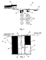
- Fig. 1 schematically illustrates the sewage purifying phytosystem 10, where sewage is received from a residential building 12. It is appreciated that the phytosystem 10 also operates in industrial applications. Moreover, the sewage from the residential building 12 is provided to the dynamic pretreatment system 14 of the present invention and pretreated sewage flows to the purifying container 16 of the present invention, where it is purified in accordance with the present description. When the sewage is purified into clean water it is either recycled and reused or released into the ground or to a final receiver for instance a pond 18.
- a purifying container 16 can be precast in many different outer shapes 20, as well as the septic tank 14 of which those in Fig. 1 are examples not intended to limit the invention only to those.
- the inner cylindrical wall 22 and a channel 24 of the container are also depicted in Fig.1 .
- the container 16 is mechanically constructed in the same manner as the septic tank 14, but without a lid and separating and deflecting walls as is depicted in Fig. 4 and Fig. 5 .
- the present invention or the first time applies composite light concrete with micro-fibrous reinforcement or glass-fiber reinforced plastic, GRP, or polyurethane to achieve an inexpensive container, comparable with other construction materials or prefabricated plastic containers, lightweight, watertight, durable, easy to transport and install with internal surface of low friction to ensure desirable hydraulic behavior of the circulating water.
- GRP glass-fiber reinforced plastic
- the entire phytosystem becomes less expensive, more affordable to communities, more reliable and the time required for manufacturing and onsite installation is significantly shorter than any other constructions of the same volume used so far.
- the present invention phytosystem with its containers 14, 16 differs from other biological treatment systems where sewage flow is linear, 'plug flow', as in WO 03042114 A1 , by applying a sequential flow.
- the number of channels and their dimension are designed for optimal treatment.
- Integrated biological beds placed in circulation channels mimic natural biocenoses in lakes and wetlands. Circulation channels comprise the system of joint vessels. It means that any inflow of sewage to the outer channel 24 causes an outflow of the equivalent amount of purified water from the internal cylindrical tank.
- Constantly forced flow of fluid close to the bottom of the circulation channels leads to recovery of heat transferred from the ground. It provides that the channels do not freeze at external temperatures as low as minus 33°C.
- An integrated biological bed consists of at least five species of aquatic and bog plants and several hundred species of invertebrates, coexisting with the plant rhizosphere. It results not only in breaking down organic matter but also in continuous consumption of particulate organic matter. Hence, contrary to other treatment systems, no excessive sludge or volatile suspended solids (VSS) are produced. Contrary to "low yield" VSS in effluent quoted in WO 03042114 A1 . Many species of invertebrates are emerging and in flying forms leave the open phytosystem, which contributes to the onside recycling of organic carbon and other essential nutrients exactly what takes place in open natural ecosystems.
- Pretreated sewage is pumped into the first, outer circulation channel of the phytosystem.
- volume of the outer channel will be approx. 50 m 3 including the bio-bed.
- the inflowing dose of sewage will be diluted 50 times with purified water in the channel just by making one full circle (25 m). This volume will enter the internal channel only after treatment in the bio-bed with sequential periods of intensive oxidation followed by controlled periods of anaerobic conditions. Every additional circulation channel increases the ratio of purified water to the dosed sewage.
- An extended surface area of one cubic meter of a bio-block alone is approx. 300 square meters and increases at least hundred times with increasing mass of macrophyte roots.
- a vortex mechanical device is installed according to the present invention.
- One embodiment of the present invention applies as a standard selected aquatic and bog plants of for instance the following genus: sedge (Carex), bulrush (Typha) and sweet-flag ( Acorus ), which in their extensive rhizosphaere provide key habitats for sustaining high invertebrate (protozoa) population. Invertebrate grazing prevents excessive biofilm growth and biomass accumulation.
- sedge Carex
- bulrush Teypha
- Acorus sweet-flag
- Invertebrate grazing prevents excessive biofilm growth and biomass accumulation.
- Two other plants, genus: water mynth (Mentha) and water-plantain (Alisma) can be added for their apparently beneficial role in biocenose development, due to root exudates of dissolved organic carbon and enzymes.
- the roots and rhizomes of the selected plants have beneficial effect on the microstructure of the biological bed and they stimulate development and growth of nitrifying bacteria.
- the phytosystem with its container can also utilize bamboo and other plants for economic and aesthetic purposes as well as for an improved treatment process.
- the present invention applies standardized prefabricated tubular bio-blocks with defined mechanical parameters like density, porosity and buoyancy, hence the functional parameters of the integrated biological bed (bio-bed) can be designed precisely.
- the present invention applies vortex principles for water movement for aeration and circulation of water, a unique functional flexibility of the entire phytosystem was achieved.
- Application of vortex improved desired aeration, intensive oxygenation and particle flotation within the phytosystem, it enhanced growth of the plant rhizosphere, it allowed for instant switching from aerobic to anaerobic conditions while utilizing a very low amount of external energy.
- Fig. 2 schematically illustrates a cross view of a multifunctional septic system (MSS) comprising a septic container 14 adapted to pretreatment of sewage in accordance with the present invention of the phytosystem.
- MSS multifunctional septic system
- the sewage from the residential building 12 is pre-treated in a pretreatment container 14 providing pretreated sewage to the phytosystem 10, where the sewage is further treated to be purified in accordance with desired quality norms.
- the sewage is purified into clean water in the purifying container 16 it can optionally be discharged to a final receiver, for instance a pond 18.
- a container 14 can be formed in many different outer shapes 20 of which those in Fig. 1 are examples not intended to limit the invention only to those.
- the inner cylindrical wall 37 of the container 14 is depicted in Fig. 2 .
- the container 14 is equipped with a raw sewage inlet 26, and an outlet 28 for pretreated sewage.
- the MSS is in one embodiment in a shape of a watertight cylindrical container 14, 200 cm in diameter, with an axially positioned inner compartment 38, 80 cm in diameter.
- a pump 40 is depicted in Fig. 2 , which stirs the sewage in the inner compartment 38 while dosing the sewage to the phytosystem.
- the entire construction is made out of precast composite concrete reinforced with polymeric microfibers or precast as a polyurethane container. Both the cylindrical container 14 and the inner compartment 38 are 200 cm high.
- the container has a bottom plate and a plastic lid.
- the inner compartment 38 is connected by a bypass 35, 10 cm in diameter situated above a lower ridge of the inner cylindrical wall 37 bypassing sewage water into the inner compartment 38 to be pumped out through an outlet 28 for pretreated sewage water.
- the adjacent channel 34 l s between transept walls: 30 and 32.
- One wall 30 is located next to the inlet of raw sewage 26 and is 200 cm high and 60 cm wide, and stretches water tightly from the top of the container 14 to the bottom of the same, attached between an outer wall 15 and an inner wall 37.
- the outer wall 15 and the inner wall 37 are making up an outer compartment/channel.
- the other transept wall 32 has length equal to 50 % of the wall 30 and is situated at the opposite side of the channel and serves as a deflector by dividing the outer compartment into two halves.
- the upper wall 32 deflecting fluids between the two halves of the outer compartment through an opening in the wall, and operating as a scum barrier, and the lower half connects both sides of the wall 30, 32 with a channel which allows for free movement of fluid while the upper half 32 prevents sewage scum from entering a bio-bed compartment.
- the wall 30 reaches from the bottom of the compartment to approx. the top of the compartment.
- a second deflecting transept wall 32 begins at the top of the compartment and leaves a specific opening above the bottom of the compartment in one embodiment of the present invention equal to 1/2 of the transept's length as a specific part of the total length of the transept. This is not the case in document KR 20030044647 where the opening in the transept wall is not serving as a deflecting mechanism.
- the system in KR 20030044647 operates on activated sludge, and there is no need for a scum barrier.
- the container 14 could be manufactured in the same manner as the container 16 as depicted in Fig. 4 and Fig. 5 regarding the inlet 26, outer compartment, inner compartment 38, bypass 35, and an outlet 28.
- composite light concrete with micro-fibrous reinforcement and polyurethane-polyvinyl is applied in accordance with the present invention, to achieve an inexpensive, compared to other construction materials or prefabricated plastic containers, lightweight, watertight, durable easy to transport and install compartment.
- this construction material By applying this construction material, the MSS became less expensive, more affordable to communities and more reliable.
- the present invention system 10 with its utilized containers 14, 16 differs from other pre-treatment systems where sewage flow is usually passive between the compartments.
- a deflected forced sewage flow in the functionally distinctly different compartments of the container 14 leads to excellent recovery of heat transferred from the ground and heat retained from the inflowing sewage. It provides that liquid does not freeze at external temperatures as low as minus 33°C. Processes of sedimentation, de-nitrification and phosphorus reduction are relatively stable. Hence, contrary to conventional septic tank systems, there is no excessive sludge accumulation.
- the functional parameters of the anoxic and aerated bio-bed can be designed precisely.
- the MSS offers an ideal solution to sewage flow between 1 and 10 m 3 /day prior to final biological treatment in the phytosystem 10 or can serve as the only mechanical-biological treatment in conjunction with discharge to soil drainage, wetlands, lagoons or ponds where final natural polishing of sewage may take place.
- Efficiency of treatment by the MSS is considerably higher than the current European water quality norms require.
- a prefabricated high porosity tubularfilling (300m 2 /m 3 ) is placed inside the internal tank 38.
- the filling serves as an additional aerobic bio-bed and as supporter for a submerged sewage dosing pump.
- the pump is equipped with a water level sensor and a timer and optionally with an air-jet aerator that can aerate the aerobic bio-bed below.
- the MSS is covered by a lid made out of reinforced polyethylene (HDPE) with manholes, 60 cm in diameter allowing access to the pump and 20 cm in diameter for evacuation of inorganic sediment.
- the lid may be equipped with a chimney allowing access to the tank when the MSS has to be placed deeper in the ground.
- the outlet pipe from the submerged pump is situated at the ridge of the MSS container.
- the horizontal outlet pipe leads pretreated sewage outside the system and it is connected with the vertical pipe by a rectangular shunt joint.
- Half of the cylindrical MSS between the transept walls serves as sedimentation chamber.
- the other half of the MSS is filled in by an anaerobic bio-bed that considerably upgrades processes of pretreatment and allows for optional recirculation of water treated in the PhytoSystem in order to intensify the process of denitrification.
- the volume of the anoxic bio-bed is 2 m 3 but the biologically active extended surface area exceeds 300m 2 /m 3 .
- Raw sewage undergoes a settlement process in the first half of the MSS where part of the solids will sediment and the other part will form surface scum that undergoes slow decomposition.
- Partly purified sewage moves on to the next compartment with the bio-bed where processes in the developed bio-film will treat it further.
- the bio-bed has an anaerobic character allowing for accelerated denitrification and biological reduction of phosphorus, especially when treated water from the phytosystem 10 is being recycled.
- the pretreated sewage After passing through the bio-bed, the pretreated sewage enters the internal tank with the submerged dosing pump. When the predetermined water level is reached, the sensor switches on the pump which pumps the sewage outside the container. On the way to the final discharge or further treatment in the phytosystem 10, the pretreated sewage can be aerated by an air-jet located on the vertical part of the outlet pipe.
- the MSS can be installed as an autonomous sewage treatment unit for one household, equipped with a bio-bed, own pump and aeration system. In such a set-up, pretreated sewage can be further treated by trench systems or soil bed drainage. It can also be discharged to ponds or lagoons with aquatic vegetation. An own pump system allows for discharge of pretreated sewage according to local conditions and requirements. Fig.
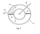
- FIG. 3 schematically illustrates a top view of a septic container 14 in Fig.2 for pretreatment of sewage in accordance with the present invention.
- a sedimentation compartment is situated under the lid 42 at the upper part in Fig.3 between the two transept walls 30, 32, whereby the wall 32 is a deflecting wall.
- the compartment beneath the upper compartment and under the lid 42 in Fig. 3 is a biological denitrification bed consisting of tubular netting.
- the internal cylindrical tank 38 consists of tubular netting and a fine-mesh netting forming the base for the submersible dosing pump 40 supplying pretreated sewage/wastewater to the conventional soil-based treatment or to the phytosystem - in such a case it can be named a "tandem system" (MSS + container 16).
- the wall 30 is a vertical watertight wall of the height equal the height of the container/tank 14.
- a deflecting wall 32 is approximately 1/2 of the wall 30 in one embodiment of the present invention. It forces the down-flow of sewage beneath the biological denitrification bed.
- the present invention offers a dynamic system 10 as a replacement of conventional passive systems, known as 2- or 3-compartment septic tanks, with all environmental advantages that follow the improvements described herein.
- Fig. 3 depicts a manhole 44 to provide access to maintain the dosing pump 40. Also a manhole 46 is depicted through which the inorganic sediment from the container 14 is sucked out of the container whenever necessary, for example every ten years for a household container.
- the septic container 14 can also be applied to store and pre-treat industrial wastewater prior to treatment in the phytosystem.
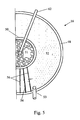
- Fig. 4 illustrates a container 16 with an outer wall 48, herein cylindrical but other shapes are possible, and the container 16 also has an inner cylindrical wall 50.
- the inner wall 50 forms an inner compartment 51, and the outer wall 48 forming an outer compartment-channel 52. Sewage water is inlet to the outer compartment 52 through an inlet 53 circulating the sewage water in the outer compartment 52 in accordance with the arrows in Fig. 4 .
- the outer compartment has three walls attached in a radius fashion to the outer wall 48 and the inner wall 50, whereby wall 54 is attached to the tank bottom and reaching approximately 20 cm below water level.
- each one are positioned on each side of the wall 54 reaching approximately up to the water level and ending approximately 20 cm from the bottom of the container, which allows water to flow between the walls 54, 56 in accordance with the arrows in Fig. 4 .
- This is an innovative embodiment allowing sewage water to re-circulate in the outer compartment 48.
- an air diffuser 58 creates an effect of an air-lift pump between walls 54 and 56, enhancing vortex and waterfall movement of water and the circulation in compartment 48.
- a whole 60 in the inner tank wall 50 acts as a bypass for treated sewage water to enter the inner compartment 51 and finally to an outlet of purified water shown in Fig. 5 .
- Fig. 5 it is schematically illustrates a container 16 according to Fig. 4 in a cut upper elevation view with an outer wall 48 and an inner wall 50 with their compartments 51, and 52, respectively.
- the circulation walls 54, 56 are depicted in an upper elevation view as well as an inlet 53 for sewage water and an outlet 62 for purified water to be transported for instance to a pond 18.
- the inner compartment 51 can in one embodiment of the present invention contain a predetermined amount of a mineral adsorber filling such as Phoslock® or Polonite® for the adsorption of the dissolved phosphorus in the outflowing purified water.
- the outer compartment 52 it contains a bio-bed in accordance with the present invention.
- the container 14 is located underground in such a way that the raw sewage can enter gravimetrically into the sediment compartment 42, Fig. 3 , which is not the case in document KR 20030044647 .
- the pretreated sewage leaves the internal compartment 51 via a predetermined dosing from a submerged pump (not shown) which is not the case in KR 20030044647 .
- the pump is not shown it could be inserted as the pump shown in Fig. 2 for the septic tank 14.
- a predetermined part of the purified water is gravimetrically recycled back to the denitrifying compartment for further denitrification of the nitrates. This is not the case in KR 20030044647 where permeate is vacuum pumped out of the system, and no further treatment of water is mentioned.
Landscapes
- Life Sciences & Earth Sciences (AREA)
- Engineering & Computer Science (AREA)
- Microbiology (AREA)
- Water Supply & Treatment (AREA)
- Hydrology & Water Resources (AREA)
- Environmental & Geological Engineering (AREA)
- Biodiversity & Conservation Biology (AREA)
- Chemical & Material Sciences (AREA)
- Organic Chemistry (AREA)
- Biotechnology (AREA)
- Botany (AREA)
- Biological Treatment Of Waste Water (AREA)
- Purification Treatments By Anaerobic Or Anaerobic And Aerobic Bacteria Or Animals (AREA)
Applications Claiming Priority (5)
| Application Number | Priority Date | Filing Date | Title |
|---|---|---|---|
| SE0800884 | 2008-04-17 | ||
| US4713208P | 2008-04-23 | 2008-04-23 | |
| SE0801268 | 2008-05-29 | ||
| US5837308P | 2008-06-03 | 2008-06-03 | |
| PCT/SE2009/000197 WO2009128765A1 (en) | 2008-04-17 | 2009-04-17 | A phytosystem for treatment of sewage |
Publications (3)
| Publication Number | Publication Date |
|---|---|
| EP2274245A1 EP2274245A1 (en) | 2011-01-19 |
| EP2274245A4 EP2274245A4 (en) | 2012-08-01 |
| EP2274245B1 true EP2274245B1 (en) | 2015-03-25 |
Family
ID=41199326
Family Applications (1)
| Application Number | Title | Priority Date | Filing Date |
|---|---|---|---|
| EP09732650.8A Revoked EP2274245B1 (en) | 2008-04-17 | 2009-04-17 | A phytosystem, its use and method for treatment of sewage |
Country Status (5)
| Country | Link |
|---|---|
| EP (1) | EP2274245B1 (zh) |
| CN (1) | CN102007076B (zh) |
| DK (1) | DK2274245T3 (zh) |
| WO (1) | WO2009128765A1 (zh) |
| ZA (1) | ZA201008192B (zh) |
Families Citing this family (9)
| Publication number | Priority date | Publication date | Assignee | Title |
|---|---|---|---|---|
| DE102010000159A1 (de) * | 2010-01-21 | 2011-07-28 | BORDA e.V. Bremen Overseas Research and Development Association, 28359 | Anlage und Verfahren zur anaeroben Behandlung organisch belasteter Abwässer |
| CN102415320B (zh) * | 2011-08-10 | 2013-01-09 | 玉溪市农业科学院 | 利用入湖河水漂浮栽培薄荷的方法 |
| CN106938880B (zh) * | 2017-05-16 | 2022-09-16 | 江西益洁环保技术有限公司 | 一种组合式农村生活污水处理系统 |
| CN107673428A (zh) * | 2017-11-16 | 2018-02-09 | 苏州纳贝通环境科技有限公司 | 一种水处理剂及其制备方法 |
| CN110589974B (zh) * | 2019-08-28 | 2022-03-15 | 江苏水工建设集团有限公司 | 一种应用于城市黑臭河道的治理系统及方法 |
| CN110803827B (zh) * | 2019-10-16 | 2022-03-01 | 江苏龙腾工程设计股份有限公司 | 一种菌藻填料强化组合式生态浮床及其净化水质的方法 |
| CN111960606A (zh) * | 2020-03-26 | 2020-11-20 | 中国水利水电科学研究院 | 一种污水处理装置 |
| IT202100014126A1 (it) * | 2021-05-28 | 2022-11-28 | Leonardo Bordi | Processo e impianto per ridurre le emissioni maleodoranti del percolato da discarica. |
| CN114349176A (zh) * | 2022-01-27 | 2022-04-15 | 欧秋香 | 一种加强挺水植物吸收污染物的人工湿地及其使用方法 |
Citations (11)
| Publication number | Priority date | Publication date | Assignee | Title |
|---|---|---|---|---|
| DE2148996B2 (de) | 1971-09-30 | 1978-03-23 | Max-Planck-Gesellschaft Zur Foerderung Der Wissenschaften E.V., 3400 Goettingen | Verfahren zur Abwasserreinigung |
| EP0458760A1 (en) | 1990-05-18 | 1991-11-27 | FOSFLEX s.r.l. | A process and plant for the biological purification of sewage |
| US5156742A (en) | 1992-02-25 | 1992-10-20 | Smith & Loveless, Inc. | Liquid treatment method and apparatus |
| US5618413A (en) | 1993-11-10 | 1997-04-08 | Ocean Arks International, Inc. | Ecological fluidized bed system |
| US5702593A (en) | 1994-02-14 | 1997-12-30 | Stormtreat Systems, Inc. | Stormwater treatment system/apparatus |
| US5863433A (en) | 1996-12-02 | 1999-01-26 | Tennessee Valley Authority United States Corp. | Reciprocating subsurface-flow constructed wetlands for improving wastewater treatment |
| US6159371A (en) | 1997-05-30 | 2000-12-12 | Albuquerque Public Schools District No. 12 | Constructed wetlands remediation system |
| KR20030044647A (ko) | 2001-11-30 | 2003-06-09 | 현대건설주식회사 | 일체형 침지식 멤브레인 폐수처리장치 |
| US20040035770A1 (en) | 2002-08-26 | 2004-02-26 | Edwards Haskell L. | Dynamically responsive aerobic to anoxic inter-zone flow control system for single vessel multi-zone bioreactor wastewater treatment plants |
| US20050040107A1 (en) | 2003-08-20 | 2005-02-24 | Kasparian Kaspar A. | Single vessel multi-zone wastewater bio-treatment system |
| WO2006099873A1 (en) | 2005-03-23 | 2006-09-28 | Expo-Net Danmark A/S | A contact filter block, a method of producing structural elements of a contact filter block and an apparatus for producing structural elements of a contact filter block |
Family Cites Families (12)
| Publication number | Priority date | Publication date | Assignee | Title |
|---|---|---|---|---|
| US3966608A (en) * | 1974-03-01 | 1976-06-29 | Ecodyne Corporation | Liquid treatment apparatus |
| AU618248B2 (en) * | 1987-02-17 | 1991-12-19 | Lucas Olaf Mueller | Water treatment tank |
| DK9300418U4 (da) * | 1993-09-13 | 1994-02-25 | Cowi Radgivende Ingeniorer As | Renseanlæg til fjernelse af næringssalte fra spildevand |
| GB2317168B (en) * | 1996-09-12 | 1998-11-04 | Balmoral Group | Sequential batch reactor |
| CN2286181Y (zh) * | 1997-03-07 | 1998-07-15 | 冶金工业部重庆钢铁设计研究院 | 生活污水处理一体化装置 |
| GB9720787D0 (en) * | 1997-09-30 | 1997-12-03 | Aw Creative Technologies Ltd | Activated sludge plant |
| DE19939917C1 (de) * | 1999-08-23 | 2001-04-05 | Joerg Huntmann | Mehrkammerklärgrube |
| BR0214175A (pt) * | 2001-11-14 | 2004-08-31 | Dharma Living Systems Inc | Sistema para tratamento de águas de rejeito, e, métodos para tratar águas de rejeito, e para projetar um sistema de tratamento de água de rejeito especìfico para um local |
| CN2550027Y (zh) * | 2002-06-10 | 2003-05-14 | 孙山 | 无动力油水分离器 |
| CN2575092Y (zh) * | 2002-11-02 | 2003-09-24 | 茂名学院 | 膜泥法污水处理装置 |
| US20040182781A1 (en) * | 2003-03-19 | 2004-09-23 | Davis Tommy Mack | Method and apparatus for in-situ microbial seeding of wastes |
| UA68252A (en) * | 2003-11-28 | 2004-07-15 | Ukrndiivodokanalproekt State R | A method for water decontamination |
-
2009
- 2009-04-17 EP EP09732650.8A patent/EP2274245B1/en not_active Revoked
- 2009-04-17 WO PCT/SE2009/000197 patent/WO2009128765A1/en active Application Filing
- 2009-04-17 CN CN2009801136839A patent/CN102007076B/zh active Active
- 2009-04-17 DK DK09732650.8T patent/DK2274245T3/da active
-
2010
- 2010-11-16 ZA ZA2010/08192A patent/ZA201008192B/en unknown
Patent Citations (12)
| Publication number | Priority date | Publication date | Assignee | Title |
|---|---|---|---|---|
| DE2148996B2 (de) | 1971-09-30 | 1978-03-23 | Max-Planck-Gesellschaft Zur Foerderung Der Wissenschaften E.V., 3400 Goettingen | Verfahren zur Abwasserreinigung |
| EP0458760A1 (en) | 1990-05-18 | 1991-11-27 | FOSFLEX s.r.l. | A process and plant for the biological purification of sewage |
| US5156742A (en) | 1992-02-25 | 1992-10-20 | Smith & Loveless, Inc. | Liquid treatment method and apparatus |
| US5618413A (en) | 1993-11-10 | 1997-04-08 | Ocean Arks International, Inc. | Ecological fluidized bed system |
| US5702593A (en) | 1994-02-14 | 1997-12-30 | Stormtreat Systems, Inc. | Stormwater treatment system/apparatus |
| US5863433A (en) | 1996-12-02 | 1999-01-26 | Tennessee Valley Authority United States Corp. | Reciprocating subsurface-flow constructed wetlands for improving wastewater treatment |
| US6159371A (en) | 1997-05-30 | 2000-12-12 | Albuquerque Public Schools District No. 12 | Constructed wetlands remediation system |
| KR20030044647A (ko) | 2001-11-30 | 2003-06-09 | 현대건설주식회사 | 일체형 침지식 멤브레인 폐수처리장치 |
| KR100422300B1 (ko) | 2001-11-30 | 2004-03-11 | 현대건설주식회사 | 일체형 침지식 멤브레인 폐수처리장치 |
| US20040035770A1 (en) | 2002-08-26 | 2004-02-26 | Edwards Haskell L. | Dynamically responsive aerobic to anoxic inter-zone flow control system for single vessel multi-zone bioreactor wastewater treatment plants |
| US20050040107A1 (en) | 2003-08-20 | 2005-02-24 | Kasparian Kaspar A. | Single vessel multi-zone wastewater bio-treatment system |
| WO2006099873A1 (en) | 2005-03-23 | 2006-09-28 | Expo-Net Danmark A/S | A contact filter block, a method of producing structural elements of a contact filter block and an apparatus for producing structural elements of a contact filter block |
Non-Patent Citations (8)
| Title |
|---|
| "Abwasserreinigung mit Pflanzen", INTERNET CITATION, 9 July 2003 (2003-07-09), pages 1, XP003025865, Retrieved from the Internet <URL:http://www.innovations-report.de/html/berichte/umwelt_naturschutz/bericht-19784.html> [retrieved on 20031223] * |
| "Constructed wetlands - structure and design. Application to climatic and environmental conditions in Europe", 20030401, 1 April 2003 (2003-04-01), pages 1 - 2, XP003025863 * |
| ANONYMOUS: "Decentralized system for sewage management in rural areas", CORDIS RTD-RESULTS/EUROPEAN COMMUNITIES,, 1 July 2003 (2003-07-01), pages 1, XP003025864 * |
| GUSTAF WIKLUND: "Phytosystem, ett alternativ for enskilda avlopp", DIPLOMA WORK AT LUND UNIVERSITY, March 2009 (2009-03-01), pages 1 - 63, XP055267095 |
| KOSIARSKA A: "Treatment plant as a garden", MURATOR, WYDAWNICTWO MURATOR SP. Z O.O, PL, vol. 10, 1 January 2007 (2007-01-01), pages 206 - 208, XP003025861, ISSN: 0239-6866 * |
| LAWACZ W ET AL: "Dynamic, closed loop, horizontal flow Phytoreactor", CONFERENCE ON CONSTRUCTED WETLANDS, 1 September 2004 (2004-09-01), pages 13, XP003025866 * |
| LAZAREK S: "Decentralized biological wastewater treatment system", NOWRA CONFERENCE,, 12 March 2007 (2007-03-12), pages 1 - 5, XP003025862 |
| LAZAREK: "Oczyszczalnia jak ogrod", MURATOR, no. 8, 2007, pages 206 - 212, XP055267109 |
Also Published As
| Publication number | Publication date |
|---|---|
| EP2274245A1 (en) | 2011-01-19 |
| CN102007076B (zh) | 2013-06-12 |
| WO2009128765A1 (en) | 2009-10-22 |
| ZA201008192B (en) | 2011-08-31 |
| DK2274245T3 (da) | 2015-06-22 |
| EP2274245A4 (en) | 2012-08-01 |
| CN102007076A (zh) | 2011-04-06 |
Similar Documents
| Publication | Publication Date | Title |
|---|---|---|
| EP2274245B1 (en) | A phytosystem, its use and method for treatment of sewage | |
| US7510649B1 (en) | Top loading vertical flow submerged bed wastewater treatment system | |
| CN102775025B (zh) | 高效低能耗城镇生活污水处理系统 | |
| Bani | Wastewater management | |
| US8764986B2 (en) | Submerged system and method for removal of undesirable substances from aqueous media | |
| CN108773970B (zh) | 漂浮式综合水处理设备、水处理方法及该设备的反洗方法 | |
| US20130277291A1 (en) | Integrated water processing technology | |
| CN101381155B (zh) | 一种用于污水净化和回用的生物生态组合的方法及装置 | |
| CN204324990U (zh) | 适用于入湖景观水体的多级生物滤池—生态塘净化系统 | |
| CN101786770B (zh) | 一种微动力移动床生活污水处理系统 | |
| CN101973679B (zh) | 一种分散式污水处理与再生工艺 | |
| CN105600951A (zh) | 一种湿地公园式生态水净化系统的构建方法 | |
| CN103265145B (zh) | 利用自然生物膜反应器净化低负荷低温河水的方法 | |
| CN201284274Y (zh) | 一种用于污水净化和回用的生物生态组合装置 | |
| CN100519449C (zh) | 速分生物污水处理方法及系统 | |
| CN102285715A (zh) | 用于榨菜废水处理的复合膜生物反应器 | |
| WO2004103511A2 (en) | Submerged ammonia removal system and method | |
| AU2014100523B4 (en) | Plastic honeycomb structure | |
| CN206486344U (zh) | 一种固定床mbr设备 | |
| Dzakpasu et al. | Constructed wetlands for urban water ecological improvement | |
| Kovács et al. | Ecoengineering tools: Passive artificial ecosystems | |
| CN209602313U (zh) | 一种兼具好氧生物处理的污水处理装置 | |
| Li et al. | Integrated Treatment Technology of Rural Domestic Sewage: Ten Cases of Integrated Sewage Treatment in Rural Area of China | |
| Sun et al. | Creation of a New Recreational Water Environment: The Beijing Olympic Park–More Than Ten Years of Experience | |
| Saleh et al. | A Study to Distinguish Between Wastewater Treatment Plants in Rural Egypt |
Legal Events
| Date | Code | Title | Description |
|---|---|---|---|
| PUAI | Public reference made under article 153(3) epc to a published international application that has entered the european phase |
Free format text: ORIGINAL CODE: 0009012 |
|
| 17P | Request for examination filed |
Effective date: 20101116 |
|
| AK | Designated contracting states |
Kind code of ref document: A1 Designated state(s): AT BE BG CH CY CZ DE DK EE ES FI FR GB GR HR HU IE IS IT LI LT LU LV MC MK MT NL NO PL PT RO SE SI SK TR |
|
| AX | Request for extension of the european patent |
Extension state: AL BA RS |
|
| DAX | Request for extension of the european patent (deleted) | ||
| TPAC | Observations filed by third parties |
Free format text: ORIGINAL CODE: EPIDOSNTIPA |
|
| A4 | Supplementary search report drawn up and despatched |
Effective date: 20120702 |
|
| RIC1 | Information provided on ipc code assigned before grant |
Ipc: C02F 3/28 20060101ALI20120626BHEP Ipc: C02F 3/30 20060101ALI20120626BHEP Ipc: C02F 3/32 20060101AFI20120626BHEP Ipc: C02F 3/06 20060101ALI20120626BHEP Ipc: C02F 3/22 20060101ALI20120626BHEP |
|
| 17Q | First examination report despatched |
Effective date: 20130517 |
|
| R17C | First examination report despatched (corrected) |
Effective date: 20130517 |
|
| GRAP | Despatch of communication of intention to grant a patent |
Free format text: ORIGINAL CODE: EPIDOSNIGR1 |
|
| RIC1 | Information provided on ipc code assigned before grant |
Ipc: C02F 3/22 20060101ALI20140923BHEP Ipc: C02F 3/32 20060101AFI20140923BHEP Ipc: C02F 103/00 20060101ALN20140923BHEP Ipc: C02F 3/30 20060101ALI20140923BHEP Ipc: C02F 3/28 20060101ALI20140923BHEP Ipc: C02F 3/06 20060101ALI20140923BHEP |
|
| INTG | Intention to grant announced |
Effective date: 20141023 |
|
| GRAS | Grant fee paid |
Free format text: ORIGINAL CODE: EPIDOSNIGR3 |
|
| GRAA | (expected) grant |
Free format text: ORIGINAL CODE: 0009210 |
|
| STAA | Information on the status of an ep patent application or granted ep patent |
Free format text: STATUS: THE PATENT HAS BEEN GRANTED |
|
| AK | Designated contracting states |
Kind code of ref document: B1 Designated state(s): AT BE BG CH CY CZ DE DK EE ES FI FR GB GR HR HU IE IS IT LI LT LU LV MC MK MT NL NO PL PT RO SE SI SK TR |
|
| REG | Reference to a national code |
Ref country code: GB Ref legal event code: FG4D |
|
| REG | Reference to a national code |
Ref country code: CH Ref legal event code: EP |
|
| REG | Reference to a national code |
Ref country code: IE Ref legal event code: FG4D |
|
| REG | Reference to a national code |
Ref country code: DE Ref legal event code: R096 Ref document number: 602009030186 Country of ref document: DE Effective date: 20150507 |
|
| REG | Reference to a national code |
Ref country code: AT Ref legal event code: REF Ref document number: 717782 Country of ref document: AT Kind code of ref document: T Effective date: 20150515 |
|
| REG | Reference to a national code |
Ref country code: DK Ref legal event code: T3 Effective date: 20150619 |
|
| REG | Reference to a national code |
Ref country code: SE Ref legal event code: TRGR |
|
| PG25 | Lapsed in a contracting state [announced via postgrant information from national office to epo] |
Ref country code: HR Free format text: LAPSE BECAUSE OF FAILURE TO SUBMIT A TRANSLATION OF THE DESCRIPTION OR TO PAY THE FEE WITHIN THE PRESCRIBED TIME-LIMIT Effective date: 20150325 Ref country code: FI Free format text: LAPSE BECAUSE OF FAILURE TO SUBMIT A TRANSLATION OF THE DESCRIPTION OR TO PAY THE FEE WITHIN THE PRESCRIBED TIME-LIMIT Effective date: 20150325 Ref country code: LT Free format text: LAPSE BECAUSE OF FAILURE TO SUBMIT A TRANSLATION OF THE DESCRIPTION OR TO PAY THE FEE WITHIN THE PRESCRIBED TIME-LIMIT Effective date: 20150325 |
|
| REG | Reference to a national code |
Ref country code: LT Ref legal event code: MG4D |
|
| PG25 | Lapsed in a contracting state [announced via postgrant information from national office to epo] |
Ref country code: LV Free format text: LAPSE BECAUSE OF FAILURE TO SUBMIT A TRANSLATION OF THE DESCRIPTION OR TO PAY THE FEE WITHIN THE PRESCRIBED TIME-LIMIT Effective date: 20150325 Ref country code: GR Free format text: LAPSE BECAUSE OF FAILURE TO SUBMIT A TRANSLATION OF THE DESCRIPTION OR TO PAY THE FEE WITHIN THE PRESCRIBED TIME-LIMIT Effective date: 20150626 |
|
| PG25 | Lapsed in a contracting state [announced via postgrant information from national office to epo] |
Ref country code: NL Free format text: LAPSE BECAUSE OF FAILURE TO SUBMIT A TRANSLATION OF THE DESCRIPTION OR TO PAY THE FEE WITHIN THE PRESCRIBED TIME-LIMIT Effective date: 20150325 |
|
| PG25 | Lapsed in a contracting state [announced via postgrant information from national office to epo] |
Ref country code: EE Free format text: LAPSE BECAUSE OF FAILURE TO SUBMIT A TRANSLATION OF THE DESCRIPTION OR TO PAY THE FEE WITHIN THE PRESCRIBED TIME-LIMIT Effective date: 20150325 Ref country code: CZ Free format text: LAPSE BECAUSE OF FAILURE TO SUBMIT A TRANSLATION OF THE DESCRIPTION OR TO PAY THE FEE WITHIN THE PRESCRIBED TIME-LIMIT Effective date: 20150325 Ref country code: SK Free format text: LAPSE BECAUSE OF FAILURE TO SUBMIT A TRANSLATION OF THE DESCRIPTION OR TO PAY THE FEE WITHIN THE PRESCRIBED TIME-LIMIT Effective date: 20150325 Ref country code: RO Free format text: LAPSE BECAUSE OF FAILURE TO SUBMIT A TRANSLATION OF THE DESCRIPTION OR TO PAY THE FEE WITHIN THE PRESCRIBED TIME-LIMIT Effective date: 20150325 Ref country code: PT Free format text: LAPSE BECAUSE OF FAILURE TO SUBMIT A TRANSLATION OF THE DESCRIPTION OR TO PAY THE FEE WITHIN THE PRESCRIBED TIME-LIMIT Effective date: 20150727 Ref country code: ES Free format text: LAPSE BECAUSE OF FAILURE TO SUBMIT A TRANSLATION OF THE DESCRIPTION OR TO PAY THE FEE WITHIN THE PRESCRIBED TIME-LIMIT Effective date: 20150325 |
|
| PG25 | Lapsed in a contracting state [announced via postgrant information from national office to epo] |
Ref country code: MC Free format text: LAPSE BECAUSE OF FAILURE TO SUBMIT A TRANSLATION OF THE DESCRIPTION OR TO PAY THE FEE WITHIN THE PRESCRIBED TIME-LIMIT Effective date: 20150325 Ref country code: PL Free format text: LAPSE BECAUSE OF FAILURE TO SUBMIT A TRANSLATION OF THE DESCRIPTION OR TO PAY THE FEE WITHIN THE PRESCRIBED TIME-LIMIT Effective date: 20150325 Ref country code: IS Free format text: LAPSE BECAUSE OF FAILURE TO SUBMIT A TRANSLATION OF THE DESCRIPTION OR TO PAY THE FEE WITHIN THE PRESCRIBED TIME-LIMIT Effective date: 20150725 |
|
| REG | Reference to a national code |
Ref country code: CH Ref legal event code: PL |
|
| REG | Reference to a national code |
Ref country code: DE Ref legal event code: R026 Ref document number: 602009030186 Country of ref document: DE |
|
| PLBI | Opposition filed |
Free format text: ORIGINAL CODE: 0009260 |
|
| PG25 | Lapsed in a contracting state [announced via postgrant information from national office to epo] |
Ref country code: CH Free format text: LAPSE BECAUSE OF NON-PAYMENT OF DUE FEES Effective date: 20150430 Ref country code: LI Free format text: LAPSE BECAUSE OF NON-PAYMENT OF DUE FEES Effective date: 20150430 Ref country code: IT Free format text: LAPSE BECAUSE OF FAILURE TO SUBMIT A TRANSLATION OF THE DESCRIPTION OR TO PAY THE FEE WITHIN THE PRESCRIBED TIME-LIMIT Effective date: 20150325 |
|
| REG | Reference to a national code |
Ref country code: FR Ref legal event code: ST Effective date: 20151231 |
|
| REG | Reference to a national code |
Ref country code: FR Ref legal event code: PLFP Year of fee payment: 7 |
|
| 26 | Opposition filed |
Opponent name: BRANN AB Effective date: 20151223 |
|
| PLAX | Notice of opposition and request to file observation + time limit sent |
Free format text: ORIGINAL CODE: EPIDOSNOBS2 |
|
| PG25 | Lapsed in a contracting state [announced via postgrant information from national office to epo] |
Ref country code: FR Free format text: LAPSE BECAUSE OF NON-PAYMENT OF DUE FEES Effective date: 20150526 |
|
| REG | Reference to a national code |
Ref country code: FR Ref legal event code: RN Effective date: 20160308 |
|
| REG | Reference to a national code |
Ref country code: FR Ref legal event code: PLFP Year of fee payment: 8 |
|
| REG | Reference to a national code |
Ref country code: FR Ref legal event code: FC Effective date: 20160322 |
|
| PG25 | Lapsed in a contracting state [announced via postgrant information from national office to epo] |
Ref country code: SI Free format text: LAPSE BECAUSE OF FAILURE TO SUBMIT A TRANSLATION OF THE DESCRIPTION OR TO PAY THE FEE WITHIN THE PRESCRIBED TIME-LIMIT Effective date: 20150325 |
|
| PGRI | Patent reinstated in contracting state [announced from national office to epo] |
Ref country code: FR Effective date: 20160322 |
|
| PLBB | Reply of patent proprietor to notice(s) of opposition received |
Free format text: ORIGINAL CODE: EPIDOSNOBS3 |
|
| REG | Reference to a national code |
Ref country code: AT Ref legal event code: UEP Ref document number: 717782 Country of ref document: AT Kind code of ref document: T Effective date: 20150325 |
|
| PG25 | Lapsed in a contracting state [announced via postgrant information from national office to epo] |
Ref country code: MT Free format text: LAPSE BECAUSE OF FAILURE TO SUBMIT A TRANSLATION OF THE DESCRIPTION OR TO PAY THE FEE WITHIN THE PRESCRIBED TIME-LIMIT Effective date: 20150325 |
|
| REG | Reference to a national code |
Ref country code: FR Ref legal event code: PLFP Year of fee payment: 9 |
|
| PG25 | Lapsed in a contracting state [announced via postgrant information from national office to epo] |
Ref country code: NO Free format text: LAPSE BECAUSE OF FAILURE TO SUBMIT A TRANSLATION OF THE DESCRIPTION OR TO PAY THE FEE WITHIN THE PRESCRIBED TIME-LIMIT Effective date: 20150625 Ref country code: HU Free format text: LAPSE BECAUSE OF FAILURE TO SUBMIT A TRANSLATION OF THE DESCRIPTION OR TO PAY THE FEE WITHIN THE PRESCRIBED TIME-LIMIT; INVALID AB INITIO Effective date: 20090417 Ref country code: BG Free format text: LAPSE BECAUSE OF FAILURE TO SUBMIT A TRANSLATION OF THE DESCRIPTION OR TO PAY THE FEE WITHIN THE PRESCRIBED TIME-LIMIT Effective date: 20150325 |
|
| PG25 | Lapsed in a contracting state [announced via postgrant information from national office to epo] |
Ref country code: CY Free format text: LAPSE BECAUSE OF FAILURE TO SUBMIT A TRANSLATION OF THE DESCRIPTION OR TO PAY THE FEE WITHIN THE PRESCRIBED TIME-LIMIT Effective date: 20150325 |
|
| PG25 | Lapsed in a contracting state [announced via postgrant information from national office to epo] |
Ref country code: TR Free format text: LAPSE BECAUSE OF FAILURE TO SUBMIT A TRANSLATION OF THE DESCRIPTION OR TO PAY THE FEE WITHIN THE PRESCRIBED TIME-LIMIT Effective date: 20150325 |
|
| PG25 | Lapsed in a contracting state [announced via postgrant information from national office to epo] |
Ref country code: LU Free format text: LAPSE BECAUSE OF NON-PAYMENT OF DUE FEES Effective date: 20150417 |
|
| PLCK | Communication despatched that opposition was rejected |
Free format text: ORIGINAL CODE: EPIDOSNREJ1 |
|
| STAA | Information on the status of an ep patent application or granted ep patent |
Free format text: STATUS: THE PATENT HAS BEEN GRANTED |
|
| APAH | Appeal reference modified |
Free format text: ORIGINAL CODE: EPIDOSCREFNO |
|
| APBM | Appeal reference recorded |
Free format text: ORIGINAL CODE: EPIDOSNREFNO |
|
| APBP | Date of receipt of notice of appeal recorded |
Free format text: ORIGINAL CODE: EPIDOSNNOA2O |
|
| REG | Reference to a national code |
Ref country code: FR Ref legal event code: PLFP Year of fee payment: 10 |
|
| APBQ | Date of receipt of statement of grounds of appeal recorded |
Free format text: ORIGINAL CODE: EPIDOSNNOA3O |
|
| PG25 | Lapsed in a contracting state [announced via postgrant information from national office to epo] |
Ref country code: MK Free format text: LAPSE BECAUSE OF FAILURE TO SUBMIT A TRANSLATION OF THE DESCRIPTION OR TO PAY THE FEE WITHIN THE PRESCRIBED TIME-LIMIT Effective date: 20150325 |
|
| PGFP | Annual fee paid to national office [announced via postgrant information from national office to epo] |
Ref country code: GB Payment date: 20200331 Year of fee payment: 12 Ref country code: SE Payment date: 20200331 Year of fee payment: 12 |
|
| PGFP | Annual fee paid to national office [announced via postgrant information from national office to epo] |
Ref country code: FR Payment date: 20200331 Year of fee payment: 12 Ref country code: DE Payment date: 20200420 Year of fee payment: 12 Ref country code: IE Payment date: 20200416 Year of fee payment: 12 Ref country code: DK Payment date: 20200420 Year of fee payment: 12 |
|
| PGFP | Annual fee paid to national office [announced via postgrant information from national office to epo] |
Ref country code: BE Payment date: 20200420 Year of fee payment: 12 |
|
| PGFP | Annual fee paid to national office [announced via postgrant information from national office to epo] |
Ref country code: AT Payment date: 20200420 Year of fee payment: 12 |
|
| APBU | Appeal procedure closed |
Free format text: ORIGINAL CODE: EPIDOSNNOA9O |
|
| REG | Reference to a national code |
Ref country code: DE Ref legal event code: R064 Ref document number: 602009030186 Country of ref document: DE Ref country code: DE Ref legal event code: R103 Ref document number: 602009030186 Country of ref document: DE |
|
| RDAF | Communication despatched that patent is revoked |
Free format text: ORIGINAL CODE: EPIDOSNREV1 |
|
| STAA | Information on the status of an ep patent application or granted ep patent |
Free format text: STATUS: PATENT REVOKED |
|
| RDAG | Patent revoked |
Free format text: ORIGINAL CODE: 0009271 |
|
| STAA | Information on the status of an ep patent application or granted ep patent |
Free format text: STATUS: PATENT REVOKED |
|
| REG | Reference to a national code |
Ref country code: FI Ref legal event code: MGE |
|
| 27W | Patent revoked |
Effective date: 20210318 |
|
| GBPR | Gb: patent revoked under art. 102 of the ep convention designating the uk as contracting state |
Effective date: 20210318 |
|
| REG | Reference to a national code |
Ref country code: SE Ref legal event code: ECNC |
|
| REG | Reference to a national code |
Ref country code: AT Ref legal event code: MA03 Ref document number: 717782 Country of ref document: AT Kind code of ref document: T Effective date: 20210318 |