EP2273589A1 - Membrane electrode assembly and fuel cell - Google Patents
Membrane electrode assembly and fuel cell Download PDFInfo
- Publication number
- EP2273589A1 EP2273589A1 EP09723722A EP09723722A EP2273589A1 EP 2273589 A1 EP2273589 A1 EP 2273589A1 EP 09723722 A EP09723722 A EP 09723722A EP 09723722 A EP09723722 A EP 09723722A EP 2273589 A1 EP2273589 A1 EP 2273589A1
- Authority
- EP
- European Patent Office
- Prior art keywords
- catalyst layer
- catalyst
- cathode
- electrode assembly
- micro
- Prior art date
- Legal status (The legal status is an assumption and is not a legal conclusion. Google has not performed a legal analysis and makes no representation as to the accuracy of the status listed.)
- Granted
Links
Images


Classifications
-
- H—ELECTRICITY
- H01—ELECTRIC ELEMENTS
- H01M—PROCESSES OR MEANS, e.g. BATTERIES, FOR THE DIRECT CONVERSION OF CHEMICAL ENERGY INTO ELECTRICAL ENERGY
- H01M8/00—Fuel cells; Manufacture thereof
- H01M8/10—Fuel cells with solid electrolytes
- H01M8/1004—Fuel cells with solid electrolytes characterised by membrane-electrode assemblies [MEA]
-
- H—ELECTRICITY
- H01—ELECTRIC ELEMENTS
- H01M—PROCESSES OR MEANS, e.g. BATTERIES, FOR THE DIRECT CONVERSION OF CHEMICAL ENERGY INTO ELECTRICAL ENERGY
- H01M4/00—Electrodes
- H01M4/86—Inert electrodes with catalytic activity, e.g. for fuel cells
- H01M4/8605—Porous electrodes
-
- H—ELECTRICITY
- H01—ELECTRIC ELEMENTS
- H01M—PROCESSES OR MEANS, e.g. BATTERIES, FOR THE DIRECT CONVERSION OF CHEMICAL ENERGY INTO ELECTRICAL ENERGY
- H01M4/00—Electrodes
- H01M4/86—Inert electrodes with catalytic activity, e.g. for fuel cells
- H01M4/90—Selection of catalytic material
- H01M4/92—Metals of platinum group
- H01M4/925—Metals of platinum group supported on carriers, e.g. powder carriers
-
- H—ELECTRICITY
- H01—ELECTRIC ELEMENTS
- H01M—PROCESSES OR MEANS, e.g. BATTERIES, FOR THE DIRECT CONVERSION OF CHEMICAL ENERGY INTO ELECTRICAL ENERGY
- H01M4/00—Electrodes
- H01M4/86—Inert electrodes with catalytic activity, e.g. for fuel cells
- H01M4/8647—Inert electrodes with catalytic activity, e.g. for fuel cells consisting of more than one material, e.g. consisting of composites
- H01M4/8652—Inert electrodes with catalytic activity, e.g. for fuel cells consisting of more than one material, e.g. consisting of composites as mixture
-
- Y—GENERAL TAGGING OF NEW TECHNOLOGICAL DEVELOPMENTS; GENERAL TAGGING OF CROSS-SECTIONAL TECHNOLOGIES SPANNING OVER SEVERAL SECTIONS OF THE IPC; TECHNICAL SUBJECTS COVERED BY FORMER USPC CROSS-REFERENCE ART COLLECTIONS [XRACs] AND DIGESTS
- Y02—TECHNOLOGIES OR APPLICATIONS FOR MITIGATION OR ADAPTATION AGAINST CLIMATE CHANGE
- Y02E—REDUCTION OF GREENHOUSE GAS [GHG] EMISSIONS, RELATED TO ENERGY GENERATION, TRANSMISSION OR DISTRIBUTION
- Y02E60/00—Enabling technologies; Technologies with a potential or indirect contribution to GHG emissions mitigation
- Y02E60/30—Hydrogen technology
- Y02E60/50—Fuel cells
Definitions
- the present invention relates to a fuel cell for generating electric power by an electrochemical reaction between hydrogen and oxygen.
- a polymer electrolyte fuel cell which has a basic structure of a solid polymer electrolyte membrane disposed between a fuel electrode and an air electrode, generates power through an electrochemical reaction as described below by supplying a fuel gas containing hydrogen to the fuel electrode and an oxidant gas containing oxygen to the air electrode.
- Fuel electrode H 2 ⁇ 2H + +2e - (1)
- Air electrode (1/2) O 2 +2H + +2e - ⁇ 7H 2 O (2)
- the anode and the cathode have each a stacked structure of a catalyst layer and a gas diffusion layer.
- a fuel cell is composed of catalyst layers of the respective electrodes disposed counter to each other in such a manner as to hold a solid polymer membrane therebetween.
- the catalyst layer is a layer of a catalyst or carbon particles carrying a catalyst bound together by an ion-exchange resin.
- the gas diffusion layer serves as a passage for the oxidant gas or the fuel gas.
- the hydrogen contained in the supplied fuel is decomposed into hydrogen ions and electrons as expressed in the above formula (1).
- the hydrogen ions travel inside the solid polymer electrolyte membrane toward the air electrode, whereas the electrons travel through an external circuit to the air electrode.
- the oxygen contained in the oxidant gas supplied thereto reacts with the hydrogen ions and electrons having come from the fuel electrode to produce water as expressed in the above formula (2). In this manner, the electrons travel from the fuel electrode toward the air electrode in the external circuit, so that the electric power is extracted therefrom (See Patent Document 1).
- Patent Document 1 Japanese Patent Publication No. 2002-203569 .
- the present invention has been made in view of the foregoing problems, and a purpose thereof is to provide a technology capable of improving the gas diffusibility of cathode catalyst layers and raising the cell voltage.
- the membrane electrode assembly includes: an electrolyte membrane; an anode disposed on one face of the electrolyte membrane; and a cathode disposed on the other face of the electrolyte membrane, wherein the cathode contains a catalyst layer such that the ratio of a pore volume in a second micro-pore diameter over a pore volume in a first micro-pore diameter is in a range of 3.8 to 8.3, the first micro-pore diameter ranging from 0.01 ⁇ m to less than 0.1 ⁇ m and the second micro-pore diameter ranging from 0.1 ⁇ m to less than 1 ⁇ m.
- the catalyst layer may contain a platinum-alloy-supported catalyst.
- the catalyst layer may contain an ion conductor whose ion-exchange group equivalent weight (EW value) is less than or equal to 800.
- Another embodiment of the present invention relates to a fuel cell.
- the fuel cell has a membrane electrode assembly according to any one of the above-described embodiments.
- the present invention enhances the gas diffusibility of cathode catalyst layers and raises the cell voltage.
- FIG. 1 is a perspective view schematically illustrating a structure of a fuel cell 10 according to an embodiment of the present invention.
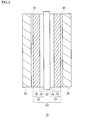
- FIG. 2 is a cross-sectional view taken on the dotted line A-A of FIG. 1 .
- the fuel cell 10 is comprised of a plate-like membrane electrode assembly 50, a separator 34 on one side of the membrane electrode assembly 50, and a separator 36 on the other side thereof. Although only one membrane electrode assembly 50 is shown in this example, the fuel cell 10 may be composed of a plurality of stacked membrane electrode assemblies 50 with separators 34 or separators 36 disposed therebetween.
- the membrane electrode assembly 50 includes a solid polymer electrolyte membrane 20, an anode 22, and a cathode 24.
- the anode 22 has a stacked body comprised of a catalyst layer 26 and a gas diffusion layer 28.
- the cathode 24 has a stacked body comprised of a catalyst layer 30 and a gas diffusion layer 32.
- the catalyst layer 26 of the anode 22 and the catalyst layer 30 of the cathode 24 are disposed counter to each other with the solid polymer electrolyte membrane 20 held therebetween.
- the separator 34 on the anode 22 side is provided with gas channels 38. From a manifold (not shown) for supplying fuel, the fuel gas is distributed to the gas channels 38 and supplied to the membrane electrode assembly 50 through the gas channels 38. Similarly, the separator 36 on the cathode 24 side is provided with gas channels 40.
- the oxidant gas is distributed to the gas channels 40 and supplied to the membrane electrode assembly 50 through the gas channels 40. More specifically, when the fuel cell 10 is operating, the fuel gas, such as hydrogen gas, is supplied to the anode 22 as the fuel gas flows downward through the gas channels 38 along the surface of the gas diffusion layer 28.
- the fuel gas such as hydrogen gas
- the oxidant gas such as air
- the oxidant gas is supplied to the cathode 24 as the oxidant gas flows downward through the gas channels 40 along the surface of the gas diffusion layer 32.
- the hydrogen gas is supplied to the catalyst layer 26 through the gas diffusion layer 28, the hydrogen in the gas is turned into protons, and the protons travel through the solid polymer electrolyte membrane 20 to the cathode 24 side. Electrons released at this time move to an external circuit and then flow into the cathode 24 from the external circuit.
- air is supplied to the catalyst layer 30 through the gas diffusion layer 32, the oxygen combines with the protons, thus turning into water. As a result, electrons flow from the anode 22 to the cathode 24 in the external circuit, so that the electric power can be extracted therefrom.
- the solid polymer electrolyte membrane 20 which displays an excellent ion conductivity in a damp condition, functions as an ion-exchange membrane that allows transfer of protons between the anode 22 and the cathode 24.
- the solid polymer electrolyte membrane 20 may be formed of a solid polymer material of fluorine-containing polymer or nonfluorine polymer, which may be, for example, a sulfonic acid type perfluorocarbon polymer, a polysulfone resin, or a perfluorocarbon polymer having a phosphonic acid group or carboxylic acid group.
- sulfonic acid type perfluorocarbon polymer is Nafion ionomer dispersion (made by DuPont: registered trademark) 112.
- nonfluorine polymer may be a sulfonated aromatic polyether ether ketone or polysulfone.
- the film thickness of the solid polymer electrolyte membrane 20 is typically 50 ⁇ m.
- the catalyst layer 26 constituting a part of the anode 22 is comprised of an ion conductor (ion-exchange resin) and carbon particles supporting a catalyst, namely catalyst-supporting carbon particles.
- the thickness of the catalyst layer 26 is typically 10 ⁇ m.
- the ion conductor plays a role of connecting the carbon particles supporting an alloy catalyst with the solid polymer electrolyte membrane 20 to allow the transfer of protons between the two.
- the ion conductor may be formed of a polymer material similar to the solid polymer electrolyte membrane 20.
- the alloy catalyst used for the catalyst layer 26 may be, for example, a precious metal and ruthenium.
- a precious metal used for the alloy catalyst may be, for example, platinum, palladium, or the like.
- the carbon particles supporting such an alloy catalyst may be acetylene black, ketjen black, carbon nanotube, carbon nano-onion, or the like.
- the ion-exchange group equivalent weight (EW value) of the ion conductor is preferably 800 or below. If the EW value is set accordingly, a sufficient proton conductivity can be obtained and the water content of the catalyst layer 26 can be increased.
- the gas diffusion layer 28 constituting another part of the anode 22 includes an anode gas diffusion substrate and a microporous layer applied to the anode gas diffusion substrate.
- the anode gas diffusion substrate is made of a porous material having an electron conductivity, which may, for instance, be a carbon paper or woven or nonwoven cloth of carbon.
- the microporous layer applied to the anode gas diffusion substrate is a pasty material derived by kneading an electrically conductive powder and a water repellent agent together.
- the electrically conductive powder may be carbon black, for instance.
- the water repellent agent that can be used may be a fluorine-based resin such as tetrafluoroethylene resin (polytetrafluoroethylene (PTFE)).
- PTFE polytetrafluoroethylene
- the water repellent agent preferably has a binding property.
- the binding property meant here is a property that can create a condition of cohesive bond of less viscous and easily crumbling materials together. With the cohesiveness of the water repellent agent, the electrically conductive powder and the water repellent agent can be kneaded together into a paste.
- the catalyst layer 30 constituting a part of the cathode 24 is comprised of an ion conductor (ion-exchange resin) and carbon particles supporting a catalyst, namely catalyst-supporting carbon particles.
- the ion conductor plays a role of connecting the carbon particles supporting a catalyst with the solid polymer electrolyte membrane 20 to allow the transfer of protons between the two.
- the ion conductor may be formed of a polymer material similar to the solid polymer electrolyte membrane 20.
- the catalyst to be supported may be platinum-alloy, for instance.
- a metal used for the platinum-alloy may be, for example, cobalt, nickel, iron, manganese, iridium, and the like.
- the carbon particles supporting such an alloy catalyst may be acetylene black, ketjen black, carbon nanotube, carbon nano-onion, or the like.
- the catalyst layer 30 has micro pores whose diameter lies in the range of 0.01 ⁇ m to 1 ⁇ m.
- a micro-pore diameter (size) ranging from 0.01 ⁇ m to less than 0.1 ⁇ m is called a first micro-pore diameter.
- a micro-pore diameter ranging from 0.1 ⁇ m to less than 1 ⁇ m is called a second micro-pore diameter.
- the micro-pore diameter may be measured using a mercury intrusion technique, for instance.
- the ratio (P2/P1) of the pore volume P2 (ml/g) per gram of catalyst layer in the second micro-pore diameter over the pore volume P1 per gram of catalyst layer in the first micro-pore diameter is preferably in a range of 3.8 to 8.3 (3.8 ⁇ (P2/P1) ⁇ 8.3) and more preferably in a range of 4.0 to 7.0 (4.0 ⁇ (P2/P1) ⁇ 7.0).
- the ratio P2/P1 is about 3.5 to about 3.7, and the output voltage is about 745 mV. Setting the ratio P2/P1 to 3.8 or above results in an improvement of the gas diffusibility, so that an output voltage higher than that of a fuel cell using the conventional catalyst layer can be obtained.
- the ratio P2/P1 becomes larger than 8.3, a clogged drain is more likely to occur and therefore the output voltage will be lower than that of the fuel cell using the conventional catalyst layer. Setting the ratio P2/P1 in a range of 4.0 to 7.0 suppresses the adverse effect of clogged drain and, at the same time, an output voltage higher, by 4% to 6%, than that of the fuel cell using the conventional catalyst layer can be obtained.
- Pores each having the first micro-pore diameter are formed by gaps (spaces) formed among catalyst-supporting carbon particles.
- pores each having the second micro-pore diameter are formed, for example, such that a foaming agent and/or a pore forming agent are/is added to the catalyst layer and then the foaming agent and/or pore forming agent are/is removed by thermal decomposition or the like.
- the second micro-pore diameter can be adjusted by the median size of the foaming agent and/or pore forming agent. For example, if the median size of the foaming agent ranges from 0.01 ⁇ m to 100 ⁇ m, pores whose size ranges from 0.1 ⁇ m to less than 1 ⁇ m can be formed in the catalyst layer 30.
- the pore volume per gram of catalyst layer can be adjusted by adjusting the amount of foaming agent and the like to be added.
- the amount of forming agent and the like to be added is preferably 0.01 wt.% to 20 wt.% of the total weight of the catalyst.
- the gas diffusion layer 32 constituting another part of the cathode 24 includes a cathode gas diffusion substrate and a microporous layer applied to the cathode gas diffusion substrate.
- the cathode gas diffusion substrate is made of a porous material having an electron conductivity, which may, for instance, be a carbon paper or woven or nonwoven cloth of carbon.
- the microporous layer applied to the cathode gas diffusion substrate is a pasty material derived by kneading an electrically conductive powder and a water repellent agent together.
- the electrically conductive powder may be carbon black, for instance.
- the water repellent agent that can be used may be a fluorine-based resin such as tetrafluoroethylene resin (polytetrafluoroethylene). Note that the water repellent agent preferably has a binding property. With the cohesiveness of the water repellent agent, the electrically conductive powder and the water repellent agent can be kneaded together into a paste.
- a sufficient gas diffusibility of the catalyst layer 30 constituting the cathode 24 can be achieved and moreover the output voltage of the fuel cell 10 can be increased.
- a platinum alloy catalyst which is subject to water flooding, is used for the catalyst layer 30 or an ion conductor whose EW value, namely the water content, is low is used for the catalyst layer 30, a sufficient gas diffusibility of the catalyst layer 30 can be achieved.
- Platinum-cobalt-supporting carbon (element ratio of platinum to cobalt is 3 : 1, Tanaka Kikinzoku Kogyo) is used as the cathode catalyst.
- the second micro-pore diameter can be adjusted by the median size of the foaming agent to be added.
- the amount of foaming agent to be added is preferably 0.01 wt.% to 20 wt.% of the weight of the catalyst and more preferably 0.5 wt.% to 1 wt.% thereof.
- This catalyst dispersion solution is stirred and dispersed ultrasonically for more than an hour using an ultrasonic stirrer.
- a predetermined amount of SS700 solution is diluted with the same amount of ultrapure water as SS700 and stirred by means of a glass rod for three minutes. Then, the SS700 solution diluted with water is dispersed ultrasonically for an hour using an ultrasonic cleaner so as to obtaine the SS700 solution. Then, the SS700 solution is slowly dripped into the catalyst dispersion solution. During the dripping, the catalyst dispersion solution with the SS700 solution dripped thereinto is continuously stirred using the ultrasonic stirrer.
- a 10 g mixed solution of 1-propanol and 1-butanol (the weight ratio being 1 : 1) is dripped thereinto and the thus obtained solution is used as the cathode catalyst slurry.
- the liquid temperature is adjusted to be about 60°C throughout the process and the ethanol is evaporated and removed.
- the catalyst slurry fabricated by the above-described method is applied to the gas diffusion layer, with the microporous layer attached thereto, fabricated by Vulcan XC72, using a screen printing method (150 meshes). Then the catalyst slurry applied thereto is dried at a temperature of 80°C for three hours and undergoes a heat treatment for forty five minutes.
- a method for manufacturing a catalyst slurry for the anode catalyst layer is the same as the method for manufacturing the cathode catalyst slurry except that platinum-ruthenium-supporting carbon (TEC61E54, Tanaka Kikinzoku Kogyo) is used as the anode catalyst and that no foaming agent is used.
- TEC61E54 platinum-ruthenium-supporting carbon
- SS700 is used as the ion conductor.
- the catalyst slurry for a first catalyst layer of anode and the catalyst slurry for a second catalyst layer of anode fabricated by the above-described method are applied, in this order, to the gas diffusion layer, with the microporous layer attached thereto, fabricated by Vulcan XC72, using a screen printing method (150 meshes). Then the catalyst slurries applied thereto are dried at a temperature of 80°C for three hours and undergoes a heat treatment for forty five minutes.
- Hot pressing is performed with the solid polymer electrolyte membrane held between the anode and the cathode fabricated by the above-described methods.
- Aciplex registered trademark
- SF7201x Asahi Kasei Chemicals Corp.
- the solid polymer electrolyte membrane and the cathode are hot-pressed so as to fabricate the membrane electrode assembly.
- the membrane electrode assembly was manufactured according to the above-described method for fabricating the membrane electrode assembly.
- the ratio (P2/P1) of the pore volume P2 (ml/g) per gram of catalyst layer in the second micro-pore diameter over the pore volume P1 per gram of catalyst layer in the first micro-pore diameter is varied in the manufacturing of the membrane electrode assembly, and the cell voltage in each varied instance is measured.
- FIG. 3 is a graph showing a relation between the ratio (P2/P1) of the pore volume P2 in the second micro-pore diameter over the pore volume P1 in the first micro-pore diameter and the voltage obtained at each varied instance. As shown in FIG. 3 , it is verified that, as compared with the output voltage of 745 mV in a conventional case of about 3.5 to 3.7, the voltage becomes higher in a range of the ratio P2/P1 distributed in the example embodiment between 3.8 and 8.3 (both inclusive).
- the ratio P2/P1 for the cathode layer is prescribed in a range of 3.8 to 8.3.
- the ratio P2/P1 for the cathode layer is prescribed in a range of 3.8 to 8.3, too. According to this modification, the gas diffusibility of anode catalyst layers can be improved
- the present invention contributes to an improvement in the gas diffusibility of cathode catalyst layers used in a fuel cell.
Abstract
Description
- The present invention relates to a fuel cell for generating electric power by an electrochemical reaction between hydrogen and oxygen.
- Recently much attention has been focused on fuel cells that feature not only high energy conversion efficiency but also no hazardous substance produced by the electricity-generating reaction. Known as one of such fuel cells is the polymer electrolyte fuel cell which operates at a low temperature of 100°C or below.
- A polymer electrolyte fuel cell, which has a basic structure of a solid polymer electrolyte membrane disposed between a fuel electrode and an air electrode, generates power through an electrochemical reaction as described below by supplying a fuel gas containing hydrogen to the fuel electrode and an oxidant gas containing oxygen to the air electrode.
-
Fuel electrode : H2→2H++2e- (1)
Air electrode : (1/2) O2+2H++2e-→7H2O (2)
The anode and the cathode have each a stacked structure of a catalyst layer and a gas diffusion layer. And a fuel cell is composed of catalyst layers of the respective electrodes disposed counter to each other in such a manner as to hold a solid polymer membrane therebetween. The catalyst layer is a layer of a catalyst or carbon particles carrying a catalyst bound together by an ion-exchange resin. The gas diffusion layer serves as a passage for the oxidant gas or the fuel gas. - At the anode, the hydrogen contained in the supplied fuel is decomposed into hydrogen ions and electrons as expressed in the above formula (1). Of them, the hydrogen ions travel inside the solid polymer electrolyte membrane toward the air electrode, whereas the electrons travel through an external circuit to the air electrode. At the cathode, on the other hand, the oxygen contained in the oxidant gas supplied thereto reacts with the hydrogen ions and electrons having come from the fuel electrode to produce water as expressed in the above formula (2). In this manner, the electrons travel from the fuel electrode toward the air electrode in the external circuit, so that the electric power is extracted therefrom (See Patent Document 1).
[Patent Document 1] Japanese Patent Publication No.2002-203569 - The water retentivity and the gas diffusibility are required of a cathode catalyst layer. However, as the water retentivity rises, there will be an increased likelihood of a clogged drain and therefore the gas deffusibility is hindered. In the light of this, establishing a technology that satisfies both the water retentivity and the gas diffusibility has been a major issue.
- The present invention has been made in view of the foregoing problems, and a purpose thereof is to provide a technology capable of improving the gas diffusibility of cathode catalyst layers and raising the cell voltage.
- One embodiment of the present invention relates to a membrane electrode assembly. The membrane electrode assembly includes: an electrolyte membrane; an anode disposed on one face of the electrolyte membrane; and a cathode disposed on the other face of the electrolyte membrane, wherein the cathode contains a catalyst layer such that the ratio of a pore volume in a second micro-pore diameter over a pore volume in a first micro-pore diameter is in a range of 3.8 to 8.3, the first micro-pore diameter ranging from 0.01 µm to less than 0.1 µm and the second micro-pore diameter ranging from 0.1 µm to less than 1 µm.
- By employing the membrane electrode assembly according to this embodiment, a sufficient gas diffusibility of catalyst layer constituting the cathode can be achieved and consequently the output voltage can be increased.
- In the membrane electrode assembly according to the above-described embodiment, the catalyst layer may contain a platinum-alloy-supported catalyst. The catalyst layer may contain an ion conductor whose ion-exchange group equivalent weight (EW value) is less than or equal to 800.
- Another embodiment of the present invention relates to a fuel cell. The fuel cell has a membrane electrode assembly according to any one of the above-described embodiments.
- It is to be noted that any arbitrary combinations or rearrangement, as appropriate, of the aforementioned constituting elements and so forth are all effective as and encompassed by the embodiments of the present invention.
- The present invention enhances the gas diffusibility of cathode catalyst layers and raises the cell voltage.
-
-
FIG. 1 is a perspective view schematically illustrating a structure of afuel cell 10 according to an embodiment of the present invention. -
FIG. 2 is a cross-sectional view taken on the dotted line A-A ofFIG. 1 . -
FIG. 3 is a graph showing a relationship between the ratio (P2/P1) of a pore volume in a second micro-pore diameter over a pore volume in a first micro-pore diameter. -
- 10
- Fuel cell
- 12
- Solid polymer electrolyte membrane
- 22
- Anode
- 24
- Cathode
- 26, 30
- Catalyst layers
- 28, 32
- Gas diffusion layers
- 50
- Membrane electrode assembly
- Hereinbelow, the embodiments will be described with reference to the accompanying drawings. Note that the identical components are given the identical reference numerals in all accompanying Figures and the repeated description thereof will be omitted as appropriate.
-
FIG. 1 is a perspective view schematically illustrating a structure of afuel cell 10 according to an embodiment of the present invention.FIG. 2 is a cross-sectional view taken on the dotted line A-A ofFIG. 1 . Thefuel cell 10 is comprised of a plate-likemembrane electrode assembly 50, aseparator 34 on one side of themembrane electrode assembly 50, and aseparator 36 on the other side thereof. Although only onemembrane electrode assembly 50 is shown in this example, thefuel cell 10 may be composed of a plurality of stackedmembrane electrode assemblies 50 withseparators 34 orseparators 36 disposed therebetween. Themembrane electrode assembly 50 includes a solidpolymer electrolyte membrane 20, ananode 22, and acathode 24. - The
anode 22 has a stacked body comprised of acatalyst layer 26 and agas diffusion layer 28. On the other hand, thecathode 24 has a stacked body comprised of acatalyst layer 30 and agas diffusion layer 32. Thecatalyst layer 26 of theanode 22 and thecatalyst layer 30 of thecathode 24 are disposed counter to each other with the solidpolymer electrolyte membrane 20 held therebetween. - The
separator 34 on theanode 22 side is provided withgas channels 38. From a manifold (not shown) for supplying fuel, the fuel gas is distributed to thegas channels 38 and supplied to themembrane electrode assembly 50 through thegas channels 38. Similarly, theseparator 36 on thecathode 24 side is provided withgas channels 40. - From a manifold (not shown) for supplying an oxidant, the oxidant gas is distributed to the
gas channels 40 and supplied to themembrane electrode assembly 50 through thegas channels 40. More specifically, when thefuel cell 10 is operating, the fuel gas, such as hydrogen gas, is supplied to theanode 22 as the fuel gas flows downward through thegas channels 38 along the surface of thegas diffusion layer 28. - At the same time, when the
fuel cell 10 is operating, the oxidant gas, such as air, is supplied to thecathode 24 as the oxidant gas flows downward through thegas channels 40 along the surface of thegas diffusion layer 32. As the hydrogen gas is supplied to thecatalyst layer 26 through thegas diffusion layer 28, the hydrogen in the gas is turned into protons, and the protons travel through the solidpolymer electrolyte membrane 20 to thecathode 24 side. Electrons released at this time move to an external circuit and then flow into thecathode 24 from the external circuit. On the other hand, as air is supplied to thecatalyst layer 30 through thegas diffusion layer 32, the oxygen combines with the protons, thus turning into water. As a result, electrons flow from theanode 22 to thecathode 24 in the external circuit, so that the electric power can be extracted therefrom. - The solid
polymer electrolyte membrane 20, which displays an excellent ion conductivity in a damp condition, functions as an ion-exchange membrane that allows transfer of protons between theanode 22 and thecathode 24. The solidpolymer electrolyte membrane 20 may be formed of a solid polymer material of fluorine-containing polymer or nonfluorine polymer, which may be, for example, a sulfonic acid type perfluorocarbon polymer, a polysulfone resin, or a perfluorocarbon polymer having a phosphonic acid group or carboxylic acid group. One example of a sulfonic acid type perfluorocarbon polymer is Nafion ionomer dispersion (made by DuPont: registered trademark) 112. Also, examples of nonfluorine polymer may be a sulfonated aromatic polyether ether ketone or polysulfone. The film thickness of the solidpolymer electrolyte membrane 20 is typically 50 µm. - The
catalyst layer 26 constituting a part of theanode 22 is comprised of an ion conductor (ion-exchange resin) and carbon particles supporting a catalyst, namely catalyst-supporting carbon particles. The thickness of thecatalyst layer 26 is typically 10 µm. The ion conductor plays a role of connecting the carbon particles supporting an alloy catalyst with the solidpolymer electrolyte membrane 20 to allow the transfer of protons between the two. The ion conductor may be formed of a polymer material similar to the solidpolymer electrolyte membrane 20. - The alloy catalyst used for the
catalyst layer 26 may be, for example, a precious metal and ruthenium. A precious metal used for the alloy catalyst may be, for example, platinum, palladium, or the like. Also, the carbon particles supporting such an alloy catalyst may be acetylene black, ketjen black, carbon nanotube, carbon nano-onion, or the like. - The ion-exchange group equivalent weight (EW value) of the ion conductor is preferably 800 or below. If the EW value is set accordingly, a sufficient proton conductivity can be obtained and the water content of the
catalyst layer 26 can be increased. - The
gas diffusion layer 28 constituting another part of theanode 22 includes an anode gas diffusion substrate and a microporous layer applied to the anode gas diffusion substrate. Preferably, the anode gas diffusion substrate is made of a porous material having an electron conductivity, which may, for instance, be a carbon paper or woven or nonwoven cloth of carbon. - The microporous layer applied to the anode gas diffusion substrate is a pasty material derived by kneading an electrically conductive powder and a water repellent agent together. The electrically conductive powder may be carbon black, for instance. The water repellent agent that can be used may be a fluorine-based resin such as tetrafluoroethylene resin (polytetrafluoroethylene (PTFE)). Note that the water repellent agent preferably has a binding property. The binding property meant here is a property that can create a condition of cohesive bond of less viscous and easily crumbling materials together. With the cohesiveness of the water repellent agent, the electrically conductive powder and the water repellent agent can be kneaded together into a paste.
- The
catalyst layer 30 constituting a part of thecathode 24 is comprised of an ion conductor (ion-exchange resin) and carbon particles supporting a catalyst, namely catalyst-supporting carbon particles. The ion conductor plays a role of connecting the carbon particles supporting a catalyst with the solidpolymer electrolyte membrane 20 to allow the transfer of protons between the two. The ion conductor may be formed of a polymer material similar to the solidpolymer electrolyte membrane 20. The catalyst to be supported may be platinum-alloy, for instance. A metal used for the platinum-alloy may be, for example, cobalt, nickel, iron, manganese, iridium, and the like. Also, the carbon particles supporting such an alloy catalyst may be acetylene black, ketjen black, carbon nanotube, carbon nano-onion, or the like. - The
catalyst layer 30 has micro pores whose diameter lies in the range of 0.01 µm to 1 µm. A micro-pore diameter (size) ranging from 0.01 µm to less than 0.1 µm is called a first micro-pore diameter. A micro-pore diameter ranging from 0.1 µm to less than 1 µm is called a second micro-pore diameter. The micro-pore diameter may be measured using a mercury intrusion technique, for instance. - The ratio (P2/P1) of the pore volume P2 (ml/g) per gram of catalyst layer in the second micro-pore diameter over the pore volume P1 per gram of catalyst layer in the first micro-pore diameter is preferably in a range of 3.8 to 8.3 (3.8≤(P2/P1)≤8.3) and more preferably in a range of 4.0 to 7.0 (4.0≤(P2/P1)≤7.0). For a conventional catalyst layer, the ratio P2/P1 is about 3.5 to about 3.7, and the output voltage is about 745 mV. Setting the ratio P2/P1 to 3.8 or above results in an improvement of the gas diffusibility, so that an output voltage higher than that of a fuel cell using the conventional catalyst layer can be obtained. On the other hand, if the ratio P2/P1 becomes larger than 8.3, a clogged drain is more likely to occur and therefore the output voltage will be lower than that of the fuel cell using the conventional catalyst layer. Setting the ratio P2/P1 in a range of 4.0 to 7.0 suppresses the adverse effect of clogged drain and, at the same time, an output voltage higher, by 4% to 6%, than that of the fuel cell using the conventional catalyst layer can be obtained.
- Pores each having the first micro-pore diameter are formed by gaps (spaces) formed among catalyst-supporting carbon particles. On the other hand, pores each having the second micro-pore diameter are formed, for example, such that a foaming agent and/or a pore forming agent are/is added to the catalyst layer and then the foaming agent and/or pore forming agent are/is removed by thermal decomposition or the like. The second micro-pore diameter can be adjusted by the median size of the foaming agent and/or pore forming agent. For example, if the median size of the foaming agent ranges from 0.01 µm to 100 µm, pores whose size ranges from 0.1 µm to less than 1 µm can be formed in the
catalyst layer 30. The pore volume per gram of catalyst layer can be adjusted by adjusting the amount of foaming agent and the like to be added. For example, the amount of forming agent and the like to be added is preferably 0.01 wt.% to 20 wt.% of the total weight of the catalyst. - The
gas diffusion layer 32 constituting another part of thecathode 24 includes a cathode gas diffusion substrate and a microporous layer applied to the cathode gas diffusion substrate. Preferably, the cathode gas diffusion substrate is made of a porous material having an electron conductivity, which may, for instance, be a carbon paper or woven or nonwoven cloth of carbon. - The microporous layer applied to the cathode gas diffusion substrate is a pasty material derived by kneading an electrically conductive powder and a water repellent agent together. The electrically conductive powder may be carbon black, for instance. The water repellent agent that can be used may be a fluorine-based resin such as tetrafluoroethylene resin (polytetrafluoroethylene). Note that the water repellent agent preferably has a binding property. With the cohesiveness of the water repellent agent, the electrically conductive powder and the water repellent agent can be kneaded together into a paste.
- By employing the above-described
membrane electrode assembly 50 orfuel cell 10, a sufficient gas diffusibility of thecatalyst layer 30 constituting thecathode 24 can be achieved and moreover the output voltage of thefuel cell 10 can be increased. If in particular a platinum alloy catalyst, which is subject to water flooding, is used for thecatalyst layer 30 or an ion conductor whose EW value, namely the water content, is low is used for thecatalyst layer 30, a sufficient gas diffusibility of thecatalyst layer 30 can be achieved. - A method for manufacturing a membrane electrode assembly according to an embodiment will now be described.
- Platinum-cobalt-supporting carbon (element ratio of platinum to cobalt is 3 : 1, Tanaka Kikinzoku Kogyo) is used as the cathode catalyst. An ionomer solution Aciplex (registered trademark) and an SS700C/20 solution (20%, EW value = 780, water content ratio of 26 wt.% at 25°C) by Asahi Kasei Chemicals Corp. (hereinafter abbreviated as "SS700") are used as the ion conductor. 10 mL of ultrapure water is added to 5 g of platinum-cobalt-supporting carbon and stirred. Then, 15 mL of ethanol and 0.5 g of a forming agent Cellborn SC-C (Eiwa Chemical Ind. Co., Ltd.) are added thereto. The second micro-pore diameter can be adjusted by the median size of the foaming agent to be added. The amount of foaming agent to be added is preferably 0.01 wt.% to 20 wt.% of the weight of the catalyst and more preferably 0.5 wt.% to 1 wt.% thereof.
- This catalyst dispersion solution is stirred and dispersed ultrasonically for more than an hour using an ultrasonic stirrer. A predetermined amount of SS700 solution is diluted with the same amount of ultrapure water as SS700 and stirred by means of a glass rod for three minutes. Then, the SS700 solution diluted with water is dispersed ultrasonically for an hour using an ultrasonic cleaner so as to obtaine the SS700 solution. Then, the SS700 solution is slowly dripped into the catalyst dispersion solution. During the dripping, the catalyst dispersion solution with the SS700 solution dripped thereinto is continuously stirred using the ultrasonic stirrer. After the dripping of SS700 solution has completed, a 10 g mixed solution of 1-propanol and 1-butanol (the weight ratio being 1 : 1) is dripped thereinto and the thus obtained solution is used as the cathode catalyst slurry. During the mixture process, the liquid temperature is adjusted to be about 60°C throughout the process and the ethanol is evaporated and removed.
- The catalyst slurry fabricated by the above-described method is applied to the gas diffusion layer, with the microporous layer attached thereto, fabricated by Vulcan XC72, using a screen printing method (150 meshes). Then the catalyst slurry applied thereto is dried at a temperature of 80°C for three hours and undergoes a heat treatment for forty five minutes.
- A method for manufacturing a catalyst slurry for the anode catalyst layer is the same as the method for manufacturing the cathode catalyst slurry except that platinum-ruthenium-supporting carbon (TEC61E54, Tanaka Kikinzoku Kogyo) is used as the anode catalyst and that no foaming agent is used. SS700 is used as the ion conductor.
- The catalyst slurry for a first catalyst layer of anode and the catalyst slurry for a second catalyst layer of anode fabricated by the above-described method are applied, in this order, to the gas diffusion layer, with the microporous layer attached thereto, fabricated by Vulcan XC72, using a screen printing method (150 meshes). Then the catalyst slurries applied thereto are dried at a temperature of 80°C for three hours and undergoes a heat treatment for forty five minutes.
- Hot pressing is performed with the solid polymer electrolyte membrane held between the anode and the cathode fabricated by the above-described methods. Aciplex (registered trademark) (SF7201x, Asahi Kasei Chemicals Corp.) is used as the solid polymer electrolyte membrane. Under a joining condition of 170°C and 200 second, the solid polymer electrolyte membrane and the cathode are hot-pressed so as to fabricate the membrane electrode assembly.
- The membrane electrode assembly was manufactured according to the above-described method for fabricating the membrane electrode assembly. The ratio (P2/P1) of the pore volume P2 (ml/g) per gram of catalyst layer in the second micro-pore diameter over the pore volume P1 per gram of catalyst layer in the first micro-pore diameter is varied in the manufacturing of the membrane electrode assembly, and the cell voltage in each varied instance is measured.
-
FIG. 3 is a graph showing a relation between the ratio (P2/P1) of the pore volume P2 in the second micro-pore diameter over the pore volume P1 in the first micro-pore diameter and the voltage obtained at each varied instance. As shown inFIG. 3 , it is verified that, as compared with the output voltage of 745 mV in a conventional case of about 3.5 to 3.7, the voltage becomes higher in a range of the ratio P2/P1 distributed in the example embodiment between 3.8 and 8.3 (both inclusive). - The present invention is not limited to the above-described embodiment and example only, and it is understood by those skilled in the art that various modifications such as changes in design may be made based on their knowledge and the embodiments added with such modifications are also within the scope of the present invention.
- In the above-described embodiment, the ratio P2/P1 for the cathode layer is prescribed in a range of 3.8 to 8.3. As for the anode catalyst layer, the ratio P2/P1 for the cathode layer is prescribed in a range of 3.8 to 8.3, too. According to this modification, the gas diffusibility of anode catalyst layers can be improved
- The present invention contributes to an improvement in the gas diffusibility of cathode catalyst layers used in a fuel cell.
Claims (4)
- A membrane electrode assembly, including:an electrolyte membrane;an anode disposed on one face of said electrolyte membrane; anda cathode disposed on the other face of said electrolyte membrane,wherein said cathode contains a catalyst layer such that the ratio of a pore volume in a second micro-pore diameter over a pore volume in a first micro-pore diameter is in a range of 3.8 to 8.3, the first micro-pore diameter ranging from 0.01 µm to less than 0.1 µm and the second micro-pore diameter ranging from 0.1 µm to less than 1 µm.
- A membrane electrode assembly according to Claim 1, wherein the catalyst layer contains a platinum-alloy-supported catalyst.
- A membrane electrode assembly according to Claim 1 or Claim 2, wherein the catalyst layer contains an ion conductor whose ion-exchange group equivalent weight (EW value) is less than or equal to 800.
- A fuel cell having a membrane electrode assembly according to any one of Claim 1 to Claim 3.
Applications Claiming Priority (2)
| Application Number | Priority Date | Filing Date | Title |
|---|---|---|---|
| JP2008076830A JP5219571B2 (en) | 2008-03-24 | 2008-03-24 | Membrane electrode assembly and fuel cell |
| PCT/JP2009/001034 WO2009119017A1 (en) | 2008-03-24 | 2009-03-06 | Membrane electrode assembly and fuel cell |
Publications (3)
| Publication Number | Publication Date |
|---|---|
| EP2273589A1 true EP2273589A1 (en) | 2011-01-12 |
| EP2273589A4 EP2273589A4 (en) | 2013-07-31 |
| EP2273589B1 EP2273589B1 (en) | 2015-08-26 |
Family
ID=41113230
Family Applications (1)
| Application Number | Title | Priority Date | Filing Date |
|---|---|---|---|
| EP09723722.6A Not-in-force EP2273589B1 (en) | 2008-03-24 | 2009-03-06 | Membrane electrode assembly and fuel cell |
Country Status (7)
| Country | Link |
|---|---|
| US (1) | US8440364B2 (en) |
| EP (1) | EP2273589B1 (en) |
| JP (1) | JP5219571B2 (en) |
| KR (1) | KR101515905B1 (en) |
| CN (1) | CN101978536B (en) |
| CA (1) | CA2719612A1 (en) |
| WO (1) | WO2009119017A1 (en) |
Families Citing this family (4)
| Publication number | Priority date | Publication date | Assignee | Title |
|---|---|---|---|---|
| JP5422699B2 (en) * | 2011-07-28 | 2014-02-19 | パナソニック株式会社 | POLYMER ELECTROLYTE FUEL CELL AND MANUFACTURING METHOD THEREOF |
| RU2504570C1 (en) * | 2012-07-27 | 2014-01-20 | Открытое акционерное общество "Татнефть" имени В.Д. Шашина | Polymer composition for isolation of water inflow in oil and gas wells |
| JP6521167B1 (en) * | 2018-11-20 | 2019-05-29 | 凸版印刷株式会社 | Electrocatalyst layer, membrane electrode assembly, and solid polymer fuel cell |
| KR20210123578A (en) * | 2020-04-03 | 2021-10-14 | 현대자동차주식회사 | electrode for membrane-electrode assembly, method for manufacturing the same, and membrane-electrode assembly using the same |
Family Cites Families (19)
| Publication number | Priority date | Publication date | Assignee | Title |
|---|---|---|---|---|
| JP3588889B2 (en) * | 1996-01-30 | 2004-11-17 | 旭硝子株式会社 | Solid polymer electrolyte fuel cell |
| JP4714990B2 (en) | 2000-12-28 | 2011-07-06 | 株式会社豊田中央研究所 | Polymer electrolyte fuel cell |
| EP1304753B1 (en) * | 2000-07-03 | 2018-08-08 | Panasonic Intellectual Property Management Co., Ltd. | Polyelectrolyte fuel cell |
| JP3690651B2 (en) * | 2000-07-06 | 2005-08-31 | 松下電器産業株式会社 | Fuel cell |
| JP2002110202A (en) * | 2000-10-02 | 2002-04-12 | Asahi Glass Co Ltd | Solid high polymer fuel cell and manufacturing method therefor |
| JP4133654B2 (en) * | 2003-07-01 | 2008-08-13 | 本田技研工業株式会社 | Polymer electrolyte fuel cell |
| JP2005149852A (en) | 2003-11-13 | 2005-06-09 | Toyota Motor Corp | Porous body forming method |
| JP2005235706A (en) * | 2004-02-23 | 2005-09-02 | Aisin Seiki Co Ltd | Electrode for solid polymer fuel cell |
| JP4686992B2 (en) * | 2004-03-16 | 2011-05-25 | アイシン精機株式会社 | Solid polymer fuel cell and power generation method thereof |
| JP4031463B2 (en) * | 2004-04-26 | 2008-01-09 | 株式会社東芝 | Anode electrode for liquid fuel type polymer electrolyte fuel cell, membrane electrode assembly for liquid fuel type polymer electrolyte fuel cell, and liquid fuel type polymer electrolyte fuel cell |
| JP4563264B2 (en) | 2004-09-22 | 2010-10-13 | 日本碍子株式会社 | Lithium secondary battery |
| JP4190478B2 (en) * | 2004-10-22 | 2008-12-03 | 本田技研工業株式会社 | Polymer electrolyte fuel cell |
| JP4802595B2 (en) * | 2005-08-04 | 2011-10-26 | 中央電気工業株式会社 | Carbon powder suitable for negative electrode materials for non-aqueous secondary batteries |
| JP2008066053A (en) * | 2006-09-06 | 2008-03-21 | Fuji Heavy Ind Ltd | Negative electrode active material for power storage device, and its manufacturing method |
| JP5031340B2 (en) * | 2006-11-30 | 2012-09-19 | Jsr株式会社 | Membrane-electrode assembly |
| JP2008277094A (en) * | 2007-04-27 | 2008-11-13 | Equos Research Co Ltd | Diffusion layer for fuel cell and method of manufacturing the same, membrane electrode assembly, and fuel cell |
| JP2008311180A (en) * | 2007-06-18 | 2008-12-25 | Mitsubishi Rayon Co Ltd | Membrane electrode assembly, its manufacturing method, and fuel cell using the membrane electrode assembly |
| JP2009043688A (en) * | 2007-08-10 | 2009-02-26 | Equos Research Co Ltd | Fuel cell |
| KR100927718B1 (en) * | 2007-11-27 | 2009-11-18 | 삼성에스디아이 주식회사 | Porous carbon structures, methods for their preparation, and electrode catalysts, electrodes, and membrane-electrode assemblies for fuel cells comprising the same |
-
2008
- 2008-03-24 JP JP2008076830A patent/JP5219571B2/en active Active
-
2009
- 2009-03-06 US US12/934,514 patent/US8440364B2/en active Active
- 2009-03-06 EP EP09723722.6A patent/EP2273589B1/en not_active Not-in-force
- 2009-03-06 CN CN2009801100979A patent/CN101978536B/en active Active
- 2009-03-06 CA CA2719612A patent/CA2719612A1/en not_active Abandoned
- 2009-03-06 KR KR1020107018776A patent/KR101515905B1/en not_active IP Right Cessation
- 2009-03-06 WO PCT/JP2009/001034 patent/WO2009119017A1/en active Application Filing
Non-Patent Citations (2)
| Title |
|---|
| No further relevant documents disclosed * |
| See also references of WO2009119017A1 * |
Also Published As
| Publication number | Publication date |
|---|---|
| CN101978536A (en) | 2011-02-16 |
| EP2273589A4 (en) | 2013-07-31 |
| EP2273589B1 (en) | 2015-08-26 |
| US8440364B2 (en) | 2013-05-14 |
| JP5219571B2 (en) | 2013-06-26 |
| CN101978536B (en) | 2013-04-03 |
| JP2009231146A (en) | 2009-10-08 |
| CA2719612A1 (en) | 2009-10-01 |
| KR20100132490A (en) | 2010-12-17 |
| KR101515905B1 (en) | 2015-05-04 |
| US20110020726A1 (en) | 2011-01-27 |
| WO2009119017A1 (en) | 2009-10-01 |
Similar Documents
| Publication | Publication Date | Title |
|---|---|---|
| KR100696621B1 (en) | Electrode substrate for fuel cell, method for preparating the same, and membrane-electrode assembly | |
| JP5064679B2 (en) | Direct methanol fuel cell | |
| US8475964B2 (en) | Membrane-electrode assembly, fuel cell, and fuel cell system | |
| JP5260009B2 (en) | Membrane electrode assembly and fuel cell | |
| JP5432443B2 (en) | Membrane electrode assembly and fuel cell | |
| EP2273589B1 (en) | Membrane electrode assembly and fuel cell | |
| JP5441753B2 (en) | Membrane electrode assembly and fuel cell | |
| ul Hassan et al. | Stable, high-performing bifunctional electrodes for anion exchange membrane-based unitized regenerative fuel cells | |
| US20050147868A1 (en) | Fuel cell | |
| JP2003115299A (en) | Solid polymer fuel cell | |
| JP5481297B2 (en) | Membrane electrode assembly and fuel cell | |
| JP4996823B2 (en) | Fuel cell electrode and fuel cell using the same | |
| JP5298303B2 (en) | Membrane electrode assembly and fuel cell | |
| JP2008288006A (en) | Catalyst for ethanol fuel cell electrode, membrane-electrode assembly for ethanol fuel cell, and ethanol fuel cell | |
| KR100481591B1 (en) | Polyelectrolyte nanocomposite membrane and the preparation method thereof and the fuel cell using the prepared polyelectrolyte nanocomposite membrane | |
| KR100747366B1 (en) | Fuel cell | |
| US20230411638A1 (en) | Electrochemical cell with bilayer electrocatalyst structure | |
| KR101181853B1 (en) | Electrode and membrane/electrode assembly for fuel cell and fuel cell comprising same | |
| JP5597281B2 (en) | Membrane electrode assembly and fuel cell | |
| JP2005235461A (en) | Polymer electrolyte membrane/electrode junction | |
| JP2013118066A (en) | Method for manufacturing membrane electrode assembly, membrane electrode assembly, and fuel cell | |
| Park et al. | Development of A 5-W Direct Methanol Fuel Cell Stack for DMB Phone | |
| JP2004186046A (en) | Electrode structure for solid polymer fuel cell | |
| JP2001243969A (en) | Solid polymer fuel cell |
Legal Events
| Date | Code | Title | Description |
|---|---|---|---|
| PUAI | Public reference made under article 153(3) epc to a published international application that has entered the european phase |
Free format text: ORIGINAL CODE: 0009012 |
|
| 17P | Request for examination filed |
Effective date: 20100929 |
|
| AK | Designated contracting states |
Kind code of ref document: A1 Designated state(s): AT BE BG CH CY CZ DE DK EE ES FI FR GB GR HR HU IE IS IT LI LT LU LV MC MK MT NL NO PL PT RO SE SI SK TR |
|
| AX | Request for extension of the european patent |
Extension state: AL BA RS |
|
| DAX | Request for extension of the european patent (deleted) | ||
| A4 | Supplementary search report drawn up and despatched |
Effective date: 20130628 |
|
| RIC1 | Information provided on ipc code assigned before grant |
Ipc: H01M 8/10 20060101ALI20130624BHEP Ipc: H01M 8/02 20060101ALI20130624BHEP Ipc: H01M 4/86 20060101AFI20130624BHEP |
|
| RAP1 | Party data changed (applicant data changed or rights of an application transferred) |
Owner name: JX NIPPON OIL & ENERGY CORPORATION |
|
| REG | Reference to a national code |
Ref country code: DE Ref legal event code: R079 Ref document number: 602009033164 Country of ref document: DE Free format text: PREVIOUS MAIN CLASS: H01M0004860000 Ipc: H01M0004920000 |
|
| RIC1 | Information provided on ipc code assigned before grant |
Ipc: H01M 4/92 20060101AFI20150210BHEP Ipc: H01M 4/86 20060101ALI20150210BHEP Ipc: H01M 8/10 20060101ALI20150210BHEP Ipc: H01M 8/02 20060101ALI20150210BHEP |
|
| GRAP | Despatch of communication of intention to grant a patent |
Free format text: ORIGINAL CODE: EPIDOSNIGR1 |
|
| INTG | Intention to grant announced |
Effective date: 20150401 |
|
| GRAS | Grant fee paid |
Free format text: ORIGINAL CODE: EPIDOSNIGR3 |
|
| GRAA | (expected) grant |
Free format text: ORIGINAL CODE: 0009210 |
|
| AK | Designated contracting states |
Kind code of ref document: B1 Designated state(s): AT BE BG CH CY CZ DE DK EE ES FI FR GB GR HR HU IE IS IT LI LT LU LV MC MK MT NL NO PL PT RO SE SI SK TR |
|
| REG | Reference to a national code |
Ref country code: GB Ref legal event code: FG4D |
|
| REG | Reference to a national code |
Ref country code: CH Ref legal event code: EP |
|
| REG | Reference to a national code |
Ref country code: AT Ref legal event code: REF Ref document number: 745653 Country of ref document: AT Kind code of ref document: T Effective date: 20150915 |
|
| REG | Reference to a national code |
Ref country code: IE Ref legal event code: FG4D |
|
| REG | Reference to a national code |
Ref country code: DE Ref legal event code: R096 Ref document number: 602009033164 Country of ref document: DE |
|
| REG | Reference to a national code |
Ref country code: AT Ref legal event code: MK05 Ref document number: 745653 Country of ref document: AT Kind code of ref document: T Effective date: 20150826 |
|
| REG | Reference to a national code |
Ref country code: LT Ref legal event code: MG4D |
|
| PG25 | Lapsed in a contracting state [announced via postgrant information from national office to epo] |
Ref country code: GR Free format text: LAPSE BECAUSE OF FAILURE TO SUBMIT A TRANSLATION OF THE DESCRIPTION OR TO PAY THE FEE WITHIN THE PRESCRIBED TIME-LIMIT Effective date: 20151127 Ref country code: LT Free format text: LAPSE BECAUSE OF FAILURE TO SUBMIT A TRANSLATION OF THE DESCRIPTION OR TO PAY THE FEE WITHIN THE PRESCRIBED TIME-LIMIT Effective date: 20150826 Ref country code: NO Free format text: LAPSE BECAUSE OF FAILURE TO SUBMIT A TRANSLATION OF THE DESCRIPTION OR TO PAY THE FEE WITHIN THE PRESCRIBED TIME-LIMIT Effective date: 20151126 Ref country code: FI Free format text: LAPSE BECAUSE OF FAILURE TO SUBMIT A TRANSLATION OF THE DESCRIPTION OR TO PAY THE FEE WITHIN THE PRESCRIBED TIME-LIMIT Effective date: 20150826 Ref country code: LV Free format text: LAPSE BECAUSE OF FAILURE TO SUBMIT A TRANSLATION OF THE DESCRIPTION OR TO PAY THE FEE WITHIN THE PRESCRIBED TIME-LIMIT Effective date: 20150826 |
|
| REG | Reference to a national code |
Ref country code: NL Ref legal event code: MP Effective date: 20150826 |
|
| PG25 | Lapsed in a contracting state [announced via postgrant information from national office to epo] |
Ref country code: PL Free format text: LAPSE BECAUSE OF FAILURE TO SUBMIT A TRANSLATION OF THE DESCRIPTION OR TO PAY THE FEE WITHIN THE PRESCRIBED TIME-LIMIT Effective date: 20150826 Ref country code: PT Free format text: LAPSE BECAUSE OF FAILURE TO SUBMIT A TRANSLATION OF THE DESCRIPTION OR TO PAY THE FEE WITHIN THE PRESCRIBED TIME-LIMIT Effective date: 20151228 Ref country code: SE Free format text: LAPSE BECAUSE OF FAILURE TO SUBMIT A TRANSLATION OF THE DESCRIPTION OR TO PAY THE FEE WITHIN THE PRESCRIBED TIME-LIMIT Effective date: 20150826 Ref country code: HR Free format text: LAPSE BECAUSE OF FAILURE TO SUBMIT A TRANSLATION OF THE DESCRIPTION OR TO PAY THE FEE WITHIN THE PRESCRIBED TIME-LIMIT Effective date: 20150826 Ref country code: IS Free format text: LAPSE BECAUSE OF FAILURE TO SUBMIT A TRANSLATION OF THE DESCRIPTION OR TO PAY THE FEE WITHIN THE PRESCRIBED TIME-LIMIT Effective date: 20151226 Ref country code: AT Free format text: LAPSE BECAUSE OF FAILURE TO SUBMIT A TRANSLATION OF THE DESCRIPTION OR TO PAY THE FEE WITHIN THE PRESCRIBED TIME-LIMIT Effective date: 20150826 Ref country code: ES Free format text: LAPSE BECAUSE OF FAILURE TO SUBMIT A TRANSLATION OF THE DESCRIPTION OR TO PAY THE FEE WITHIN THE PRESCRIBED TIME-LIMIT Effective date: 20150826 |
|
| PG25 | Lapsed in a contracting state [announced via postgrant information from national office to epo] |
Ref country code: NL Free format text: LAPSE BECAUSE OF FAILURE TO SUBMIT A TRANSLATION OF THE DESCRIPTION OR TO PAY THE FEE WITHIN THE PRESCRIBED TIME-LIMIT Effective date: 20150826 |
|
| PG25 | Lapsed in a contracting state [announced via postgrant information from national office to epo] |
Ref country code: EE Free format text: LAPSE BECAUSE OF FAILURE TO SUBMIT A TRANSLATION OF THE DESCRIPTION OR TO PAY THE FEE WITHIN THE PRESCRIBED TIME-LIMIT Effective date: 20150826 Ref country code: CZ Free format text: LAPSE BECAUSE OF FAILURE TO SUBMIT A TRANSLATION OF THE DESCRIPTION OR TO PAY THE FEE WITHIN THE PRESCRIBED TIME-LIMIT Effective date: 20150826 Ref country code: DK Free format text: LAPSE BECAUSE OF FAILURE TO SUBMIT A TRANSLATION OF THE DESCRIPTION OR TO PAY THE FEE WITHIN THE PRESCRIBED TIME-LIMIT Effective date: 20150826 Ref country code: SK Free format text: LAPSE BECAUSE OF FAILURE TO SUBMIT A TRANSLATION OF THE DESCRIPTION OR TO PAY THE FEE WITHIN THE PRESCRIBED TIME-LIMIT Effective date: 20150826 Ref country code: IT Free format text: LAPSE BECAUSE OF FAILURE TO SUBMIT A TRANSLATION OF THE DESCRIPTION OR TO PAY THE FEE WITHIN THE PRESCRIBED TIME-LIMIT Effective date: 20150826 |
|
| REG | Reference to a national code |
Ref country code: DE Ref legal event code: R097 Ref document number: 602009033164 Country of ref document: DE |
|
| PG25 | Lapsed in a contracting state [announced via postgrant information from national office to epo] |
Ref country code: RO Free format text: LAPSE BECAUSE OF FAILURE TO SUBMIT A TRANSLATION OF THE DESCRIPTION OR TO PAY THE FEE WITHIN THE PRESCRIBED TIME-LIMIT Effective date: 20150826 |
|
| PLBE | No opposition filed within time limit |
Free format text: ORIGINAL CODE: 0009261 |
|
| STAA | Information on the status of an ep patent application or granted ep patent |
Free format text: STATUS: NO OPPOSITION FILED WITHIN TIME LIMIT |
|
| 26N | No opposition filed |
Effective date: 20160530 |
|
| PG25 | Lapsed in a contracting state [announced via postgrant information from national office to epo] |
Ref country code: SI Free format text: LAPSE BECAUSE OF FAILURE TO SUBMIT A TRANSLATION OF THE DESCRIPTION OR TO PAY THE FEE WITHIN THE PRESCRIBED TIME-LIMIT Effective date: 20150826 Ref country code: BE Free format text: LAPSE BECAUSE OF NON-PAYMENT OF DUE FEES Effective date: 20160331 |
|
| PG25 | Lapsed in a contracting state [announced via postgrant information from national office to epo] |
Ref country code: LU Free format text: LAPSE BECAUSE OF FAILURE TO SUBMIT A TRANSLATION OF THE DESCRIPTION OR TO PAY THE FEE WITHIN THE PRESCRIBED TIME-LIMIT Effective date: 20160306 Ref country code: MC Free format text: LAPSE BECAUSE OF FAILURE TO SUBMIT A TRANSLATION OF THE DESCRIPTION OR TO PAY THE FEE WITHIN THE PRESCRIBED TIME-LIMIT Effective date: 20150826 |
|
| REG | Reference to a national code |
Ref country code: CH Ref legal event code: PL |
|
| REG | Reference to a national code |
Ref country code: IE Ref legal event code: MM4A |
|
| PG25 | Lapsed in a contracting state [announced via postgrant information from national office to epo] |
Ref country code: BE Free format text: LAPSE BECAUSE OF FAILURE TO SUBMIT A TRANSLATION OF THE DESCRIPTION OR TO PAY THE FEE WITHIN THE PRESCRIBED TIME-LIMIT Effective date: 20150826 |
|
| REG | Reference to a national code |
Ref country code: FR Ref legal event code: ST Effective date: 20161130 |
|
| PG25 | Lapsed in a contracting state [announced via postgrant information from national office to epo] |
Ref country code: CH Free format text: LAPSE BECAUSE OF NON-PAYMENT OF DUE FEES Effective date: 20160331 Ref country code: IE Free format text: LAPSE BECAUSE OF NON-PAYMENT OF DUE FEES Effective date: 20160306 Ref country code: FR Free format text: LAPSE BECAUSE OF NON-PAYMENT OF DUE FEES Effective date: 20160331 Ref country code: LI Free format text: LAPSE BECAUSE OF NON-PAYMENT OF DUE FEES Effective date: 20160331 |
|
| PGFP | Annual fee paid to national office [announced via postgrant information from national office to epo] |
Ref country code: GB Payment date: 20170327 Year of fee payment: 9 |
|
| PGFP | Annual fee paid to national office [announced via postgrant information from national office to epo] |
Ref country code: DE Payment date: 20170525 Year of fee payment: 9 |
|
| PG25 | Lapsed in a contracting state [announced via postgrant information from national office to epo] |
Ref country code: MT Free format text: LAPSE BECAUSE OF FAILURE TO SUBMIT A TRANSLATION OF THE DESCRIPTION OR TO PAY THE FEE WITHIN THE PRESCRIBED TIME-LIMIT Effective date: 20150826 |
|
| PG25 | Lapsed in a contracting state [announced via postgrant information from national office to epo] |
Ref country code: CY Free format text: LAPSE BECAUSE OF FAILURE TO SUBMIT A TRANSLATION OF THE DESCRIPTION OR TO PAY THE FEE WITHIN THE PRESCRIBED TIME-LIMIT Effective date: 20150826 Ref country code: HU Free format text: LAPSE BECAUSE OF FAILURE TO SUBMIT A TRANSLATION OF THE DESCRIPTION OR TO PAY THE FEE WITHIN THE PRESCRIBED TIME-LIMIT; INVALID AB INITIO Effective date: 20090306 |
|
| PG25 | Lapsed in a contracting state [announced via postgrant information from national office to epo] |
Ref country code: MT Free format text: LAPSE BECAUSE OF FAILURE TO SUBMIT A TRANSLATION OF THE DESCRIPTION OR TO PAY THE FEE WITHIN THE PRESCRIBED TIME-LIMIT Effective date: 20160331 Ref country code: MK Free format text: LAPSE BECAUSE OF FAILURE TO SUBMIT A TRANSLATION OF THE DESCRIPTION OR TO PAY THE FEE WITHIN THE PRESCRIBED TIME-LIMIT Effective date: 20150826 Ref country code: TR Free format text: LAPSE BECAUSE OF FAILURE TO SUBMIT A TRANSLATION OF THE DESCRIPTION OR TO PAY THE FEE WITHIN THE PRESCRIBED TIME-LIMIT Effective date: 20150826 |
|
| PG25 | Lapsed in a contracting state [announced via postgrant information from national office to epo] |
Ref country code: BG Free format text: LAPSE BECAUSE OF FAILURE TO SUBMIT A TRANSLATION OF THE DESCRIPTION OR TO PAY THE FEE WITHIN THE PRESCRIBED TIME-LIMIT Effective date: 20150826 |
|
| REG | Reference to a national code |
Ref country code: DE Ref legal event code: R119 Ref document number: 602009033164 Country of ref document: DE |
|
| GBPC | Gb: european patent ceased through non-payment of renewal fee |
Effective date: 20180306 |
|
| PG25 | Lapsed in a contracting state [announced via postgrant information from national office to epo] |
Ref country code: DE Free format text: LAPSE BECAUSE OF NON-PAYMENT OF DUE FEES Effective date: 20181002 |
|
| PG25 | Lapsed in a contracting state [announced via postgrant information from national office to epo] |
Ref country code: GB Free format text: LAPSE BECAUSE OF NON-PAYMENT OF DUE FEES Effective date: 20180306 |